Nedap N V LW2450 Data Transmission System for Lamps User Manual Installation Manual
N. V. Nederlandsche Apparatenfabriek NEDAP Data Transmission System for Lamps Installation Manual
manual
Page 1 of 7
Installation Manual
for the application example:
Luxon Wireless 2450
June 2011
Page 2 of 7
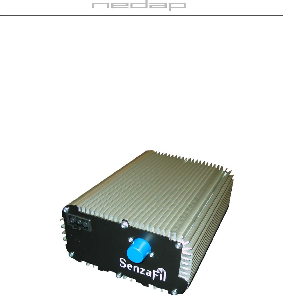
1. Brief product description
The Luxon Wireless 2450 can be added to the Luxon e-HID ballast or fixture. It regulates the communication between
the ballast/fixture and the Luxon Light Controller (LLC). After installation the Luxon Wireless 2450 becomes a RF node
in the network, and data can be send wirelessly to the light controller.
Luxon wireless 2450
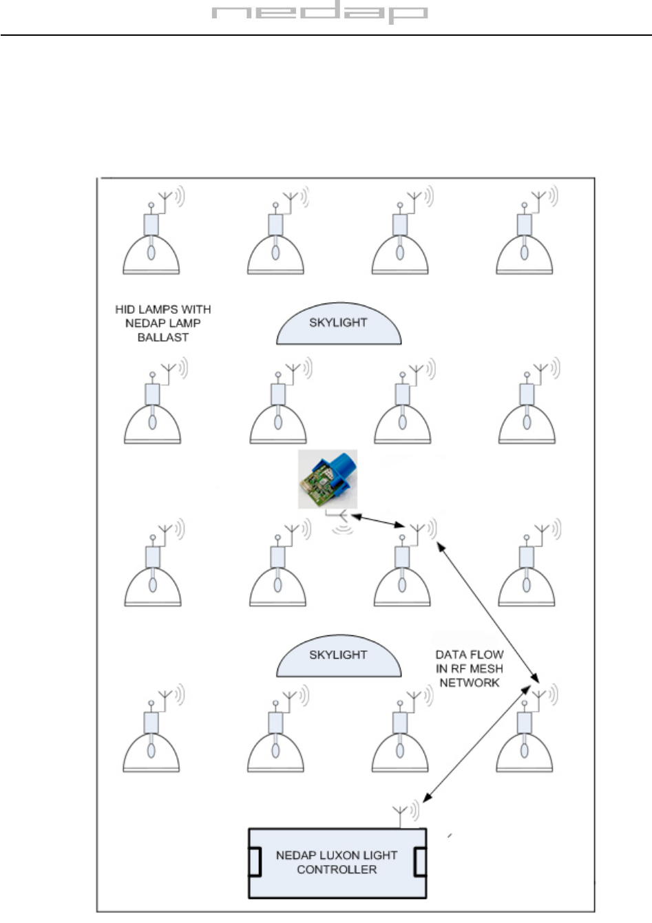
Figure 1. Installation example for the Luxon Wireless 2450 with HID lamps with a Mesh Network in a
building with skylights
Page 3 of 7
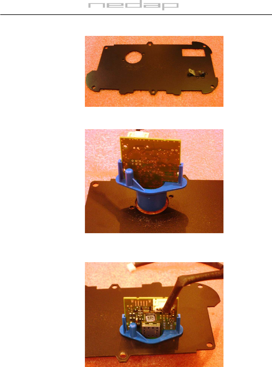
2. Assembly overview for the Luxon Wireless 2450
Figure 2a: Frontplate of the end use enclosure
Figure 2b: Luxon Wireless 2450 enclosure positioned on the spot mounted to the front plate
Figure 2c: Luxon Wireless 2450 enclosure positioned in the hole mounted to the front plate
Page 4 of 7
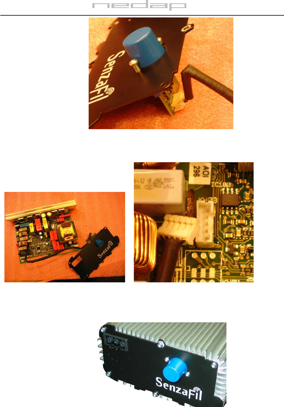
Figure 2d: Luxon Wireless 2450 mechanically secured to the front plate by screws
Figure 2e: Luxon Wireless 2450 wired to Figure 2f: Detailled photograph of the connectors
the Luxon e-HID ballast
Figure 2g: Frontview of the Luxon e-HID ballast
Page 5 of 7
3. Positioning
The Luxon Wireless 2450 will be mounted to a cover of a Luxon e-HID ballast or fixture
Note:
1) This transmitter should only be used or installed at locations where there is at least 20cm
separation distance between the antenna and all persons. This is to comply with FCC RF
exposure requirements for mobile transmitting devices.
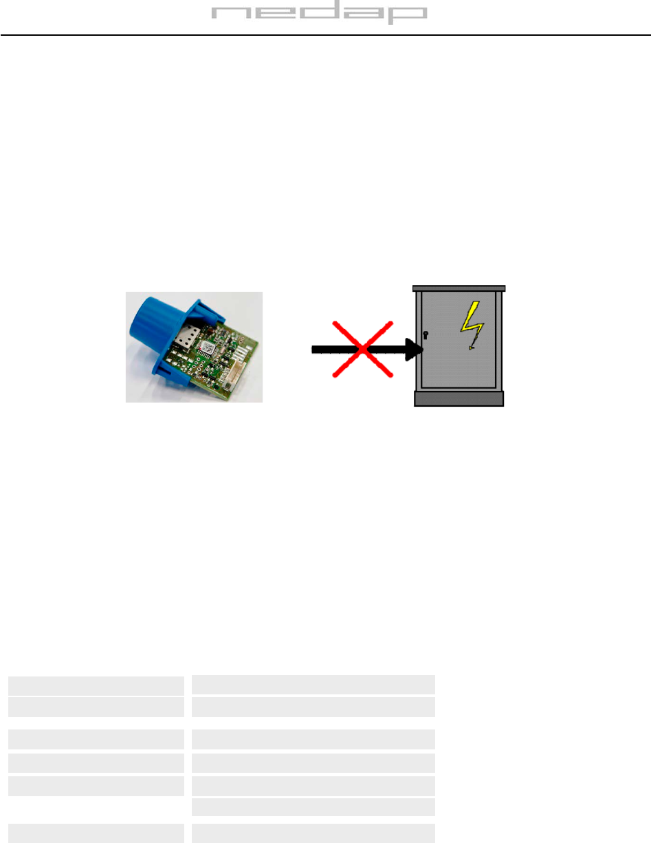
2) The Luxon Wireless 2450 shall never be installed inside a metal power cabinet. This would
impede wireless communication.
Fig 3 No installation of the Luxon Sensor Bridge inside a metal enclosure
5. Powering the Luxon Wireless 2450
The Luxon Wireless 2450 is powered by a 12V DC-source from the Luxon e-HID PCB.
6. Specifications for application Luxon Wireless 2450
Operating temperature
Safety
EMC/Telecom
-40 to +85°C
EN60950
EN301489-1, EN300328 V1.7.1
FCC47 part 15 and IC RSS210
Dimensions 40X53 mm
Input Supply 12 Vdc, max 0.1 mA
Page 6 of 7
7. FCC and IC Declarations for Luxon Wireless 2450
This device contains Luxon Wireless 2450 with
FCC ID: CGDLW2450 and IC: 1444A-LW2450
Compliance statement
This device complies with part 15 of the FCC Rules and to RSS210 of Industry Canada.
Operation is subject to the following two conditions:
(1) this device may not cause harmful interference, and
(2) this device must accept any interference received, including interference that may cause undesired operation.
Déclaration Conformité
Cet appareil se conforme aux normes RSS exemptés de license du Industry Canada.
L'opération est soumis aux deux conditions suivantes
(1) cet appareil ne doit causer aucune interférence, et
(2) cet appareil doit accepter n'importe quelle interférence, y inclus interférence qui peut causer une opération non pas
voulu de cet appareil.
Warning
Changes or modifications not expressly approved by the party responsible for compliance could void the user’s
authority to operate the equipment.
RF Exposure
To comply with FCC RF exposure requirements for mobile transmitting devices, this transmitter should only be used or
installed at locations where there is at least 20cm separation distance between the antenna and all persons.
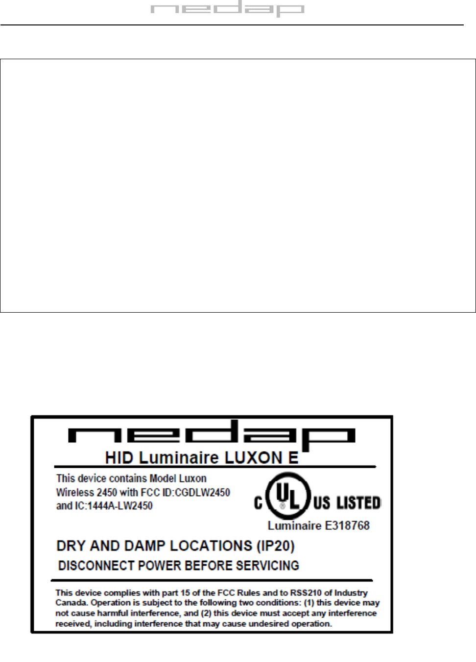
8. Label artwork for application Luxon Wireless 2450 end
product example
Fig 4: Label artwork for Luxon Wireless 2450 end product example.
Page 7 of 7
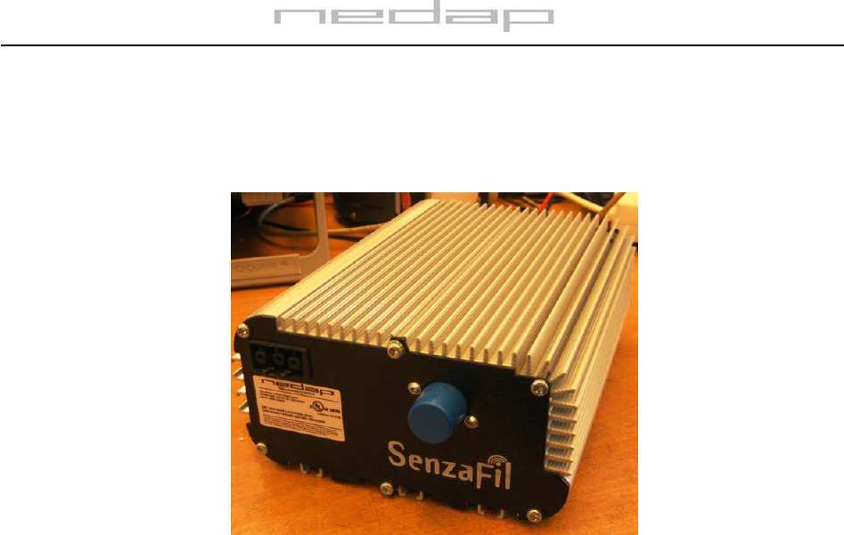
9. Label location Luxon e-HID ballast.
Attach the label to the Luxon e-HID ballast as shown in the following figure 5.
Fig. 5. Label location