Nedap N V SFSB Data Transmission System applied with a Sensor Bridge for lamps User Manual 01
N. V. Nederlandsche Apparatenfabriek NEDAP Data Transmission System applied with a Sensor Bridge for lamps 01
Contents
- 1. User manual 01
- 2. User manual 02
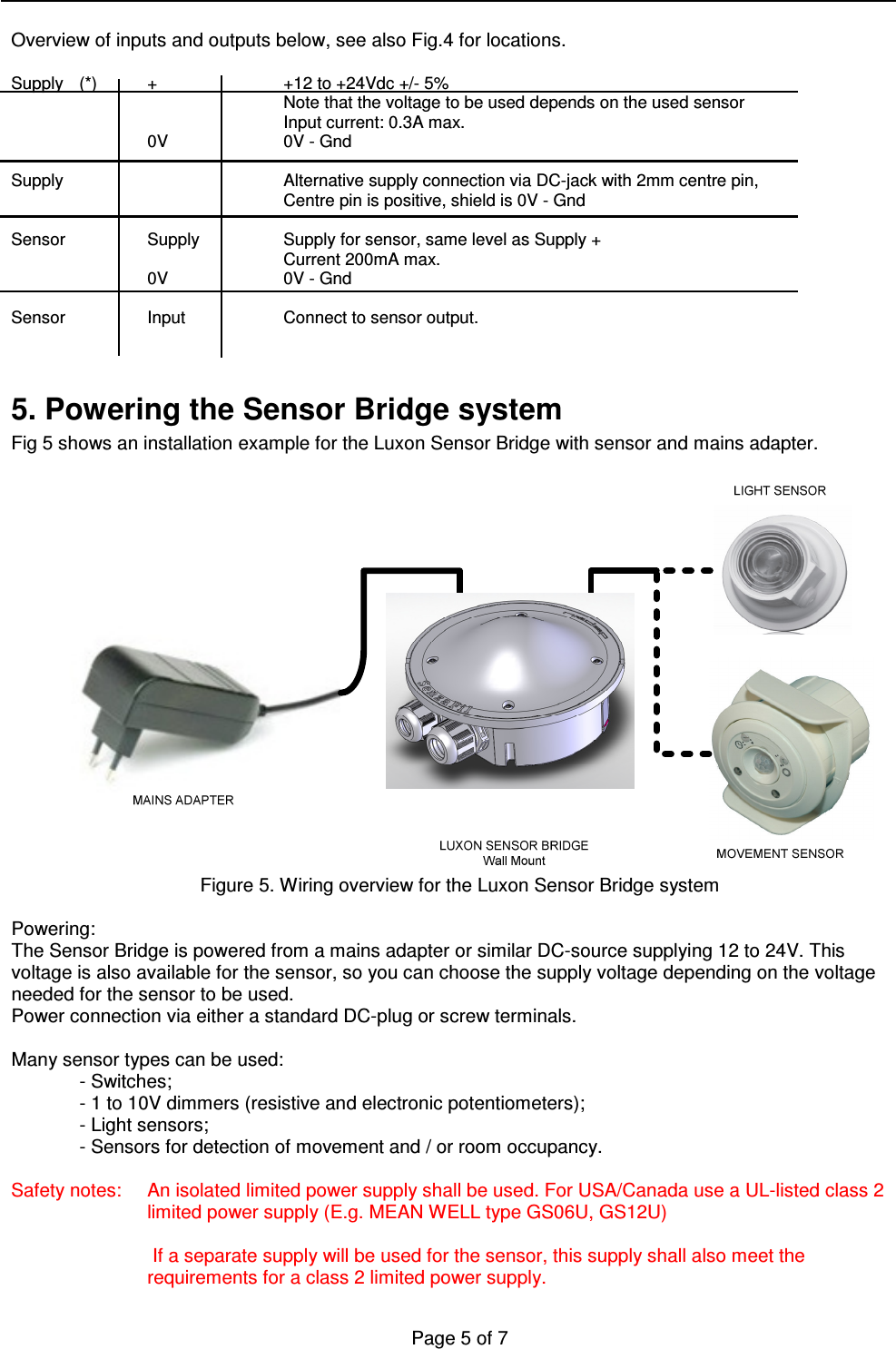
User manual 01