Nedap N V TDC Deactivator User Manual TDC V1 20
N. V. Nederlandsche Apparatenfabriek NEDAP Deactivator TDC V1 20
UserManual.wiki
>
Nedap N V
>
TDC User Manual
>
user manual
Contents
1.
user manual
2.
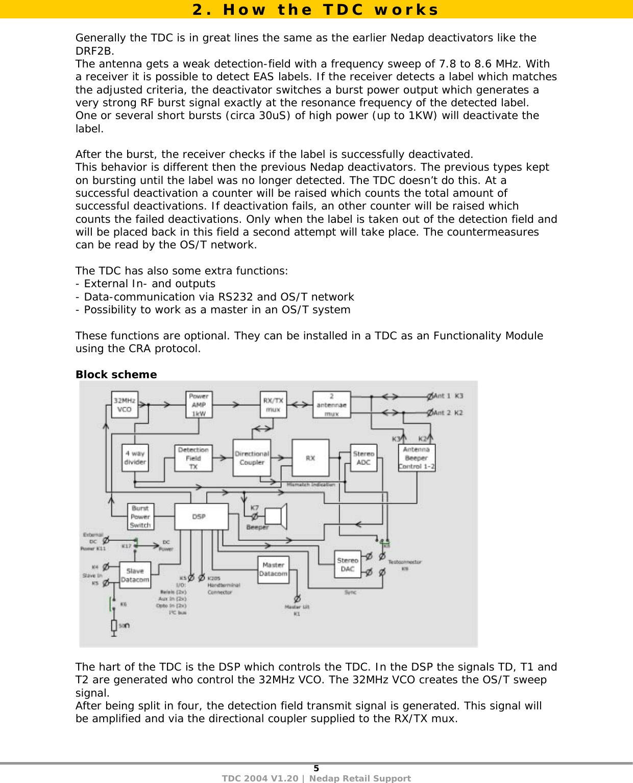
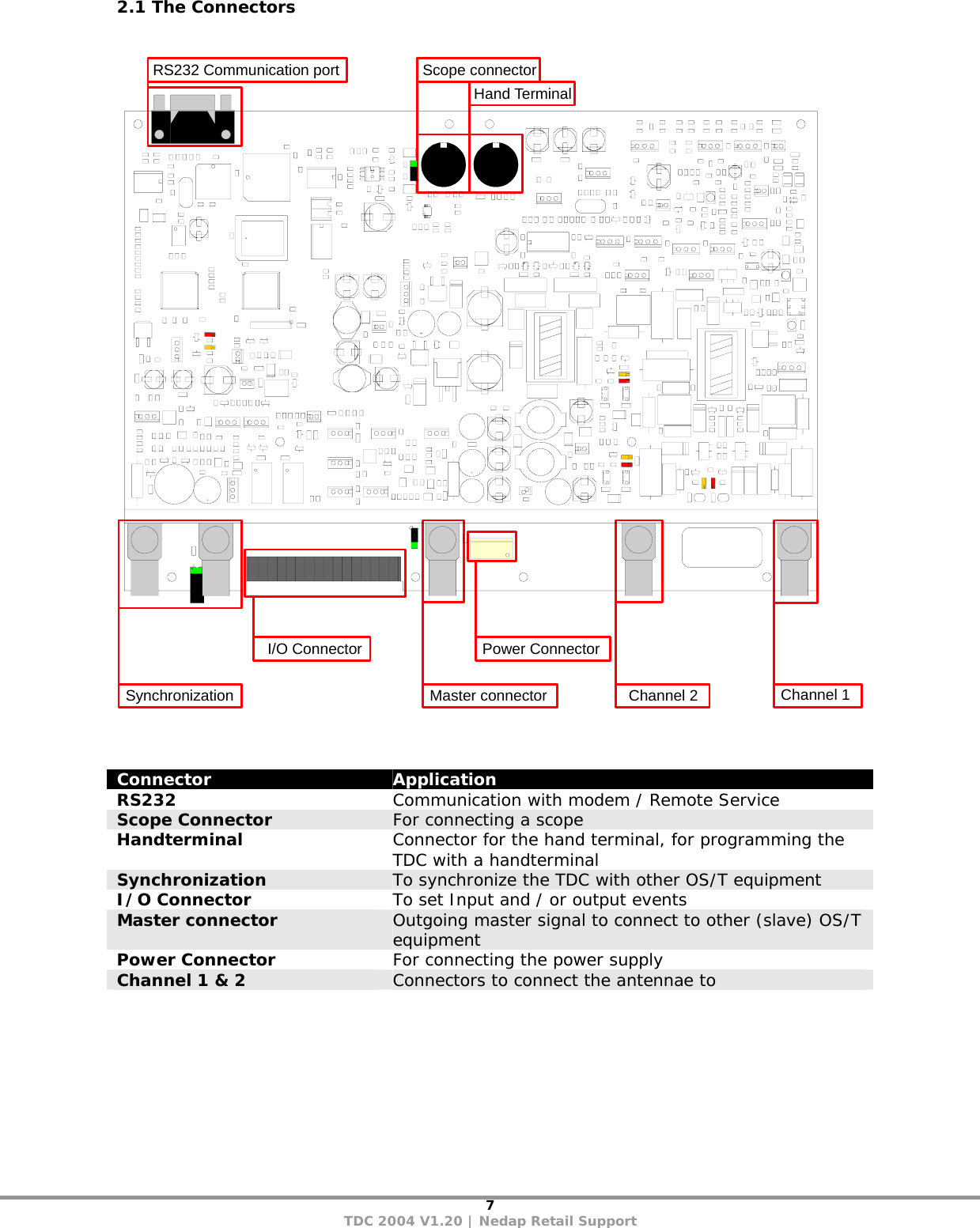
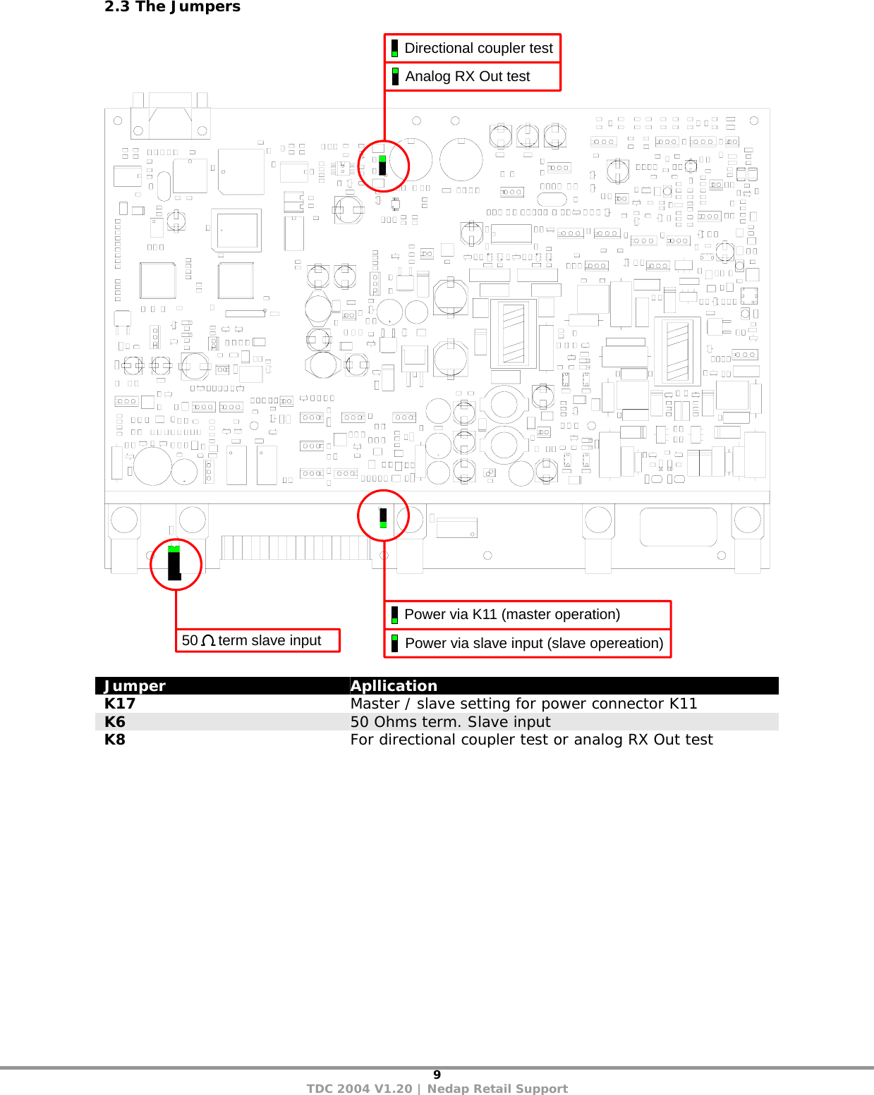
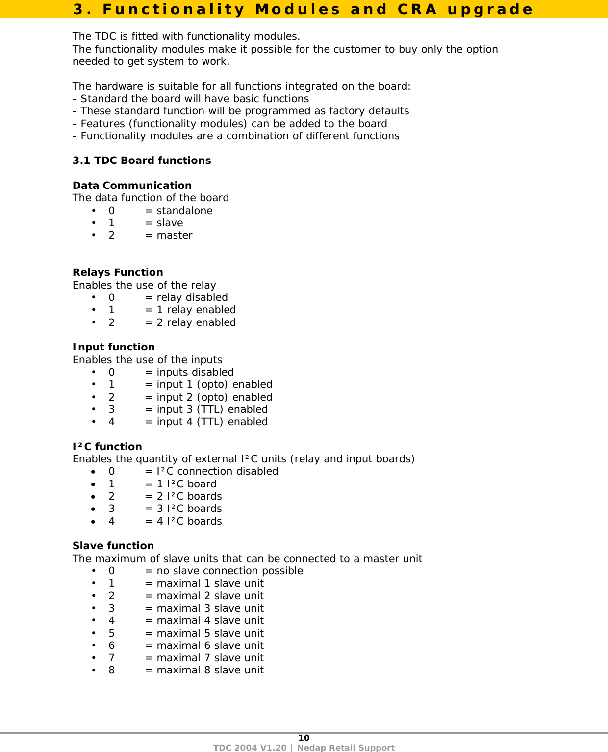
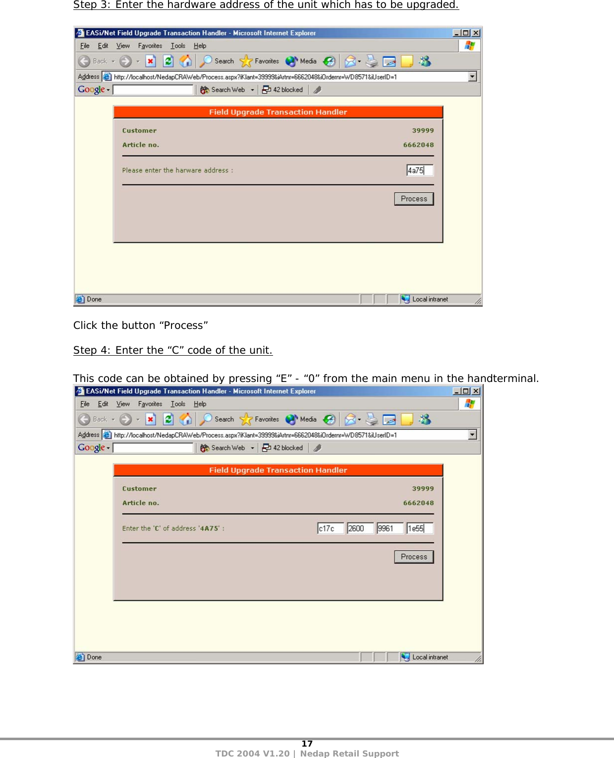
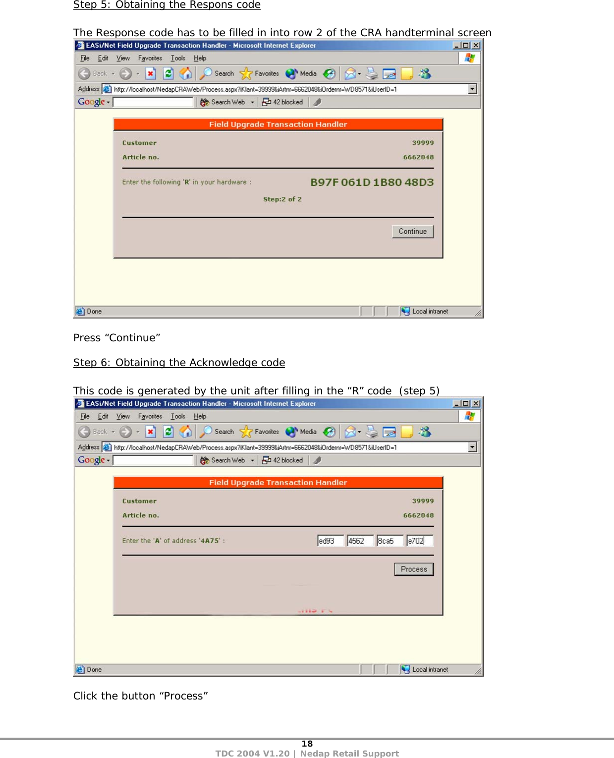
User Manual 1
3.
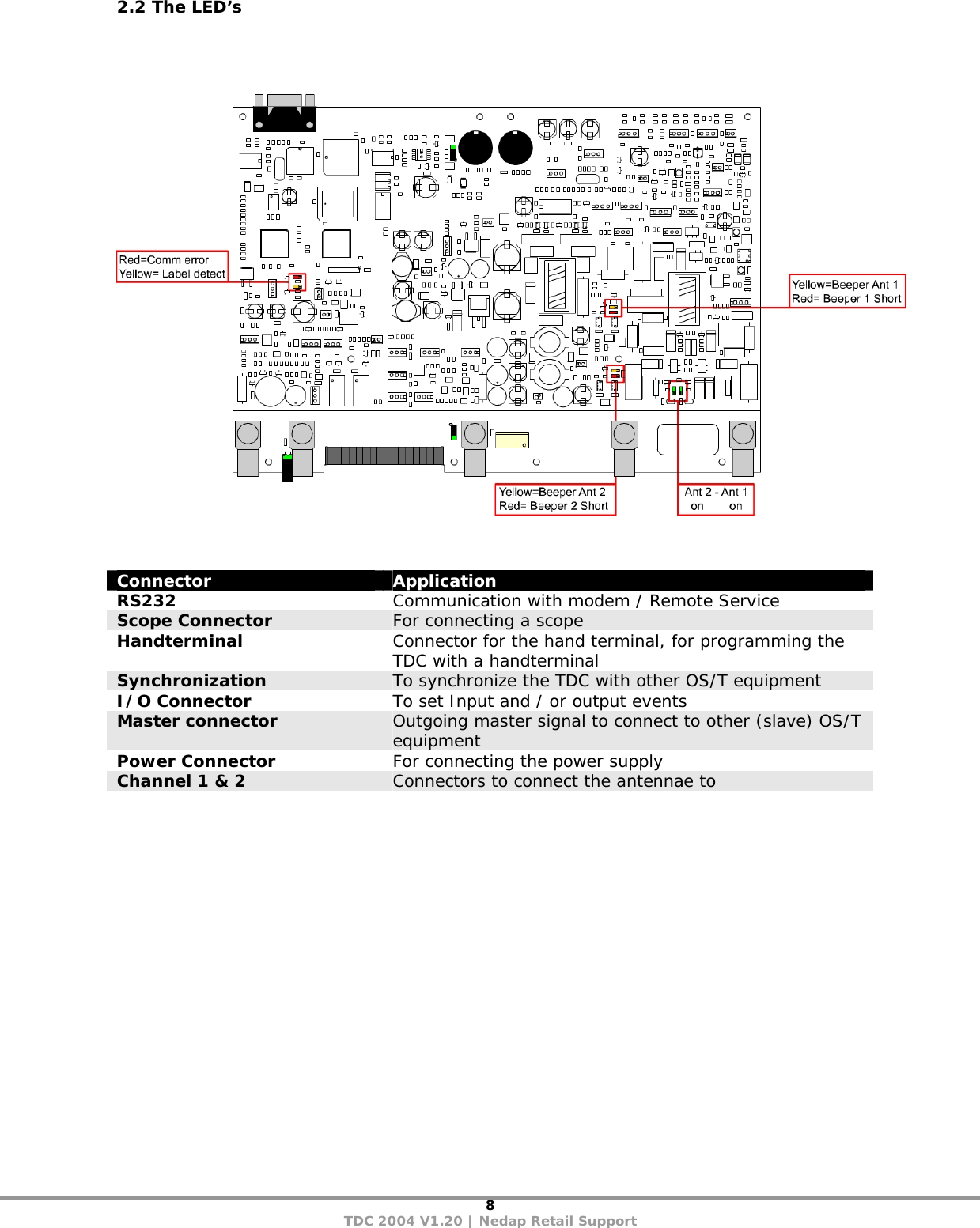
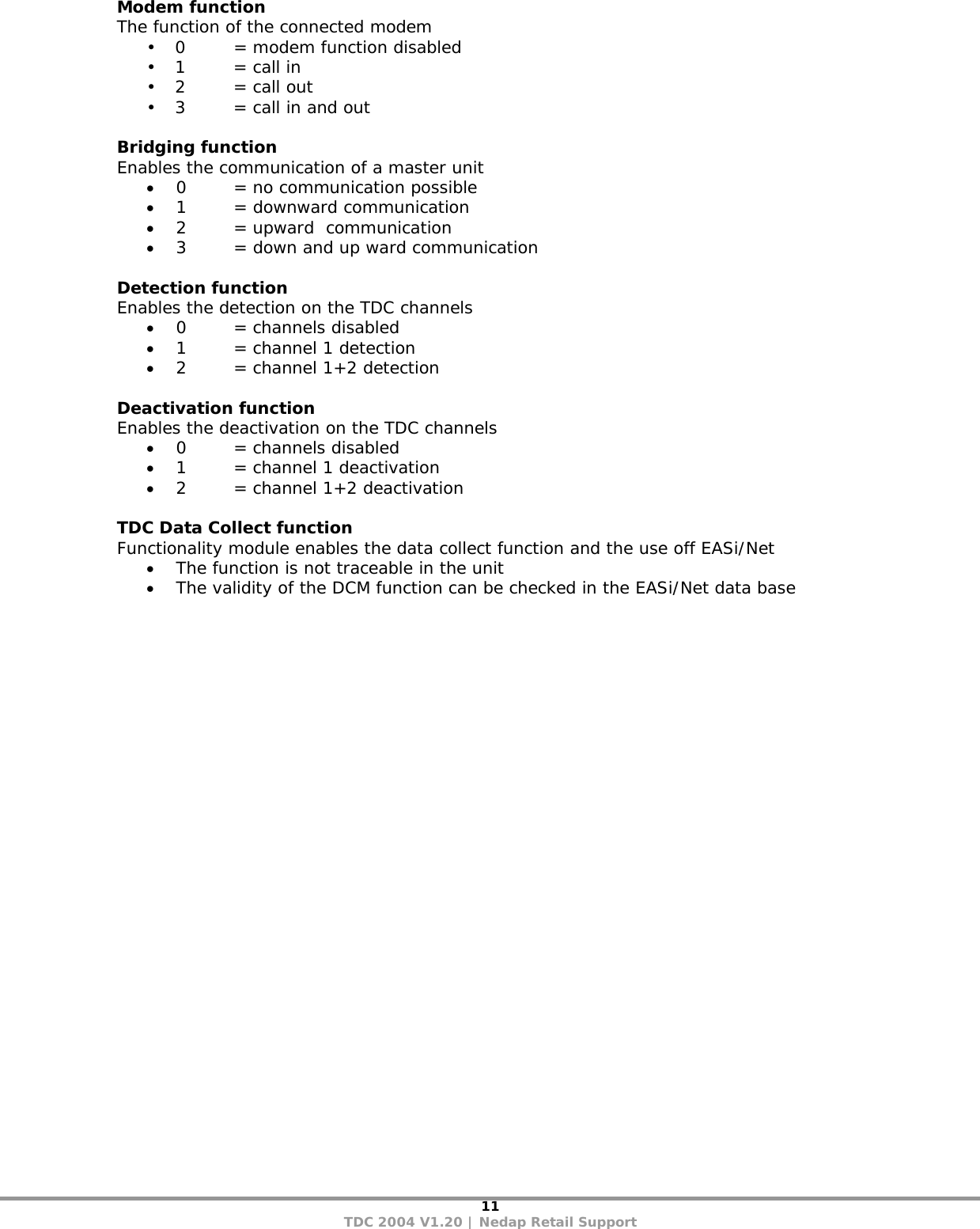
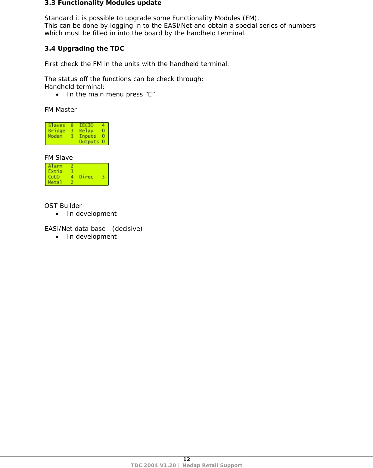
User Manual 2
user manual
Navigation menu
Upload a User Manual
Namespaces
Wiki Guide
HTML
PDF
Info
Views
User Manual
Discussion / Help
Navigation