Nedap N V TRANSIT 2.4 GHz Microwave ID System User Manual MEMO
N. V. Nederlandsche Apparatenfabriek NEDAP 2.4 GHz Microwave ID System MEMO
UserManual.wiki
>
Nedap N V
>
TRANSIT User Manual
User manual
Navigation menu
Upload a User Manual
Namespaces
Wiki Guide
HTML
PDF
Info
Views
User Manual
Discussion / Help
Navigation

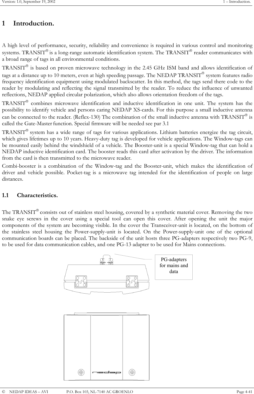
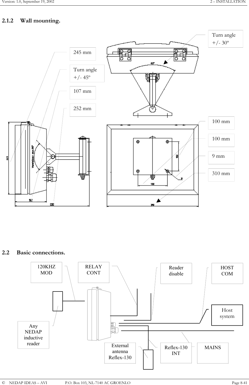
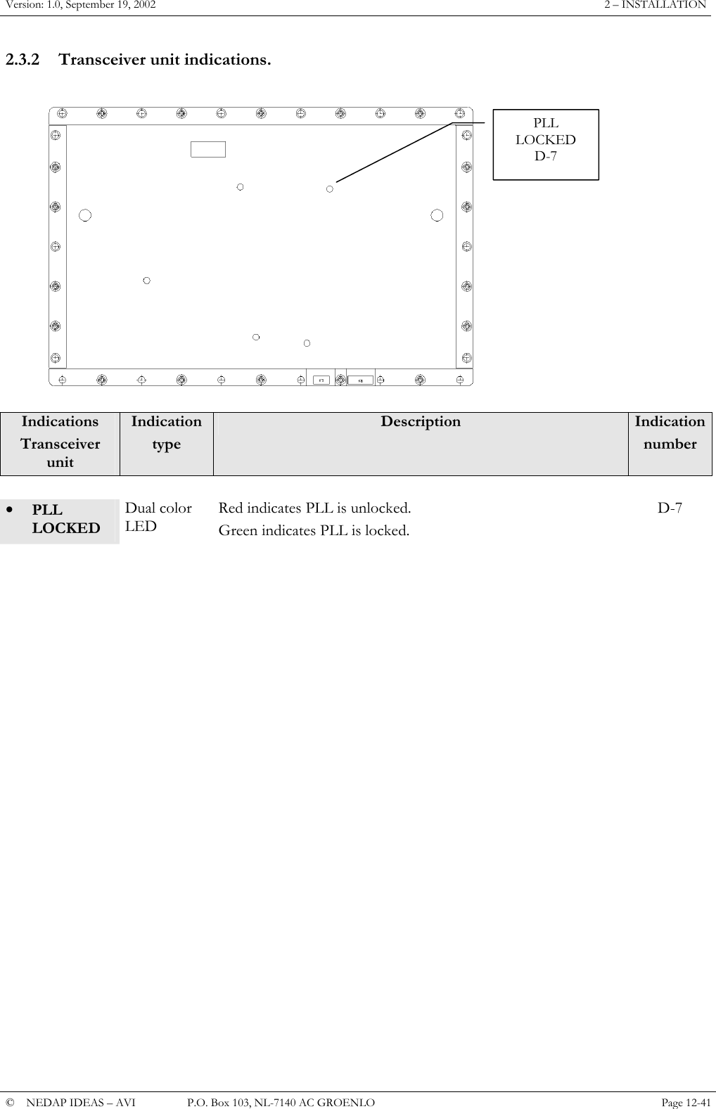
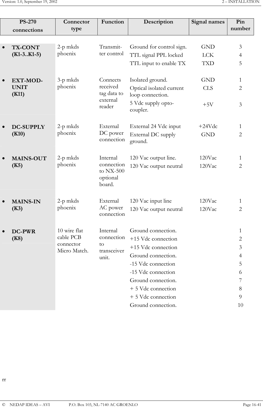
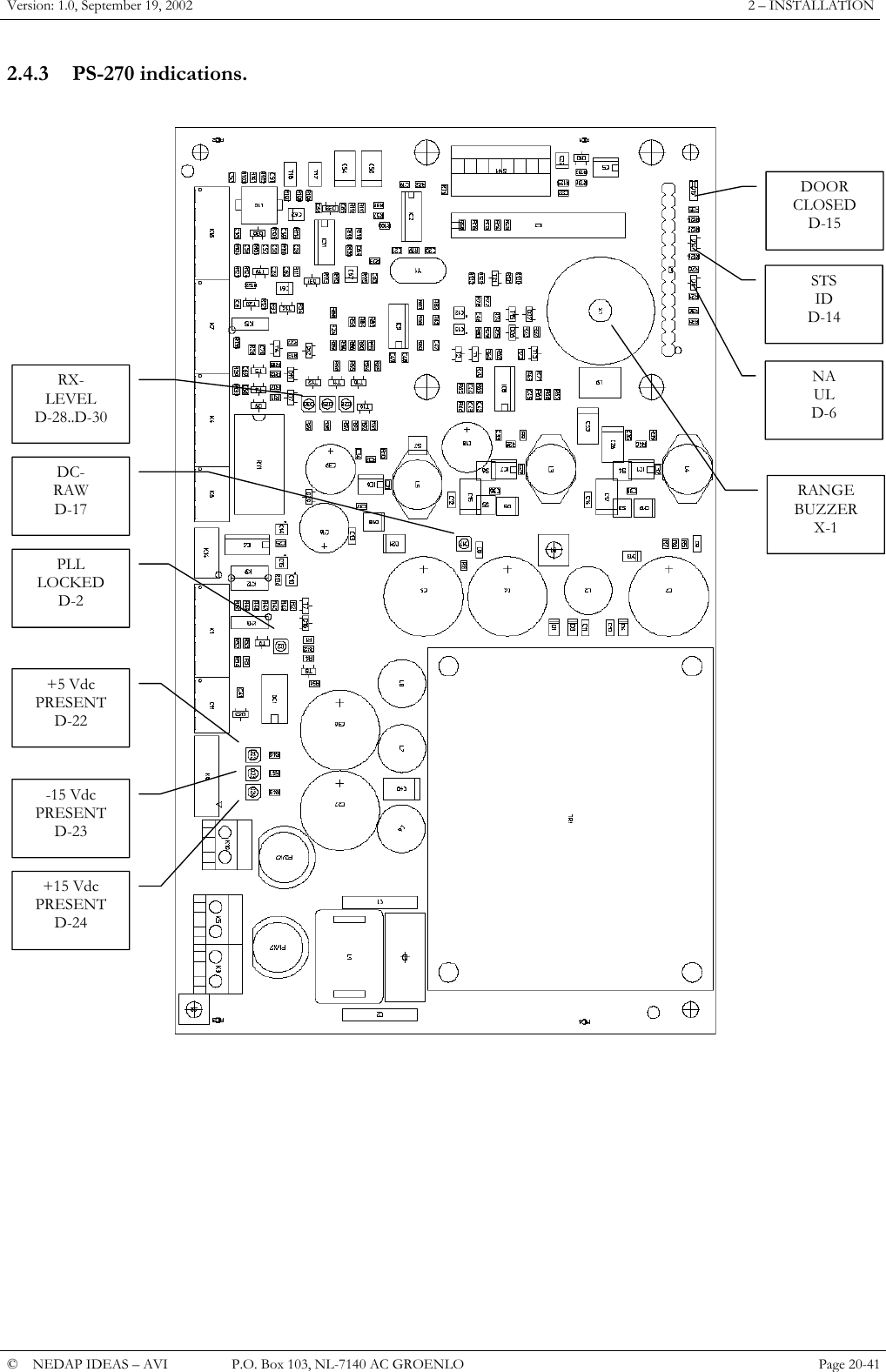
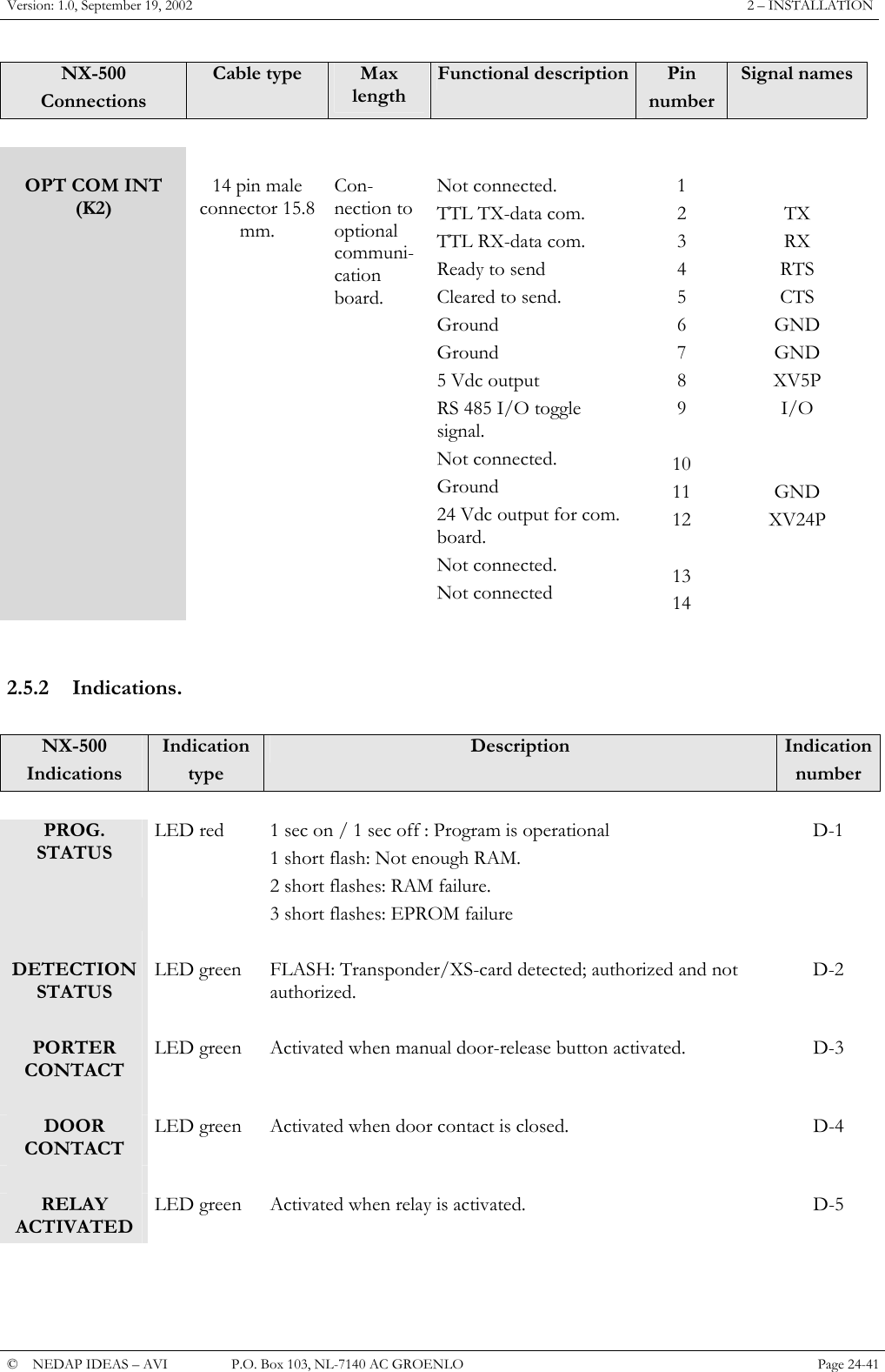
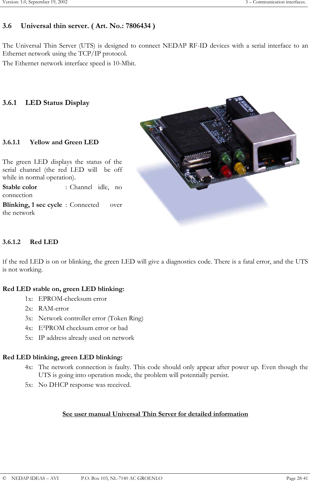
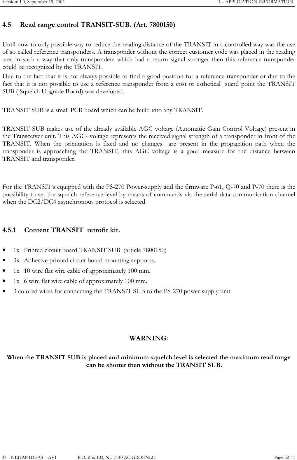
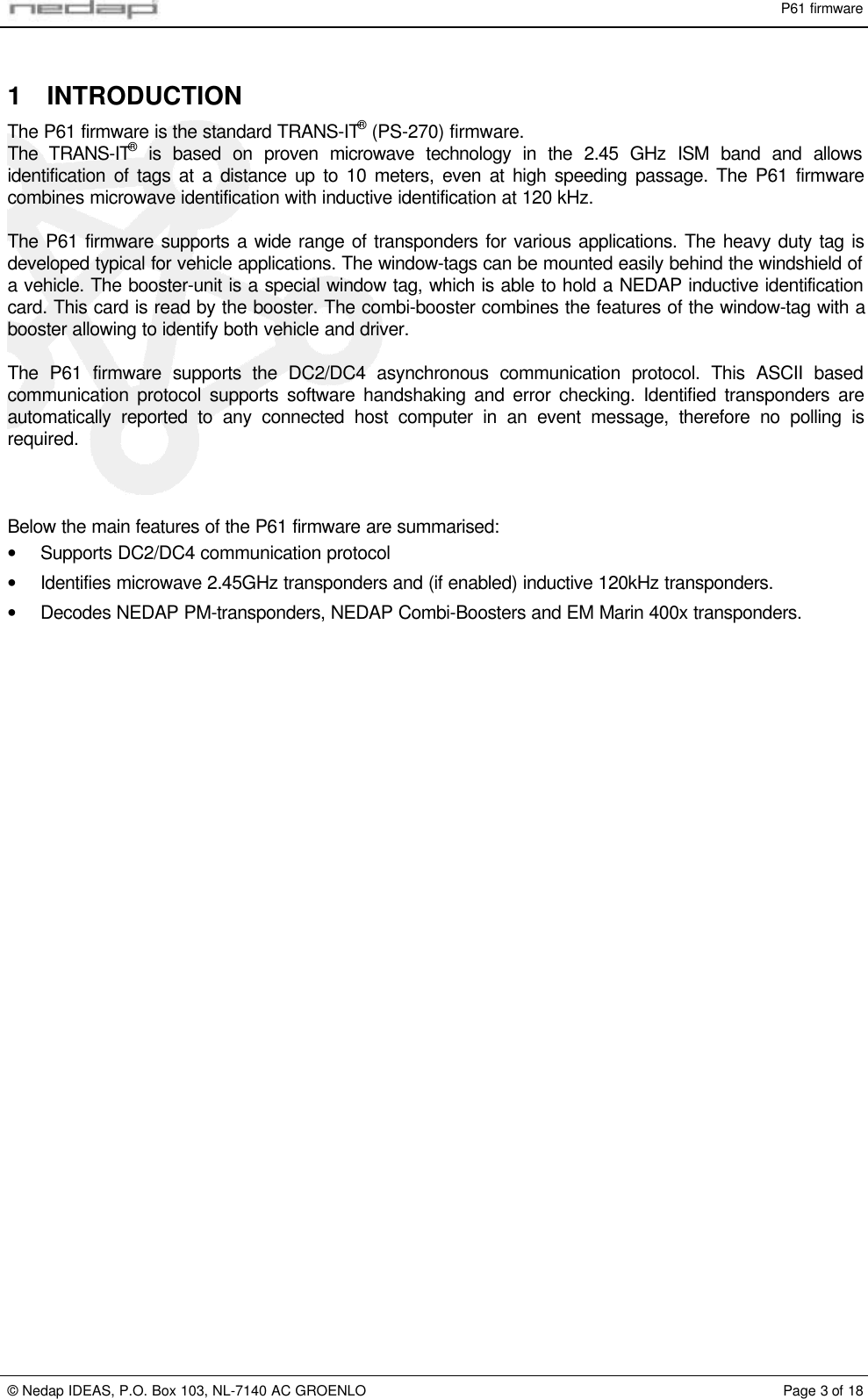
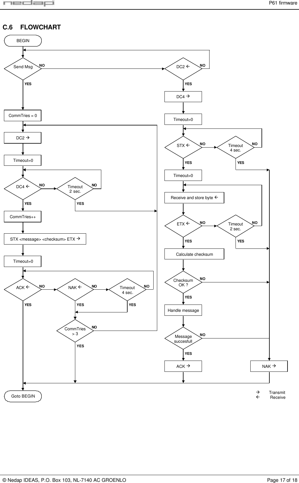
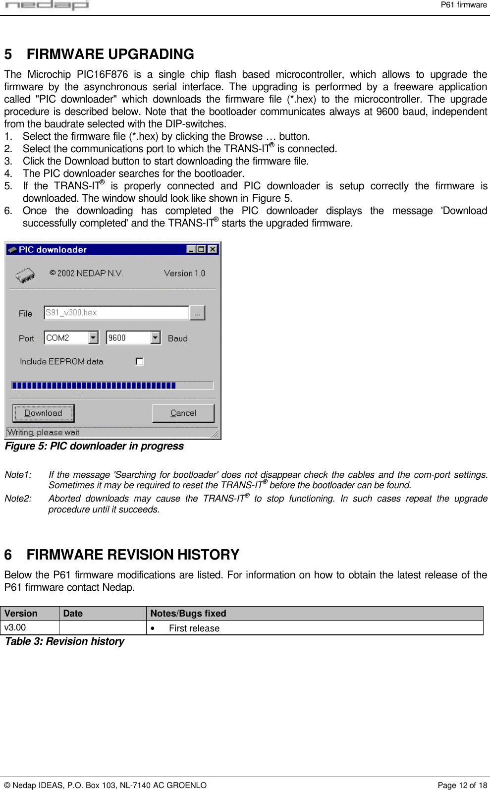
![P61 firmware© Nedap IDEAS, P.O. Box 103, NL-7140 AC GROENLO Page 5 of 184 APPLICATION INFORMATIONThe main function of the reader is to detect NEDAP transponders and to transmit its identification numberto a host computer. The id-number will be sent to the host in a so-called event message. A detaileddescription of each event message is given in chapter 4.1.1.Command messages allow a host computer to change settings in the reader or to request information fromthe reader. The command messages are described in chapter 4.1.2.4.1 DC2/DC4 PROTOCOLDC2/DC4 protocol is the standard Nedap protocol which supports two-way communications, error checkingand software handshaking.This chapter describes the application layer of the DC2/DC4 protocol as it is implemented in the P61firmware. Refer to appendix C for a description of the DC2/DC4 protocol details.4.1.1 EVENT MESSAGESEvent messages are messages that report to the host computer that a specific event has occurred insidethe reader. There are different types of event messages that may be send by the reader, like the detectionevent that is sent when a transponder is identified.Event messages, when they occur, are stored locally in the reader in the event buffer. Oncecommunication is idle the reader will try to transmit the event message. A maximum of 3 event messagescan be stored. When the event buffer is full a new event will overwrite the oldest one. The event buffer islocated in RAM memory and its contents will be lost when the power is off.The reader may send the following event messages. Protocol dependant characters are not shown here.Spaces are added for clarity.Spaces are only added for readability.O-event: Reader restartedDescription: The reader sends this event message as soon as the reader is powered-up toindicate that the system is active. Application settings stored in EEPROM werenot lost.Syntax: 01 01 01 20 O [????????]Where: [????????]Optional unused timestamp. Can be enabled with commandmessage 0265.Notes: In case the P-event is sent the O-event is omitted.P-event: Reader resetDescription: The reader sends this event message as soon as the reader is powered-up toindicate that the system is active. Application settings stored in EEPROM werereset to their factory default. EEPROM settings are not lost when the reader isswitched off. The EEPROM settings may be lost when the firmware is changed.Syntax: 01 01 01 20 P [????????]Where: [????????]Optional unused timestamp. Can be enabled with commandmessage 0265.Notes: In case the P-event is sent the O-event is omitted.](https://usermanual.wiki/Nedap-N-V/TRANSIT/User-Guide-279257-Page-46.png)
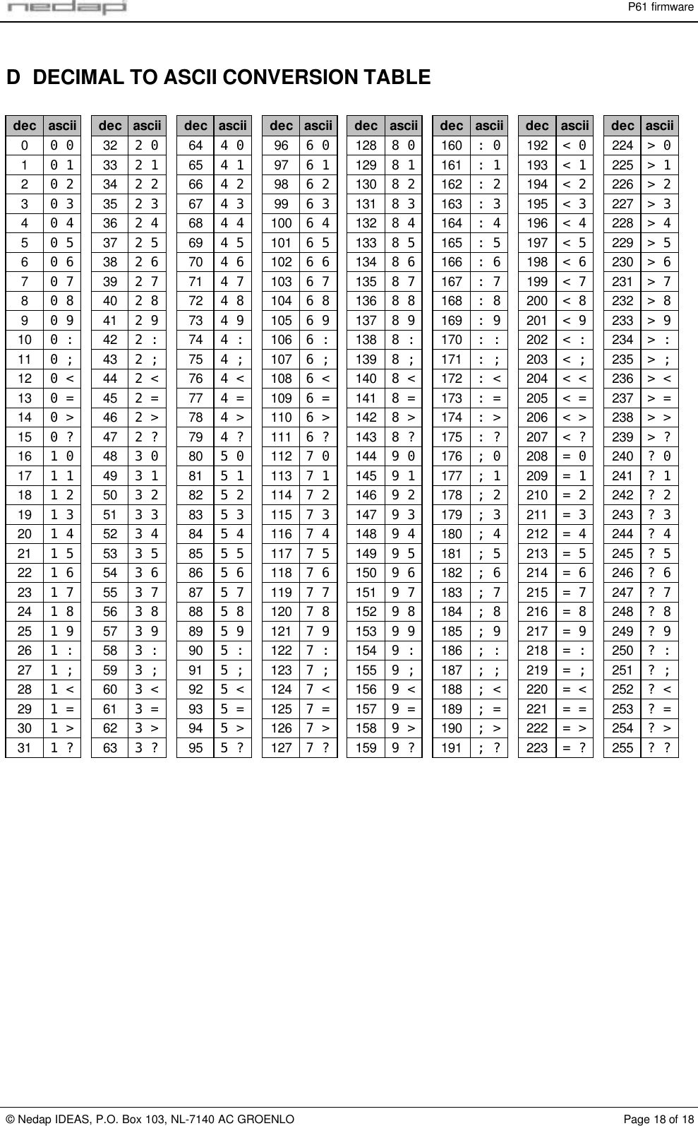
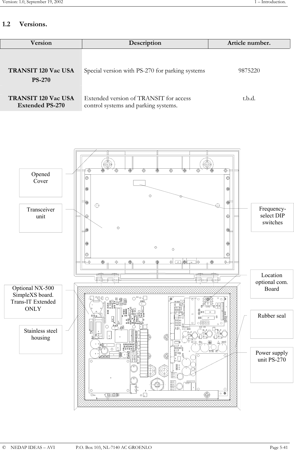
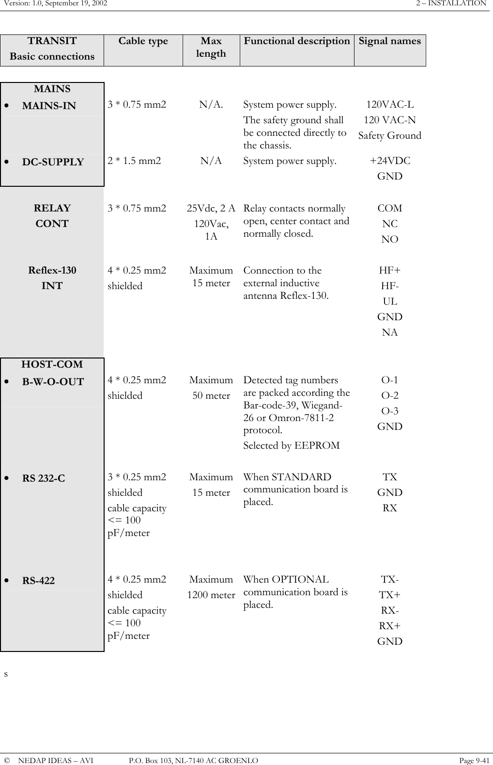
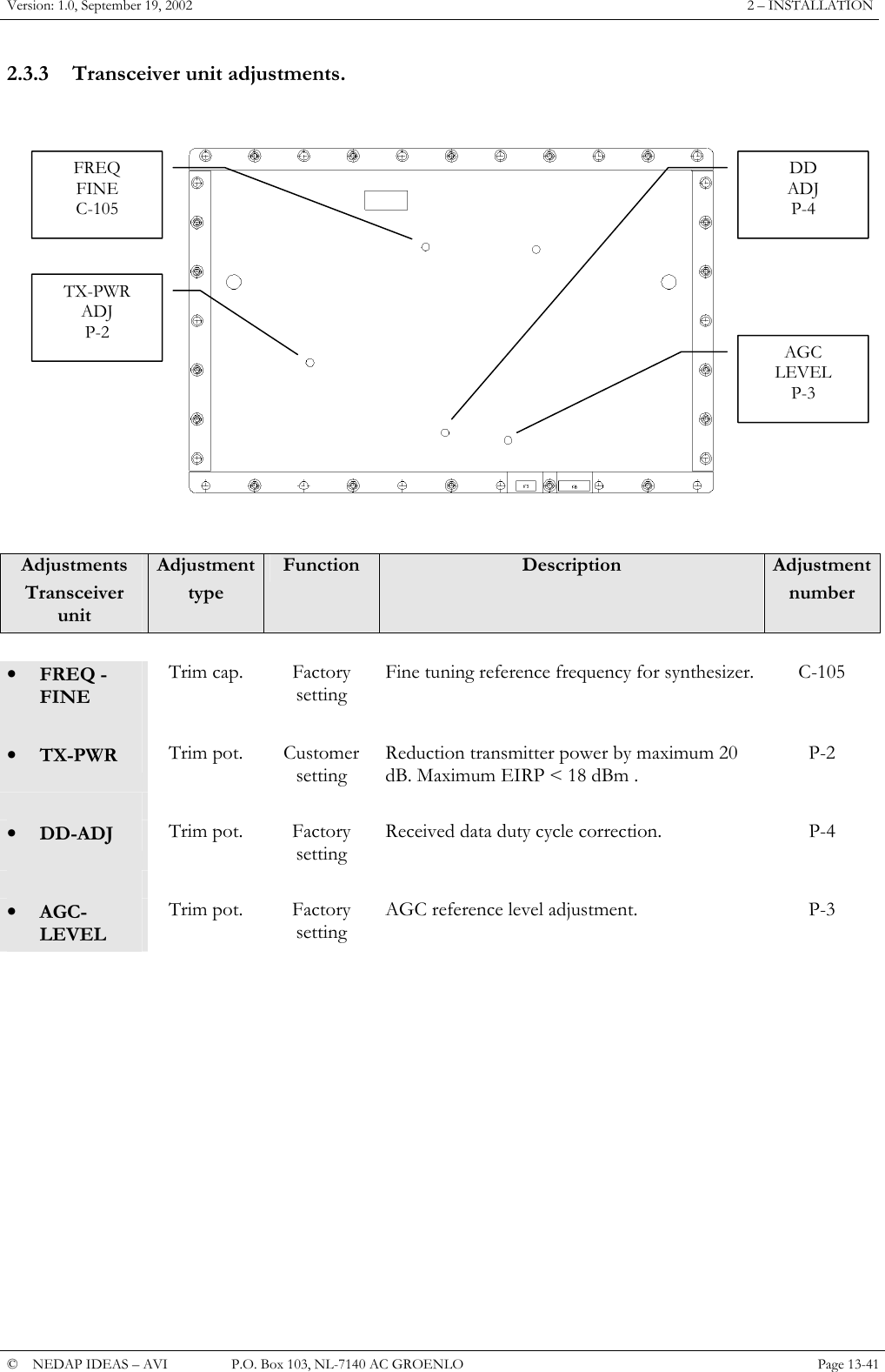
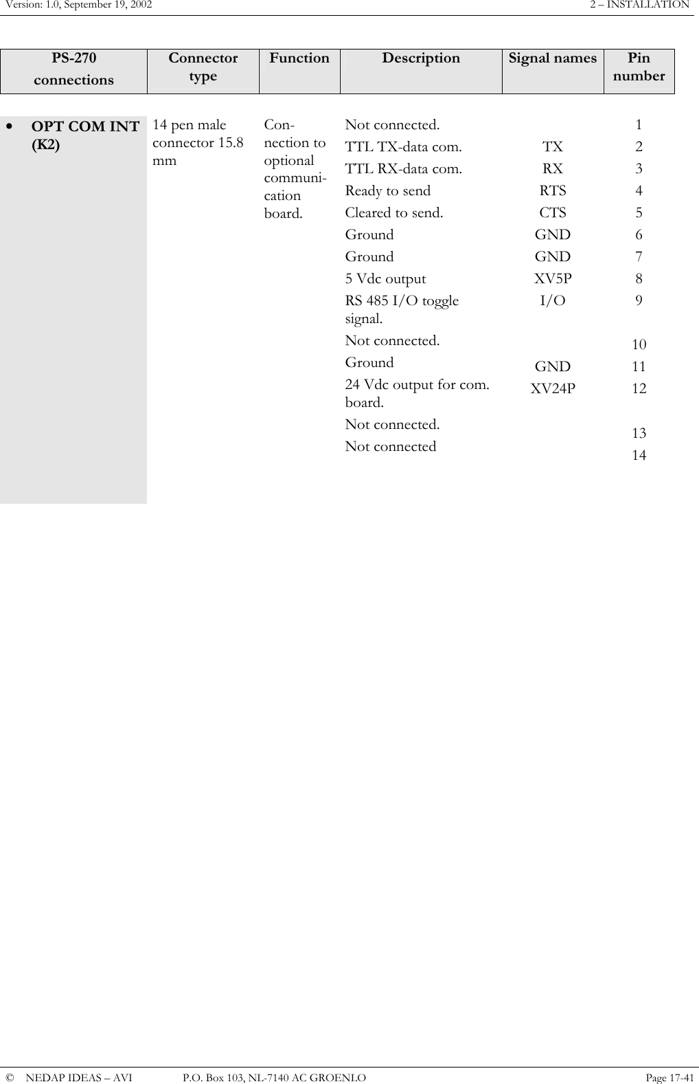
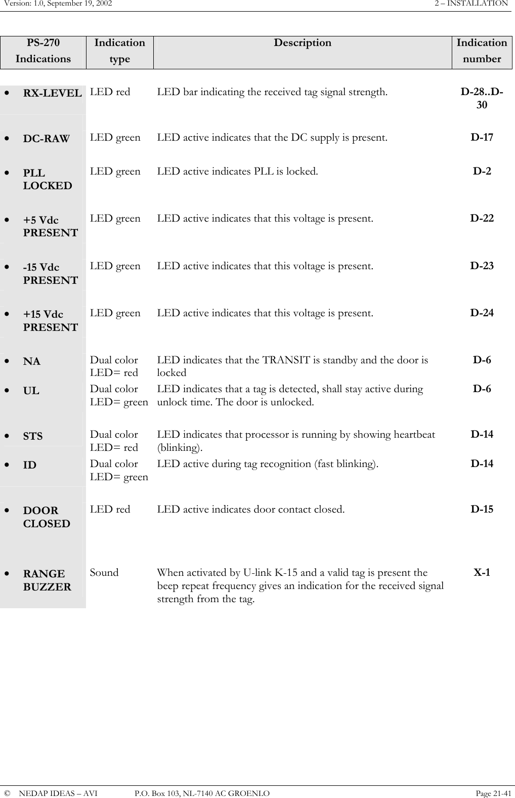
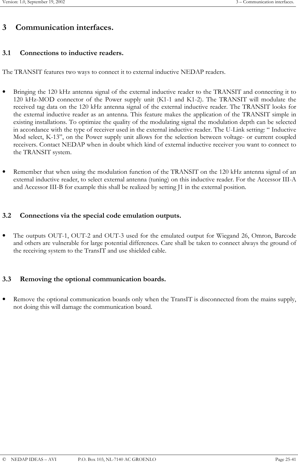
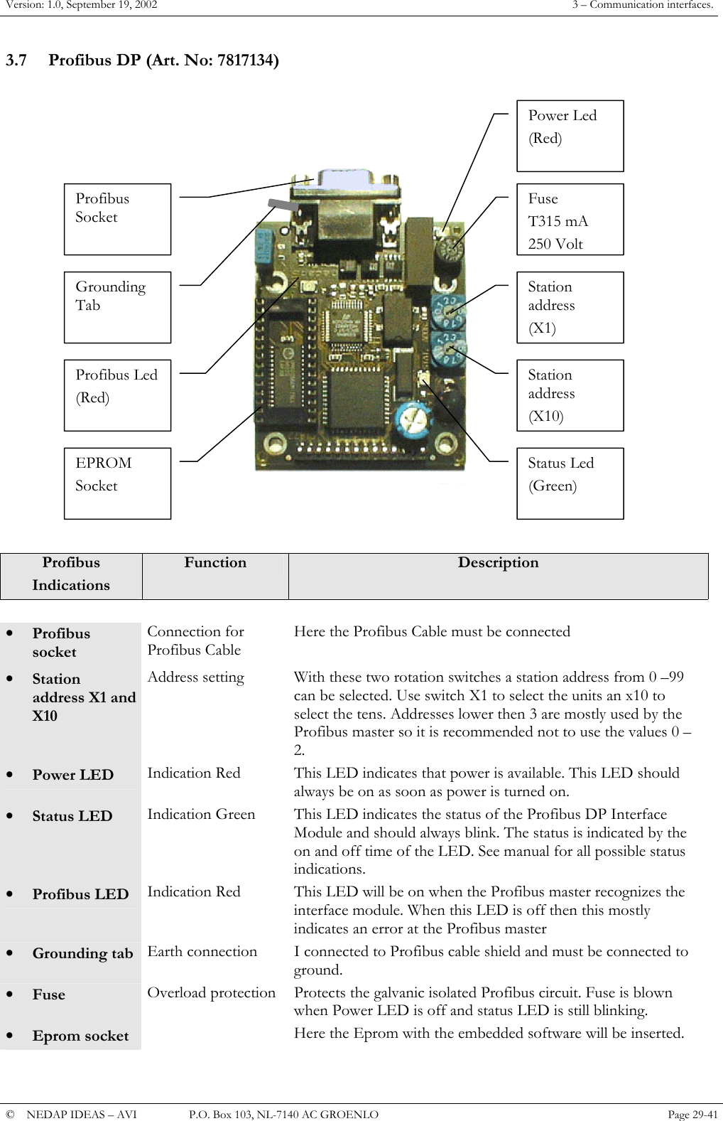
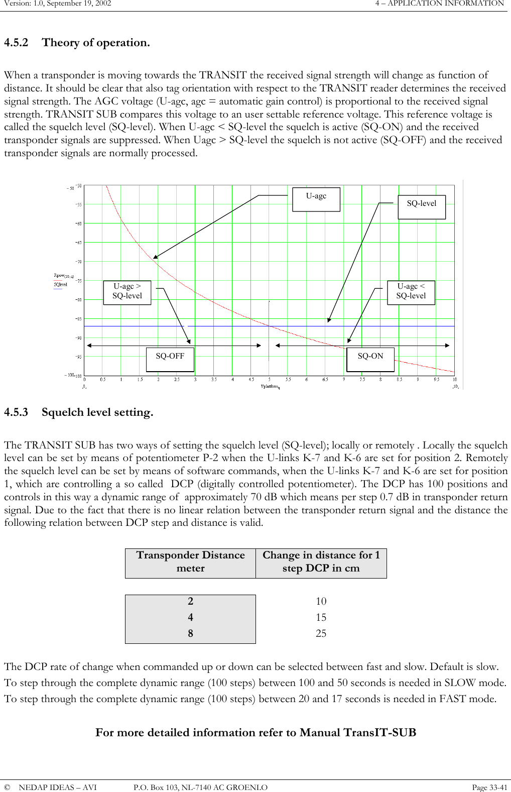
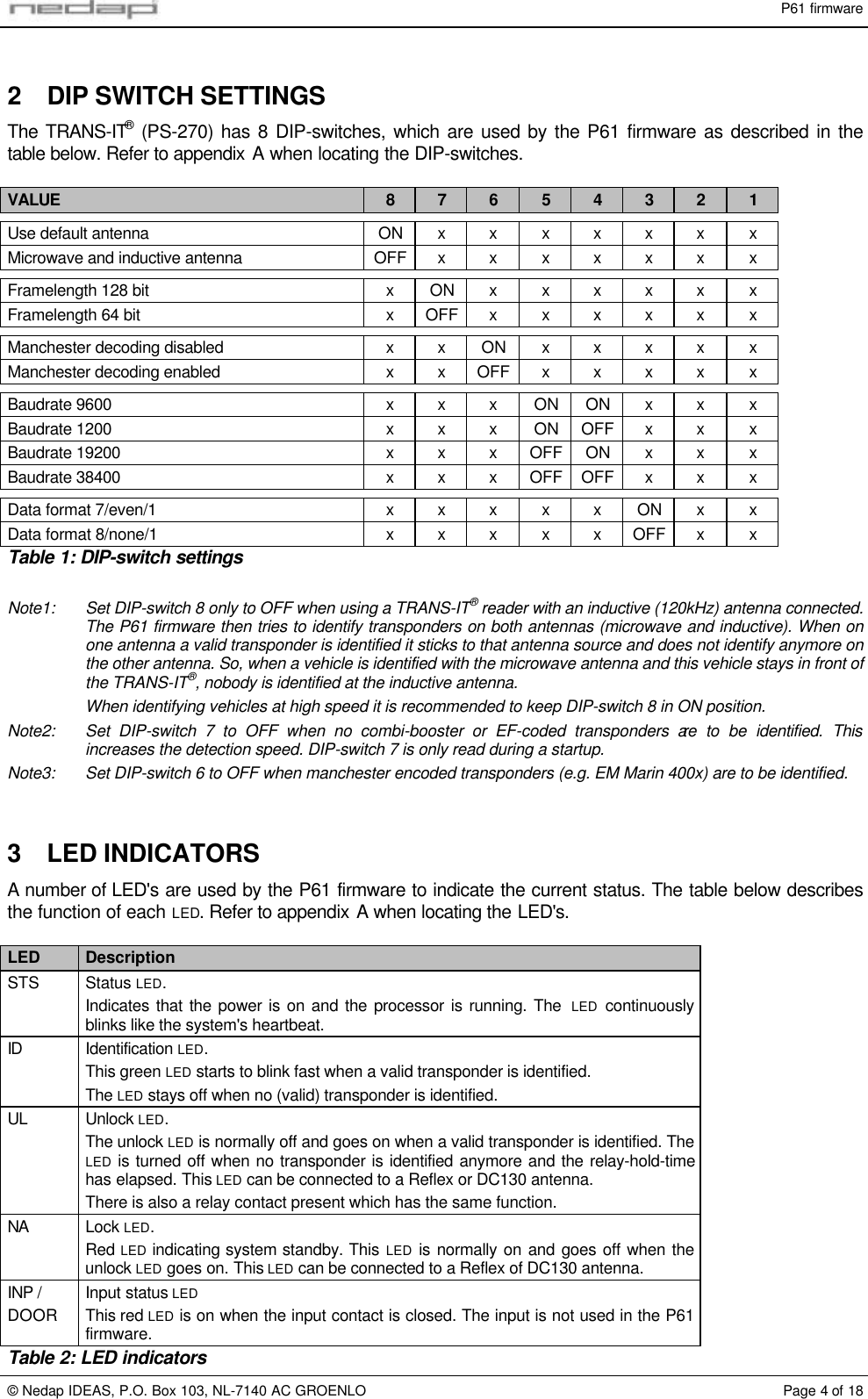
![P61 firmware© Nedap IDEAS, P.O. Box 103, NL-7140 AC GROENLO Page 6 of 18N-event: Transponder identified (6-digit CF/DF/GF-code)Description: When a transponder is identified this event message reports its identificationnumber. This event is only sent when a 6-digit transponder is identified. See alsothe timing diagram in Figure 1.Syntax: 01 01 01 20 N [????????] nnnnnnWhere: [????????]Optional unused timestamp. Can be enabled with commandmessage 0265.nnnnnn Identification number in range from 1 to 999999.DetectionEvent messageFigure 1: Timing diagram detection eventN-event: End of detection (6-digit CF/DF/GF-code)Description: This event message is transmitted when a previously identified transponder is nolonger present. The event is not send until the holdtime has expired.Syntax: 01 01 01 20 N [????????] 000000Where: [????????]Optional unused timestamp. Can be enabled with commandmessage 0265.Notes: Not every detection event has to be followed by a end-of-detection event. See thetiming diagram in Figure 2.DetectionHoldtimeEvent messageID-1 ID-2ID-1 ID-2 End-of-detectionFigure 2: Timing diagram end-of-detection eventU-event: Combi-booster identifiedDescription: When a combi-booster is identified this event message reports both identificationnumbers. The first identification number is from the combi-booster, the secondnumber is from the card which may be placed in the combi-booster.Syntax: 01 01 01 20 U [????????] 0000aaaaaa bbbbbbbbbbWhere: [????????]Optional unused timestamp. Can be enabled with commandmessage 0265.aaaaaa Combi-booster identification number in range from 1 to 999999.bbbbbbbbbb Card identification number. Can be hexadecimal if a EM-Marin 400xtransponder card is used.Notes: When no card is placed in the combi-booster the second identification number isleft blank (filled with zeros).U-event: Transponder identified (80-bit EF-code)Description: When a transponder is identified this event message reports its identificationnumber. This event is only sent when an 80-bit transponder is identified.Syntax: 01 01 01 20 U [????????] xxxxxxxxxxxxxxxxxxxxWhere: [????????]Optional unused timestamp. Can be enabled with commandmessage 0265.xxx...xxx Identification number 80 bit hexadecimal.xHexadecimal character made out of 4 bits (nibble) added with thevalue of character '0'.](https://usermanual.wiki/Nedap-N-V/TRANSIT/User-Guide-279257-Page-47.png)
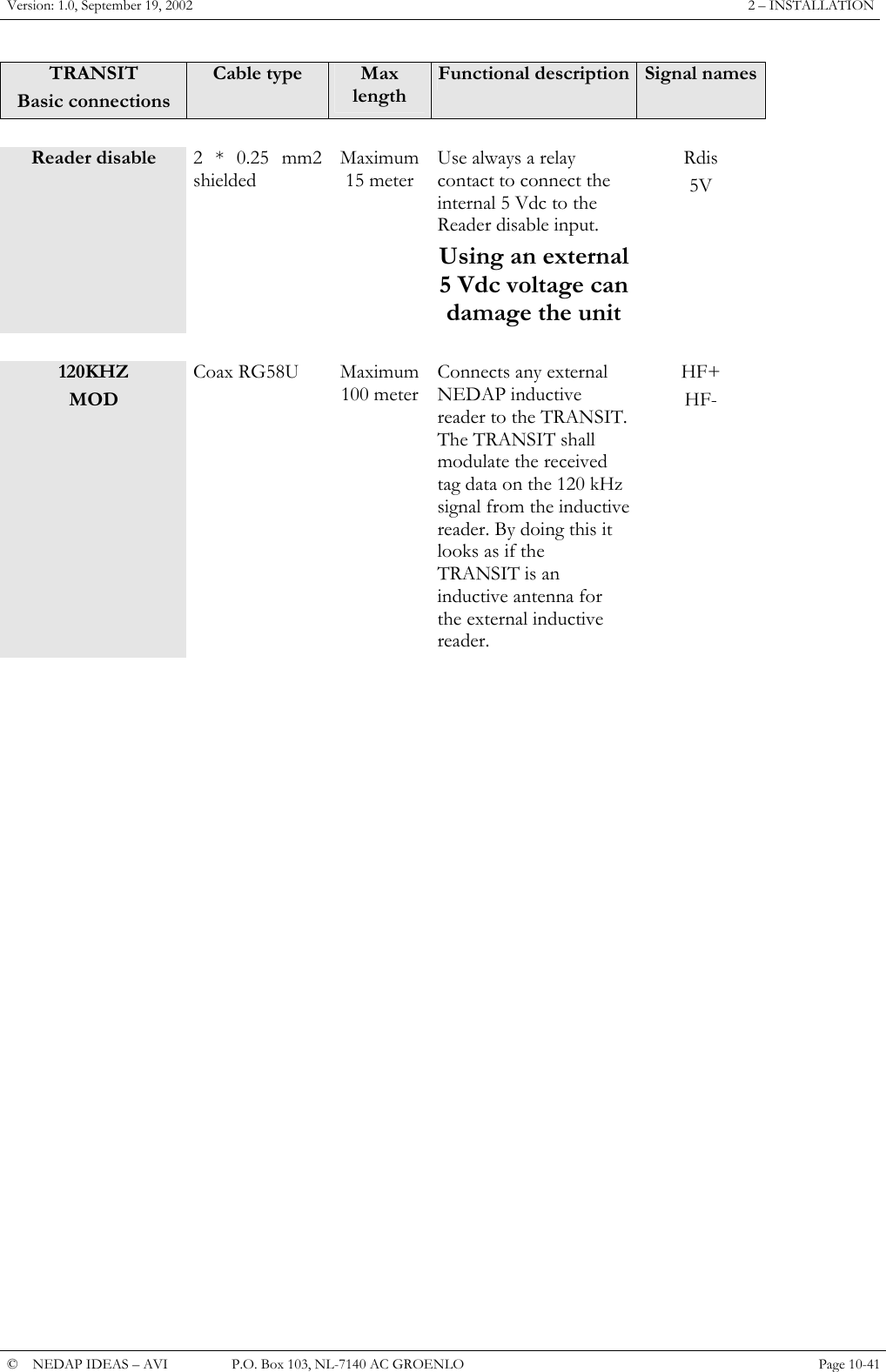
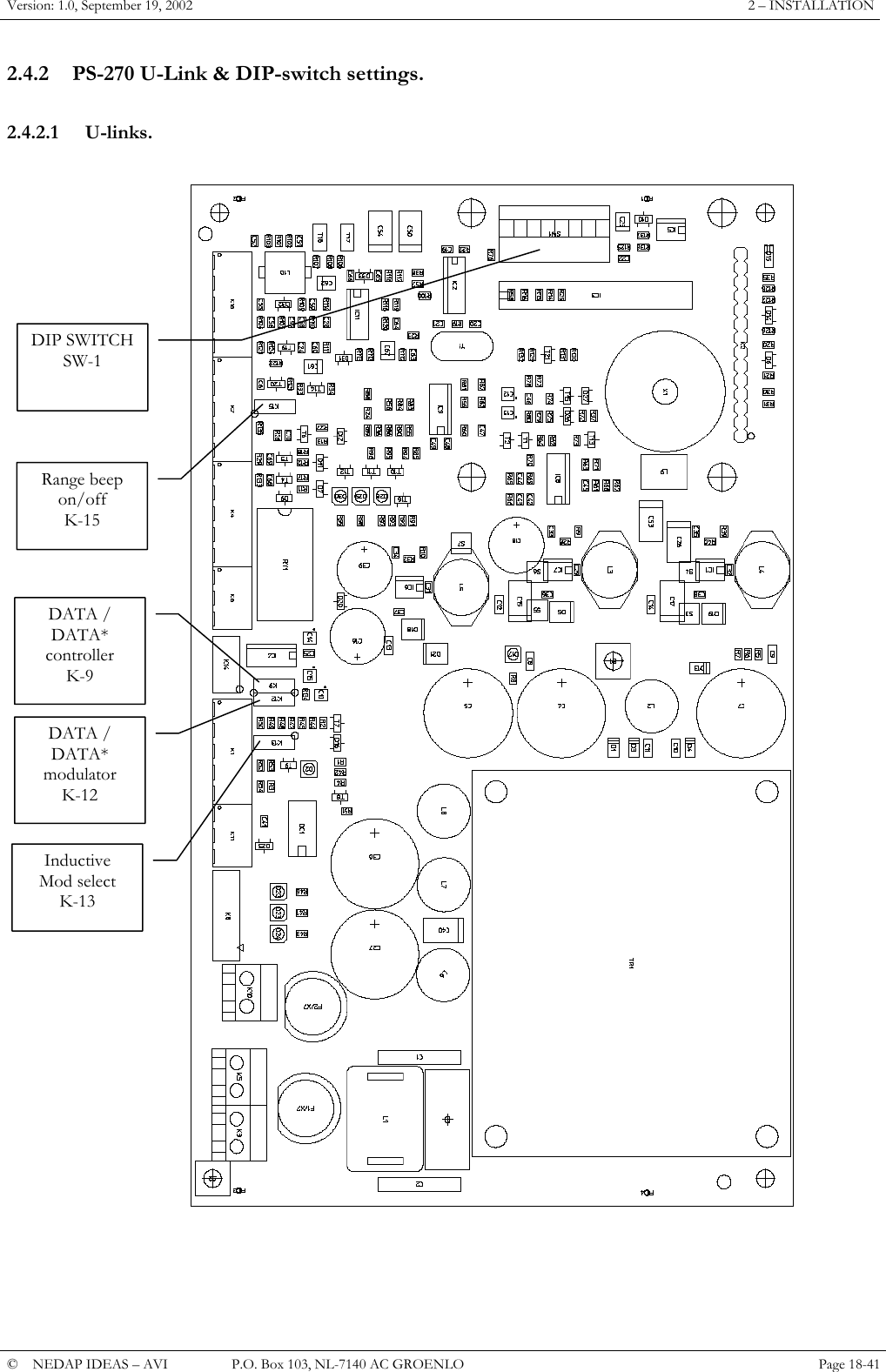
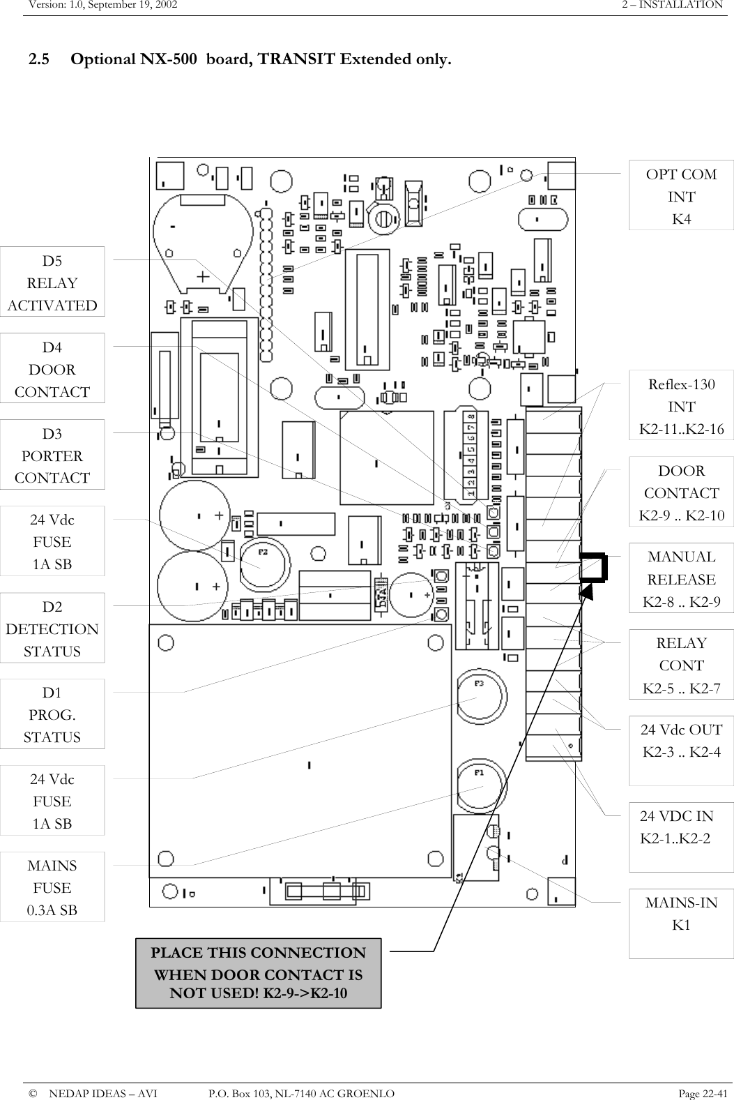
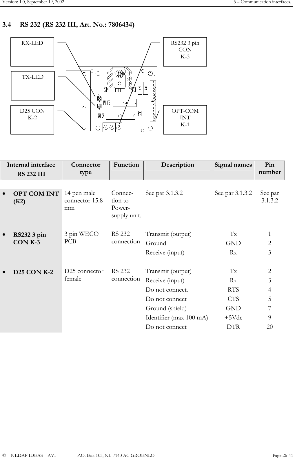
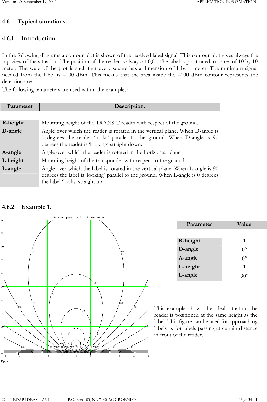
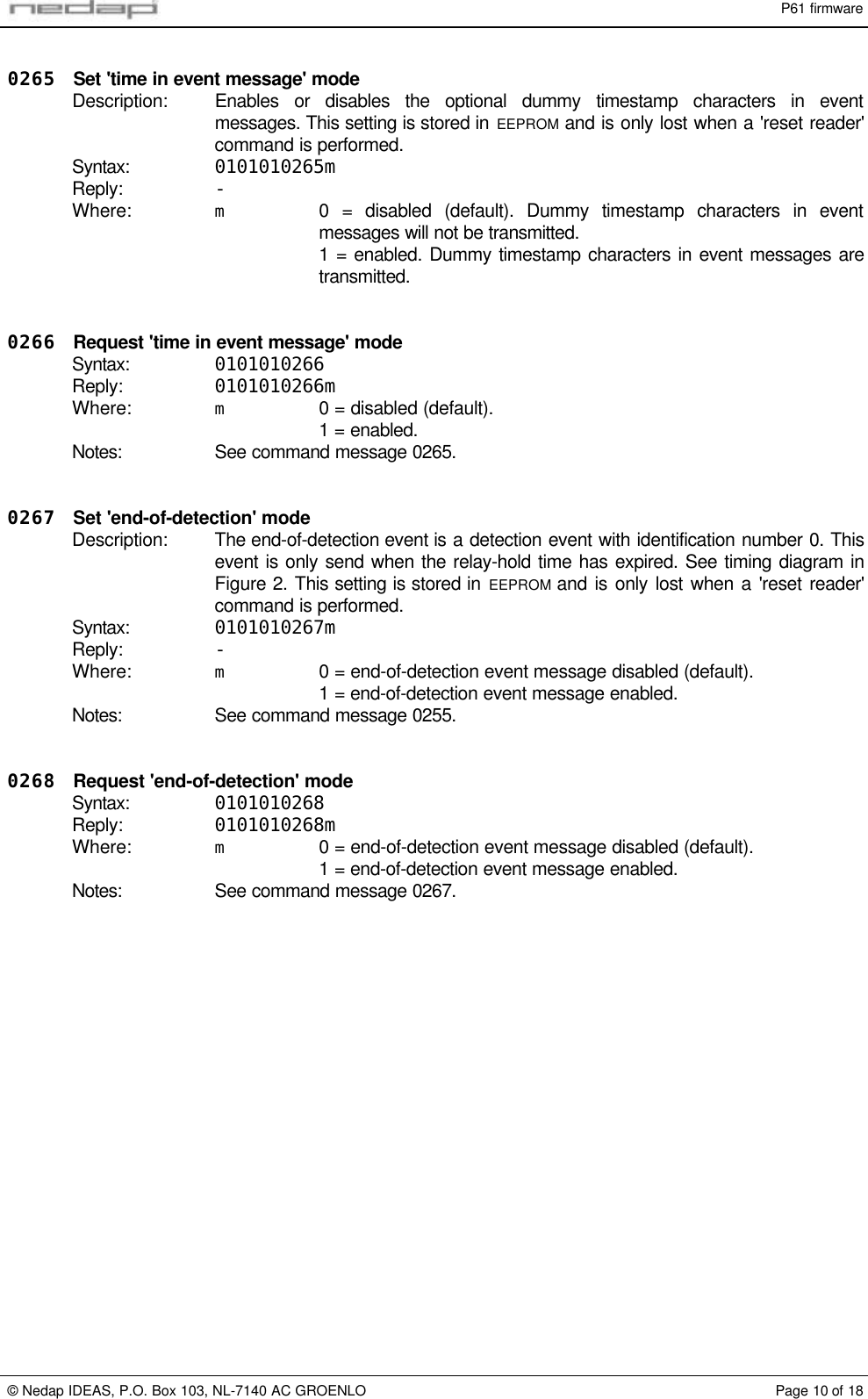
![P61 firmware© Nedap IDEAS, P.O. Box 103, NL-7140 AC GROENLO Page 7 of 18U-event: EM-Marin 400x transponder identifiedDescription: When a EM-Marin 400x transponder is identified this event message reports itsidentification number.Syntax: 01 01 01 20 U [????????] 0000000000 xxxxxxxxxxWhere: [????????]Optional unused timestamp. Can be enabled with commandmessage 0265.Notes: The EM-Marin 400x transponder may be identified by the inductive antenna (ifenabled by DIP-switch 8) or by the microwave antenna when placed in a booster.U-event: End of detectionDescription: This event message is transmitted when a previously identified transponder is nolonger present. The event is not send until the holdtime has expired.Syntax: 01 01 01 20 U [????????] 00000000000000000000Where: [????????]Optional unused timestamp. Can be enabled with commandmessage 0265.Notes: Not every detection event has to be followed by a end-of-detection event. See thetiming diagram in Figure 2.4.1.2 COMMAND MESSAGESThe following command messages may be sent to the reader. Protocol dependent characters are notshown here.20 Check communicationDescription: Command message can be used to check the communication with the TRANS-IT.The TRANS-IT will always respond with an ACK.Syntax: 01010120Reply: -0243 Request reader statusDescription: Request the current status of the reader. The reply message contains thetransponder identification number.Syntax: 0101010243Reply: 0101010243nnnnnn or 0101010243xxxxxxxxxxxxxxxxxxxxWhere: nnnnnn Identification number 6-digit in range from 0 to 999999.xxx...xxx Identification number 80 bit hexadecimal.Example1: Window-tag number 12345reply = 0101010243012345Example2: Combi-booster number 666666 with no inductive cardreply = 010101024300006666660000000000Example3: Combi-booster number 666666 with Em-Marin card 0100F246A8reply = 010101024300006666660100?246:8Example4: Booster with Em-Marin card 0100F246A8reply = 010101024300000000000100?246:80293 Request firmware versionSyntax: 0101010293Reply: 0101010293pppvvvWhere: ppp Firmware name (P61).vvv Firmware Version (100 = version 1.00).](https://usermanual.wiki/Nedap-N-V/TRANSIT/User-Guide-279257-Page-48.png)
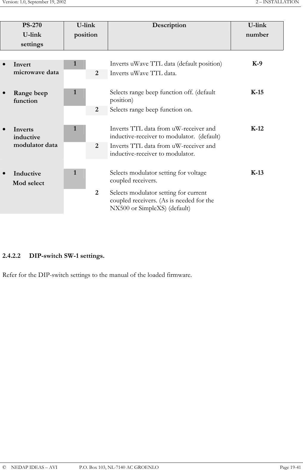
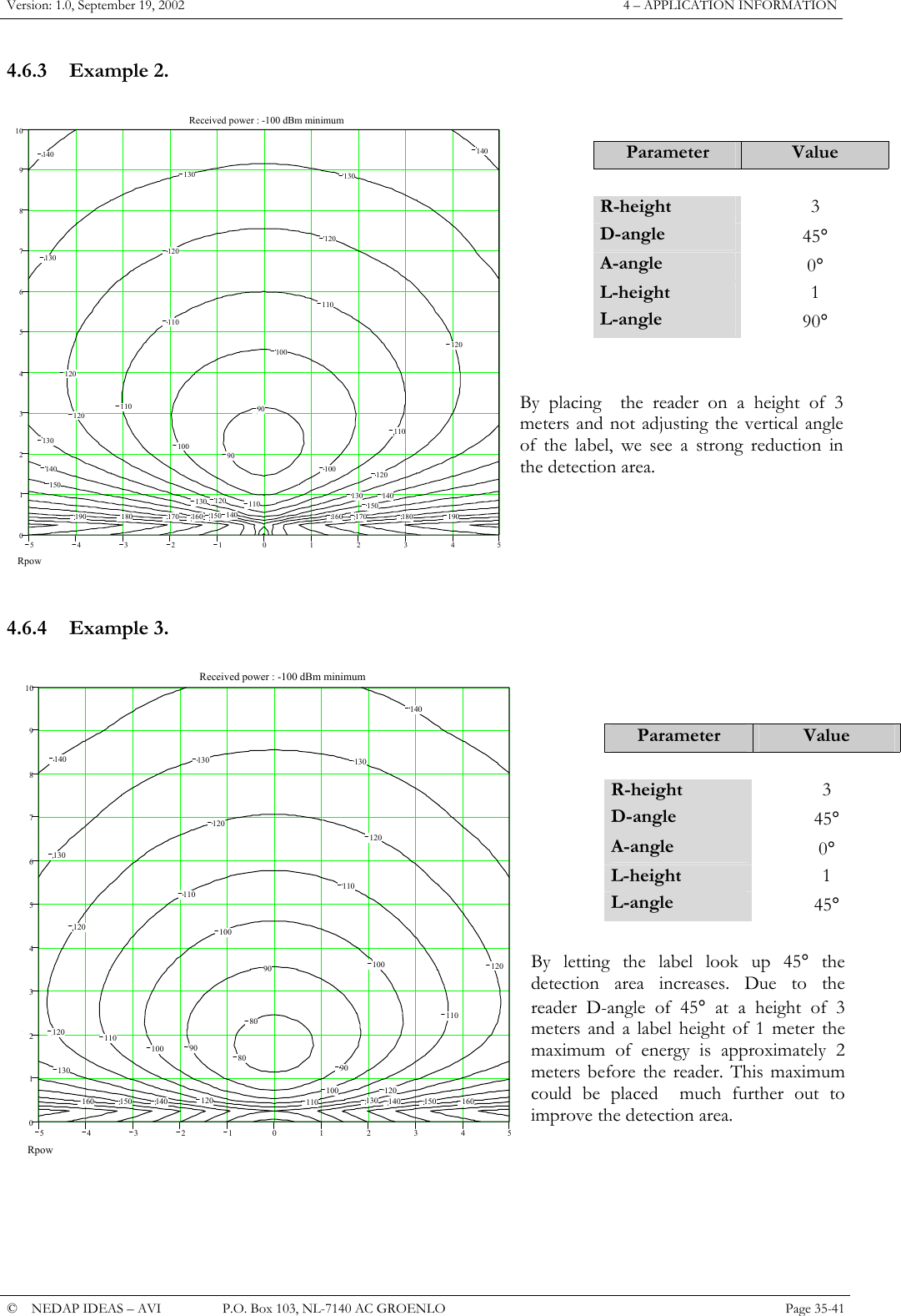
![P61 firmware© Nedap IDEAS, P.O. Box 103, NL-7140 AC GROENLO Page 8 of 180250 Clear event bufferDescription: Erase all events from the event buffer. Events are automatically erased from theevent buffer when they are transmitted to the host computer. But it may be usefulto clear the event buffer when the host computer has been offline for a while toremove 'old' events.Syntax: 0101010250Reply: -0263 Restart readerDescription: Restart the reader. This is the same as turning the power-off and back on again,and will therefore be followed by an O-event (reader restart). All EEPROM settingsare unaffected by this command.Syntax: 01010163[W]or: 0101010263[W]Reply: -Where: [W] Optional unused parameter to accept message compatible with otherNEDAP readers.Notes: See command message 02<>.02<> Reset readerDescription: Restart the reader and reset all EEPROM settings to their factory defaults. Thereader will generate a P-event (reader reset).Syntax: 01010102<>[W]Reply: -Where: WOptional unused parameter to accept messages compatible withother NEDAP readers.Notes: See command message 0263.](https://usermanual.wiki/Nedap-N-V/TRANSIT/User-Guide-279257-Page-49.png)
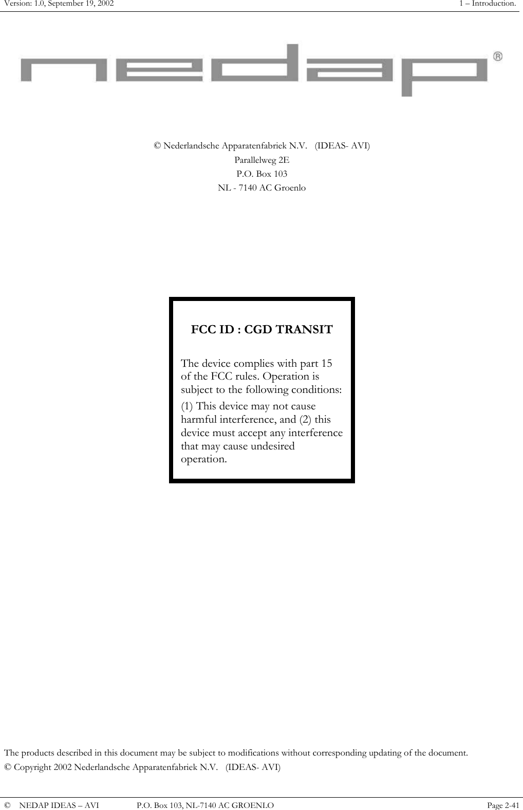
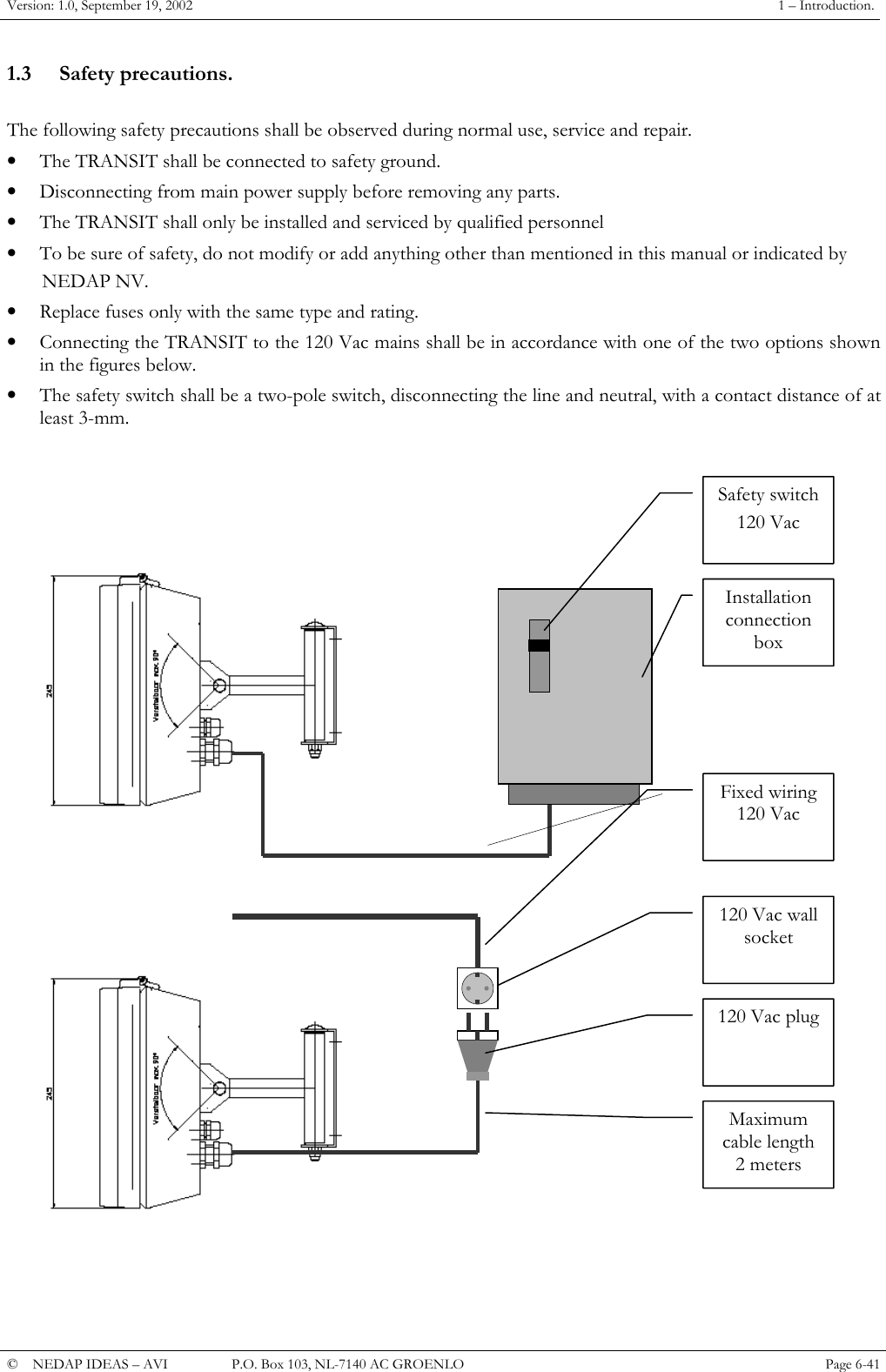
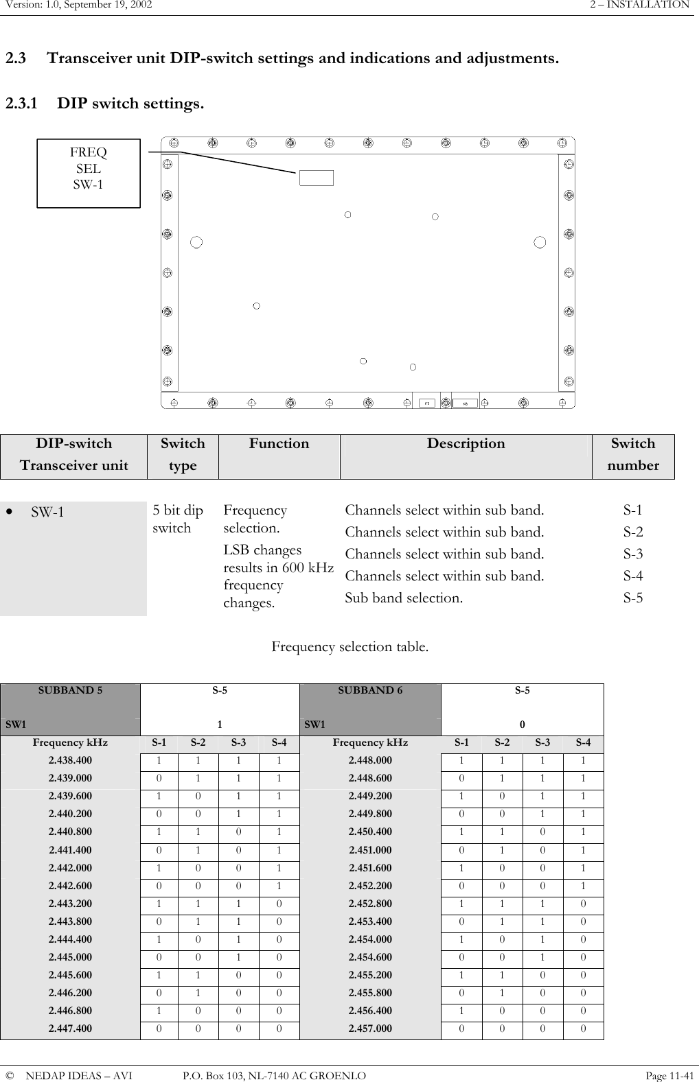
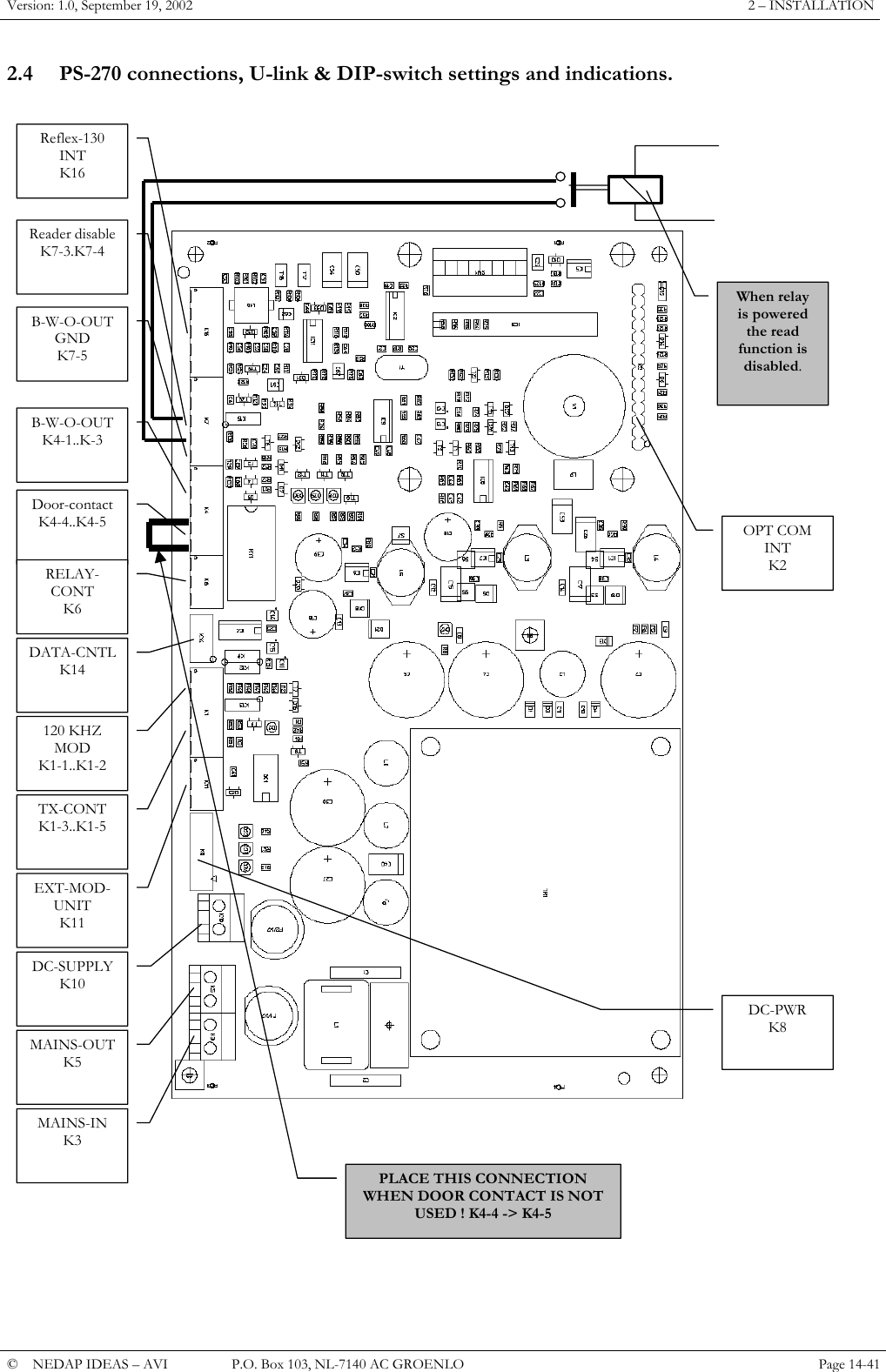
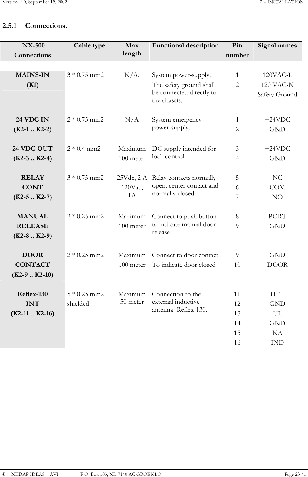
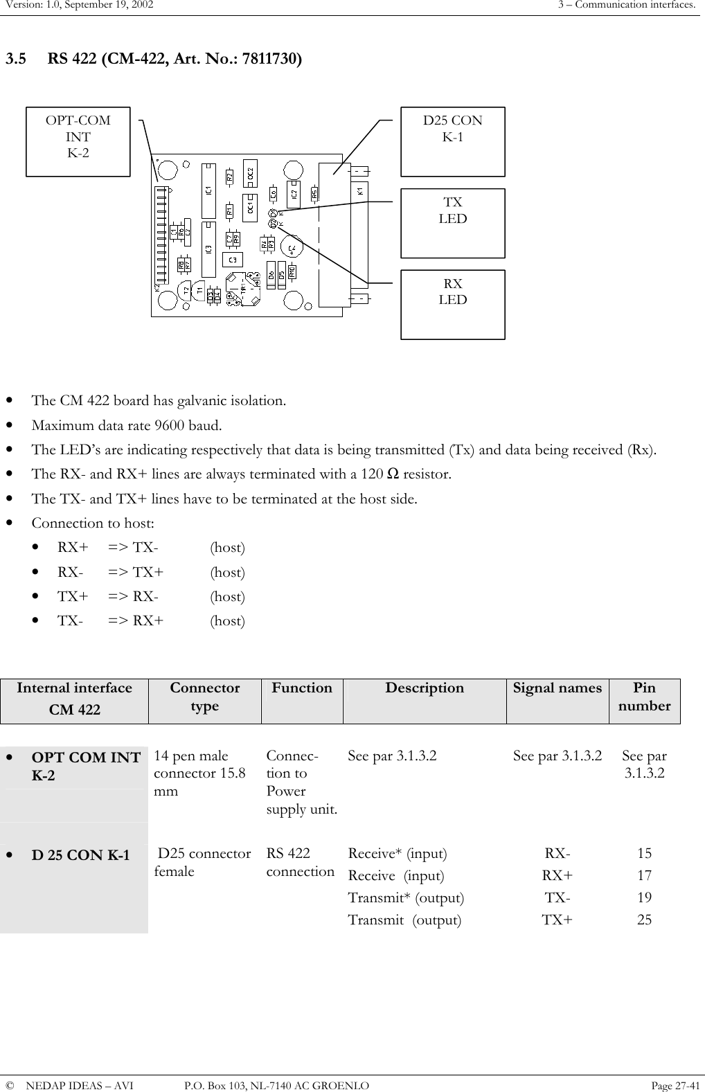
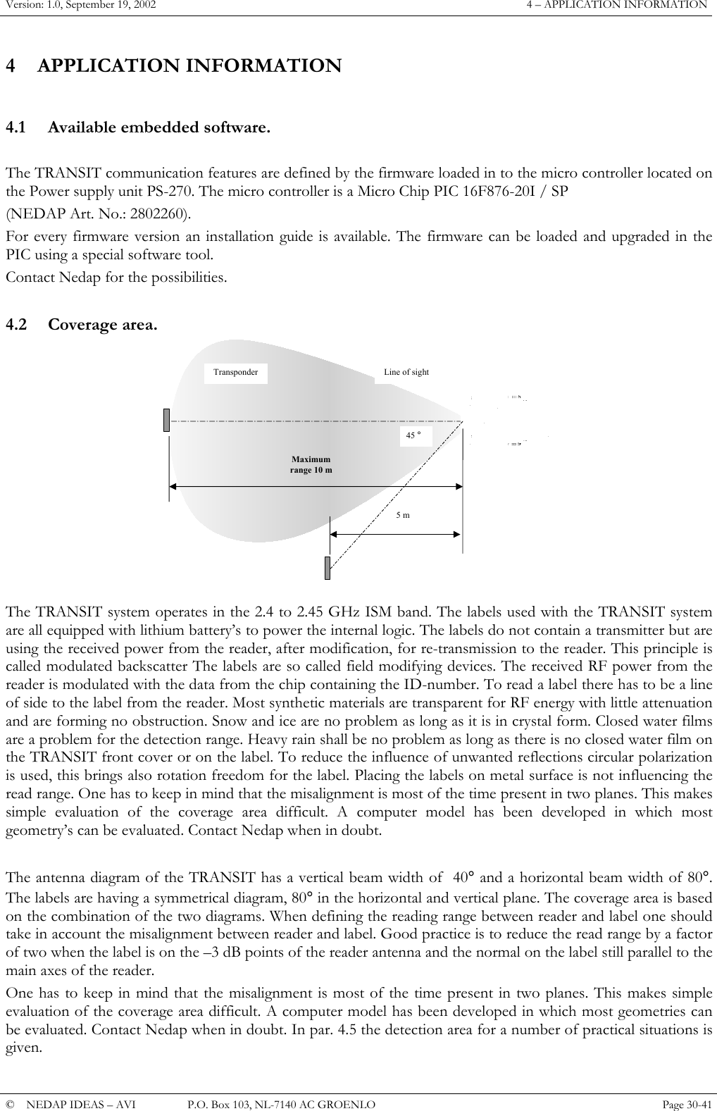
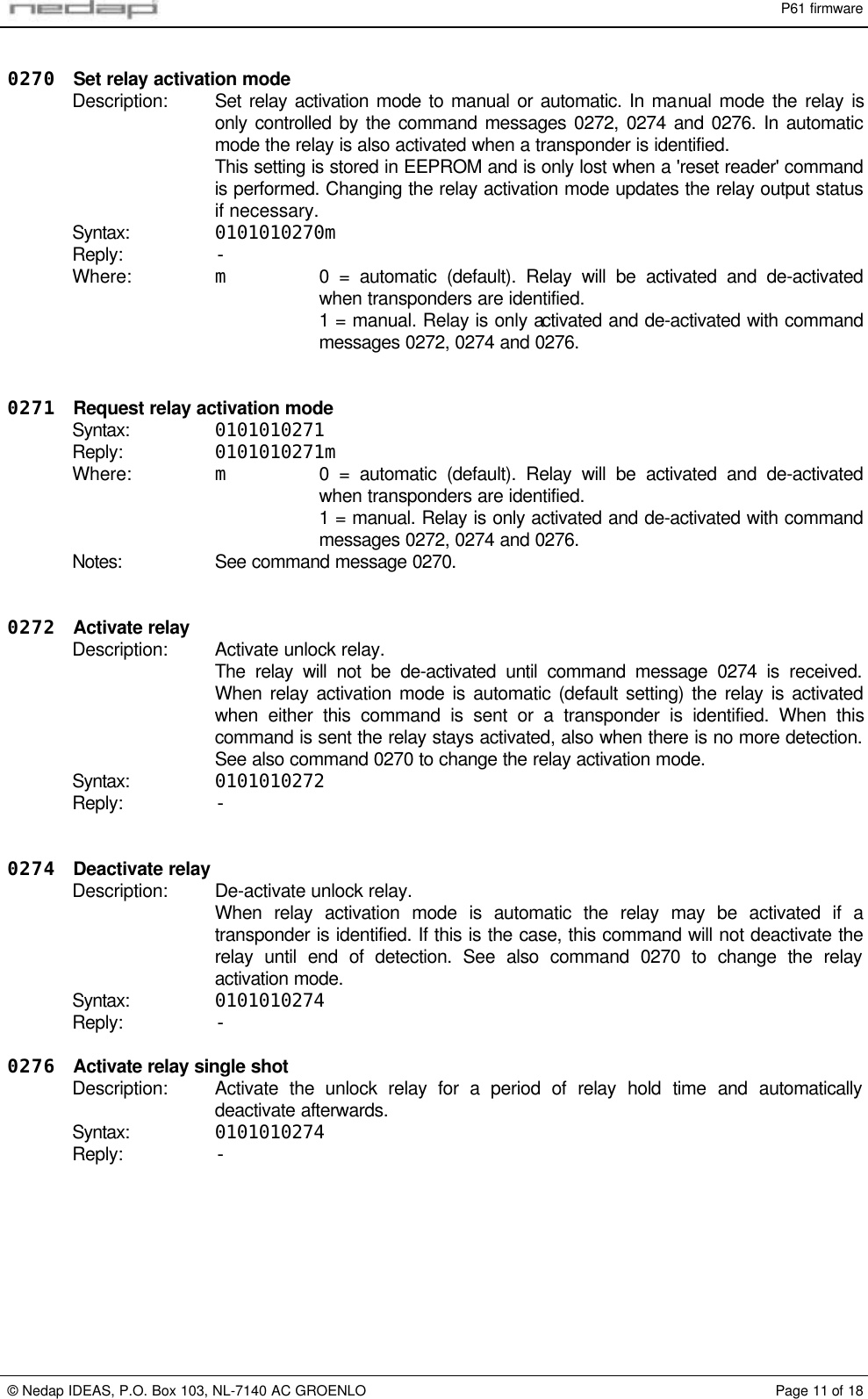
![P61 firmware© Nedap IDEAS, P.O. Box 103, NL-7140 AC GROENLO Page 9 of 180255 Request timersDescription: Request timer values. Changed timer values are stored in EEPROM and are onlylost when a 'reset reader' command is performed.The relay hold time (also referred to as the unlock-time) is default 1 second. Itcauses the unlock relay to stay activated for the specified time after thetransponder could not be identified anymore. See timing diagram in Figure 3.When during the relay hold time the same transponder is identified again thereader will not generate a new detection event.The repeat time is default 0 seconds, which means that the detection event isonly sent once. The repeat time causes the reader to transmit an detection eventevery 'repeat time' seconds for as long as the transponder is present. See timingdiagram in Figure 4.Syntax: 0101010255Reply: 0101010255AABBCCDDWhere: AA Relay hold time in the range from 1 to 255 tenths of seconds. Usedecimal to ASCII conversion table.BB Unused parameter (reserved for alarm time).CC Unused parameter (reserved for blocking time).DD Repeat time in the range from 0 to 255 tenths of seconds. Usedecimal to ASCII conversion table.DetectionHoldtimeRelayHoldtimeEvent message T-Repeat T-RepeatDetectionFigure 3: Timing diagram relay-hold-time Figure 4: Timing diagram repeat time0256 Set timersSyntax: 0101010256TTTor: 0101010256AA[BB[CC[DD]]]Reply: -Where: TTT Relay hold time in the range from 001 to 025 seconds.AA Relay hold time in the range from 1 to 255 tenths of seconds. Usedecimal to ASCII conversion table.BB Unused parameter (reserved for alarm time).CC Unused parameter (reserved for blocking time).DD Repeat time in the range from 0 to 255 tenths of seconds. Usedecimal to ASCII conversion table.Notes: See command message 0255.When only the relay hold time has to be changed, the other timer values do nothave to be specified.](https://usermanual.wiki/Nedap-N-V/TRANSIT/User-Guide-279257-Page-50.png)
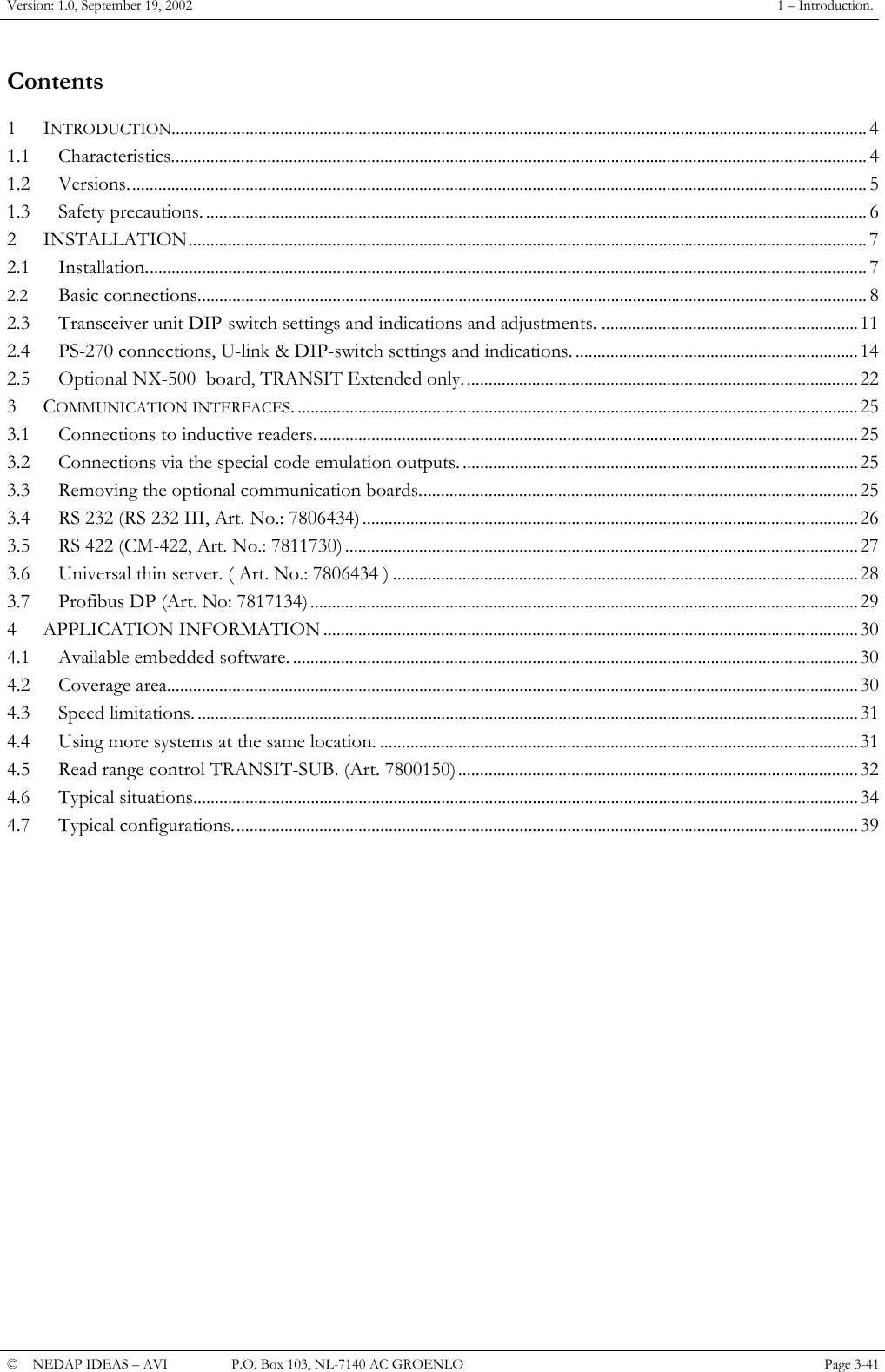
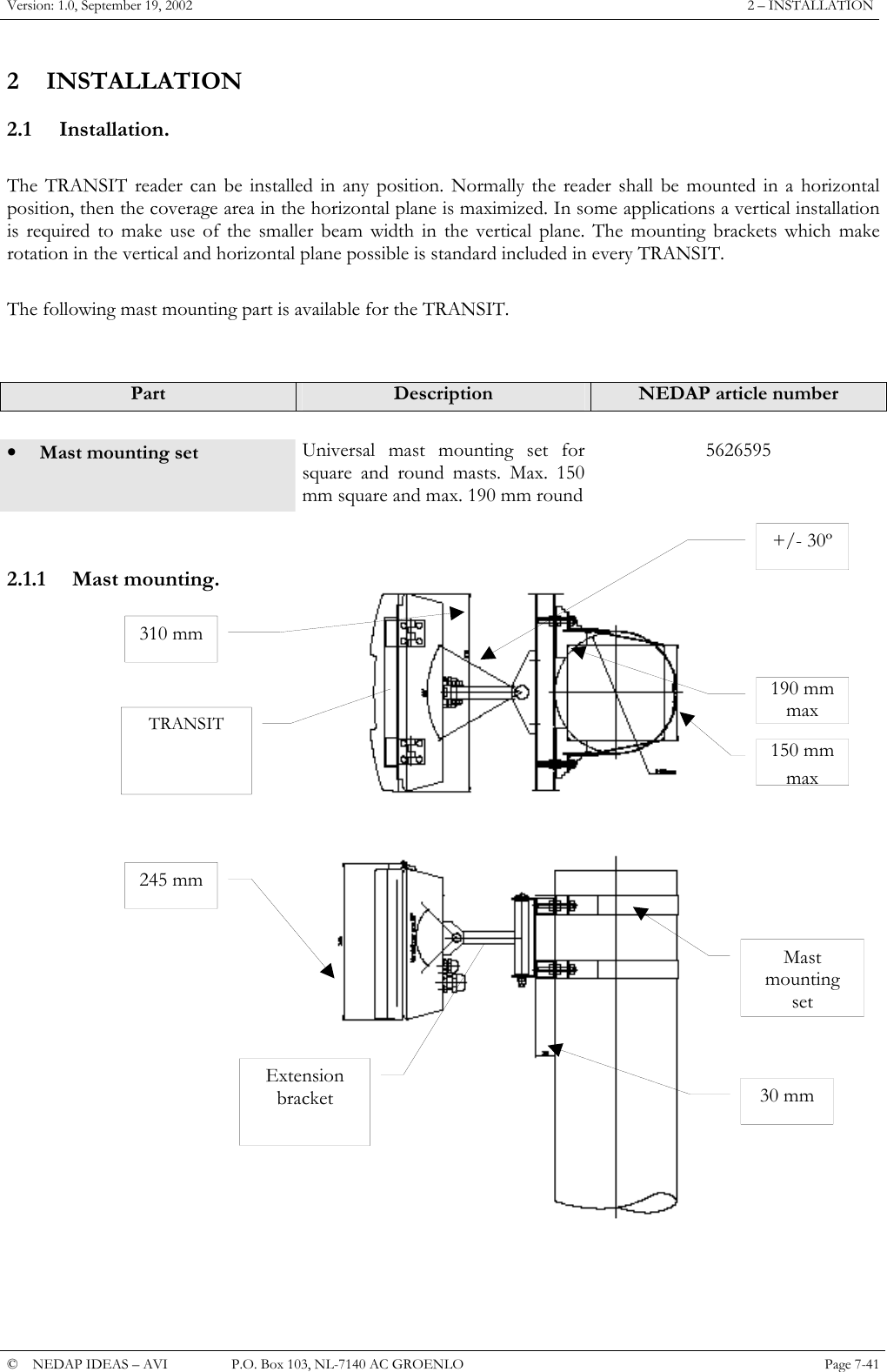
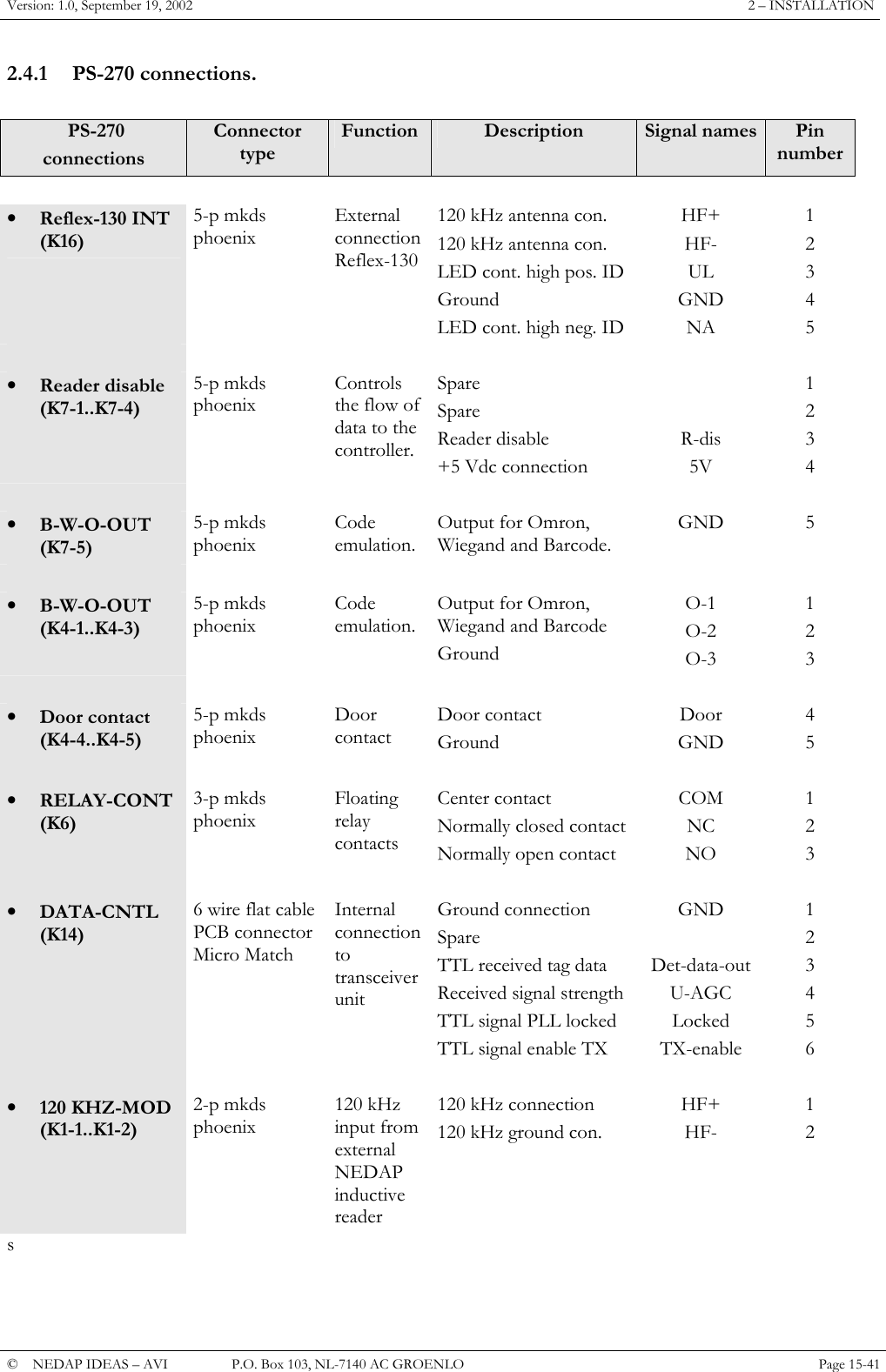
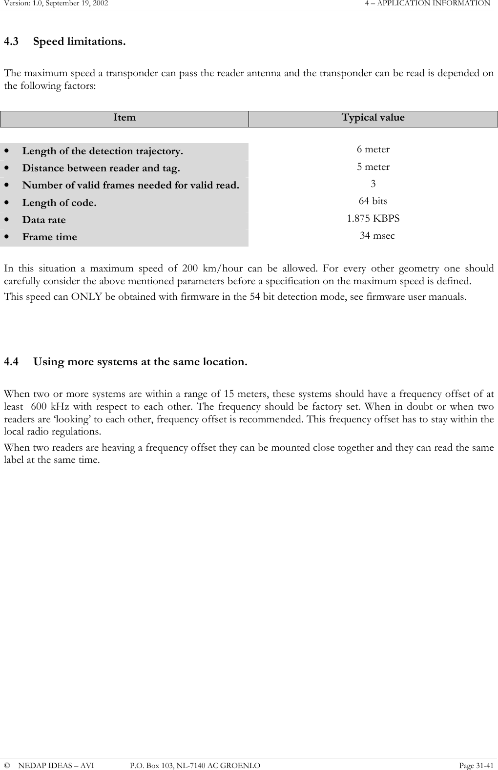
![P61 firmware© Nedap IDEAS, P.O. Box 103, NL-7140 AC GROENLO Page 14 of 18B ASCII TABLEDec Hex Char Dec Hex Char Dec Hex Char Dec Hex Char0 0 NUL 32 20 SP 64 40 @96 60 `1 1 SOH 33 21 !65 41 A97 61 a2 2 STX 34 22 "66 42 B98 62 b3 3 ETX 35 23 #67 43 C99 63 c4 4 EOT 36 24 $68 44 D100 64 d5 5 ENQ 37 25 %69 45 E101 65 e6 6 ACK 38 26 &70 46 F102 66 f7 7 BEL 39 27 '71 47 G103 67 g8 8 BS 40 28 (72 48 H104 68 h9 9 HT 41 29 )73 49 I105 69 i10 ALF 42 2A *74 4A J106 6A j11 BVT 43 2B +75 4B K107 6B k12 CFF 44 2C ,76 4C L108 6C l13 DCR 45 2D -77 4D M109 6D m14 ESO 46 2E .78 4E N110 6E n15 FSI 47 2F /79 4F O111 6F o16 10 DLE 48 30 080 50 P112 70 p17 11 DC1 49 31 181 51 Q113 71 q18 12 DC2 50 32 282 52 R114 72 r19 13 DC3 51 33 383 53 S115 73 s20 14 DC4 52 34 484 54 T116 74 t21 15 NAK 53 35 585 55 U117 75 u22 16 SYN 54 36 686 56 V118 76 v23 17 ETB 55 37 787 57 W119 78 w24 18 CAN 56 38 888 58 X120 78 x25 19 EM 57 39 989 59 Y121 79 y26 1A SUB 58 3A :90 5A Z122 7A z27 1B ESC 59 3B ;91 5B [123 7B {28 1C FS 60 3C <92 5C \124 7C |29 1D GS 61 3D =93 5D ]125 7D }30 1E RS 62 3E >94 5E ^126 7E ~31 1F US 63 3F ?95 5F _127 7F DEL](https://usermanual.wiki/Nedap-N-V/TRANSIT/User-Guide-279257-Page-55.png)
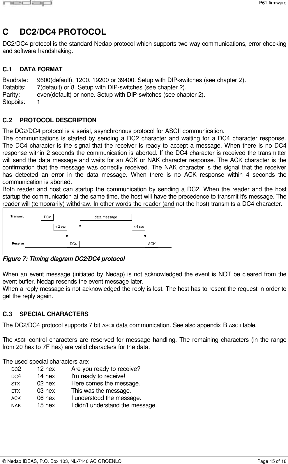
![P61 firmware© Nedap IDEAS, P.O. Box 103, NL-7140 AC GROENLO Page 16 of 18C.4 DATA MESSAGEThe data message is built up as follows:STX <ADDR> FF [ff] [data] <cc> ETXWhere: STX STX character.<ADDR> Address. For P61 firmware always '010101'.FF Two character command number. See chapter 4.1.2.[ff] Optional two character sub command number. See chapter 4.1.2.[data] Optional data.<cc> Two bytes checksum.ETX ETX character.C.5 CHECKSUM CALCULATIONThe checksum is calculated following the procedure below:1. Sum all character values in the message. STX, ETX and the checksum itself not included.2. This sum must be shortened into 1 byte.3. Split this byte up into two bytes.4. Finally add the value of character '0' to both bytes to make sure the checksum does not contain controlcharacters.Example:message = '0101010293'ASCII characters are enclosed within quotes, all other values are in hexadecimal notation:1. Sum all character values: 4 x '0' + 3 x '1' + '2' + '9' + '3' = 4 x 30 + 3 x 31 + 32 + 39 + 33 = 1F1.2. Shorten sum into 1 byte: F1.3. Split byte into 2 bytes: 0F and 01.4. Add '0' to both bytes: 0F + '0' = 0F + 30 = 3F = '?' and 01 + '0' = 01 + 30 = 31 = '1'.Complete message = STX'0101010293?1'ETX](https://usermanual.wiki/Nedap-N-V/TRANSIT/User-Guide-279257-Page-57.png)