Nedap N V TRANSITULT2 Long-range vehicle and driver identification reader User Manual 253115X
N. V. Nederlandsche Apparatenfabriek NEDAP Long-range vehicle and driver identification reader 253115X
Contents
- 1. Users manual
- 2. Users Manual
Users manual
TRANSIT ULTIMATE
installation guide
2017-08-17 | v5.01 | 5481104

TRANSIT ULTIMATE | INSTALLATION GUIDE
Content
2/36
CONTENT
1.
INTRODUCTION _______________________________________________________ 3
1.1
PRODUCT DESCRIPTION __________________________________________ 3
1.2
ULTIMATE FEATURES _____________________________________________ 4
2.
INSTALLATION ________________________________________________________ 5
2.1
SAFETY PRECAUTIONS ___________________________________________ 5
2.2
INSTALLATION GUIDELINES _______________________________________ 5
2.3
MOUNTING INSTRUCTIONS _______________________________________ 6
2.3.1
TRANSIT ULTIMATE DIMENSIONS ____________________________ 6
2.3.2
WALL MOUNTING _________________________________________ 7
2.3.3
POLE MOUNTING__________________________________________ 8
2.3.4
WEATHER PROTECTION HOOD ______________________________ 9
2.4
INSTALLING THE SECURITY KEY PACK _____________________________ 10
2.5
INSTALLING A COMMUNICATION BOARD ___________________________ 11
3.
CONNECTIONS _______________________________________________________ 12
3.1
OVERVIEW ____________________________________________________ 12
3.2
POWER SUPPLY ________________________________________________ 13
3.2.1
AC MAINS _______________________________________________ 13
3.2.2
DC SUPPLY INPUT ________________________________________ 13
3.2.3
DC OUTPUT _____________________________________________ 14
3.3
COMMUNICATION ______________________________________________ 15
3.3.1
USB ____________________________________________________ 15
3.3.2
WIEGAND / MAGSTRIPE / BARCODE _________________________ 16
3.3.3
RS232 COMMUNICATION _________________________________ 17
3.3.4
RS422 COMMUNICATION _________________________________ 17
3.4
DIGITAL I/O ____________________________________________________ 18
3.4.1
RELAY OUTPUT __________________________________________ 18
3.4.2
READ DISABLE INPUT _____________________________________ 19
3.4.3
TAMPER SWITCH _________________________________________ 20
3.4.4
GENERAL PURPOSE INPUTS ________________________________ 21
3.5
SPECIAL CONNECTIONS _________________________________________ 22
3.5.1
PROXIMITY ANTENNA _____________________________________ 22
3.5.2
NEDAP ANTENNA MODULATION ____________________________ 23
4.
CONFIGURATION _____________________________________________________ 24
4.1
FIRMWARE OPTIONS ____________________________________________ 24
4.2
SERIAL COMMUNICATION SELECT _________________________________ 24
4.3
ULTIMATE-MODE _______________________________________________ 25
4.4
RANGE BEEPER_________________________________________________ 25
4.5
FREQUENCY SELECTION _________________________________________ 26
4.5.1
FREQUENCY SELECT DISPLAY & BUTTONS ___________________ 26
4.5.2
FREQUENCY SELECT DIP-SWITCHES _________________________ 26
4.6
READ RANGE CONTROL _________________________________________ 27
4.7
MICROWAVE TIME-SHARING _____________________________________ 28
5.
LED INDICATIONS ____________________________________________________ 29
5.1
MAIN BOARD INDICATIONS ______________________________________ 29
5.2
TAB BOARD INDICATIONS ________________________________________ 30
A
TECHNICAL SPECIFICATIONS ___________________________________________ 31
B
FREQUENCY CHANNELS _______________________________________________ 32
C
NEDAP PART NUMBERS ________________________________________________ 33
D
FCC / IC STATEMENT __________________________________________________ 34
E
DISCLAIMER _________________________________________________________ 35
F
DOCUMENT REVISION _________________________________________________ 36

TRANSIT ULTIMATE | INSTALLATION GUIDE
INTRODUCTION
3/36
1. INTRODUCTION
1.1
PRODUCT DESCRIPTION
The TRANSIT Ultimate is a long-range reader, based on semi active RFID technology,
which enables automatic vehicle identification at distances of up to 10 meters (33
ft.) and speeds of up to 200 km/h (125 mph).
Key features
Robust industrial design
Read range up to 10 meters [33 ft.]
Object speed up to 200 km/h [125 mph]
Adjustable read range
Selectable frequency channels
Variety of integrated communication interfaces
3 color LED indication
Tag authentication based on AES encryption
Bi-directional tag communication
Backwards-compatible with previous TRANSIT readers.
Frequency channels
The TRANSIT Ultimate operates on a factory-set frequency channel. Different
frequency channels allow multiple readers to operate in close vicinity of each other
without interference.
Read range adjustment
The reader efficiently resolves typical multi-lane, entry and exit reader challenges.
The read range of the TRANSIT Ultimate can be adjusted to offer secure and reliable
identification in demanding applications.
Housing & mounting
The TRANSIT Ultimate is intended for outdoor installation.
The weatherproof TRANSIT Ultimate reader features an IP66 certified housing. The
reader operates reliable under harsh environmental conditions and is able to
withstand exposure to rain, snow and ice. Wall mounting equipment is included.
Interfaces & protocols
The TRANSIT Ultimate is designed for seamless and flexible integration into existing
management systems in the industry, such as security, parking, and logistics. Several
communication interfaces to the host system are available such as RS232, RS422,
RS485, Profibus-DP and TCP/IP. Also open industry-standards protocols such as
Wiegand, Magstripe and Barcode are supported. Customer specific protocols can be
implemented on request.
TRANSIT ULTIMATE | INSTALLATION GUIDE
INTRODUCTION
4/36
1.2
ULTIMATE FEATURES
Encrypted tag authentication
The TRANSIT Ultimate enables encrypted tag authentication for the Ultimate tags:
Smartcard Booster Ultimate, LEGIC Booster Ultimate and Window Tag Ultimate. The
authentication uses encryption based upon AES 128-bit keys. Key diversification is
used to ensure that a unique encryption key is used for every tag.
Data storage
Thanks to the bi-directional tag communication feature and in combination with
Smartcard-Booster Ultimate it will be possible to write information on the drivers’
access control card when the car enters or leaves a perimeter. This will enable write
actions like changing credits, offline access rights or other information changes
dynamically upon perimeter access.
Implementation
The Ultimate-mode features are implemented in the TAB board. The TAB-board
performs the authentication or other Ultimate function using the bi-directional tag
communication channel at 433MHz.
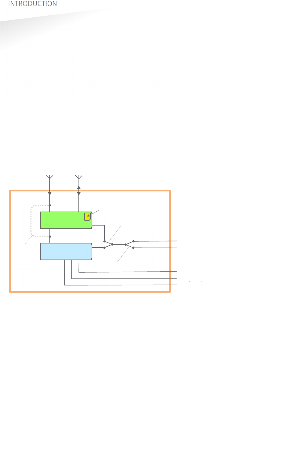
Figure 1: TRANSIT Ultimate block diagram
Authentication procedure
The encrypted tag authentication is performed when both antennas (433MHz and
2.45GHz) receive the same id-number. This ensures that the tag to be authenticated
is located in the well-defined directional beam in front of the reader.
1. Receive Ultimate tag id-number.
2. Send encrypted challenge to the tag.
The challenge is generated by the Security Key Pack based upon random
numbers encrypted with a diversified AES128 key.
3. Receive, decrypt and verify the encrypted challenge response from the tag.
4. When the authentication is successful, the id-number is transmitted on the
communication output(s). Wiegand, USB, etc.
TRANSIT - PIC
2.45GHz 433MHz
Ultimate
mode
bypass
Serial com-select
USB-detect
USB
I/F-board
Wiegand
Relay output
Smiley RGB
TAB-board
Security Key Pack
TRANSIT Ultimate
Note
The TAB board may be
bypassed to make the
TRANSIT Ultimate fully
compatible with the
TRANSIT Standard. See
chapter 4.3.
TRANSIT ULTIMATE | INSTALLATION GUIDE
INSTALLATION
5/36
2. INSTALLATION
2.1
SAFETY PRECAUTIONS
The following safety precautions should be observed during normal use, service and
repair:
The TRANSIT Ultimate shall be connected to safety ground.
Disconnecting from (mains) power supply before removing any parts.
The TRANSIT Ultimate shall only be installed and serviced by qualified service
personnel.
To be sure of safety, do not modify or add anything other than mentioned in this
manual or indicated by NEDAP N.V.
2.2
INSTALLATION GUIDELINES
The TRANSIT Ultimate can be installed in any position. The normally expected read
range is up to 10 meters.
Usually the reader is mounted in the horizontal position. In this case the coverage
area in the horizontal plane is maximized. The horizontal beam is 80 degrees.
Horizontal mounting: 80 degrees wide read coverage.
In some applications a vertical installation is required to make use of the smaller
beam width in the vertical plane. The vertical beam is 40 degrees. This can be very
useful in applications with multiple driving lanes to prevent cross readings.
Vertical mounting: 40 degrees narrow read coverage.
The Wall Mounting Set, which make rotation in the vertical and horizontal plane
possible, is standard included with every TRANSIT Ultimate.
TRANSIT ULTIMATE | INSTALLATION GUIDE
INSTALLATION
6/36
2.3
MOUNTING INSTRUCTIONS
See the following chapters for details about the dimensions of the reader and the
mounting brackets and the locations of the mounting positions.
2.3.1
TRANSIT ULTIMATE DIMENSIONS
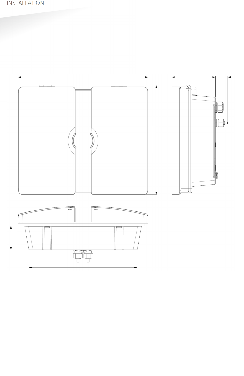
The picture below shows the dimensions of the TRANSIT Ultimate.
All dimensions are in mm.
Figure 2: Dimensions TRANSIT Ultimate
326 mm 109 mm 31
271 mm
60 mm
274 mm
TRANSIT ULTIMATE | INSTALLATION GUIDE
INSTALLATION
7/36
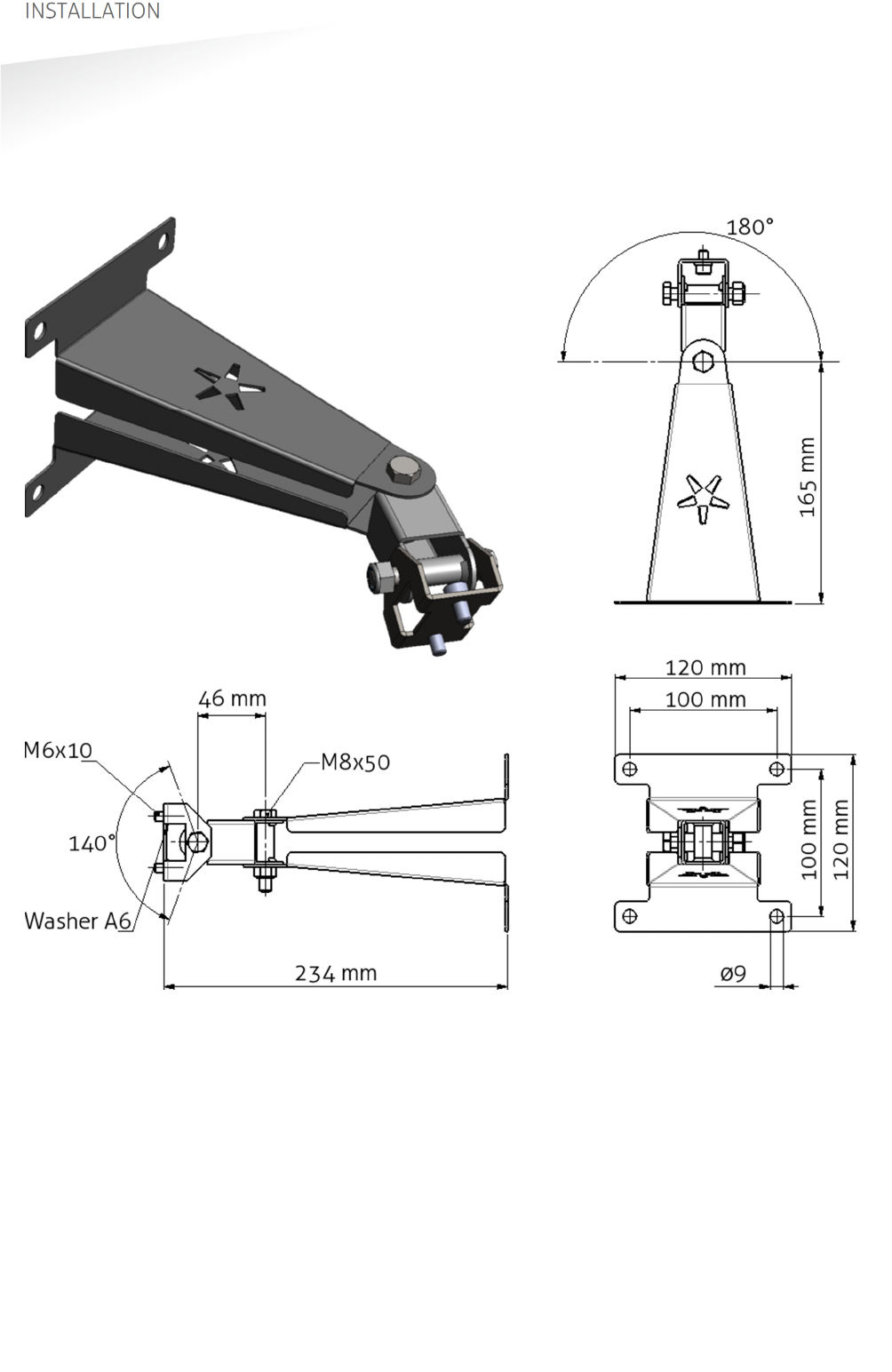
2.3.2
WALL MOUNTING
The Wall Mounting Set is supplied with the TRANSIT Ultimate reader. When the Wall
Mounting Set is assembled mount it to the wall (or to the Pole Mounting Set) based
on the dimensions in Figure 3. The TRANSIT Ultimate can be “aimed” with the Wall
Mounting Set and when the bolts are tightened, it will stay in place.
Figure 3: Wall Mounting Set
TRANSIT ULTIMATE | INSTALLATION GUIDE
INSTALLATION
8/36
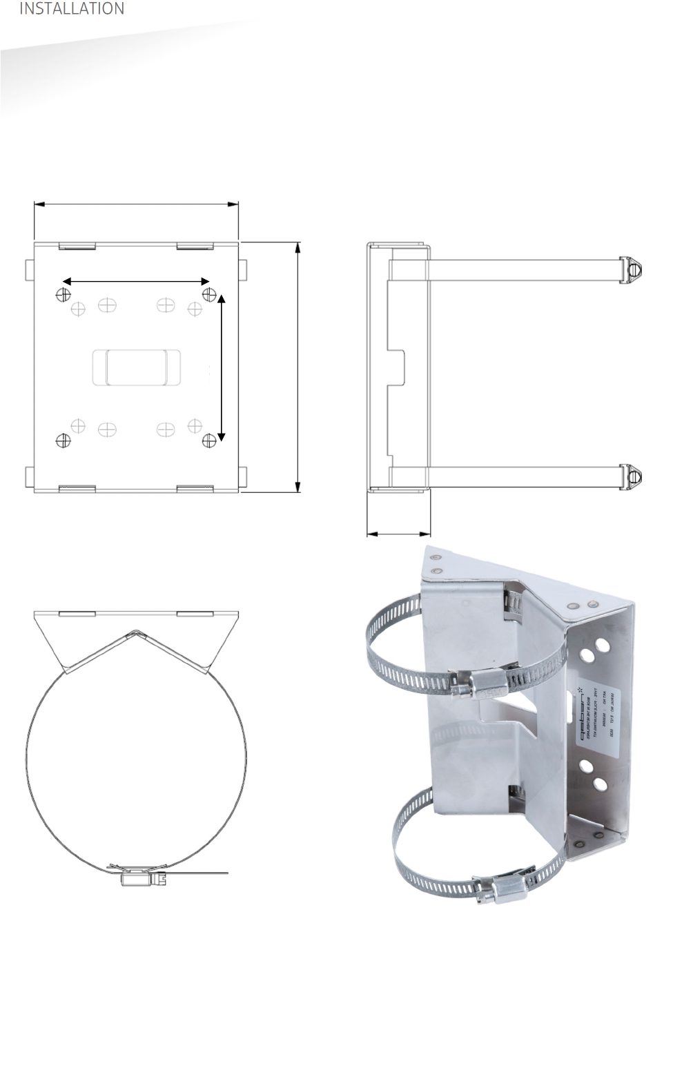
2.3.3
POLE MOUNTING
The Pole Mounting Kit has to be ordered separately (art. no. 5626595).
The TRANSIT Ultimate can be mounted to round poles with maximum diameter of
190 mm and square poles with maximum diameter of 150 mm using the Pole
Mounting Kit.
Note that the Wall Mounting Set will be mounted onto the Pole Mounting Kit.
Figure 4: Dimensions Pole Mounting Kit
140 mm
172 mm
43 mm
100 mm
100 mm
TRANSIT ULTIMATE | INSTALLATION GUIDE
INSTALLATION
9/36
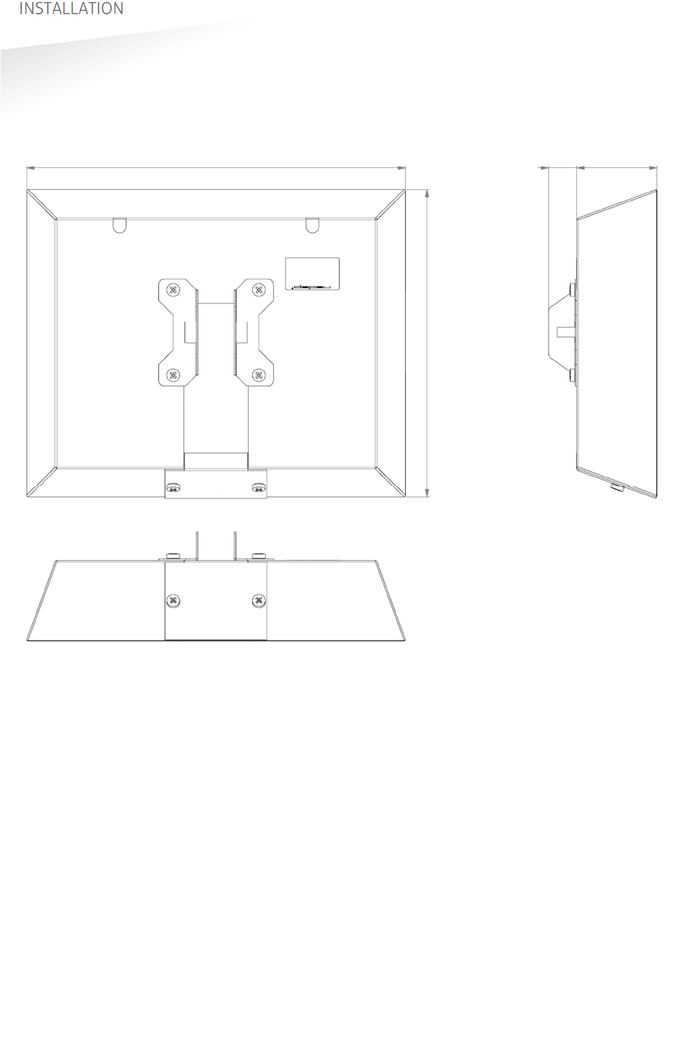
2.3.4
WEATHER PROTECTION HOOD
The Weather Protection Hood has to be ordered separately (art. no. 9218327).
It is recommended when the reader is installed in places where direct sunlight may
overheat the reader.
Figure 5: Dimensions Weather Protection Hood
354 mm 27 mm 75 mm
287 mm
TRANSIT ULTIMATE | INSTALLATION GUIDE
INSTALLATION
10/36
2.4
INSTALLING THE SECURITY KEY PACK
The optional Security Key Pack (SAM) has to be ordered separately (art. no. 9216537)
and is required for the TRANSIT Ultimate to perform the encrypted authentication on
the Ultimate tags. Please follow the procedure below to install the Security Key Pack
into the TRANSIT Ultimate.
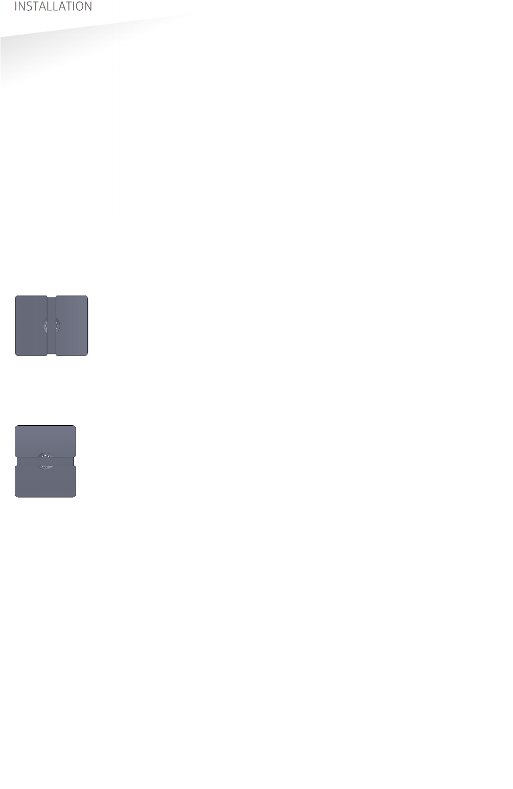
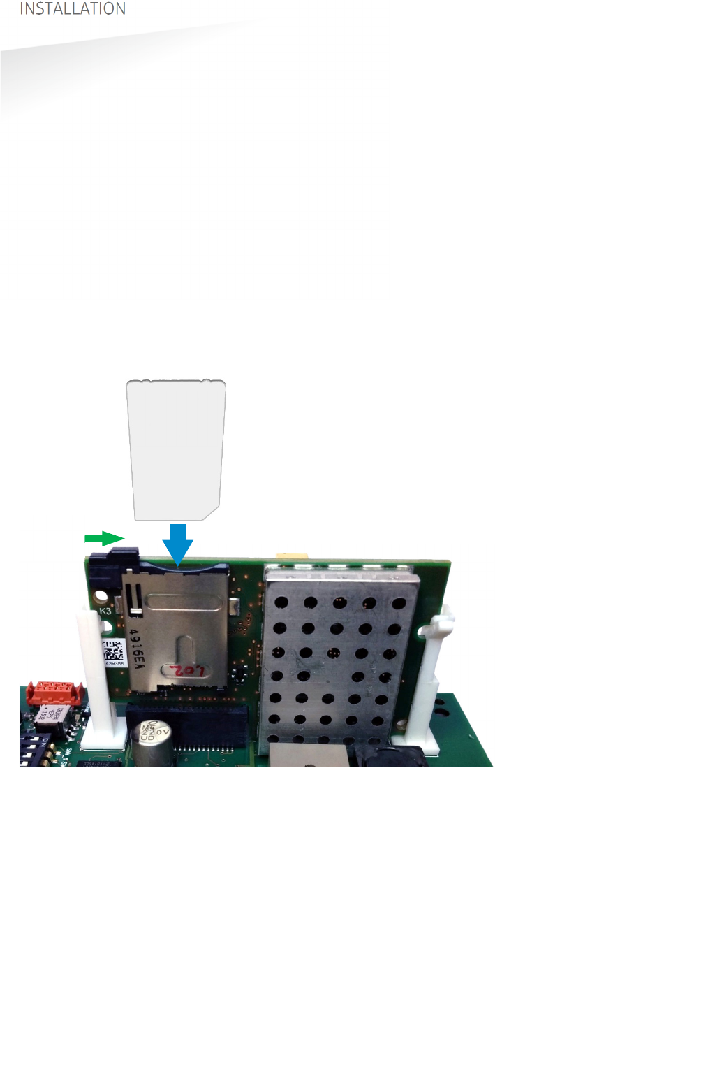
Security Key Pack installation procedure
Insert the Security Key Pack (SAM) into the TAB board.
1. Align the notch as indicated in Figure 6 and keep the metal contacts backwards.
2. Push the SAM into the slot until it clicks into place.
3. Set the LOCK-switch to the right to lock the SAM.
4. Enable the Ultimate-mode by settings dip-switch SW2-2 ON. See chapter 4.3.
Removal procedure
1. Set the LOCK-switch to the left to release the SAM.
2. Push the SAM to eject it.
3. Disable the Ultimate-mode by setting dip-switch SW2-2 OFF. See chapter 4.3.
Figure 6: Installing the Security Key Pack (SAM)
SAM
LOCK

TRANSIT ULTIMATE | INSTALLATION GUIDE
INSTALLATION
11/36
2.5
INSTALLING A COMMUNICATION BOARD
The TRANSIT Ultimate features an on-board USB port and a Wiegand / Magstripe /
Barcode interface. See chapter 3.3 for more details.
Other communication interfaces can modularly be installed in the reader by means
of a communication interface board. There are various communication interface
boards available for the TRANSIT Ultimate. See appendix C for available boards and
their part numbers.
Make sure to follow all safety precautions outlined in chapter 2.1 when installing or
replacing a communication board.
Communication board installation procedure:
1. Open the TRANSIT Ultimate. You can put the cover strut into place to keep the
cover open.
2. Disconnect the power supply.
3. Place the communication interface board on the 14-pin header K5 as indicated
in the picture below.
4. Make sure that the 4 plastic PCB supports are properly positioned and fixed into
the communication board.
5. Read the communication board’s installation guide for additional notes like
address setting, jumper settings and wiring details.
6. Test if the communication works correctly.
7. Close the cover of the TRANSIT Ultimate.
TRANSIT ULTIMATE | INSTALLATION GUIDE
CONNECTIONS
12/36
3. CONNECTIONS
3.1
OVERVIEW
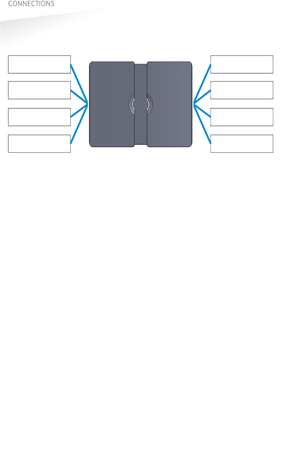
Figure 7: TRANSIT Ultimate connections overview
Power supply
See chapter 3.2
Read-disable input
See chapter 3.4.2
General purpose inputs
See chapter 3.4.4
Proximity antenna
See chapter 3.5.1
Relay output
See chapter 3.4.1
Tamper switch
See chapter 3.4.3
Communication
See chapter 3.3
Antenna modulation
See chapter 3.5.2
TRANSIT ULTIMATE | INSTALLATION GUIDE
CONNECTIONS
13/36
3.2
POWER SUPPLY
The TRANSIT Ultimate can be powered by AC mains or by a 24 VDC power supply.
3.2.1
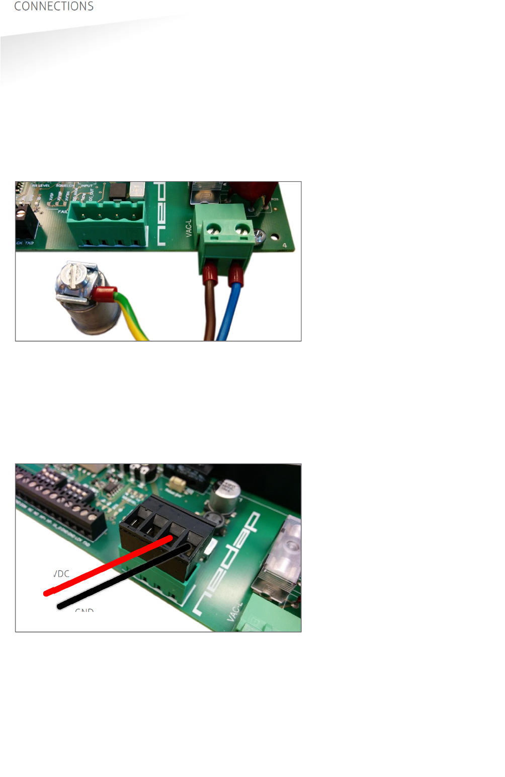
AC MAINS
Connect the Mains load and neutral wires to the connector terminals VAC-L and
VAC-N. The earth wire should be connected to the dedicated safety ground
connection.
Input voltage: 100 – 240 VAC
Frequency: 60 – 50 Hz.
Figure 8: AC mains connections
3.2.2
DC SUPPLY INPUT
Connect the DC power supply to the connector terminals as indicated below.
Remove the connector for easy fixing the wires.
Input voltage: 24 VDC ± 10%
Max. input current: 700 mA @ 24 VDC
Figure 9: DC input connections
GND
+24VDC
VAC-L VAC-N
GROUND

TRANSIT ULTIMATE | INSTALLATION GUIDE
CONNECTIONS
14/36
3.2.3
DC OUTPUT
The DC output can be used to supply power to an additional device installed inside
or near the TRANSIT Ultimate.
Figure 10: DC output connections
DC output ratings
Output voltage: 23.4 VDC ± 10%
Max. output current: 100 mA.
GND
+DC-OUT
TRANSIT ULTIMATE | INSTALLATION GUIDE
CONNECTIONS
15/36
3.3
COMMUNICATION
3.3.1
USB
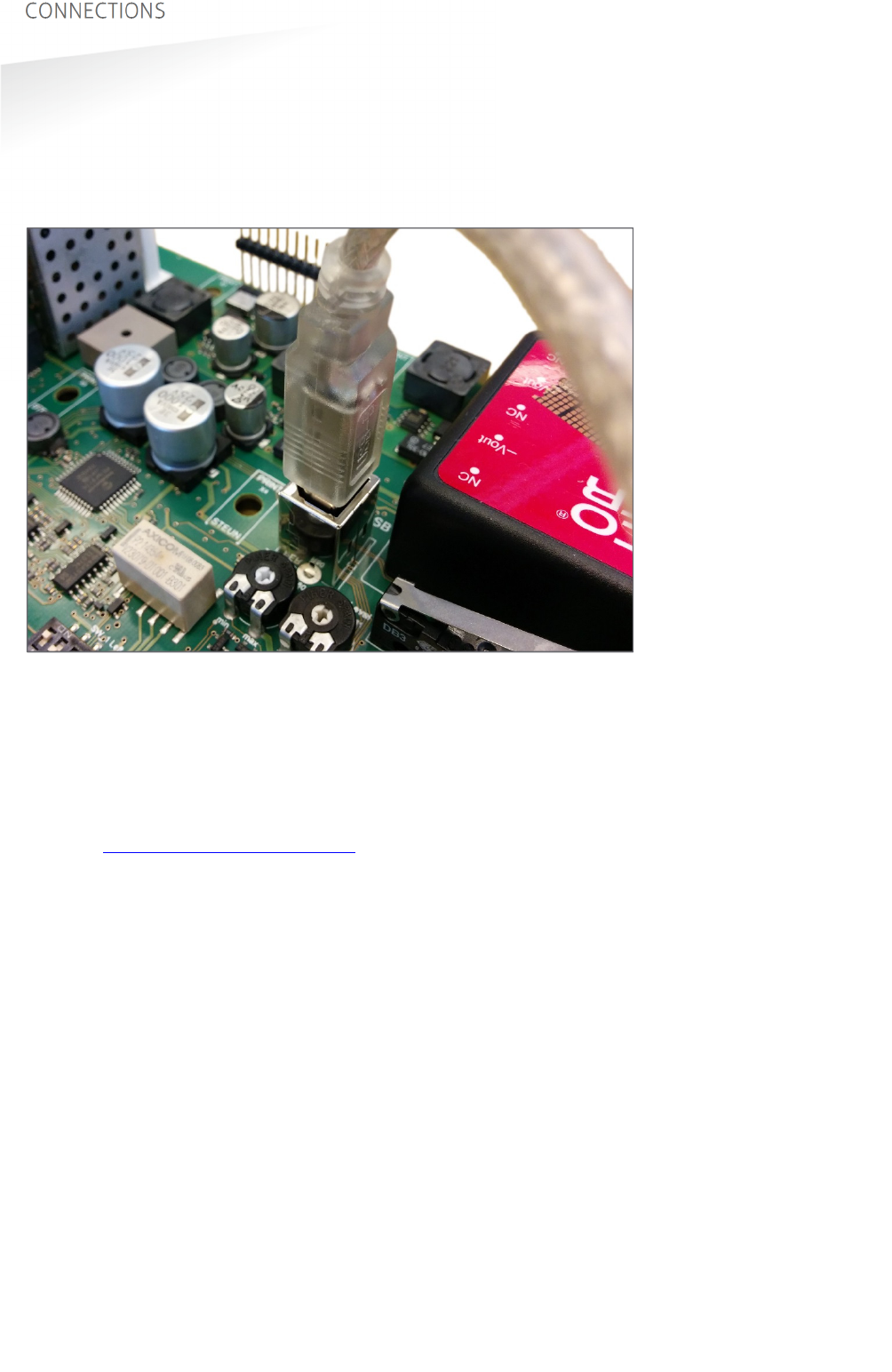
The TRANSIT Ultimate features an USB interface for service and installation
purposes. The USB connector (Type B) is accessible behind the cover. While the USB
interface is in use, the optional communication interface board is disabled.
Figure 11: USB connection
USB Virtual Com Port driver installation
Make sure your computer is connected to the internet. The driver usually is installed
automatically via Windows update when the USB interface is connected to your PC.
Follow the driver installation wizard. If you do not see the Windows update pop-up,
you can manually install the driver. To manually install, you need to go to FTDI’s
website at www.ftdichip.com/Drivers/VCP.htm and download the VCP (Virtual Com
Port) drivers for your operating system. Drivers for MacOS and Linux are available as
well.
TRANSIT ULTIMATE | INSTALLATION GUIDE
CONNECTIONS
16/36
3.3.2
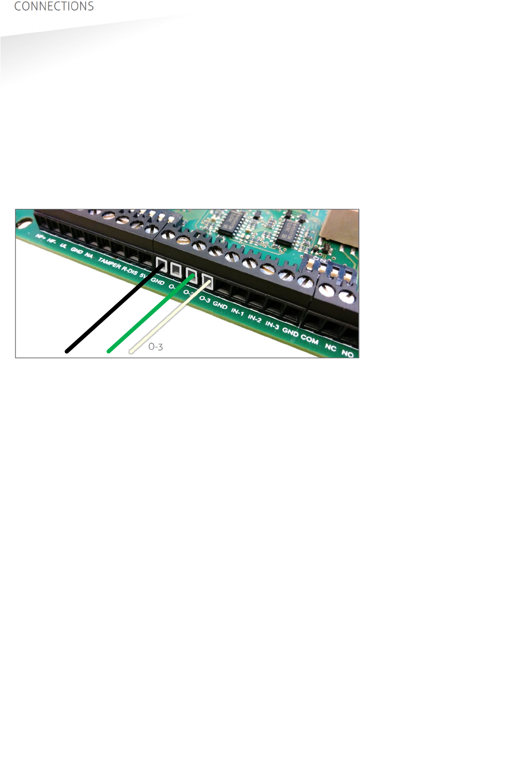
WIEGAND / MAGSTRIPE / BARCODE
The synchronous communication interface wiring uses the connections described
below. The actual protocol output depends upon the reader firmware. Please refer to
the firmware manual for more details.
Connections Wiegand Magstripe Barcode
O-1
- Card Loaded -
O-2
Data-0 (green) Clock -
O-3
Data-1 (white) Data Data
GND
Ground (black) Ground Ground
The picture below illustrates the Wiegand wiring.
Figure 12: Wiegand wiring
Cable specification:
4 x 0.25mm
2
shielded
Maximum cable length: 150 meter.
GND O-2 O-3
TRANSIT ULTIMATE | INSTALLATION GUIDE
CONNECTIONS
17/36
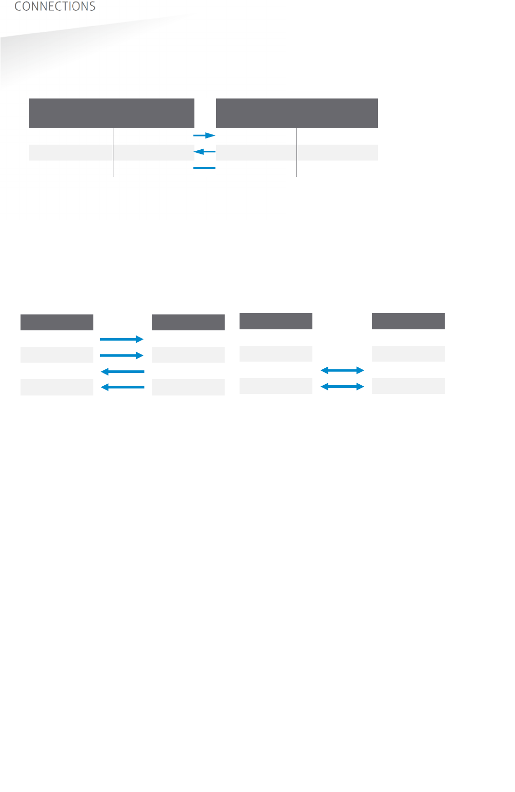
3.3.3
RS232 COMMUNICATION
TRANSIT SIDE
DIN 25 Name
PC SIDE
DIN 9 Name
2 TXD
2 RXD
3 RXD 3 TXD
7 GND
5 GND
Cable specification:
3 x 0.25mm
2
shielded
Maximum cable length: 30 meter.
3.3.4
RS422 COMMUNICATION
RS422 RS485
Jumper in position RS422. Jumper in position RS485.
CM422/485 RS422 HOST
TX+ RX+
TX- RX-
RX+ TX+
RX- TX-
Cable specification:
2 x 2 x 0.25mm
2
twisted pair shielded
Maximum cable length: 30 meter.
CM422/485 RS485 HOST
TX+ -
TX- -
RX+ A (-)
RX- B (+)
TRANSIT ULTIMATE | INSTALLATION GUIDE
CONNECTIONS
18/36
3.4
DIGITAL I/O
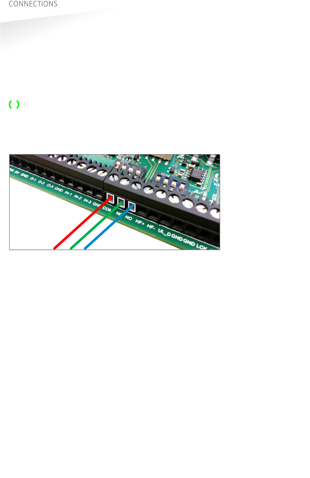
3.4.1
RELAY OUTPUT
The relay output is automatically activated upon successful identification /
authentication of a transponder. The automatic-relay-activation-mode can be
configured using the firmware. Please refer to the firmware manual for more details.
Authentication is only performed when Ultimate-mode is enabled. See chapter 4.3
for more details.
The front cover LED lights-up simultaneously with the relay output.
Connections:
NO
Relay contact normally open
NC
Relay contact normally closed
COM
Relay contact common
Figure 13: Relay output connections
Contact ratings:
Max. switching current: 2A
Max. switching voltage: 24VDC
Max. switching power: 50W
COM NC NO
TRANSIT ULTIMATE | INSTALLATION GUIDE
CONNECTIONS
19/36
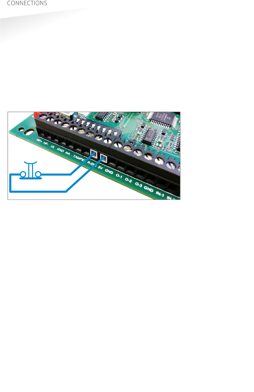
3.4.2
READ DISABLE INPUT
The reading of the TRANSIT Ultimate can be completely disabled with the read
disable input (RDIS). This input is commonly used in combination with a sensor (e.g.
inductive loop) that detects the presence of a person or vehicle. Use always a relay
contact to connect the internal 5V to the RDIS input. When the RDIS input is unused,
reading is enabled.
Connections:
R-DIS
Read disable input
5V
Internal 5V source for read disable input.
Warning: using an external 5V supply could damage the reader.
Figure 14: Read disable input
R-DIS
5V
TRANSIT ULTIMATE | INSTALLATION GUIDE
CONNECTIONS
20/36
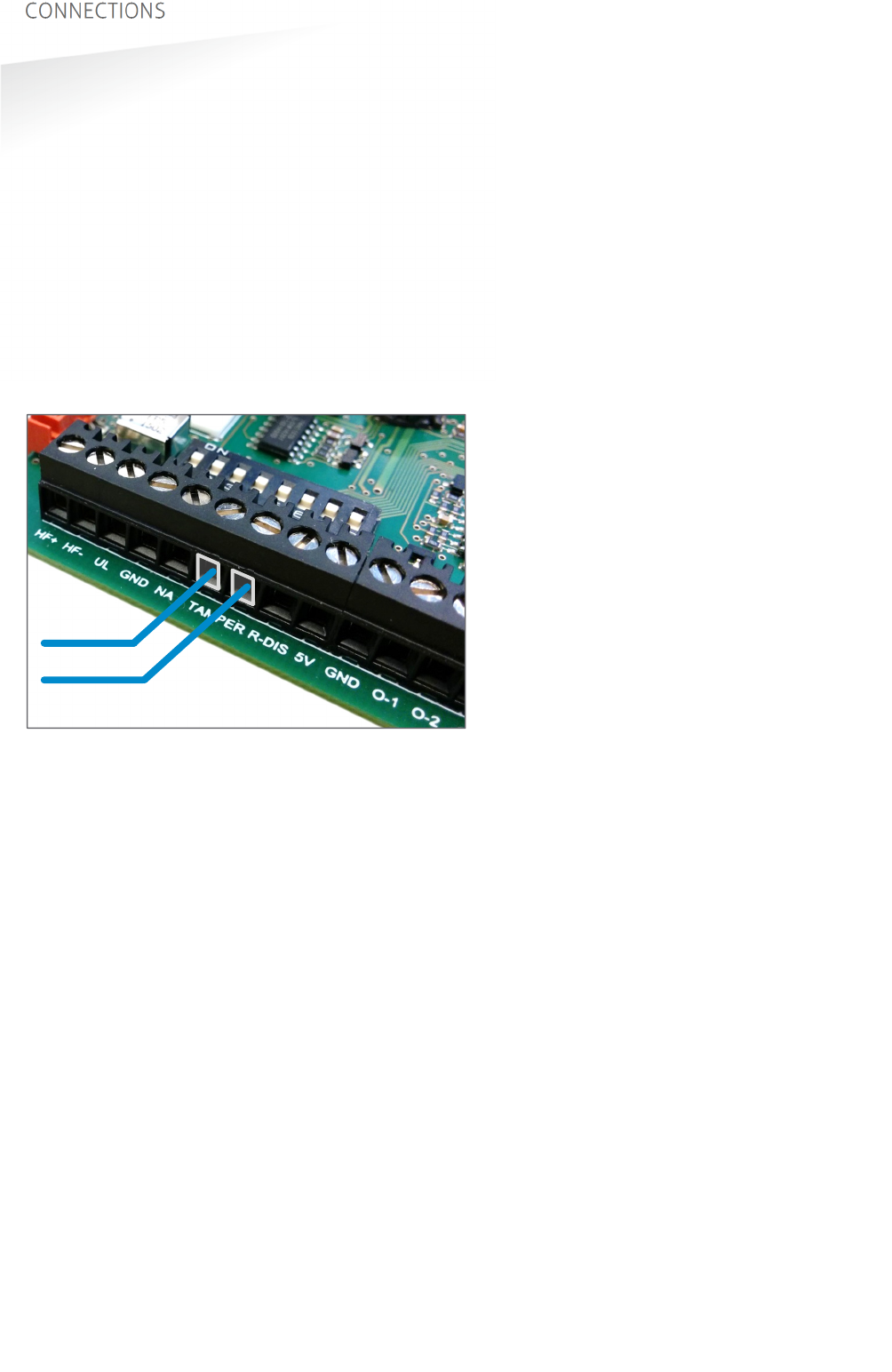
3.4.3
TAMPER SWITCH
The TRANSIT Ultimate features an internal tamper switch that indicates when the
cover is opened. This contact may be connected to an external alarm system. The
contacts are normally closed when the cover is in place.
Tamper switches of multiple TRANSIT Ultimate readers may be connected in series.
Connections:
TAMPER
Tamper switch contacts (normally closed)
TAMPER
“
Contact ratings:
Max. switching current: 50 mA (0.5V voltage drop)
Max. switching voltage: 24 VDC
Figure 15: Tamper switch
TAMPER
TRANSIT ULTIMATE | INSTALLATION GUIDE
CONNECTIONS
21/36
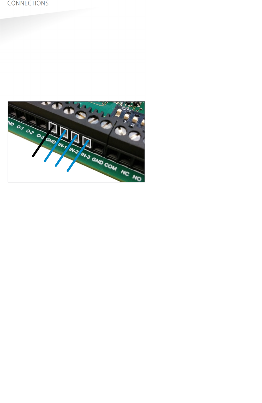
3.4.4
GENERAL PURPOSE INPUTS
Three general purpose inputs are available on the TRANSIT Ultimate. The inputs are
active low. No external voltage should be applied to the inputs. Connect to ground
to activate or otherwise leave unconnected.
Connections:
IN-1
General purpose input 1
IN-2
General purpose input 2
IN-3
General purpose input 3
GND
Ground
Figure 16: GPIO inputs
GND
IN-1 IN-2
IN-3
TRANSIT ULTIMATE | INSTALLATION GUIDE
CONNECTIONS
22/36
3.5
SPECIAL CONNECTIONS
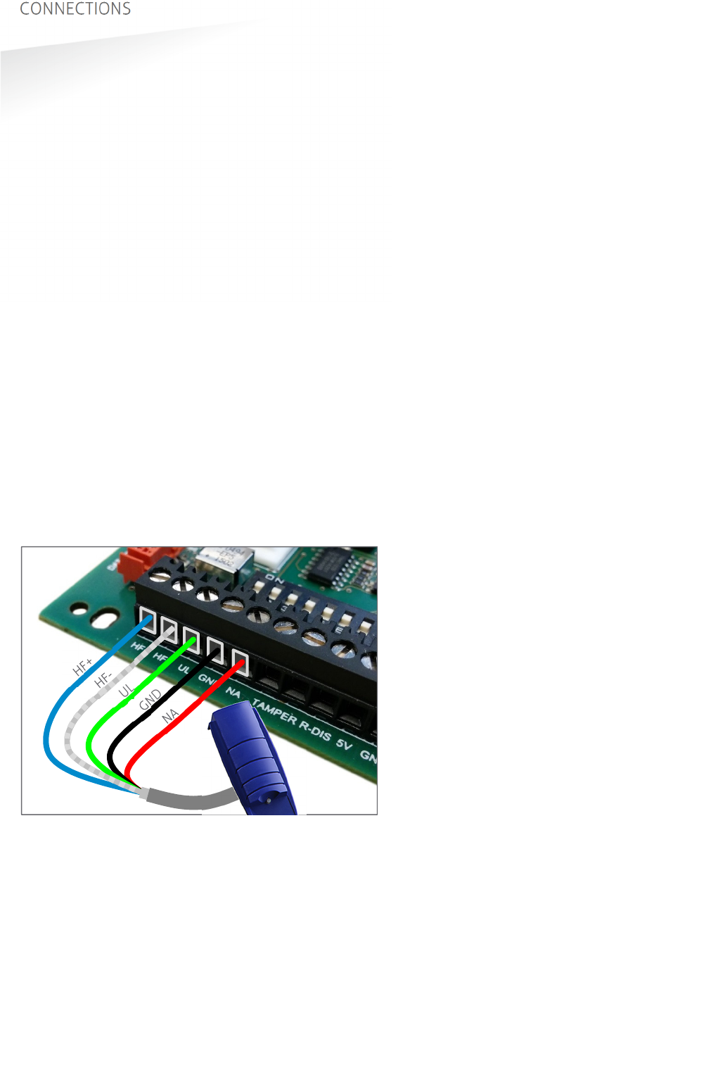
3.5.1
PROXIMITY ANTENNA
Optionally a NEDAP proximity antenna can be connected to the TRANSIT Ultimate to
enable simultaneously long-range and proximity identification. This is useful when
controlling a gate where vehicles as well as pedestrians, cyclists and/or motorists
can enter.
The antenna can be either a NEDAP low-frequency proximity antenna or a NEDAP
reader with RF output, such as an uPASS Access, ConveXS or another TRANSIT reader.
The green-, and red-LED output connections UL and NA are suitable to directly drive
external LEDs with max. 18mA. Note that this is not compatible with the active-low
reader inputs on the uPASS Access or ConveXS.
Connections:
HF+
Antenna+
HF-
Antenna- (cable shield)
UL
Green LED output (max. 18mA)
GND
Ground for LEDs
NA
Red LED output (max. 18 mA)
Cable specification:
4 x 0.25mm
2
shielded
Maximum cable length: 15 meter
Figure 17: Proximity antenna connections
Notes:
- While using the proximity antenna no authentication or other Ultimate functions
are performed.
- DIP switch 8 must be in the OFF position to enable this function.
TRANSIT ULTIMATE | INSTALLATION GUIDE
CONNECTIONS
23/36
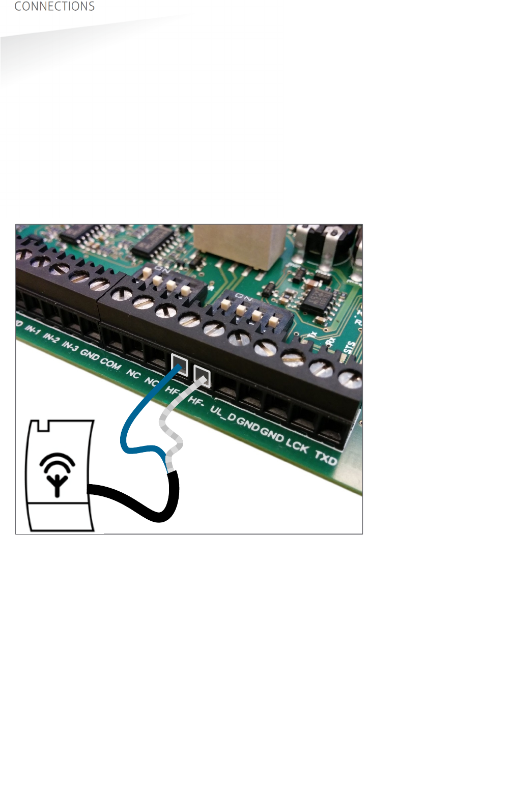
3.5.2
NEDAP ANTENNA MODULATION
The Nedap antenna modulation interface is used to connect the TRANSIT Ultimate to
NEDAP AEOS access control hardware such as the AP1001. Instead of a proximity
antenna the TRANSIT Ultimate can be connected.
Connections:
HF+
Antenna modulation output, connect to ANT
HF-
Antenna modulation ground (cable shield), connect to ANT GND.
Cable specification:
Coax RG58U
Maximum cable length: 100 meter
Figure 18: Antenna modulation connections
HF+
HF-
(cable shield)
NEDAP
AEOS
AP1001
TRANSIT ULTIMATE | INSTALLATION GUIDE
CONFIGURATION
24/36
4. CONFIGURATION
4.1
FIRMWARE OPTIONS
The TRANSIT Ultimate supports the same firmware versions as the TRANSIT Standard.
Different firmware versions are available to support different features and
communication protocols. For each firmware version a separate installation guide is
available.
Switches SW1-1 to SW1-8 are used to select various options within the actual
loaded firmware. They can be used for example to select the serial baud rate,
wiegand output options, etc. Refer to the specific firmware manual for details.
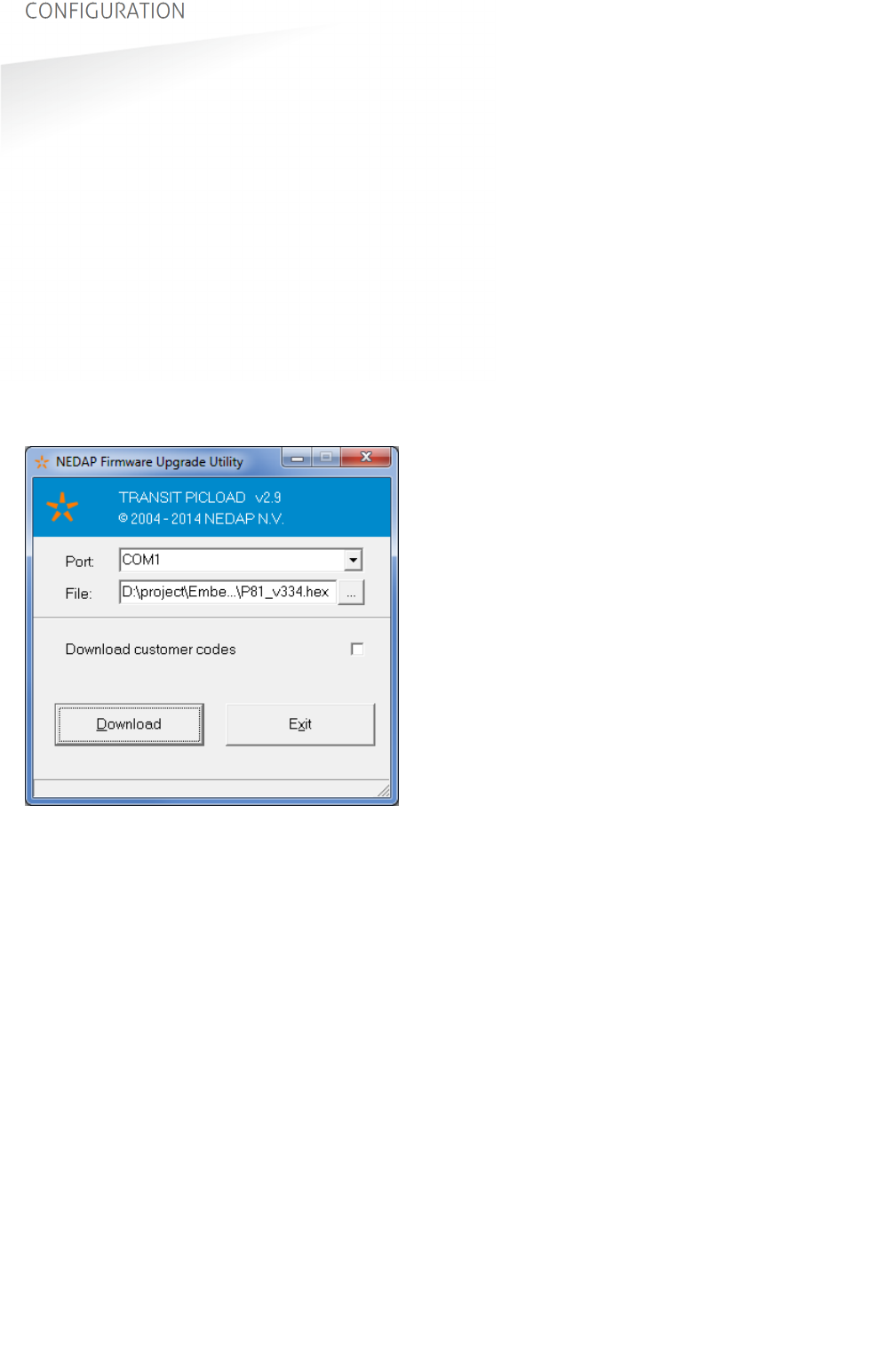
The firmware can be changed or updated using the TRANSIT Firmware Upgrade
software tool. Make sure that the serial communication select switch is set to
TRANSIT (PIC). See chapter 4.2.
Figure 19: TRANSIT Firmware Upgrade Utility
4.2
SERIAL COMMUNICATION SELECT
By default the USB or communication interface board connections will allow
communication with the TRANSIT processor (PIC). The communication protocol is
determined by the TRANSIT firmware. See also chapter 4.1 above.
The USB or communication interface board connections can also be used to
communicate with the processor located on the TAB board. This is for test purposes
and will not further be explained in this manual.
ON
1 2 3 4
SW2
ON
1 2 3 4
SW3
TRANSIT communication (PIC)
ON
1 2 3 4
SW2
ON
1 2 3 4
SW3
Test communication (TAB)
While the USB cable is connected, the communication interface board is disabled.
Note
If the message “Searching
for bootloader …” does not
disappear, then press the
reset-switch.

TRANSIT ULTIMATE | INSTALLATION GUIDE
CONFIGURATION
25/36
4.3
ULTIMATE-MODE
The TRANSIT Ultimate can operate in the ULTIMATE-mode or in the NORMAL-mode.
In the NORMAL-mode the TAB board is bypassed. The reader is compatible with the
TRANSIT Standard. In this mode the TRANSIT Ultimate can read original tags, such as
Compact-Tag, Window-Button, Heavy-Duty-Tag and Boosters. Also the Ultimate-tags
will work, but no authentication or other Ultimate functions are performed.
The ULTIMATE-mode only works in combination with Ultimate-tags.
ON
1 2 3 4
SW2
ON
1 2 3 4
SW3
ULTIMATE-mode
ON
1 2 3 4
SW2
ON
1 2 3 4
SW3
NORMAL-mode (TAB bypass)
4.4
RANGE BEEPER
Enable or disable the internal range beeper. The beeper indicates transponder
identification. The signal strength of the identified transponder determines the
beeping frequency. When the transponder is near to the reader the range beeper
will beep fast.
ON
1 2 3 4
SW2
ON
1 2 3 4
SW3
Range beeper ON
ON
1 2 3 4
SW2
ON
1 2 3 4
SW3
Range beeper OFF
TRANSIT ULTIMATE | INSTALLATION GUIDE
CONFIGURATION
26/36
4.5
FREQUENCY SELECTION
The TRANSIT Ultimate reader operates in the 2.45GHz ISM frequency band.
When two or more readers are within a range of 15 meters (50 feet), these readers
should be set on a different operating frequency.
It may also be required to select a different frequency to avoid disturbance between
the TRANSIT Ultimate and other 2.45GHz equipment, such as Wi-Fi access points.
Please also read chapter 4.7 when experiencing interference.
The frequency channel is selected on the transceiver board which is located in the
front cover of the reader. Select the frequency channel using a display & push-
buttons (see chapter 4.5.1) or using dip-switches (see chapter 4.5.2).
Note: the TAB board uses 2 frequency channels in the 433 MHz band, which cannot
be changed.
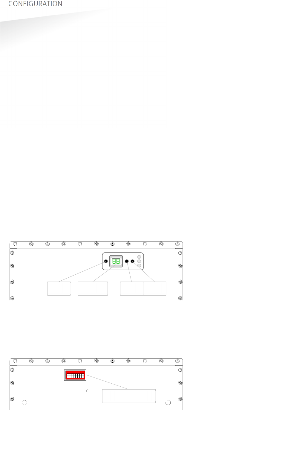
4.5.1
FREQUENCY SELECT DISPLAY & BUTTONS
Only for TRANSIT Ultimate FCC ID: CGDTRANSITULT2 (IC: 1444A-TRANSITULT2)
Press the RST button to activate the display. The display will show the value
indicating the currently selected frequency. Lookup the display value in appendix B.
Press UP to select a higher frequency. Press DOWN to select a lower frequency.
The display will automatically switch off after 60 seconds
4.5.2
FREQUENCY SELECT DIP-SWITCHES
Only for TRANSIT Ultimate FCC ID: CGDTRANSITULTI (IC: 1444A-TRANSITULTI)
Select a frequency channel using the dip-switches located on the transceiver board
in the front cover of the reader. Refer to frequency selection table appendix B.
DOWN UP RST
DISPLAY
12345678
DIP-SWITCHES
TRANSIT ULTIMATE | INSTALLATION GUIDE
CONFIGURATION
27/36
4.6
READ RANGE CONTROL
The read range of the TRANSIT Ultimate can be controlled with the embedded
squelch function. The squelch references the received signal strength against the
squelch level setting. When the received signal strength is below the squelch level
no identification is possible. The received signal strength becomes higher when the
transponder comes closer to the reader. When the received signal strength exceeds
the squelch level the transponder will be identified.
Distance
Received signal strength
0 m 5 m
max read range
for this level
squelch level setting
Tag signal < squelch level: no read
Tag signal > squelch level: read
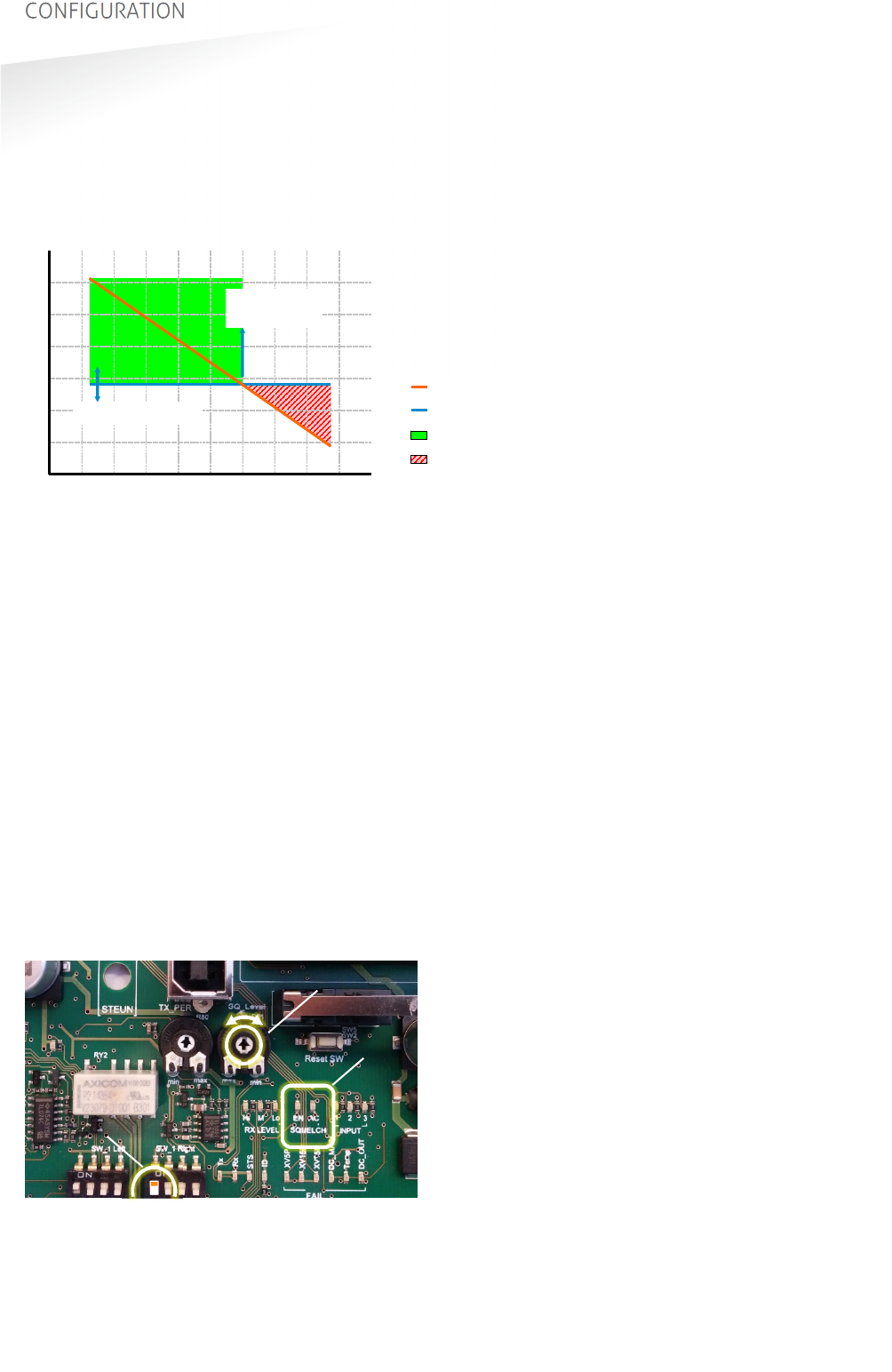
Squelch level
Tag signal
Figure 20: Squelch principle
Adjustment of the read range is done by enabling the squelch and setting the
squelch level with its potentiometer. To achieve the maximum read range, disable
the squelch function completely with the enable/disable squelch switch.
Two LEDs indicate the status of the squelch. When the squelch is enabled LED SQ-
ENA will be on. LED SQ-ACT is on when the transponder signal is below the squelch
level (red area in Figure 20). In chapter 5 all LED indicators are described.
ON
1 2 3 4
SW2
ON
1 2 3 4
SW3
Squelch enabled
ON
1 2 3 4
SW2
ON
1 2 3 4
SW3
Squelch disabled (max. read range)
SQ-Level potentiometer completely clockwise:
Maximum read range.
SQ-Level potentiometer completely counter-clockwise:
Minimum read range.
Figure 21: Squelch controls
leds
potentiometer
dip-switch
TRANSIT ULTIMATE | INSTALLATION GUIDE
CONFIGURATION
28/36
4.7
MICROWAVE TIME-SHARING
The microwave antenna of the TRANSIT Ultimate is continuously on. This will ensure
the fastest identification times. However it may cause interference on other 2.45GHz
equipment.
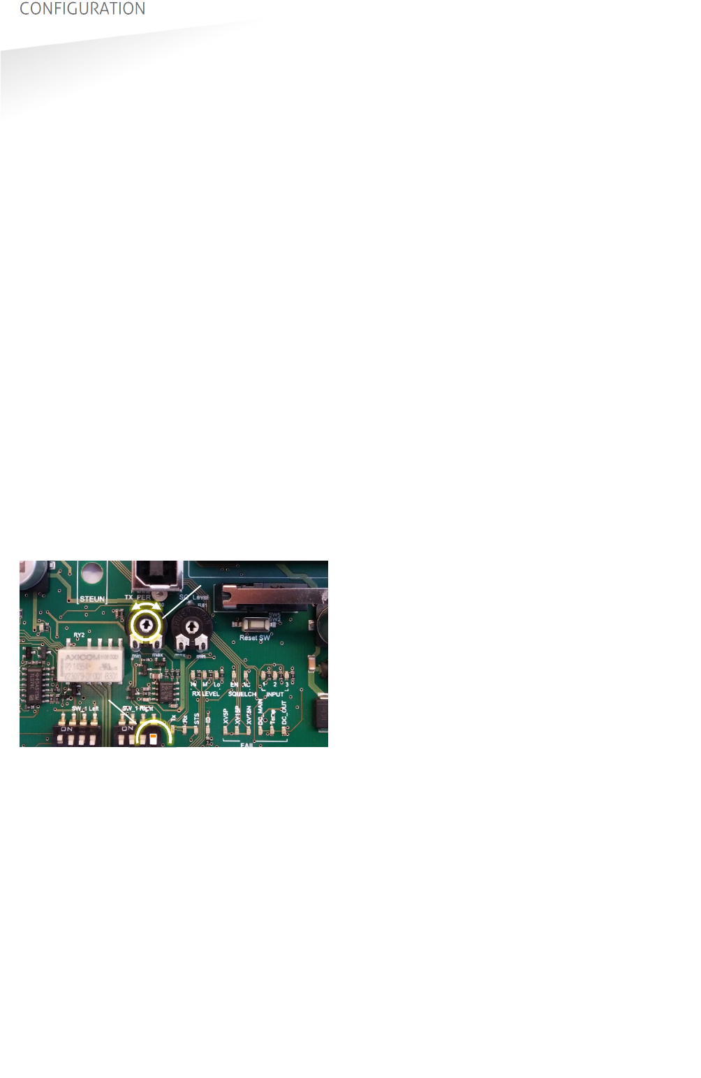
Enable the microwave time-share mode to only use the selected frequency
periodically (the reader automatically switches on and off). During the periods that
the TRANSIT reader is off, other equipment can use the same frequency undisturbed.
The reader will be on for 300 milliseconds, which is long enough for a reliable
identification of a tag. The off-time is between 0.5 and 5 seconds. This is
configurable with the TX-PER potentiometer.
ON
1 2 3 4
SW2
ON
1 2 3 4
SW3
Microwave continuously-on
ON
1 2 3 4
SW2
ON
1 2 3 4
SW3
Microwave time-share (periodically on)
TX-PER potentiometer completely counter-clockwise:
Short off (500 msec).
TX-PER potentiometer completely clockwise:
Long off (5000 msec).
To avoid disturbance or interference you can also try to select an unused frequency
channel as described in chapter 4.5.
Figure 22: Microwave time-sharing controls
potentiometer
dip-switch
TRANSIT ULTIMATE | INSTALLATION GUIDE
LED INDICATIONS
29/36
5. LED INDICATIONS
5.1
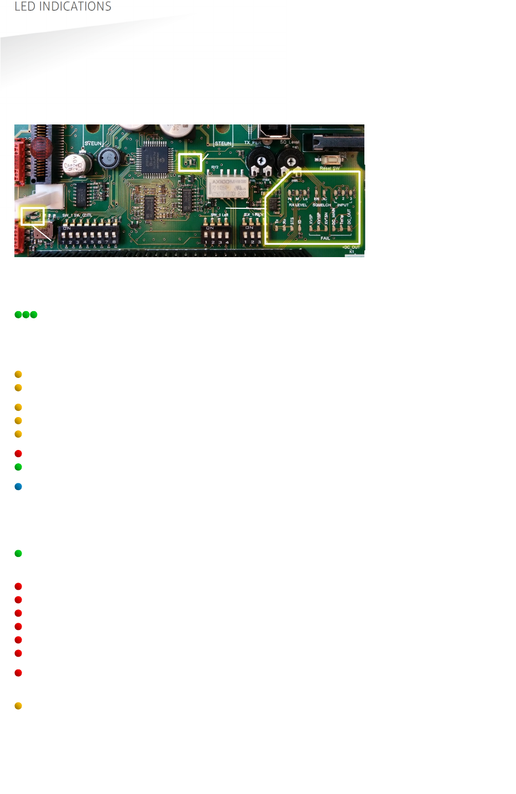
MAIN BOARD INDICATIONS
A number of LEDs on the main board of the TRANSIT Ultimate indicate the status of
the reader. The list below describes the function of each LED.
Figure 23: LED indications main board
Led Description
RX_LEVEL LED bar indicating the received microwave tag signal strength. This
LED bar may also indicate the presence of radio interference. In
case of interference, try switching to a different frequency. See
chapter 4.5.
SQ-EN Squelch enabled. See chapter 4.6.
SQ-ACT Squelch active. See chapter 4.6.
INPUT-1 Input 1 status. On when contact is closed. See chapter 3.4.4.
INPUT-2 Input 2 status. On when contact is closed.
INPUT-3 Input 3 status. On when contact is closed.
Tx Transmit serial data (USB, I/F-board). See chapter 4.2.
Rx Receive serial data (USB, I/F-board).
STS-LED TRANSIT firmware status LED (PIC)
Slow blinking: Heartbeat (0.8s on / 0.8s off)
Fast blinking: Boot loader active. Indicated after restart.
Twice blinking: Configuration menu active.
Off: Abnormal situation.
ID-LED TRANSIT identification. Blinks fast upon valid tag.
When no identification check dip-switches and customer-code.
FAIL-XV5P Power supply failure +5V.
FAIL-XV15P Power supply failure +15V.
FAIL-XV15N Power supply failure -15V.
FAIL-DC_MAIN Power supply failure DC-MAIN.
FAIL-Temp Temperature critically high.
FAIL-DC_OUT DC OUTPUT overload. See chapter 3.2.3.
Unlocked PLL unlocked. Check flat cables to transceiver board. Try switching
to a different frequency. See chapter 4.5.
Read disable Read Disable LED. On while reading disabled. See chapter 3.4.2.
Unlocked
Read disable
LEDs
TRANSIT ULTIMATE | INSTALLATION GUIDE
LED INDICATIONS
30/36
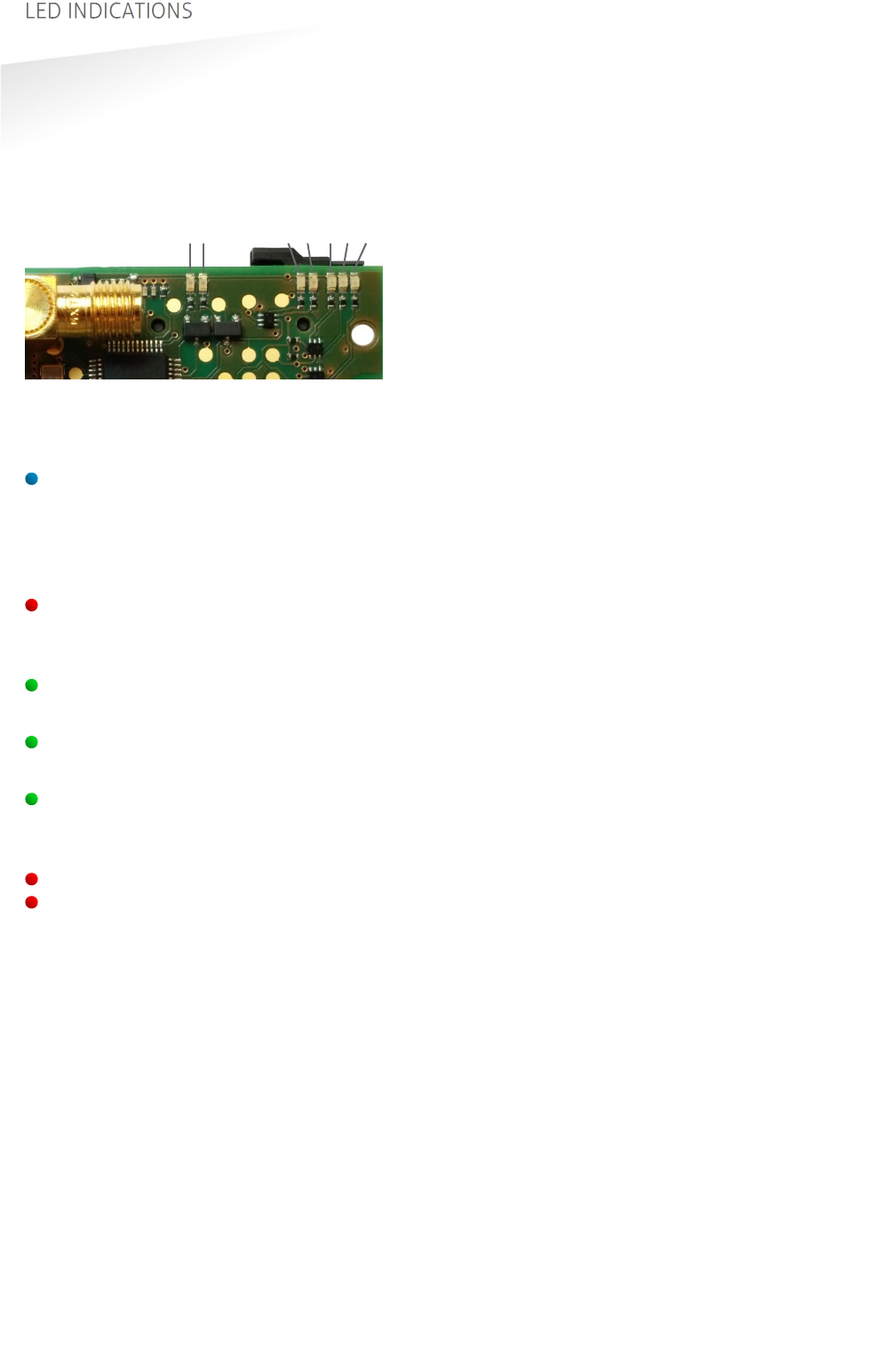
5.2
TAB BOARD INDICATIONS
The LEDs on the TAB board indicate its status. These LEDs are very useful when
troubleshooting the Ultimate-mode features. Below the function of each LED is
described.
Figure 24: LED indications TAB board
Led Description
STS TAB board status LED
Fast blinking: Boot loader active. Indicated after restart.
Regular blinking: Heartbeat (0.5s on / 0.5s off)
Special blink 1: Programmer firmware (0.1s on / 0.9s off).
Special blink 9: TAB stopped. Hardware fault, (0.9s on / 0.1s off).
ERR Error LED.
SAM error – not present, not locked, not supported, etc.
TAB error – authentication failed.
2.45 2.45GHz microwave tag data received.
Does not indicate when TAB bypassed. See chapter 4.3.
433 433MHz tag data received.
Only indicated when using Ultimate tags.
GOOD Ultimate tag successfully authenticated.
Tag data transmitted to TRANSIT Ultimate main board.
TRANSIT should be able to identify now. Check ID-LED main board.
Tx Transmit serial data (USB, I/F-board). See chapter 4.2.
Rx Receive serial data (USB, I/F-board).
Tx
Rx
STS
ERR
2.45
433
GOOD

TRANSIT ULTIMATE | INSTALLATION GUIDE
Technical Specifications
31/36
A TECHNICAL SPECIFICATIONS
Technical specification TRANSIT Ultimate
Power supply 100 – 240 VAC (60 – 50 Hz) or 24 VDC (± 10%)
Power consumption < 25 VA (AC), < 20 W (DC)
Power output 24Vdc, 0.1A
Dimensions 330 x 274 x 140 mm
Weight 5 kg
Housing Cover: ABS, Housing: Die-cast ADC12
Protection IP66, outdoor use
Operating temperature -30°C – +60°C
Maintenance Transit Ultimate is free of regular maintenance
Detection range Up to 10 meters, message acceptance ratio > 80%
Object speed Up to 200 km/h at appropriate distance (*)
Operating frequency 2.438 – 2.457 GHz, 433.62 & 434.22 MHz (RX_CAT_3); Ton < 5 sec
Frequency channels 2.45GHz 48 FCC channels, 14 ETSI channels, 600k Hz spacing
Polarization 2.45 GHz Circular (LHC)
Polarization 433 GHz Horizontal
Air interface 2.45 GHz Nedap proprietary encryption standard
1.875 kbps; integrated antenna
Air interface 433 MHz Encryption based upon diversified AES128 keys.
300 kbps; GFSK - 75kHz; dedicated antenna
Duty cycle < 1%; LBT not applicable
Relay output 1 relay output (NO, common, NC), 24 VDC 2A
Inputs 3 dry contact
Audio Range check beeper
Antenna input External inductive proximity antenna connection 120kHz
Antenna output Nedap external reader antenna connection 120kHz output
Interfaces USB, Wiegand, Magstripe, Barcode (*).
Optional interface boards: RS232, RS422, RS485 (*), TCP/IP (*), Profibus-DP (*).
Communication protocols Determined by firmware: CR/LF, DC2/DC4, various OEM protocols, several
Wiegand and Magstripe formats.
Mounting Wall Mounting Set included, optional Pole Mounting Kit available.
Certifications:
EMC EMC Directive EC : 2014/30/EC ; 2004/108/EC
EN301 489-1,-3,-17 ; EN61000-6-2 ; EN61000-6-3
Regulations FCC part 15.245; EN 300 440 (2.45 GHz)
FCC part 15.231a,-b ; EN 300 220 (433 MHz)
UL294 6th ed. Access Control Performance Line security: Level 1
Destructive attack: Level 1
Endurance: Level 4
Standby Power: Level 1
This Transit Ultimate reader must be connected and controlled by a UL listed
controller (e.g. AP4803X).
(*) not evaluated by UL

TRANSIT ULTIMATE | INSTALLATION GUIDE
Frequency Channels
32/36
B FREQUENCY CHANNELS
Transceiver board frequency channel selection table:
Display value Frequency (GHz) SW1 SW2 SW3 SW4 SW5 Wi-Fi ETSI FCC
4C 2.4360 - - - - - -
4D 2.4366 - - - - - -
4E 2.4372 - - - - - CH6 -
4F 2.4378 - - - - - -
50 2.4384 ON ON ON ON ON -
51 2.4390 OFF ON ON ON ON -
52 2.4396 ON OFF ON ON ON -
53 2.4402 OFF OFF ON ON ON -
54 2.4408 ON ON OFF ON ON -
55 2.4414 OFF ON OFF ON ON -
56 2.4420 ON OFF OFF ON ON CH7 -
57 2.4426 OFF OFF OFF ON ON -
58 2.4432 ON ON ON OFF ON -
59 2.4438 OFF ON ON OFF ON -
5A 2.4444 ON OFF ON OFF ON -
5B 2.4450 OFF OFF ON OFF ON -
5C 2.4456 ON ON OFF OFF ON -
5D 2.4462 OFF ON OFF OFF ON
5E 2.4468 ON OFF OFF OFF ON
5F 2.4474 OFF OFF OFF OFF ON CH8
60 2.4480 ON ON ON ON OFF
61 2.4486 OFF ON ON ON OFF
62 2.4492 ON OFF ON ON OFF
63 2.4498 OFF OFF ON ON OFF
64 2.4504 ON ON OFF ON OFF
65 2.4510 OFF ON OFF ON OFF
66 2.4516 ON OFF OFF ON OFF
67 2.4522 OFF OFF OFF ON OFF CH9
68 2.4528 ON ON ON OFF OFF
69 2.4534 OFF ON ON OFF OFF
6A 2.4540 ON OFF ON OFF OFF -
6B 2.4546 OFF OFF ON OFF OFF -
6C 2.4552 ON ON OFF OFF OFF -
6D 2.4558 OFF ON OFF OFF OFF -
6E 2.4564 ON OFF OFF OFF OFF -
6F 2.4570 OFF OFF OFF OFF OFF CH10 -
70 2.4576 - - - - - -
71 2.4582 - - - - - -
72 2.4588 - - - - - -
73 2.4594 - - - - - -
74 2.4600 - - - - - -
75 2.4606 - - - - - -
76 2.4612 - - - - - -
77 2.4618 - - - - - CH11 -
78 2.4624 - - - - - -
79 2.4630 - - - - - -
7A 2.4636 - - - - - -
7B 2.4642 - - - - - -
The selected frequency has to comply with local radio regulations.
ETSI frequency range from 2.446 to 2.454 GHz.
FCC frequency range from 2.435 to 2.465 GHz.

TRANSIT ULTIMATE | INSTALLATION GUIDE
Nedap Part Numbers
33/36
C NEDAP PART NUMBERS
Product Part number Description
9215689 TRANSIT Ultimate
9216537 Security Key Pack (SAM)
5626595 Pole Mounting Kit
9218327 Weather Protection Hood
7819102 HID Interface Board (HIB)
7817940 TCP/IP Interface Board (*)
7817347 RS422/RS485 Interface Board
7806434 RS232 Interface Board
7817134 Profibus DP Interface Board (*)
9564314 Window Tag Ultimate
9982809 Smartcard Booster Ultimate
9982817 LEGIC Booster Ultimate (*)
(*) not evaluated by UL

TRANSIT ULTIMATE | INSTALLATION GUIDE
FCC / IC Statement
34/36
D FCC / IC STATEMENT
FCC ID: CGDTRANSITULT2
IC: 1444A-TRANSITULT2
FCC ID: CGDTRANSITULTI
IC: 1444A-TRANSITULTI
Compliance statements (part15.19)
This device complies with part 15 of the FCC Rules and to RSS210 of Industry Canada. Operation is subject to the
following two conditions:
(1) this device may not cause harmful interference, and
(2) this device must accept any interference received, including interference that may cause undesired operation.
Cet appareil se conforme aux normes CNR210 exemptés de licence du Industry Canada.
L'opération est soumise aux deux conditions suivantes:
(1) cet appareil ne doit causer aucune interférence, et
(2) cet appareil doit accepter n'importe quelle interférence, y inclus interférence qui peut causer une opération
non pas voulu de cet appareil.
Warning (part15.21)
Changes or modifications not expressly approved by party responsible for compliance could void the user’s
authority to operate the equipment. This in particular is applicable for the antenna which can be delivered with the
TRANSIT ULTIMATE System.
RF Exposure (OET Bulletin 65)
To comply with FCC RF exposure requirements for mobile transmitting devices, this transmitter should only be
used or installed at locations where there is at least 20cm separation distance between the antenna and all
persons.
Information to the User (Part 15.106(b))
Note: This equipment has been tested and found to comply with the limits for a class B digital devices, pursuant to
part 15 of the FCC Rules. These limits are designed to provide reasonable protection against harmful interference
in a residential installation. This equipment generates, uses and can radiate radio frequent energy and, if not
installed and used in accordance with the instructions, may cause harmful interference to radio communications.
However, there is no guarantee that interference will not occur in a particular installation. If this equipment does
not cause harmful interference to radio or television reception, which can be determine by turning the equipment
off and on, the user is encouraged to try to correct the interference by one or more of the following measures:
- Reorient or relocate the receiving antenna.
- Increase the separation between the equipment and receiver.
- Connect the equipment into an outlet on a circuit different from that to which the receiver is connected.
- Consult the dealer or an experienced radio/TV technician for help.

TRANSIT ULTIMATE | INSTALLATION GUIDE
Disclaimer
35/36
E DISCLAIMER
This information is furnished for guidance, and with no guarantee as to its accuracy or completeness; its
publication conveys no license under any patent or other right, nor does the publisher assume liability for any
consequence of its use; specifications and availability of goods mentioned in it are subject to change without
notice; it is not to be reproduced in any way, in whole or in part, without the written consent of the publisher.

TRANSIT ULTIMATE | INSTALLATION GUIDE
Document revision
36/36
F DOCUMENT REVISION
Version Date Comment
5.01 2017-08-17 HR: updates for changed transceiver board
4.10 2017-07-17 HR: added outdoor use statement
4.09 2016-10-06 HR: added time sharing chapter
4.08 2016-08-08 HR: weather protection hood added
4.07 2016-01-14 HR: wall mounting set updated
4.06 2015-12-17 HR: update for UL certification
4.05 2015-08-25 HR: update for compliance certification
4.04 2015-08-25 HR: mounting sets naming unambiguous
4.03 2015-07-22 HR: updated dip-switch
4.02 2015-06-09 HR: updated technical specifications
4.01 2015-06-01 HR: updated frequency channel table
4.00 2015-04-10 HR: Initial version