Nedap N V VELOS4 RFID Reader for Livestock User Manual manual
N. V. Nederlandsche Apparatenfabriek NEDAP RFID Reader for Livestock manual
manual
Service manual
For installation, operation and service
ISO Reader I/O
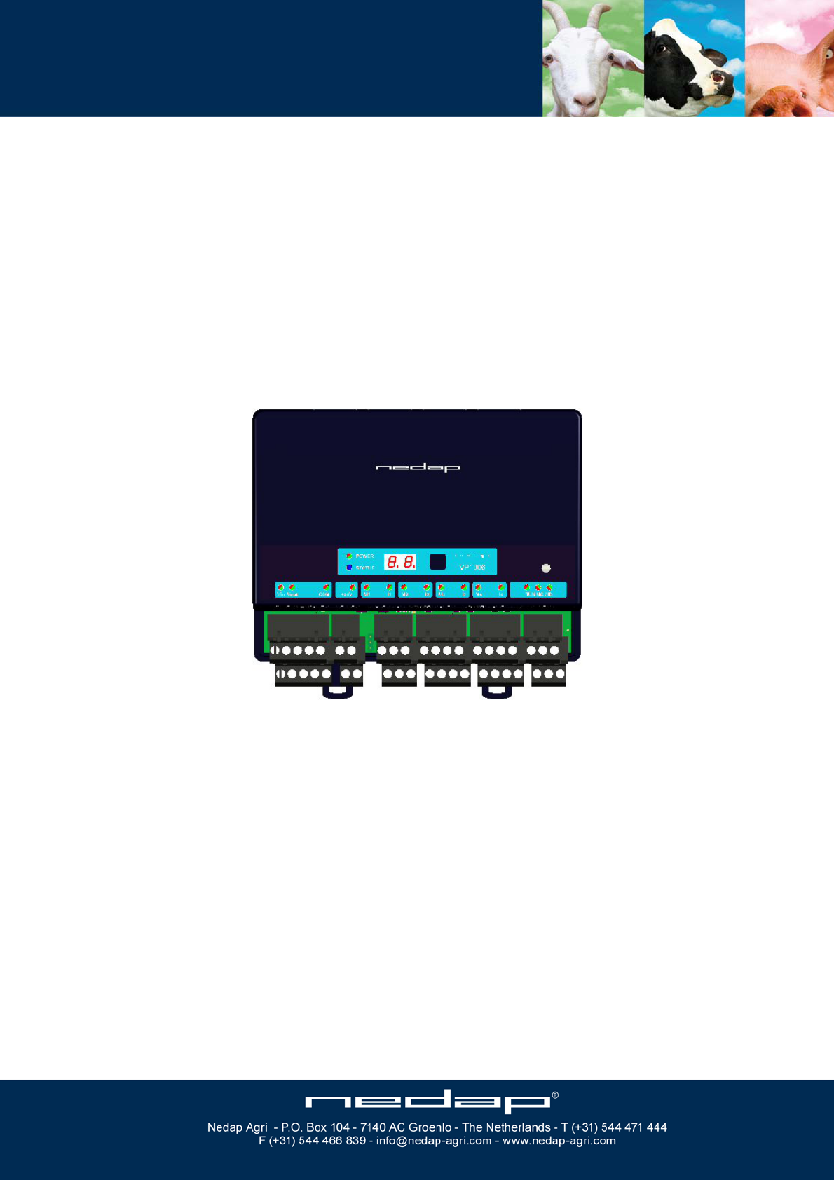
VP1007
April 2009 / Manual version 0.4

VP1007-200PM-00 ISO Reader I/O Manual version 0.4
Version overview
Manual version 0.4 / 4 - 2009
This information is furnished for guidance, and with no guarantee as to its accuracy or completeness; its publication conveys no
license under any patent or other right, nor does the publisher assume liability for any consequence of its use; specifications and
availability of goods mentioned in it are subject to change without notice; it is not to be reproduced in any way, in whole or in
part, without the written consent of the publisher.
© Nedap N.V., AGRI P.O. Box 104 NL-7140 AC GROENLO The Netherlands

VP1007-200PM-00 ISO Reader I/O Manual version 0.4
VP1007 ISO Reader I/O
Contents
1 Introduction 1
2 Description and functioning 2
3 Safety 3
4 Installation 3
4.1 Mounting 3
4.2 Connections 4
5 Adjustments 5
5.1 Check after power up 5
5.2 Address 5
5.3 Antenna 6
5.4 Software setup 6
6 Advanced 7
6.1 Testing inputs and outputs 7
6.2 Advanced antenna adjustment 7
6.3 Identification test options 8
7 Trouble shooting 9
8 Maintenance, cleaning and disposal 10
Appendix A: Specifications 11
Appendix B: Display and push button 12
Appendix C: Overview display menu 13
Appendix D: LED indicator overview 14
Appendix E: RS485 connection 15
Appendix F: RS232 connections 16

VP1007-200PM-00 ISO Reader I/O Manual version 0.4
VP1007-200PM-00 ISO Reader I/O Manual version 0.4 / Page 1
Preface
This manual is part of the service documentation for Nedap Velos. Reference is also made to other
manuals that are part of the Nedap Velos documentation. For an overview of available Nedap Velos
manuals see the manual “Nedap Velos General Description”, or visit the Nedap Agri website
www.nedap-agri.com.
1 Introduction
The Velos VP1007 is used for identification of animals for feeding, weighing, milking, heat detection
etc. The VP1007 must be connected to a computer (controller) and can communicate by a CAN,
RS485 or RS232 protocol. The connected computer must give controlling commands to the VP1007 to
operate inputs, outputs and identification.
The VP1007 has the following main tasks:
- Identification of tags (ISO 134.2 kHz FDX/HDX)
Two antenna connections available, 1 active at the time
- Controlling outputs
5 outputs are available to activate e.g. lights, motors, valves, relays
5 protected outputs for continues 25V, e.g. power for sensors
- Reading inputs
5 inputs available for e.g. sensors, switches
- Communication
RS232 or RS485 to connect e.g. a weigh computer
Following antenna types can be used: V-sense antennas
The VP1007 must be installed in a housing suitable for farm conditions, for example in a V-box.
Reference manuals : PS0000-200PM-00 Velos general description
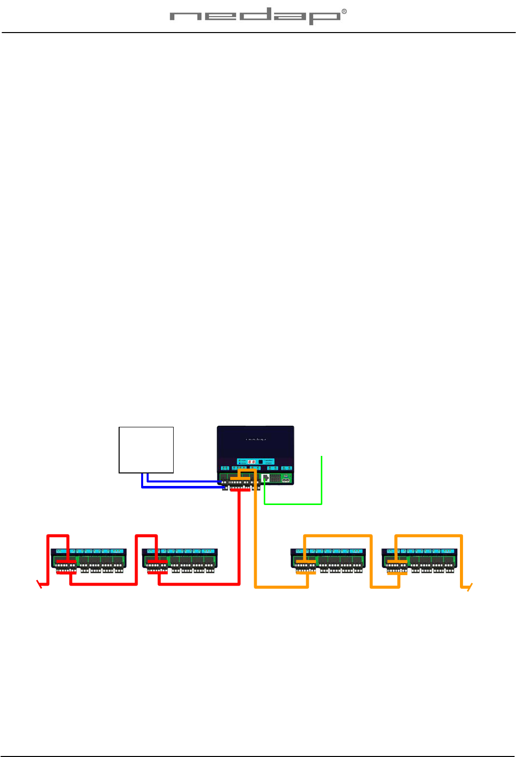
VP1007 VP1007
VP1007 VP1007
VPU To PC (LAN ethernet)
CAN-bus channel 1
CAN-bus channel 2
Power
Supply
max 3m
Max number of V-packs and cable length depends on configuration used
VP1007-200PM-00 ISO Reader I/O Manual version 0.4 / Page 2
Compliance statement (part 15.19)
This device complies with part 15 of the FCC Rules and to RSS210 of Industry Canada.
Operation is subject to the following two conditions:
(1) this device may not cause harmful interference, and
(2) this device must accept any interference received, including interference that may cause
undesired operation.
Changes or modifications not expressly approved by the party responsible for compliance
could void the user’s authority to operate the equipment.
Warning (part 15.21)
Changes or modifications not expressly approved by the party responsible for compliance
could void the user’s authority to operate the equipment.
NOTE:
This equipment has been tested and found to comply with the limits for
a Class A digital device, pursuant to Part 15 of the FCC Rules. These limits are
designed to provide reasonable protection against harmful interference when
the equipment is operated in a commercial environment. This equipment
generates, uses, and can radiate radio frequency energy and, if not installed
and used in accordance with the instruction manual, may cause harmful
interference to radio communications. Operation of this equipment in a residential
area is likely to cause harmful interference in which case the user will be required
to correct the interference at his own expense.
2 Description and functioning
A VP1007 has 5 inputs used for reading e.g. sensors or switches.
There are also 5 outputs available to activate e.g. lights, motors, valves or relays.
The VP1007 can read tags FDX/HDX 134.2 kHz.
The VP1007 must be connected to a computer and can communicate by a CAN, RS485 or RS232
protocol. The connected computer must give controlling commands to the VP1007 to operate inputs,
outputs and identification.
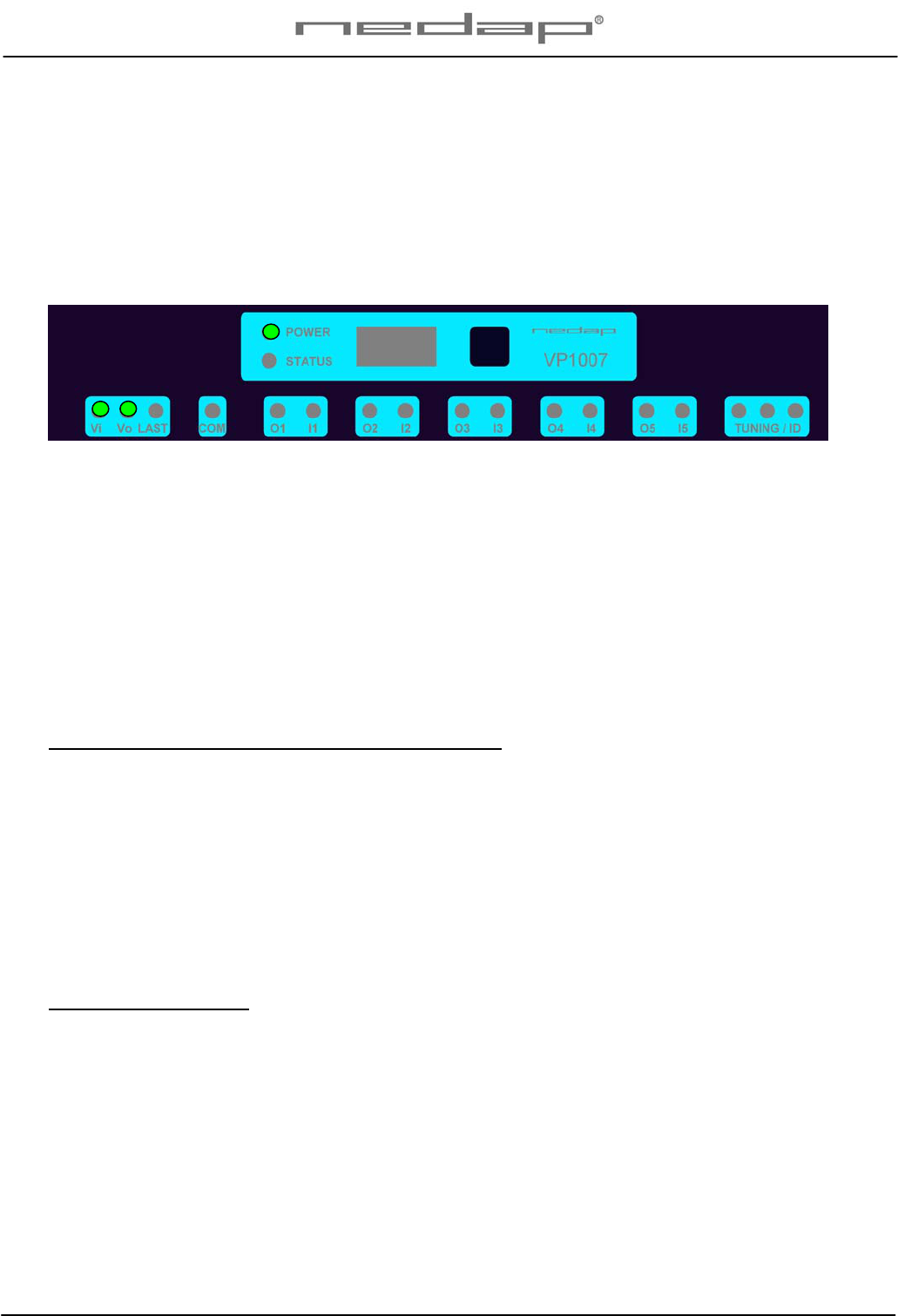
Figure : Sticker on the VP1007 with indication of the connections
Operation of the VP1007
Antenna : for reading tags, normally on
Inputs : read continuously with status change sent to the controller
Outputs : switched on or off by commands from the controller
LEDs : switched on or off by the VP1007 according to the status
Error : errors are sent to the controller
All inputs and outputs can be tested by the use of the push button and display. For operation of the
push button and display see appendix B.

VP1007-200PM-00 ISO Reader I/O Manual version 0.4 / Page 3
3 Safety
Installation and service only by trained personnel.
Always turn off the main power when working on the electrical installation.
4 Installation
Installation consits of the following steps:
1. Mounting
2. Installation of all wiring (connections)
3. Power up
4. Set address (when more then one VP1007)
5. Check antenna adjustment (green LED on)
6. Check the connected equipment like lamps, motors, sensors etc.
7. Configuration in the PC
Follow this manual to complete the steps.
4.1 Mounting
See the relevant equipment manual relating to where the VP1007 is to be installed.
VP1007-200PM-00 ISO Reader I/O Manual version 0.4 / Page 4
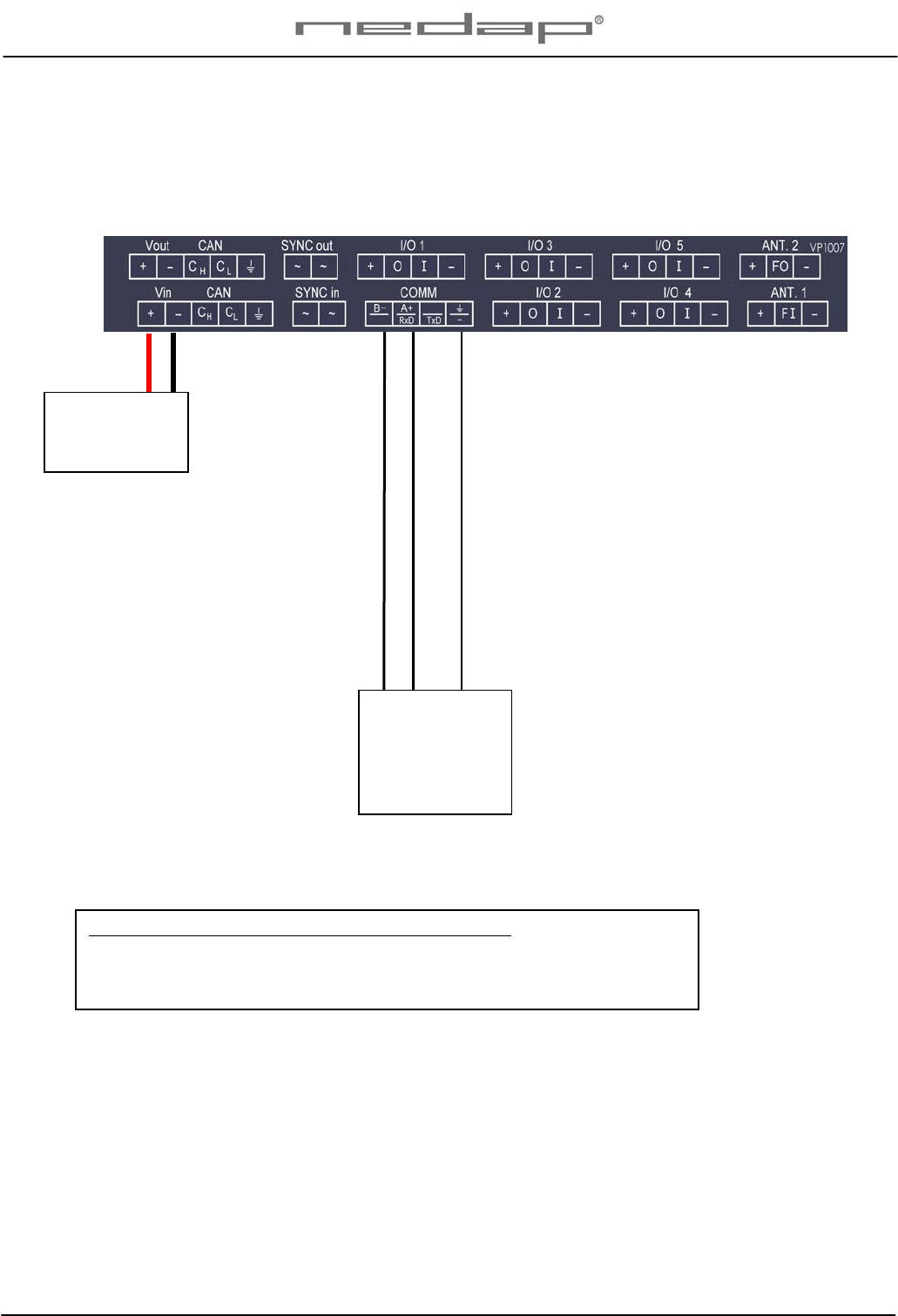
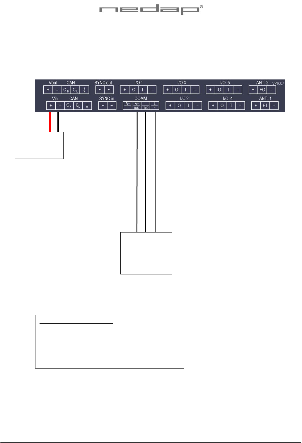
4.2 Connections
See the relevant equipment manual relating to where the VP1007 is to be installed.
Figure : I/O of the VP1007. The input and output connections are shown above as an example.
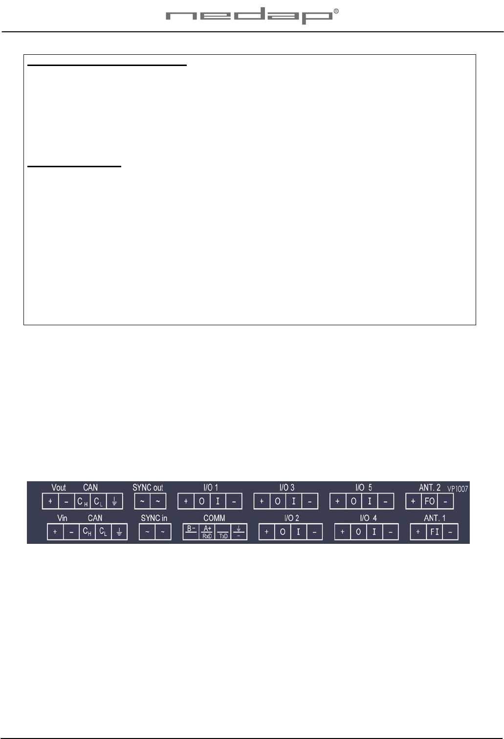
Details VP1007 inputs and outputs
Vin + Power
- Minus
RS232 / 485 RxD / B- Data receive
TxD / A+ Data send
- / Minus for RS232 / shield for RS485
SYNC ~ Synchronisation for HDX, AC (no plus or minus, cable must be twisted pair)
~ See above
I/O 1 .. 5 + Output max 400mA
O Output max 400mA / 1.7A input
- Minus for output (O) and minus input (I)
I Input
ANTENNA + Antenna
F SYNC FI/FO Frequency synchronisation FI=in FO=out
- Antenna minus (shield of coax cable)
IMPORTANT : Use power supply with a fused output such as Velos VP2001, VP2002.
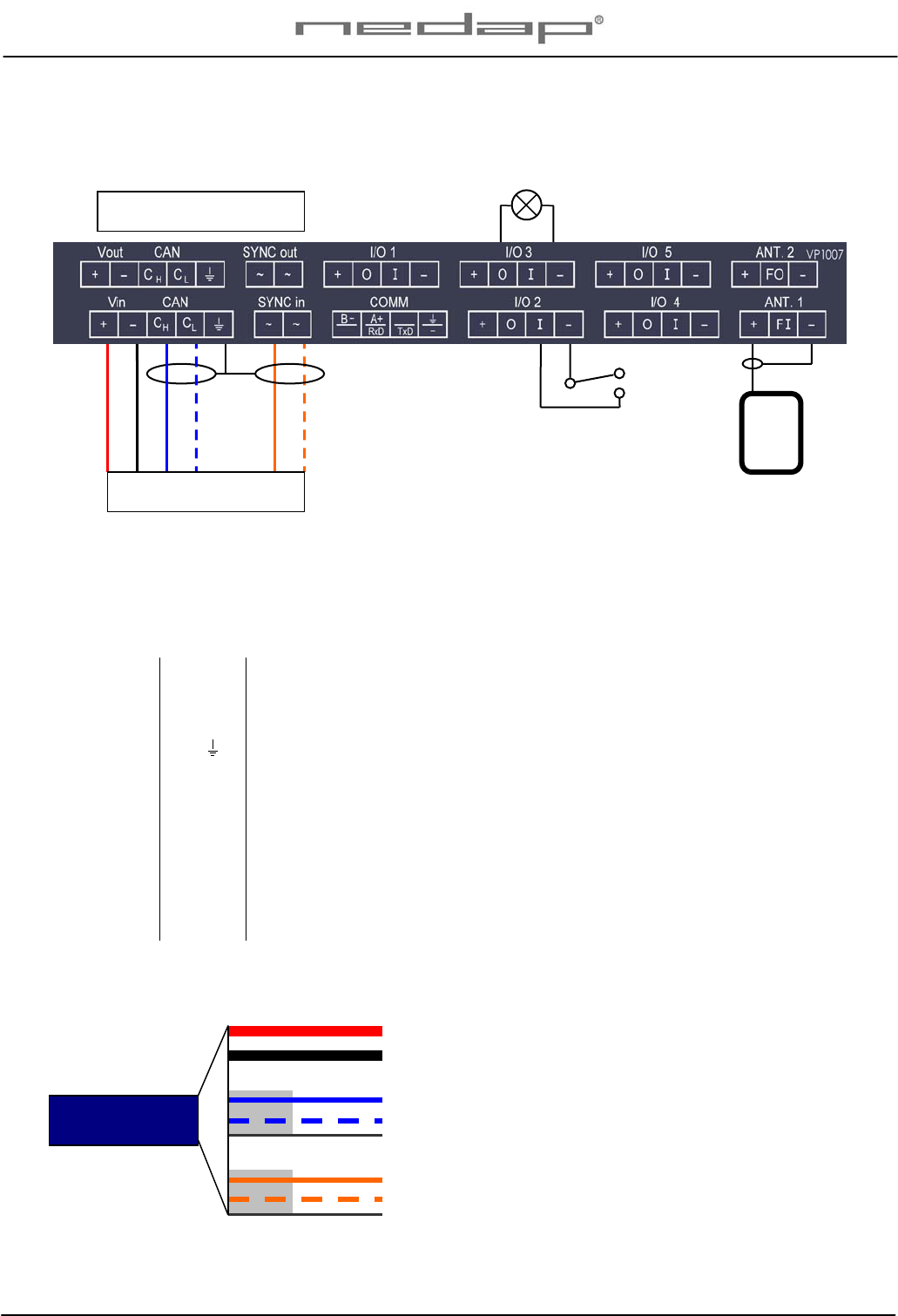
Details Velos cable
oran
g
e
blue white
blue
black
red
orange white
Velos cable
Switch
Light
Velos cable OUT
(
same connection as IN
)
Red (+)
Black (-)
Blue (Ch)
Blue/white (Cl)
Shield
Orange (Sync)
Orange/white (Sync)
Shield
Power
1,5 mm2
Communication
0,34 mm2
Twisted pair shielded
HF Synchronisation
0,34 mm2
Twisted pair shielded
Part No. 7705310
VP1007-200PM-00 ISO Reader I/O Manual version 0.4 / Page 5
5 Adjustments
Before starting with adjustments first install all components and wiring. Follow the sequence as
indicated in this chapter.
5.1 Check after power up
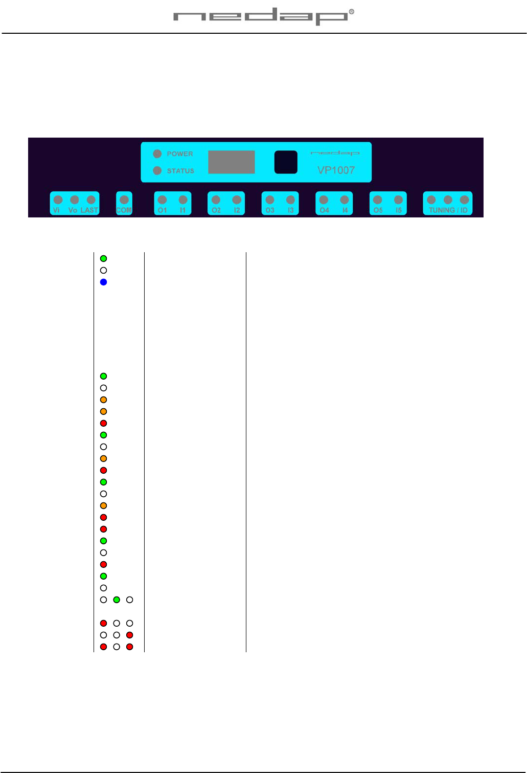
Check if the VP1007 has power after power up. This means 3 green LED’s are on, see figure below.
For more details about the LED indicators see Appendix D.
If LED’s are green, continue with address settings
5.2 Address
Each VP1007 requires a unique address on the communication bus. Use the display and push button
to set the address. How to use the display and push button is shown in appendix B. See appendix C
for the complete overview of the display menu.
The display will indicate the actual address at startup (01 for a new unit). If an address is accepted by
the communication bus the display goes blank. If there is no communication with the controller also the
address is shown. If the address is not accepted, the display will show the address.
How to change an address (for example set address to 12)
1. Short press on the button. Ad will appear.
2. Now hold the button till the display starts blinking. dA will appear.
3. Short press on the button. SA will appear.
4. Now hold the button until the display starts blinking. 0- will appear.
5. Short press on the button. The 0- is now changed into 1-.
6. Hold the button until the display starts blinking. 10 will appear.
7. Short press on the button. The 10 is now changed into 11.
8. Short press on the button again. The 11 is now changed into 12.
9. Hold now the button until the display starts blinking. The 12 is now stored in the memory.
10. There will now be 12 blinking on the display now. If the address is accepted by the process
unit the display goes blank.
How to check the address
1. Short press the button. Ad will appear.
2. Now hold the button until the display starts blinking. dA will appear.
3. Hold the button again until the display starts blinking. The actual address will be shown.
4. Leave the menu by pressing the button until the display goes blank.
If the display does not go blank (address remains on the display), the address in not accepted.
When the address setting is ok continue with the antenna adjustment.

VP1007-200PM-00 ISO Reader I/O Manual version 0.4 / Page 6
5.3 Antenna
After power up the antenna tuning starts automatically. LEDs are indicating the status.
Green on Antenna tuning ok
Red on Antenna out of range
Red on Antenna out of range
Red blinking No antenna connected or low antenna signal
All off Antenna switch off by the software
5.4 Software setup
The software in the connected controller determines how the inputs and outputs on the VP1007 are
controlled. See manual with the relevent settings to configure the software for this VP1007.
When the software setup is done the VP1007 is ready for use.

VP1007-200PM-00 ISO Reader I/O Manual version 0.4 / Page 7
6 Advanced
Tests and adjustments described in this chapter are not used for a standard startup and configuration
of the VP1007.
6.1 Testing inputs and outputs
Output test
Use the test L1, L2, .. L5 to test the connected equipment e.g. lights, valves or relays. This test will
switch on the selected output. The test is stopped by a short press on the button.
Example of a light test (connected to output 5)
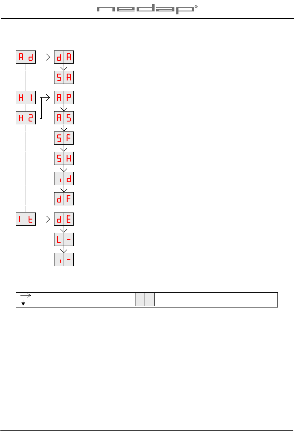
1. Short press on the button until “It” appears.
2. Now hold the button until the display starts blinking. “dE” will appear.
3. Short press on the button until “L5” appears.
4. Now hold the button until the display starts blinking. Output 6 will be switched on. To switch off,
a short press on the button.
Input test
Use the test i1, i2, .. i5 to test the connected equipment e.g. switches and sensors. This test will read
the selected input. The results are indicated with a “0” or “1”. Open or closed depends on the settings
from the behavior component. The test is stopped by a short press on the button.
Example of a switch test (connected to output 5)
1. Short press on the button until “It” appears.
2. Now hold the button till the display starts blinking. “dE” will appear.
3. Short press on the button until “i5” appears.
4. Now hold the button until the display starts blinking. Input 5 will be read.
5. Activate the switch on and off. If ok, the display value will show zero and one
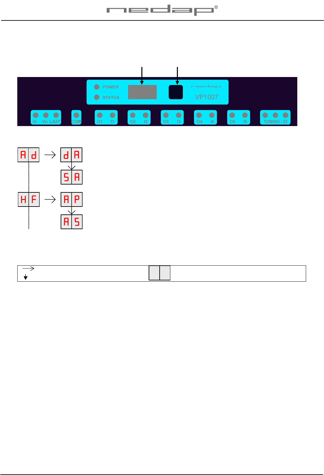
6.2 Advanced antenna adjustment
Antenna power
The antenna power default is set to maximum (99) and needs no adjustments.
Lowering the antenna power will reduce the reading distance of the antenna.
Check the antenna power
The antenna power level is shown on the display in the service menu at HF option AP (Adjust Power)
1. Select menu option AP (Adjust Power) on the display by using the push button
2. Push the button until the display starts to blink, a value will appear on the display
3. The value on the display is the actual power setting. 99 is the default factory setting.
4. To leave the menu without modifying the settings press the button until the display goes blank
(press about 4 seconds)
Modify the antenna power
1. Select the actual antenna power on the display (see above antenna power check)
2. Short press on the button and the first digit of the value will change
3. Continue to press until the desired value, then hold the button until blinking
4. The second digit can be changed in the same way
5. When the desired value is on the display, press until the display blinks
6. The next menu item AS is now indicated.
7. To leave the service menu and return to normal operation, press the button until the display
goes blank (press about 4 seconds)

VP1007-200PM-00 ISO Reader I/O Manual version 0.4 / Page 8
Antenna squelch
Antenna squelch is a possibility to set a threshold for the ID level of a tag. It means the antenna power
is still the same, but the software will not transfer weak received tag numbers.
The antenna squelch default is set to minimum (-0). This means no threshold. Maximum is -9.
Check the antenna squelch level
The antenna squelch level is shown on the display in the service menu at HF, option AS (Adjust
Squelch)
1. Select menu option AS (Adjust Squelch) on the display by using the push button
2. Push the button until the display starts to blink, a value will appear on the display
3. The value on the display is the actual setting. -0 is the default factory setting.
4. To leave the menu without modifying the settings press the button until the display goes blank
(press about 4 seconds)
Modify the antenna squelch level
1. Select the actual antenna squelch level on the display (see above squelch level check)
2. Short press on the button and the value will change
3. Continue to press until the desired value, then hold the button until blinking
4. The next menu item “df” is now indicated.
5. Hold a tag in the antenna and determine the maximum reading distance
6. If reading distance is ok leave the menu. If not ok try another level.
7. To leave the service menu and return to normal operation, press the button until the display
goes blank (press about 4 seconds)
6.3 Identification test options
Identification test with option “id”
When a tag is in the antenna field, the green LED used for the antenna tuning will be blinking. There is
also a test in the internal test menu called “id”. This test will also show the green LED blinking but also
shows the last two digits of the tag number on the display.
Signal level indication option “SF” and “SH”
There is a test available to give an indication about the signal received on the reader of the VP1007.
This test is separated in a FDX (SF) and HDX (SH) noise indication test. This test is mainly used for
HDX because at HDX there is a greater risk of external influence on the antenna field.
How to use the signal level test
1. Select option “SH” on the display and press the button until the display starts to blink. A value
will appear on the display.
2. Now move a HDX tag slowly into the antenna field. The display value will normally increase
when getting closer to the antenna. If there is negligible or little increase in display value this is
an indication something external is causing noise.
The possible cause of noise can be frequency controlled electric motors or a transmitter operating on
or close to 134.2 kHz

VP1007-200PM-00 ISO Reader I/O Manual version 0.4 / Page 9
7 Trouble shooting
Errors / malfunctioning is indicated by the indicator LED’s or the display.
Error by indicator LED
Indicator LED’s are normally green or switched off. A red or orange indicator LED means normally
there is something not ok. See Appendix D for the explanation of the different colors.
Errors indicated at menu option “dE”
In menu option “dE” it is possible to see actual error codes. When entering the display menu option
“dE” the errors code will be shown and the error will be cleared. If the error is not cleared it means
there is still an error. There can be more than one error. Further errors are displayed one after another
with a short delay between each code.
“dE” code on the display Description
00 No errors
01 Max I out error, next module shut off
02 Short circuit detected at reset
03 Max I out high-side
04 Max I out low-side
05 CAN over voltage
06 CAN offset too high
07 -
08 -
09 Short circuit out5 <-> minus
10 Short circuit out4 <-> minus
11 Short circuit out3 <-> minus
12 Short circuit out2 <-> minus
13 OUT1 off : +24V on OUT1
14 Short circuit out1 <-> minus
15 IO5 off: +24V on OUT5
16 IO5 on: short circuit IO5
17 IO4 off: +24V on OUT4
18 IO4 on: short circuit IO4
19 IO3 off: +24V on OUT3
20 IO3 on: short circuit IO3
21 IO2 off: +24V on OUT2
22 IO2 on: short circuit IO2
23 IO1 off: +24V on OUT1
24 IO1 on: short circuit IO1
Identification performance and disturbance
Identification performance can be reduced by disturbance caused by variable-frequency drives used
for ventilation, milk pumps, vacuum pumps, etc. Also ballasts used for fluorescent tube lighting may
interfere. If there is interference one can locate the source by switching off all the equipment on a farm
and then switch them on again one by one. Most of the time when a variable-frequency drive is
causing a problem it is due to bad installation or without the mandatory main filters.

VP1007-200PM-00 ISO Reader I/O Manual version 0.4 / Page 10
8 Maintenance, cleaning and disposal
Maintenance
No regular maintenance required.
Software update
A VP1007 is equipped with software to activate inputs and outputs, display / push button and a motor
safeguard. This software is called firmware. During manufacturing the firmware is programmed and
ready for use. In case of an update it is possible to download new firmware thru the CAN-bus. In the
Velos system the web browser interface of the VPU (VP8001) is used to handle this. For more details
about downloading new firmware see also the manual of the VPU (VP8001).
Cleaning
A VP1007 must be installed in a suitable housing (V-box) so cleaning of the VP1007 is not required.
Disposal
Discard according to the regulations prevailing at the time of disposal

VP1007-200PM-00 ISO Reader I/O Manual version 0.4 / Page 11
Appendix A: Specifications
Specifications VP1007 (part no 9926542)
Dimensions 143 x 120 x 68 mm LxWxH (excluding mounting rail) Weight: ± 360 gr
Power Input voltage 25 VDC, +20% -20%
Minimal power consumption 300 mA with antenna switched on
Maximum power consumption 4,5 A
Protected against reverse connection power supply
Communication CAN, RS485 and RS232
Software Downloadable thru network
Inputs Reading inputs, analog (0-40V) and digital.
Suitable for NPN and PNP sensors.
Outputs Max. +0.4 / -1.7 Amp by current limiter, short-circuiting protected
I/O safe-guard when total I/O current > 4A
Antennas Different types possible
Detection distance Varies per antenna
Synchronisation Synchronization according to ISO 11785
Environment Temperature: Operating: -10 – 50 °C, Storage: -25 – 70 °C
Relative humidity: 10 – 93% non condensing
IP class IP 30. When installed in V-box IP 65 (cover and cables installed correctly!)
Cable specifications
Power
CAN-bus Min. 1.5 mm2
Min. 0.34 mm2 twisted pair shielded
Antenna Coax RG58. Max. length depending on antenna type.
Outputs CE approved at cable length < 3m
Inputs CE approved at cable length < 3m
Synchronisation Twisted pair min. 0.34mm2 shielded Total max. 500m
Always use a NEDAP power supply
The Nedap guarantee-regulations are only valid when is installed as indicated in this manual.
Install data cables at a safe distance from (high) powered cables
More information
For more detailed information contact your local Nedap supplier or check the internet site.
VP1007-200PM-00 ISO Reader I/O Manual version 0.4 / Page 12
Appendix B: Display and push button
DISPLAY ADDRESS
Shows the actual address
SET ADDRESS
Change the address
ANTENNA POWER
Min/max 10 / 99. Normally set to 99. Possible to set a lower value.
ANTENNA SENSITIVITY SQUELCH
Min/max 9 / 0. Normally set to 0. Possible to set a lower value.
Figure: a section of a display menu
Press button until blinking
Short press on button To leave menu:
Press button until display goes blank
How to use the display and push button
Normally the display is off. If there is no connection to the VPU the address is shown. It is also possible
some program states of a behavior component are shown during operation.
Activate the menu short press on the button, the display menu is shown
Scroll down short press on the button
Select press button until blinking
Change and store select item to change, open item by pressing button until blinking, change by
short press on button, store by pressing button until blinking
Check a setting select the item to check, press button until blinking, first value shown is actual
setting
The display is normally automatically switched off after 30 minutes.
Display Push button
VP1007-200PM-00 ISO Reader I/O Manual version 0.4 / Page 13
Appendix C: Overview display menu
DISPLAY ADDRESS
Shows the actual address
SET ADDRESS
Change the address
ANTENNA POWER
Min/max 10 / 99. Normally set to 99. Possible to set a lower value.
ANTENNA SENSITIVITY SQUELCH
Min/max 9 / 0. Normally set to 0. Possible to set a lower value.
SIGNAL LEVEL FDX
Shows signal level measured by the FDX receiver
SIGNAL LEVEL HDX
Shows signal level measured by the HDX receiver
TEST IDENTIFICATION
Shows last 2 digits of a tag number
SETTINGS TO DEFAULT
All HF settings back to factory settings
DISPLAY ERROR
Shows error code
TEST OUTPUT
L1 … L5
TEST INPUT
I1 … i5
REMARK
Press button until blinking
Short press on button To leave menu:
Press button until display goes blank
VP1007-200PM-00 ISO Reader I/O Manual version 0.4 / Page 14
Appendix D: LED indicator overview
POWER Green on Power on
off No power
STATUS Blue
Slow blinking
Fast blinking
1 short flash
2 short flashes
3 short flashes
Operating ok
Downloading or error during download
V-pack not coupled
Firmware present but not active
No firmware present
Display on Address indicated No communication
off Communication status ok
Vi Green on Input power applied
off No power
Orange Low power, less than 20V
Orange blinking Wrong CAN-bus connection, Vin and Vout swapped
Red Error, plus and minus swapped / overload
Vo Green on Output power
off No power
Orange blinking Low power
Red blinking Error, plus and minus swapped
COM Green on V-pack is last one on the bus
off V-pack is not last one on the bus
Orange blinking CAN-bus error and last V-pack on the bus
Red CAN-bus error
Red blinking CAN-bus warning / connected wrong
O1 .. O5 Green on Output on
off Output off
Red blinking Output error / overload
I1 .. I5 Green on Input contact open
off Input contact closed
TUNING /ID Green on
Green blinking Antenna ok
Antenna ok and tag identified
Red on Antenna not tuned correctly
Red on Antenna not tuned correctly
Red blinking Antenna error / not connected
VP1007-200PM-00 ISO Reader I/O Manual version 0.4 / Page 15
Appendix E: RS485 connection
RS 485 port of
computer
B
A
shield
Power supply
RS485 cable specifications (computer to first VP1007):
Wires : min. 0.34 mm2 twisted pair shielded
Max length between computer and VP1007 100m.
Longer length depends on used baudrate used.
VP1007-200PM-00 ISO Reader I/O Manual version 0.4 / Page 16
Appendix F: RS232 connections
RS 232 port of
computer
RxD
TxD
GND
RS232 cable specifications :
Shielded cable
Wires min. 0.34 mm2
Max length between Computer and VP1007 3m.
Power supply