Nedap N V VP1850 Inductive Card Reader User Manual 01
N. V. Nederlandsche Apparatenfabriek NEDAP Inductive Card Reader 01
Contents
- 1. User manual 01
- 2. User manual 02
User manual 01
Panel Reader
VP1850
Manual article number 5277027 February 2011 / Manual version 1.2
Service manual
For installation, operation and service
VP1850-200PM-00GB-Panel reader Manual version 1.2
Preface
This manual describes the installation, operation, troubleshooting and maintenance of the
VP1850 Panel reader. Read this manual entirely and when installing, carefully follow the
instructions step by step as described in the manual.
Pictograms
Please pay extra attention here. This pictogram indicates an important subject.
Version overview
Manual version 1.0 / May 2010 First release.
Manual version 1.1 / October 2010 Wiring adjusted.
Manual version 1.2 / February 2011 IP utility wizard instructions for CD adjusted.
This information is furnished for guidance, and with no guarantee as to its accuracy or completeness; its publication conveys no
license under any patent or other right, nor does the publisher assume liability for any consequence of its use; specifications and
availability of goods mentioned in it are subject to change without notice; it is not to be reproduced in any way, in whole or in part,
without the written consent of the publisher.
© Nedap N.V., AGRI P.O. Box 104 NL-7140 AC GROENLO The Netherlands
MODEL: VP1850 VELOS
IC: 1444A-VP1850 and FCC ID: CGDVP1850
Compliance statements
This device complies with part 15 of the FCC Rules and to RSS210 of Industry Canada.
Operation is subject to the following two conditions:
(1) this device may not cause harmful interference, and
(2) this device must accept any interference received, including interference that may cause undesired operation.
Cet appareil se conforme aux normes RSS210 exemptés de license du Industry Canada. L'opération est soumis aux
deux conditions suivantes:
(1) cet appareil ne doit causer aucune interférence, et
(2) cet appareil doit accepter n'importe quelle interférence, y inclus interférence qui peut causer une opération non
pas voulu de cet appareil.
Warning (part15.21)
Changes or modifications not expressly approved by party responsible for compliance could void the user’s authority
to operate the equipment.
This in particular is applicable for the antenna which can be delivered with the System.

VP1850-200PM-00GB-Panel reader Manual version 1.2
Table of contents
Preface and Version overview
Table of contents
1. Introduction .........................................................................................................................1
1.1. Description ............................................................................................................................1
1.2. Functioning............................................................................................................................1
2. Mounting the VP1850 Panel reader...................................................................................3
3. Starting up operation..........................................................................................................4
3.1. Connecting the VP1850 Panel reader ..................................................................................4
3.2. Setting up the network configuration ....................................................................................5
3.3. Setting up the VP1850 Panel reader software .....................................................................6
4. Operation .............................................................................................................................8
5. Malfunctions and disposal.................................................................................................9
5.1. Trouble shooting ...................................................................................................................9
5.2. Resetting the VP1850 Panel reader ...................................................................................10
6. Maintenance and disposal ...............................................................................................11
6.1. Maintenance........................................................................................................................11
6.2. Disposal ..............................................................................................................................11
Appendix A Technical specifications..................................................................................12
Appendix B Wiring Panel reader .........................................................................................13
Appendix C Corridor requirements.....................................................................................15
VP1850-200PM-00GB-Panel reader Manual version 1.2 / Page 1
1. Introduction
The VP1850 Panel reader identifies RFID ear tags attached to individual animals. The
identification can be used for registration of the animals that have passed the VP1850 Panel
reader unit. A weight scale can optionally be connected to the Panel reader.
This device complies with Part 15 of the FCC Rules and to RSS-210 of Industry Canada.
Operation is subject to the following two conditions: (1) this device may not cause
harmful interference, and (2) this device must accept any interference received, including
interference that may cause undesired operation.
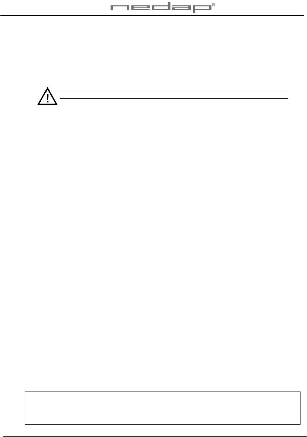
1.1. Description
The VP1850 Panel reader system consists of a Panel reader unit that is connected to an
adaptor, a PC or a network or optionally a weight scale.
1. VP1850 Panel reader
unit
2. Adaptor
3. PC
4. Optional Weight scale
5. Blue tooth connection
6. GPS connection
Figure 1. Overview VP1850 Panel reader system
1.2. Functioning
The VP1850 Panel reader creates a magnetic field around the antenna that is used to identify
the tags on ISO frequency 134.2 kHz. The Panel reader antenna identifies RFID ear tags
attached to individual animals that pass the Panel Reader unit. The identification is indicated
with five blue burning led lights in the top of the Panel reader.
Figure 2. Identification blue led lights
3
2
1
Weight
scale 4
5
6
OR
VP1850-200PM-00GB-Panel reader Manual version 1.2 / Page 2
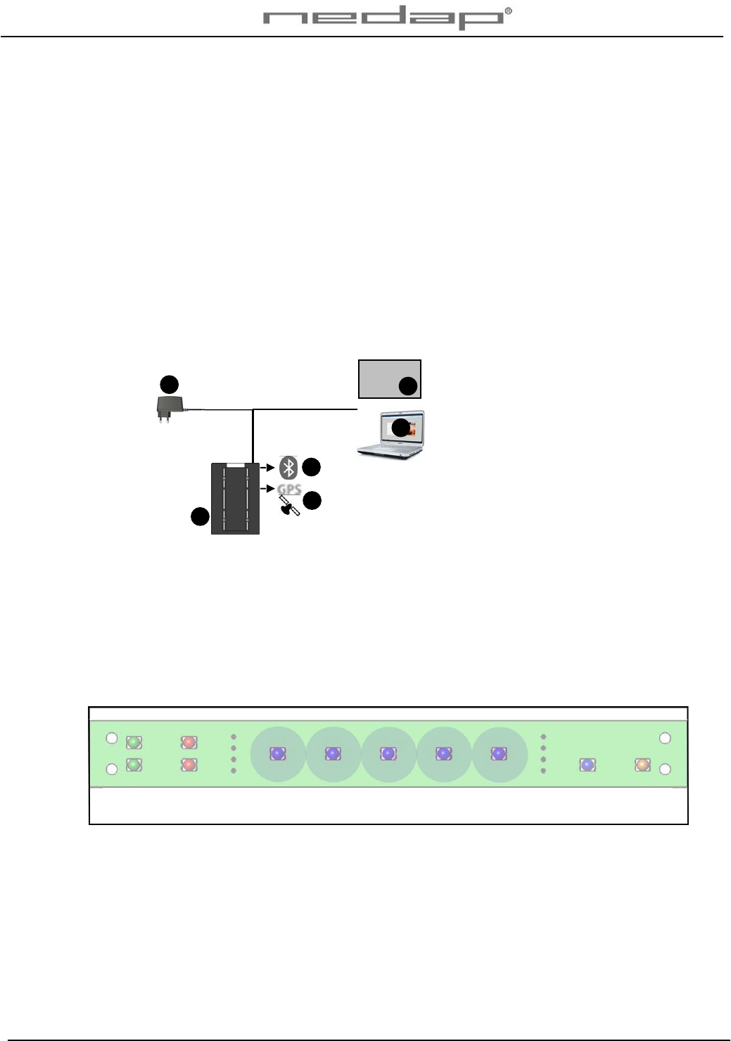
When an animal is identified in the Panel reader antenna, the responder number will be stored.
The responder number will be shown in the web server program. A PC or a network is used to
access the web server (and the Internet worldwide). It does not have to be connected all the
time.
1. VP1850 Panel reader
unit
2. Responder number
(animal identification)
3. Data in web server
program
Figure 3. Connection between VP1850 Panel reader and web server program
3
1
2
VP1850-200PM-00GB-Panel reader Manual version 1.2 / Page 3
2. Mounting the VP1850 Panel reader
See Appendix A for technical specifications before mounting. See Appendix C for corridor
requirements.
Mounting requirements:
1. The Panel reader must be mounted at the side where the ear tags of the animals
are attached.
2. The Panel reader must be mounted on a wall close to a stable power supply.
3. The Panel reader must not be mounted close to any iron. Iron will affect the
performance of the antenna.
4. The Panel reader must be mounted > 1.5 m. from electrical cables or power supply /
transformers.
5. The Panel reader must not be mounted close to electrical equipment (e.g. a power
supply) with background noise. This can disturb the antenna.
6. The Panel reader may not be exposed to direct sunlight.
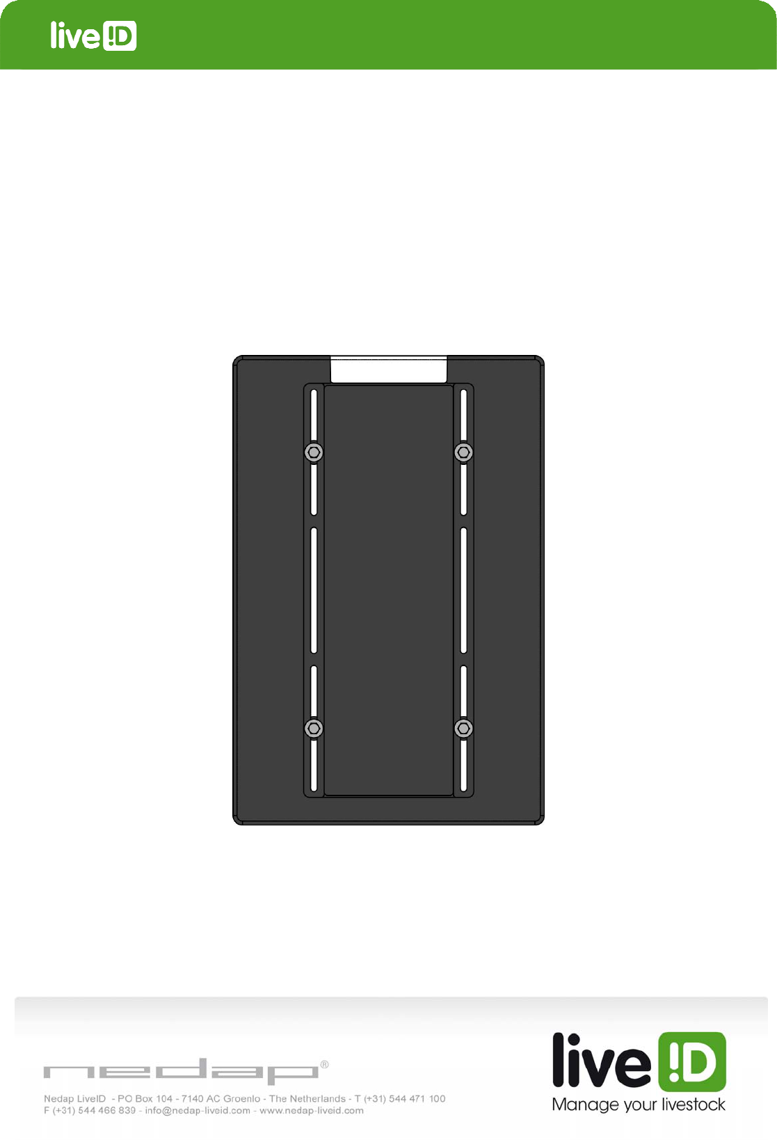
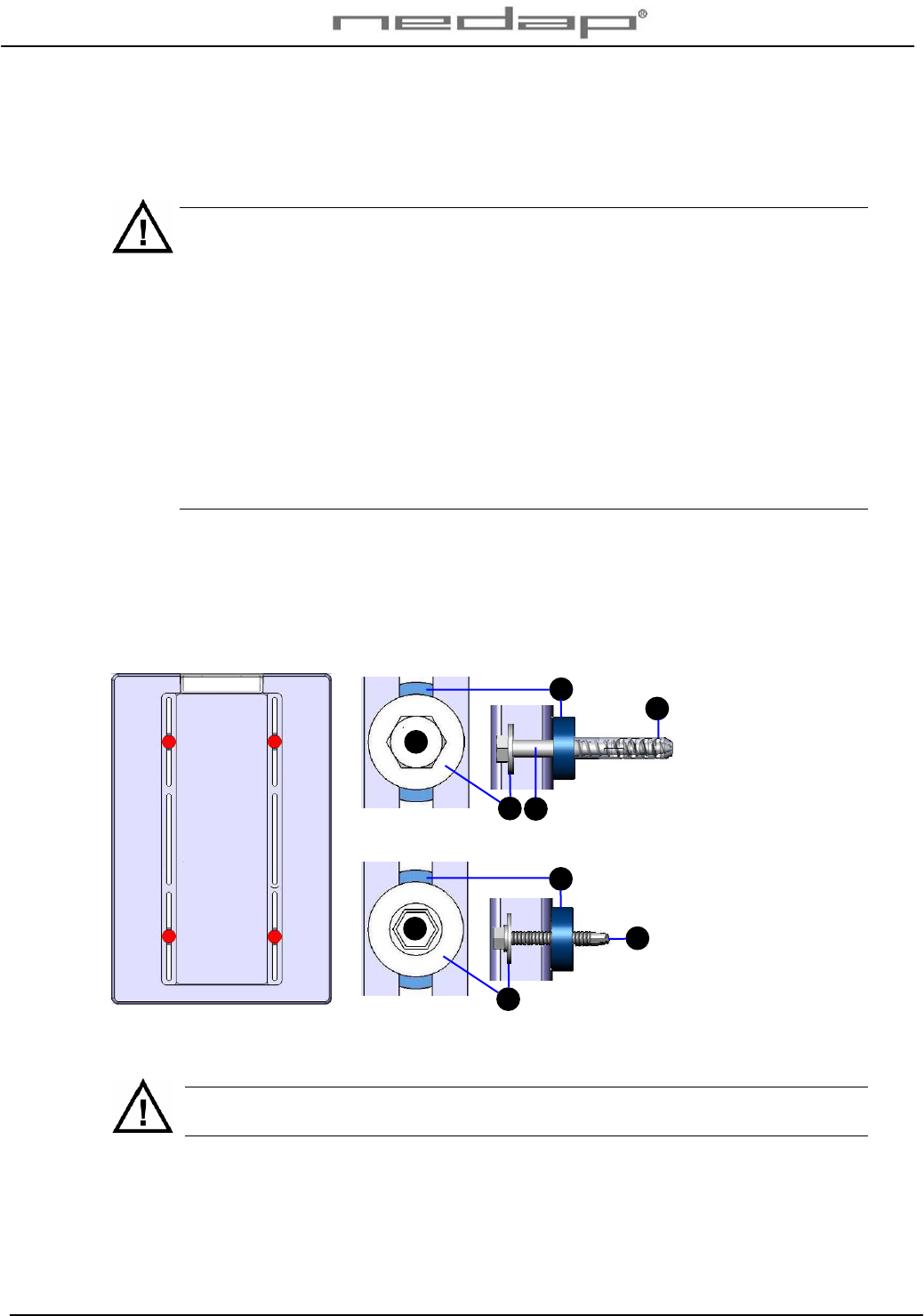
Mount the VP1850 Panel reader unit firmly on a wall or at a (non metal) frame.
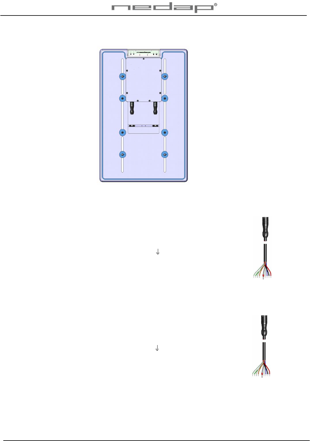
1. Drill ø10 and at least 50 mm deep holes to mount the Panel reader in the 4 positions
indicated in the picture below.
2. Use the bolts that are supplied with the unit to mount the Panel reader. Use the 4 big bolts
for a wall or the 4 smaller ones for a metal surface.
For wall: Bolt, washer,
spacer and plug (4x)
A. Bolt
M8x80 DIN 571
2. Plain washer
M8 DIN 9021
3. Spacer
4. Nylon plug 10x50
For metal: Bolt, washer
and spacer (4x)
B. Bolt
M6.3x50 DIN 7504
2. Plain washer
M8 DIN 9021
3. Spacer
Figure 4. Mounting positions for the VP1850 Panel reader
General remark: Don’t drill through the Panel reader. This could damage the
electronics and affect the functioning of the Panel reader.
3
2
BB
A
2
3
A
4
VP1850-200PM-00GB-Panel reader Manual version 1.2 / Page 4
3. Starting up operation
The VP1850 Panel reader is pre-tuned and ready for use.
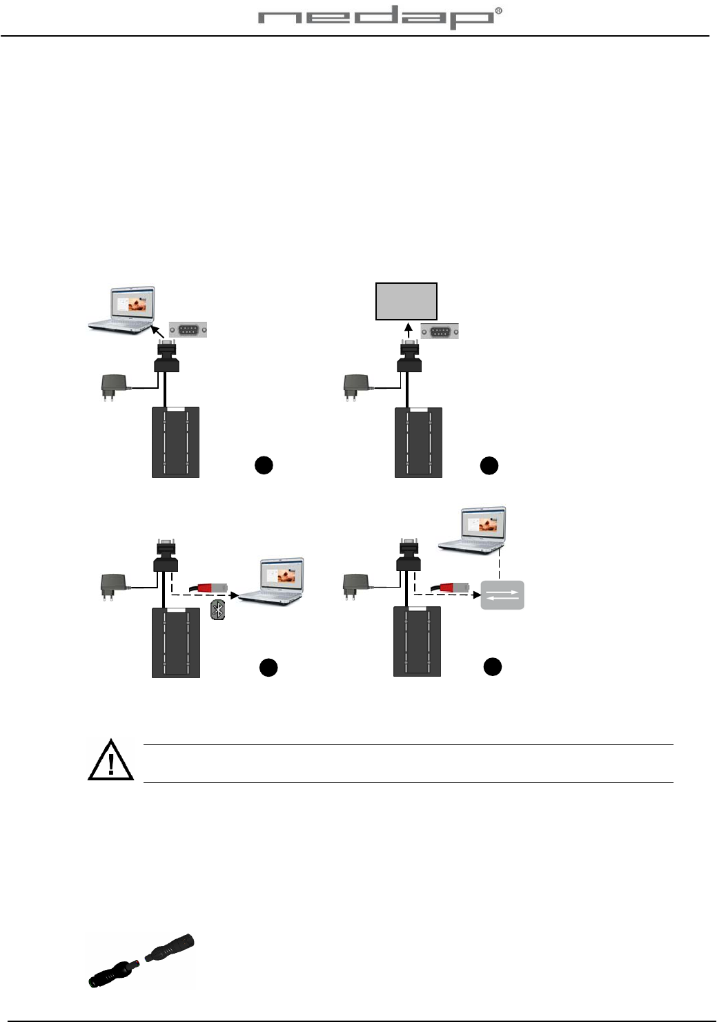
3.1. Connecting the VP1850 Panel reader
Connect the VP1850 Panel reader to a PC or a weight scale through an RS232 connection or to
a PC or router through a LAN (or Bluetooth) connection. The Panel reader is already connected
to the adapter through the connector. The adapter is optionally used when connected to a
weight scale (depends on weight scale type). See appendix B for a wiring scheme of the Panel
reader cable.
1. RS232 connection with
PC
2. RS232 connection with
weight scale or other
device and optional
adaptor
3. Bluetooth or LAN
connection with PC
4. LAN connection with
router
Figure 5. Overview VP1850 Panel reader system to be connected
Connect the VP1850 Panel reader to a PC or a network and optionally to a weight scale.
Install cables and power supplies / transformers > 1.5 m. from the Panel reader if
possible.
3. Connect a PC to the Sub-D connection from the connector if there is no weight scale or
connect a PC via the Bluetooth or LAN connection or connect a network via the LAN
connection.
4. Optionally connect a weight scale to the Sub-D connection from the connector.
5. Put the adaptor into an electric socket.
6. Check the operation of the Panel reader.
Use an extension cable (art. nr 7707037) of 4 meters to extend the Velos
Panel reader cable if necessary.
13
Weight
scale
4
2
VP1850-200PM-00GB-Panel reader Manual version 1.2 / Page 5
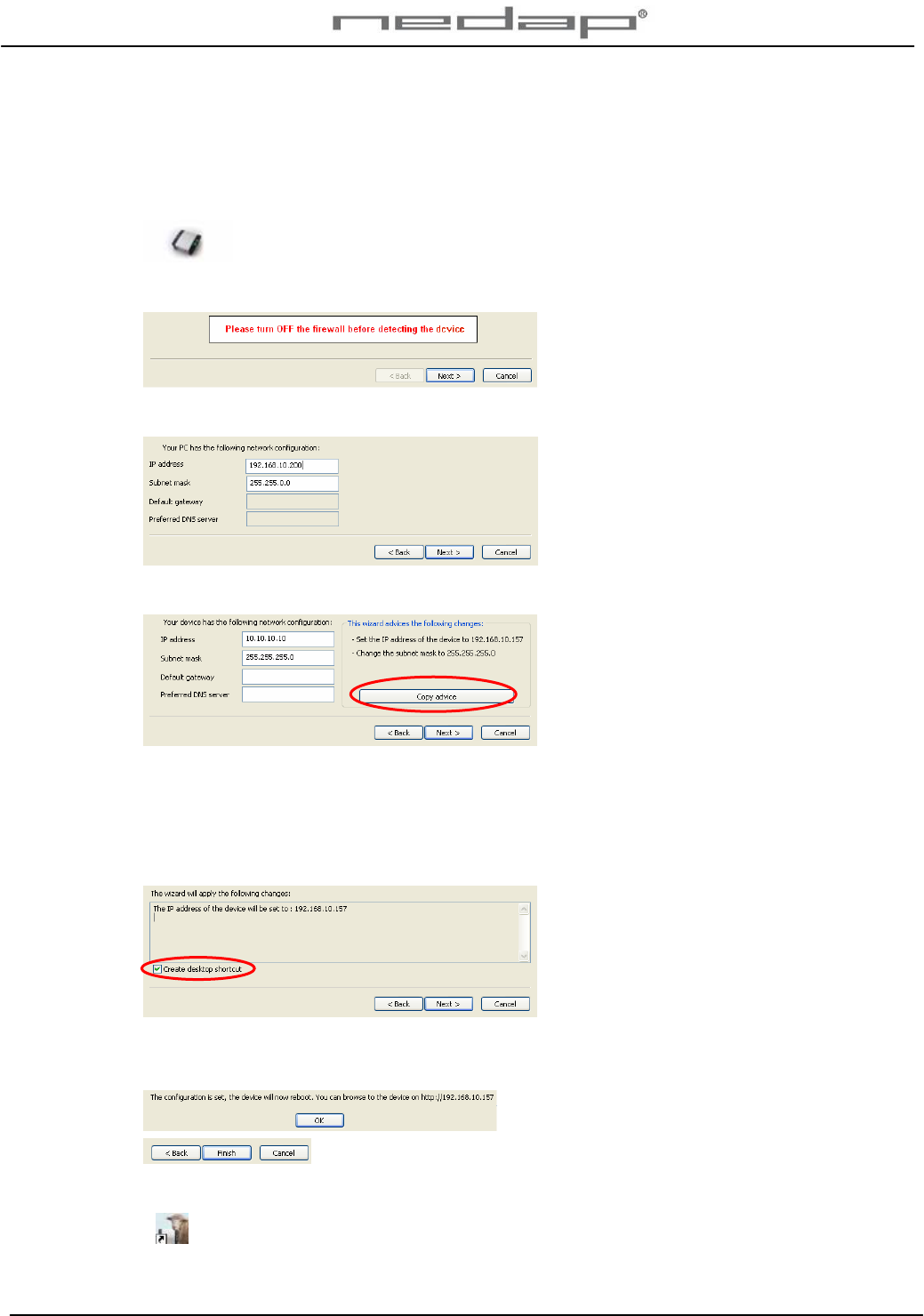
3.2. Setting up the network configuration
Make sure the VP1850 Panel reader is connected to the network and is operating. Take the IP
Utility wizard CD and run it on the connected PC to set the IP address correctly.
1. Click on the IP utility wizard icon from the IP wizard CD.
2. Turn off the fire wall (in the Control panel - Security centre) and click Next.
3. Click Next.
4. Click on copy advice if this is suggested and click Next.
If the VP1850 Panel reader is not found check if the Panel reader is running and if the
network is connected correctly. Click Back and try again. Contact a network specialist if
necessary.
5. Click Next. The IP address will now be changed and a web server program shortcut will
be created on the desktop.
Click OK.
6. Click on OK and on Finish.
7. The web server program shortcut is now on the desktop. Click on it to start the program.
VP1850-200PM-00GB-Panel reader Manual version 1.2 / Page 6
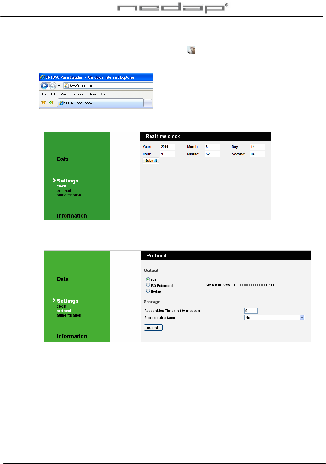
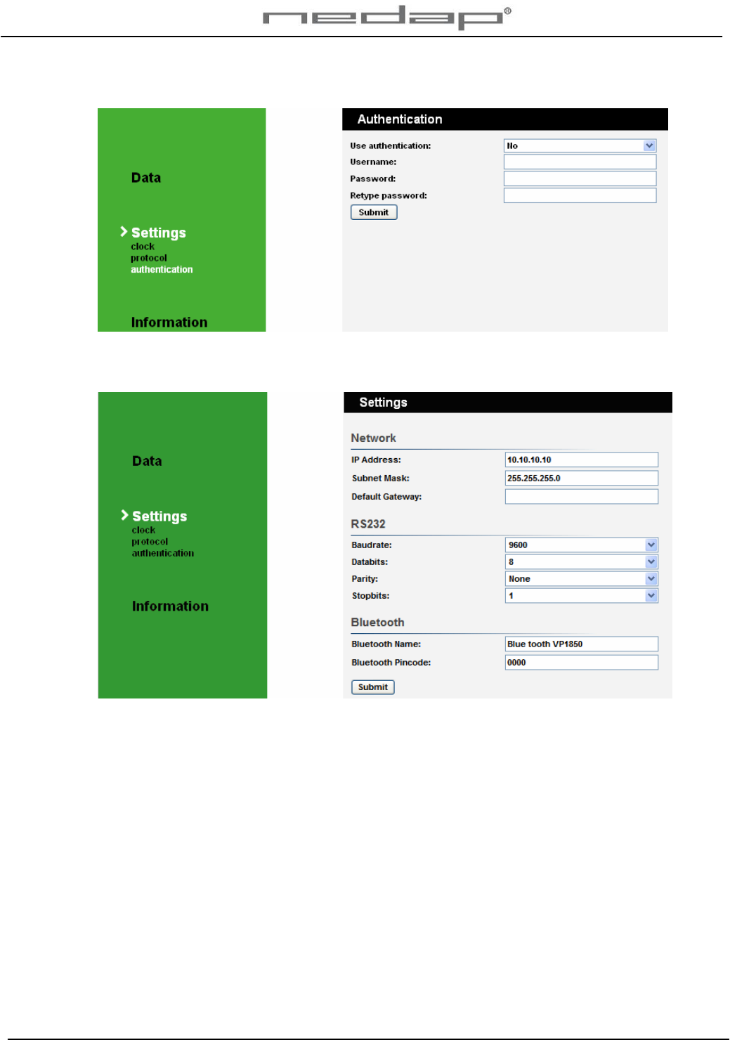
3.3. Setting up the VP1850 Panel reader software
Click on the web server shortcut icon on the desktop to start the web server program if
available or open the web browser with the IP address set with the IP Utility wizard (factory
default http://10.10.10.10).
1. Set the clock time in the screen Settings > Clock and press Submit. Press refresh or F5 to
get the new value from the Panel reader.
2. Change the output and storage protocol if necessary in the screen Settings > Protocol and
press Submit. The output and storage settings will influence the output data that will be
send by the RS232 and the Bluetooth every time a number is read.
The default and recommended output setting is: ISO extended.
Output protocol:
• ISO: output data send according ISO standards.
• ISO Extended: output data send according to ISO standards, including timestamp.
• Nedap: output data send according to Nedap Velos protocol.
For advanced user: In UDP the number is sent real-time.
The default and storage settings are: Recognition time 5 and store double tags No.
• Store double tags Yes: store the identification time of double tags in the same file.
• Store double tags No: store only the last identification time.
VP1850-200PM-00GB-Panel reader Manual version 1.2 / Page 7
3. Optionally enter a user name and password. Especially when the Panel reader is
integrated in a network this is advised.
4. Change the RS232 and Bluetooth settings in the Settings screen if necessary and press
Submit. The network settings have been made in § 3.2.
The default RS232 settings are: Baud rate 9600, Data bits 8, Parity None and Stop bits 1. The
default Bluetooth name is BlueMod+B20 %:4a and the default security pin code is 0000. These
settings can be changed.
VP1850-200PM-00GB-Panel reader Manual version 1.2 / Page 8
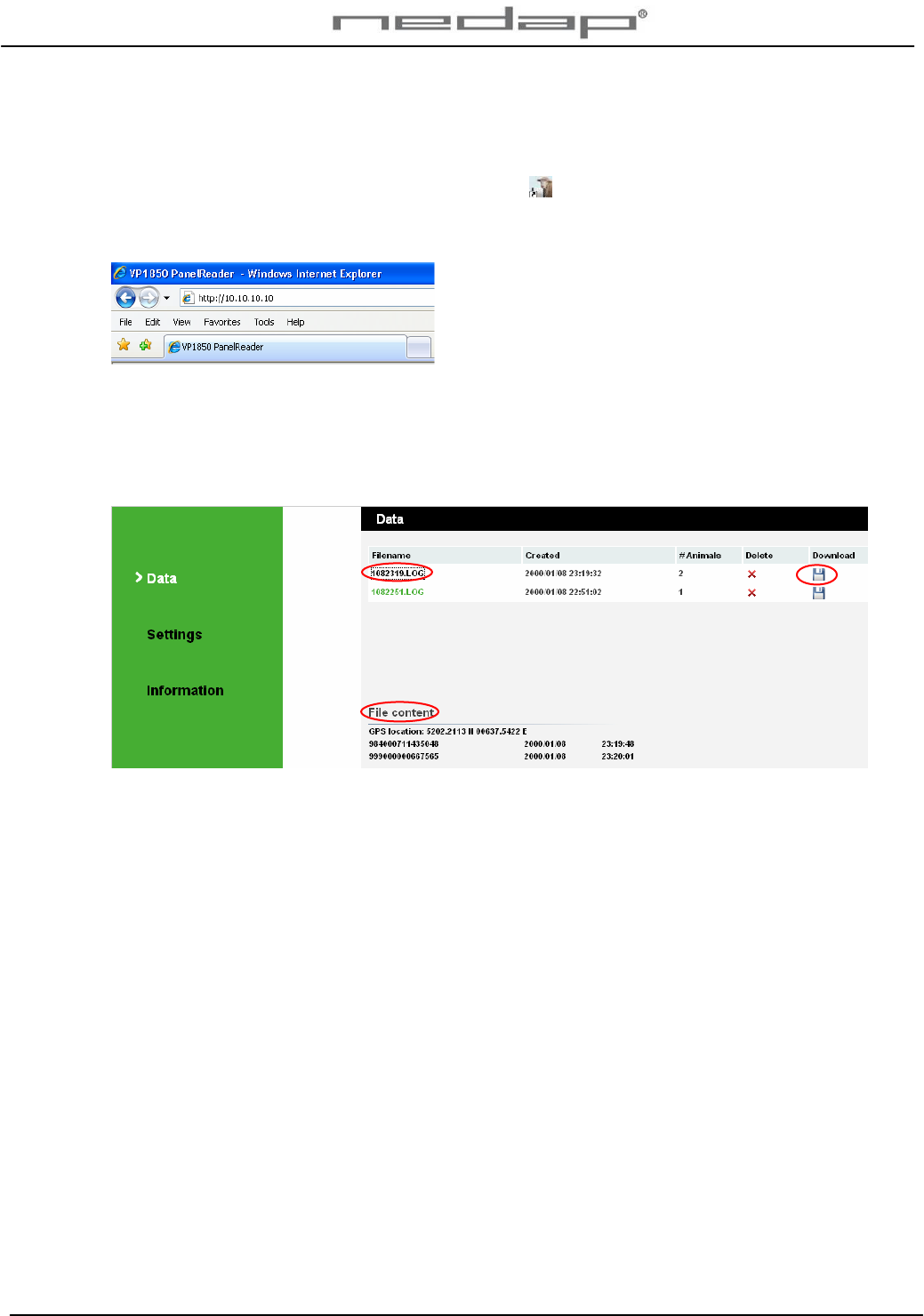
4. Operation
The Panel reader web server data program can be opened and operated on a PC.
Click on the web server shortcut icon on the desktop to start the web server program if
available or open the web browser with the IP address set with the IP Utility wizard (factory
default http://10.10.10.10).
A list of filenames is shown in the data page. The last created data log file is shown at the top.
Click on a filename to look at the content of a file. The data can be downloaded or deleted.
Click on download to download the data to another web page. Here you can select and copy
data.
A new data file is automatically created at midnight and after a power down.
Please note: it’s a static webpage. To see new numbers click refresh or press F5.
VP1850-200PM-00GB-Panel reader Manual version 1.2 / Page 9
5. Malfunctions and disposal
5.1. Trouble shooting
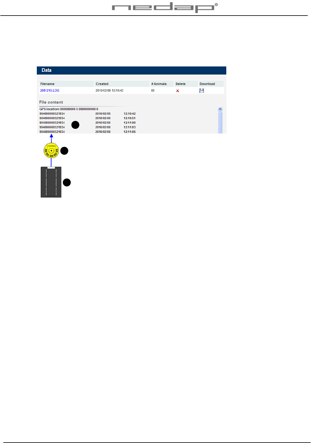
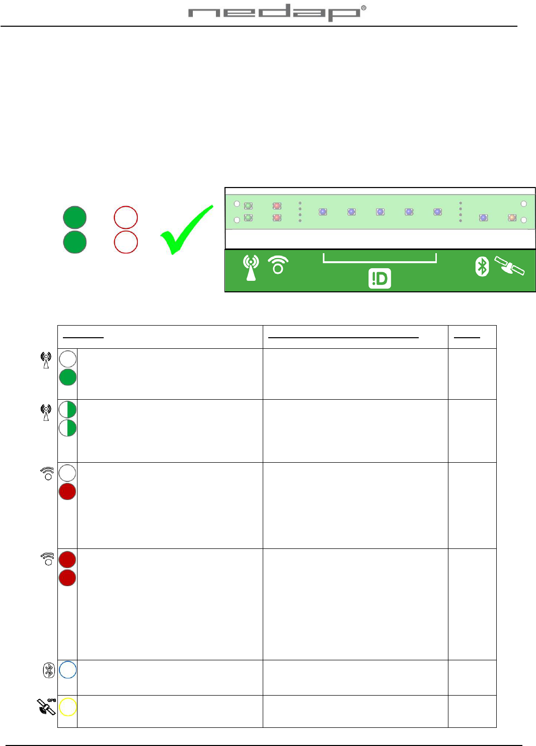
Check the operation of the VP1850 Panel reader regularly with (a few) tag(s). Check the actual
state of the Panel reader. The Panel reader led lights will show if there are any malfunctions.
The Panel reader led lights will show if the system is working correctly or not.
Green
light
Red
light
Both
ON
+ Both
OFF
= OK
Display VP1850 Panel reader
Check the cause of the malfunction and solve it.
Problem What/How to check or re-install See §
1 green light on: reduced antenna field
caused by some iron. Identification
possible but reduced performance.
Antenna tuning. Remove the iron from
the Panel reader area.
2 flashing green lights: no correct
antenna field caused by a lot of iron.
Identification possible but a very much
reduced performance.
Antenna tuning. Remove the iron from
the Panel reader area.
1 red light(s) on: identification possible
but reduced performance caused by
electrical equipment with background
noise. Possibly cable or power supply /
transformer < 1.5 m. from the Panel
reader.
Find source of the background noise in
the Panel reader area that disturbs the
antenna e.g. a power supply,
fluorescent lightning, another antenna
or a frequency controller. Delete it or
turn it off.
2
2 red light(s) on: strongly reduced
performance caused by a no
synchronisation with a nearby HDX
reader or electrical equipment with
strong electrical background noise.
Possibly cable or power supply /
transformer < 1.5 m. from the Panel
reader. No identification possible.
Find source of the background noise in
the Panel reader area that disturbs the
antenna e.g. a power supply,
fluorescent lightning, another antenna
or a frequency controller. Delete it or
turn it off. Install cables and power
supply / transformer > 1.5 m. from the
Panel reader if possible.
2
Blue light not on: no signal or blue
tooth pincode not entered correctly.
Check the pin code. 3.3
Yellow light not on: no GPS signal in
the area or building.
If indoors move Panel reader outdoors.
If outdoors no GPS signal available.
VP1850-200PM-00GB-Panel reader Manual version 1.2 / Page 10
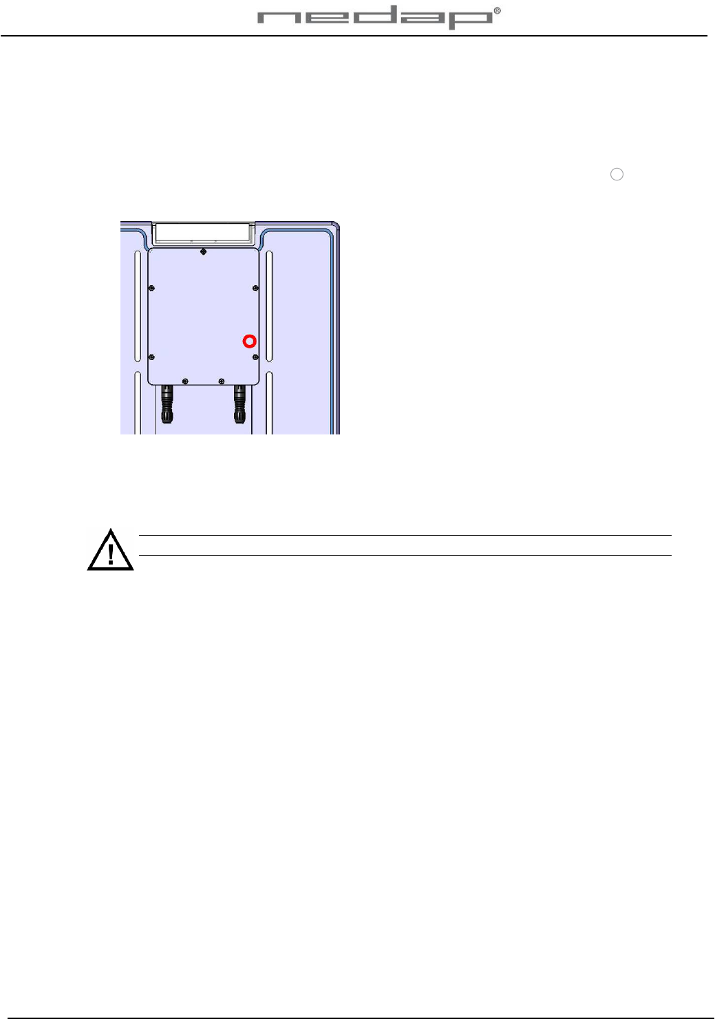
5.2. Resetting the VP1850 Panel reader
If necessary set the VP1850 Panel reader back to its factory defaults:
1. Turn on the power
2. Put a magnet on the spot indicated on the back of the Panel reader with a circle on the
sticker and keep it there. A row of blue leds will light up when the magnet is in the correct
position.
3. Turn off the power and turn it back on. The row of blue leds will light up again.
4. Remove the magnet from the Panel reader.
5. Turn off the power and turn it back on again.
The Panel reader is now set back to its factory defaults.
The IP address now is 10.10.10.10 again like in the beginning.
See chapter 3 to start up the operation again by setting the network configuration and the
software settings.

VP1850-200PM-00GB-Panel reader Manual version 1.2 / Page 11
6. Maintenance and disposal
6.1. Maintenance
Check the operation of the VP1850 Panel reader regularly.
No regular maintenance is required.
The Panel reader can be cleaned with water and sponge. Avoid (aggressive) cleaning liquids.
6.2. Disposal
At discard dispose of materials from the Panel reader in accordance with the current
environmental rules of the state or local governing authorities.
VP1850-200PM-00GB-Panel reader Manual version 1.2 / Page 12
Appendix A Technical specifications
Measurements VP1850 Panel reader
Total height 595 mm
Total width 395 mm
Depth 30 mm
Specifications for transport / installation
Weight VP1850 Panel reader 6.2 kg
Electrical supply
Main supply 100V - 240V
Frequency 50 – 60 Hz
Input voltage (use Nedap power supply) 12 – 48 V DC
Input current (mA) depends on input voltage (without buzzer) 1 – 0.5 A
Environmental
Operating temperatures - 10°C / + 45°C
Transport / storage temperatures - 40°C / + 70°C
Humidity (rh) 45°C / 85%
Enclosure protection class (when cover and cables installed correctly) IP67
The Panel reader may not be exposed to direct sunlight.
The Panel reader must always be transported and stored dry and frost-free.
VP1850-200PM-00GB-Panel reader Manual version 1.2 / Page 13
Appendix B Wiring Panel reader
Wiring scheme Panel reader cable 1.
Connector number Velos Panel reader cable ( art.nr.7707029)
1 Red + (12 – 48 V)
2 Black -
3 Blue Tx+ Ethernet 10 Mb Tx+
4 Blue / White Tx- Ethernet 10 Mb Tx-
Shield Shielding
5 Orange Rx+ Ethernet 10 Mb Rx+
6 Orange / White Rx- Ethernet 10 Mb Rx-
7 Green TxD RS232 TxD
8 Green / White RxD RS232 RxD
Wiring scheme Panel reader cable 2.
Connector number Velos Panel reader cable ( art.nr.7707029)
1 Red Not connected
2 Black - Minus
3 Blue FDX in F-synchronization FDX in
4 Blue / White FDX out F-synchronization FDX out
Shield Shielding
5 Orange HDX HDX synchronization
6 Orange / White HDX HDX synchronization
7 Green Output Buzzer -
8 Green / White Output Buzzer + (10 - 24 V)
1 2
VP1850-200PM-00GB-Panel reader Manual version 1.2 / Page 14
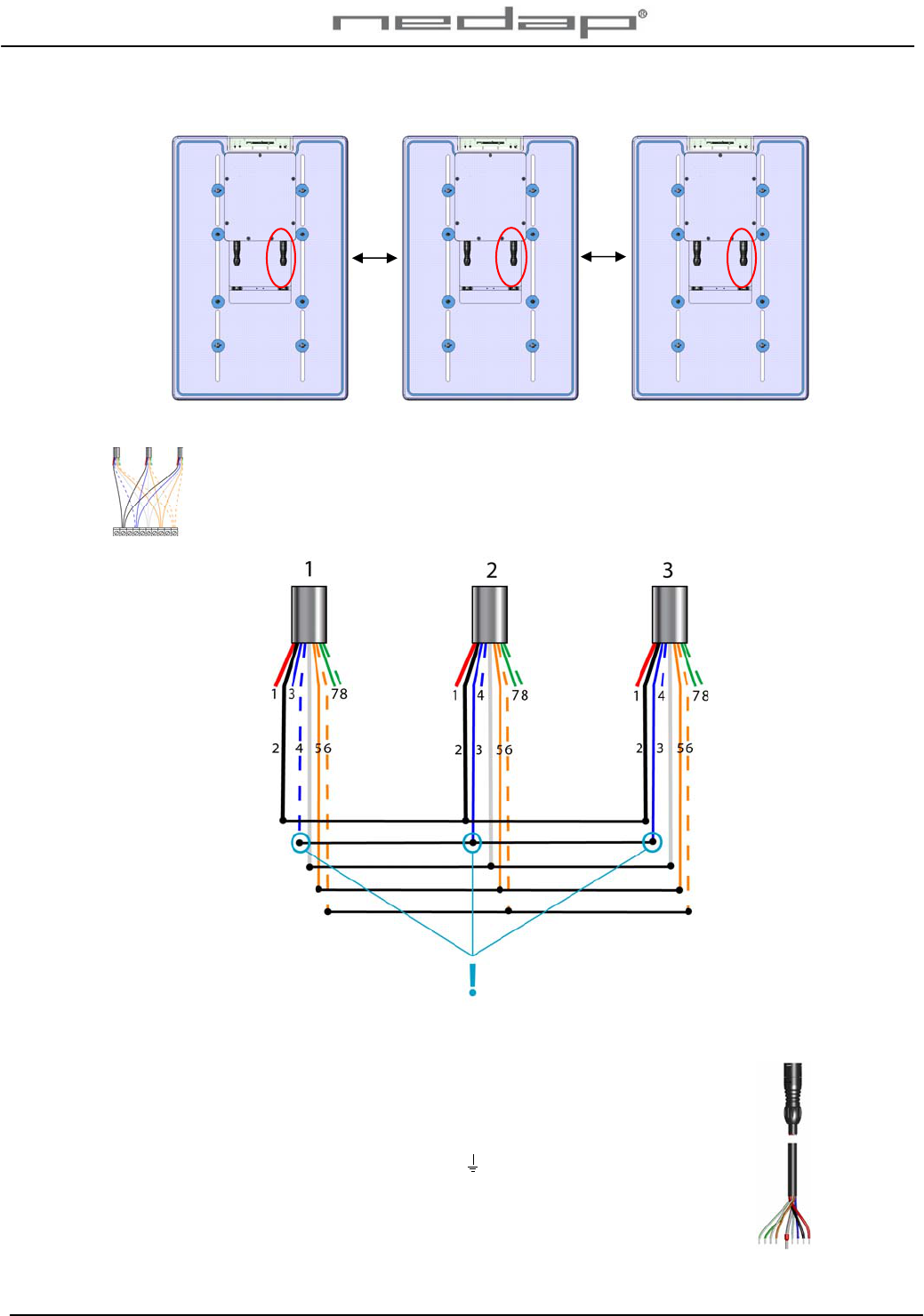
Wiring more than one Panel reader.
1 2 3
Connect all cables with number 2 to a Connector block. Connect the 1st blue-white
wire and the 2nd and 3rd blue wires to one connector point. Connect all 3 black,
shielding, orange and orange-white wires, each colour to one connector block point.
Wiring scheme Panel reader cable 2.
Connector number Velos Panel reader cable ( art.nr.7707029)
1 Red Not connected
2 Black - Minus
3 Blue FDX in F-synchronization FDX in
4 Blue / White FDX out F-synchronization FDX out
Shield Shielding
5 Orange HDX HDX synchronization
6 Orange / White HDX HDX synchronization
7 Green Output Buzzer -
8 Green / White Output Buzzer + (10 - 24 V)
2 >2m 2 >2m 2
VP1850-200PM-00GB-Panel reader Manual version 1.2 / Page 15
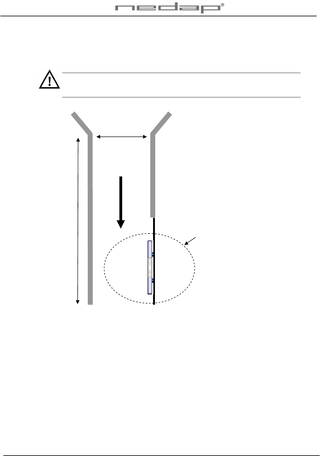
Appendix C Corridor requirements
The maximum corridor width at the Panel reader location will be different for each animal sort
and breed. Make sure the corridor is not too wide at the Panel reader location.
The maximum width of the corridor is essential to achieve a proper working system.
Animals should never be able to pass each other, turn around or walk in the wrong
direction.
IN
The identification distance of the
antenna field
Maximum corridor entrance width:
Allow passage of 1 animal at the
time. Keep the corridor as narrow
as possible.
RFID Eartags : Attach all ear tags
on same side of animals (left in
this example).
The antenna must be mounted at
the side where the tag is
attached.
The identification distance of the
antenna varies per installation. It
depends on the iron and the
background noise in the panel
reader area.
Maximum width
1 animal wide
Minimum length 1 animal long

VP1850-200PM-00GB-Panel reader Manual version 1.2 / Page 16