Nedap N V VP4102 VP4102 User Manual VP1001
N. V. Nederlandsche Apparatenfabriek NEDAP VP4102 VP1001
14r01_9741518 Quick start VP4102 CGDVP4102
VP4102 – Reader - Quick start 05-2013 Doc.part.no. 9741518 version 1.0 1/ 5
VP4102 Reader 434/922 MHz
This sheet is intended as quick start. See service manual for more detailed instructions.
The VP4102 reader is a component that is used to receive data from Smart Tags.
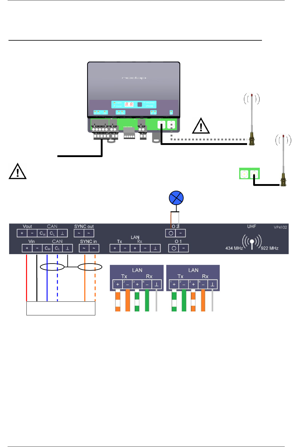
Antenna default connection is 434MHz. Japan and Korea: switch to 922MHz!
Connections
Compliance statement (part15.19)
This device complies with part 15 of the FCC Rules and to RSS210 of Industry Canada.
Operation is subject to the following two conditions:
(1) this device may not cause harmful interference, and
(2) this device must accept any interference received, including interference that may cause undesired operation.
Déclaration Conformité
Cet appareil se conforme aux normes RSS210 exemptés de license du Industry Canada. L'opération est soumis aux deux
conditions suivantes:
(1) cet appareil ne doit causer aucune interférence, et
(2) cet appareil doit accepter n'importe quelle interférence, y inclus interférence qui peut causer une opération non pas voulu de
cet appareil.
Warning (part15.21)
Changes or modifications not expressly approved by party responsible for compliance could void the user’s authority to operate
the equipment. This in particular is applicable for the antenna which can be delivered with the VP4102 System
orange
blue white
blue
black
red
orange white
CAN cable
LAN Ethernet straight cable
white
brown
or
VP4102
CAN cable to VPU (VP8001)
Antenna
922 MHz
Antenna
434 MHz
TIA/EIA 568A TIA/EIA 568B
VP4102 – Reader - Quick start 05-2013 Doc.part.no. 9741518 version 1.0 2/ 5
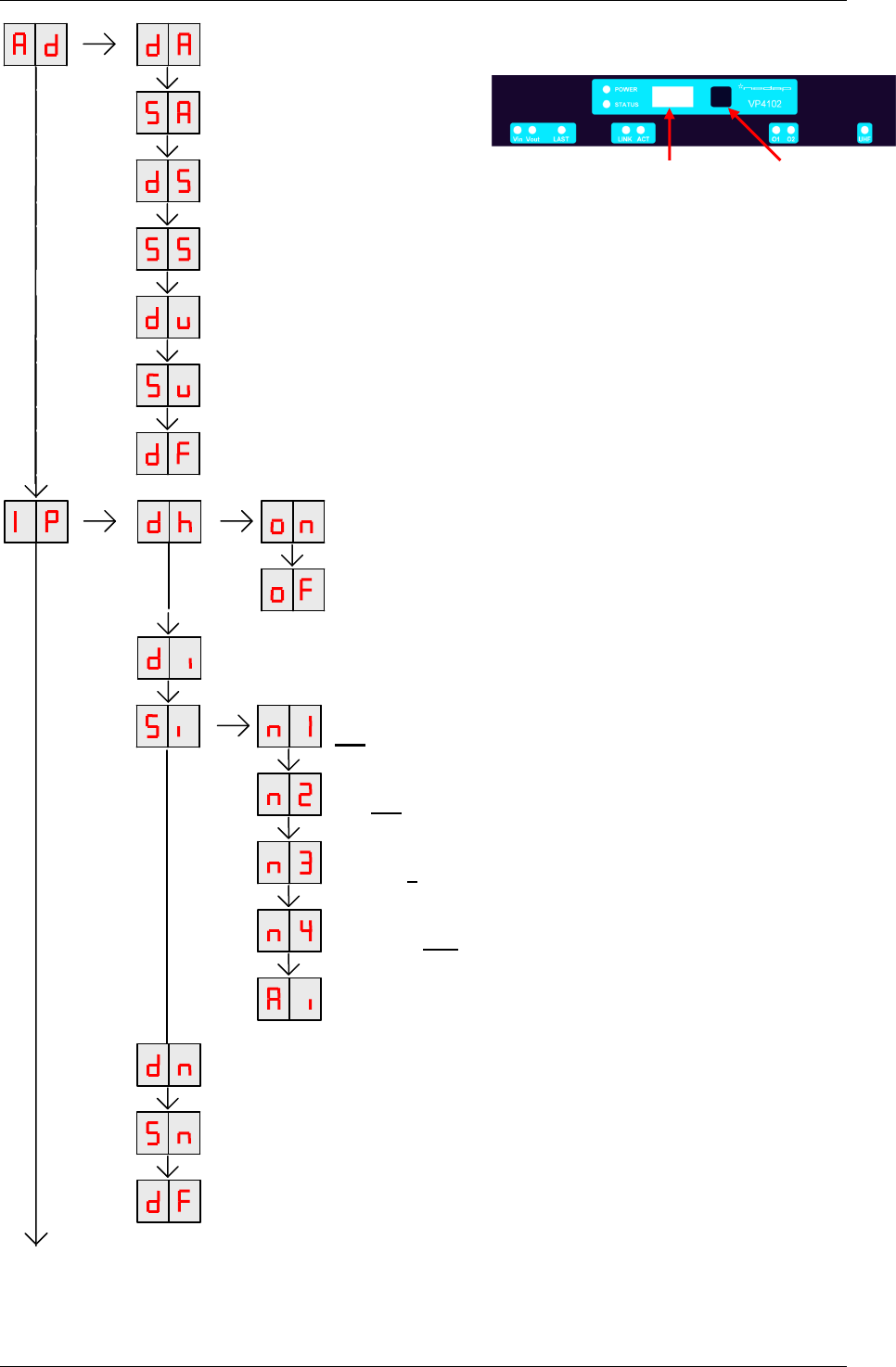
DISPLAY ADDRESS
Shows the actual logic V-pack address
SET ADDRESS
Change the logic address
DISPLAY SECTION
Show section (Default 0, not used for CAN)
SET SECTION
Change section (not used for CAN)
DISPLAY VPU ADDRESS
Shows actual VPU address (one by one)
SET VPU ADDRESS
Changes the actual VPU address (one by one)
SETTINGS TO DEFAULT
All address settings back to factory settings
DHCP IS ON
Press long until blinking to turn on DHCP
DHCP IS OFF
Press long until blinking to turn off DHCP
DISPLAY IP ADDRESS
Shows actual IP address (one by one)
SET IP ADDRESS (only shown in case of DHCP OFF)
192.168.1.101 (not used for CAN)
SET IP ADDRESS
192.168.1.101 (not used for CAN)
SET IP ADDRESS
192.168.1.101 (not used for CAN)
SET IP ADDRESS
192.168.1.101 (not used for CAN)
ACCEPT NEW IP ADDRESS
(not used for CAN)
DISPLAY NETWORK MASK (only shown in case of DHCP OFF)
Shows the network mask (0, 8, 16, 24 or 32) (0= 0.0.0.0, 8= 255.0.0.0 etc.)
SET NETWORK MASK (only shown in case of DHCP OFF)
Changes the network mask (16= 255.255.0.0 etc. 32 = 255.255.255.255)
IP SETTINGS TO DEFAULT
All IP settings back to factory settings
Display Push button
VP4102 – Reader - Quick start 05-2013 Doc.part.no. 9741518 version 1.0 3/ 5
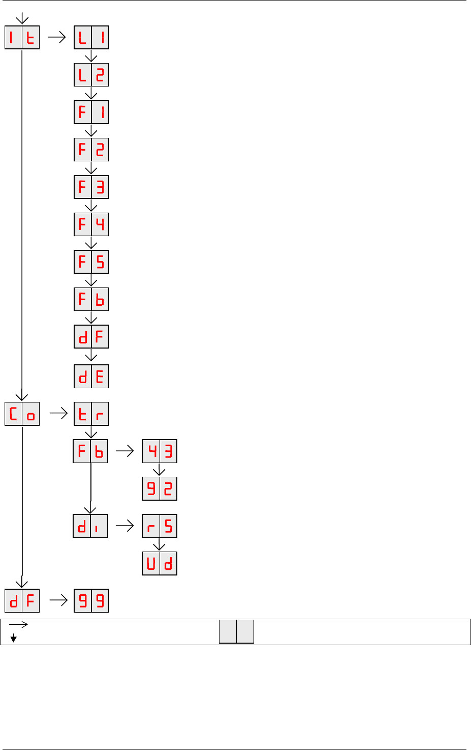
Press button until blinking
Press button short
To leave menu:
press button until display is empty
L1 TEST OUTPUT 1
Signal light
TEST OUTPUT 2
Signal light
TEST FREQUENCY 1
Shows signal strength frequency 1
TEST FREQUENCY 2
Shows signal strength frequency 2
TEST FREQUENCY 3
Shows signal strength frequency 3
TEST FREQUENCY 4
Shows signal strength frequency 4
TEST FREQUENCY 5
Shows signal strength frequency 5
TEST FREQUENCY 6
Shows signal strength frequency 6
RESET UHF CHANNELS SETTINGS TO DEFAULT
All UHF channel settings back to factory settings
DISPLAY ERROR
SE = safeguard error, UE = UHF error.
TRESHOLD RECEPTION (CONFIGURATION MENU)
Enter value to set UHF threshold e.g. …?
FREQUENCY BAND 434MHz (EU/USA)
Press long until blinking to switch to 434Mhz
FREQUENCY BAND 922MHz (Japan/Korea only)
Press long until blinking to switch to 922Mhz
DISPLAYS RSSI STRENGTH OF LAST UHF MESSAGE
View last received RSSI
DISPLAYS NUMBER OF DETECTED UHF DEVICES
(only when UHF network is enabled)
RESTORE FACTORY DEFAULTS
All VP4102 settings back to factory defaults (Default IP address)
VP4102 – Reader - Quick start 05-2013 Doc.part.no. 9741518 version 1.0 4/ 5
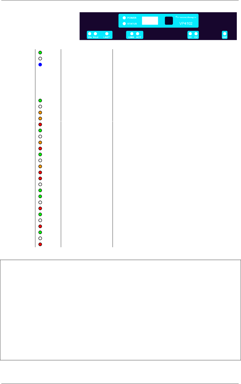
LED indicators
POWER
Green on
Power on
off
No power
STATUS
Slow blinking
Fast blinking
1 short flash
2 short flashes
3 short flashes
Operating ok
Downloading or error during download
V-pack not coupled
Firmware present but not active
No firmware present
Display
Blinking
IP fails or CAN fails
V in
Green on
Input power applied
off
No power
Orange
Low power, less than 20V
Orange blinking
Wrong CAN-bus connection, Vin and Vout swapped
Red
Error, plus and minus swapped
V out
Green on
Output power
off
No power
Orange blinking
Low power
Red blinking
Error (overload, shortcut)
LAST
Green on
V-pack is last one on the CAN-bus
off
V-pack is not last one on the CAN-bus
Orange blinking
CAN-bus error and last V-pack on CAN-bus
Red
CAN-bus error
Red blinking
CAN-bus warning / connected wrong
LINK
off
LAN No connection
Green
LAN connection(10 Mbps / 100 Mbps)
ACT
Green flashing
Network activity
off
No network activity
Red
Network error
O1 / O2
Green on
Output on
off
Output off
Red blinking
Output error (overload, shortcut)
UHF
Green on
Data receive
off
No data
Red
UHF Error
Specifications VP 4102
Dimensions
143 x 120 x 68 mm LxWxH (excluding mounting rail) Weight: ± 279 gr
CAN
CAN-bus communication 125 kbit/s
Ethernet
100mbit/s max 100m
Power
Input voltage 12VDC -30 VDC
Power consumption 160mA – 85mA (25VDC 100 mA) (without connected I/O such as
signal lamp)
Protected against reverse connection power supply
Software
Downloadable by the CAN network or ethernet
Outputs
Max. 0.4 Amp by current limiter, short-circuiting and thermal protected
Antennas
G-CXL 70-1LW/h nedap art. 4602366
Detection distance
Lactivator Realtime labels: +/- 50m dependable of antenna situation
Environment
Temperature: Operating: -10 – 55 °C, Storage: -25 – 70 °C
Relative humidity: 10 – 93% non condensing
IP class
IP 30. When installed in V-box IP 65 (cover and cables installed correctly !)
Always use a NEDAP power supply VP2001 or VP2002. The Nedap guarantee-regulations are only valid when is
installed as indicated in this manual. Install data cables at a safe distance from (high) powered cables
For more detailed information contact your local Nedap supplier or check the internet site.
VP4102 – Reader - Quick start 05-2013 Doc.part.no. 9741518 version 1.0 4/ 5
LED indicators
POWER
Green on
Power on
off
No power
STATUS
Slow blinking
Fast blinking
1 short flash
2 short flashes
3 short flashes
Operating ok
Downloading or error during download
V-pack not coupled
Firmware present but not active
No firmware present
Display
Blinking
IP fails or CAN fails
V in
Green on
Input power applied
off
No power
Orange
Low power, less than 20V
Orange blinking
Wrong CAN-bus connection, Vin and Vout swapped
Red
Error, plus and minus swapped
V out
Green on
Output power
off
No power
Orange blinking
Low power
Red blinking
Error (overload, shortcut)
LAST
Green on
V-pack is last one on the CAN-bus
off
V-pack is not last one on the CAN-bus
Orange blinking
CAN-bus error and last V-pack on CAN-bus
Red
CAN-bus error
Red blinking
CAN-bus warning / connected wrong
LINK
off
LAN No connection
Green
LAN connection(10 Mbps / 100 Mbps)
ACT
Green flashing
Network activity
off
No network activity
Red
Network error
O1 / O2
Green on
Output on
off
Output off
Red blinking
Output error (overload, shortcut)
UHF
Green on
Data receive
off
No data
Red
UHF Error
Specifications VP 4102
Dimensions
143 x 120 x 68 mm LxWxH (excluding mounting rail) Weight: ± 279 gr
CAN
CAN-bus communication 125 kbit/s
Ethernet
100mbit/s max 100m
Power
Input voltage 12VDC -30 VDC
Power consumption 160mA – 85mA (25VDC 100 mA) (without connected I/O such as
signal lamp)
Protected against reverse connection power supply
Software
Downloadable by the CAN network or ethernet
Outputs
Max. 0.4 Amp by current limiter, short-circuiting and thermal protected
Antennas
G-CXL 70-1LW/h nedap art. 4602366
Detection distance
Lactivator Realtime labels: +/- 50m dependable of antenna situation
Environment
Temperature: Operating: -10 – 55 °C, Storage: -25 – 70 °C
Relative humidity: 10 – 93% non condensing
IP class
IP 30. When installed in V-box IP 65 (cover and cables installed correctly !)
Always use a NEDAP power supply VP2001 or VP2002. The Nedap guarantee-regulations are only valid when is
installed as indicated in this manual. Install data cables at a safe distance from (high) powered cables
For more detailed information contact your local Nedap supplier or check the internet site.
Under Industry Canada regulations, this radio transmitter may only operate using an antenna of a type and maximum (or lesser)
gain approved for the transmitter by Industry Canada. To reduce potential radio interference to other users, the antenna type and
its gain should be so chosen that the equivalent isotropically radiated power (e.i.r.p.) is not more than that necessary for successful
communication.
This radio transmitter with certification number 1444A-VP4102 has been approved by Industry Canada to operate with the antenna
type listed below and with the maximum permissible gain and required antenna impedance indicated. Antenna types not included
in this list, having a gain greater than the maximum gain indicated for that type, are strictly prohibited for use with this device.
Model: G-CXL 70-1LW/h (nedap art. 4602366)
Antenna gain: 2 dBi
Nominal impedance: 50 Ω