Nedap N V XQ Anti Pilferage system User Manual NCC4 v2 10
N. V. Nederlandsche Apparatenfabriek NEDAP Anti Pilferage system NCC4 v2 10
user manual

Date: 5 October 2004 Version 2.10
This information is furnished for guidance, and with no guarantee as to its accuracy or completeness; its publication conveys no license under any patent or other right, nor does
the publisher assume liability for any consequence of its use; specifications and availability of goods mentioned in it are subject to change without notice; it is not to be
reproduced in any way, in whole or in part, without the written consent of the publisher.
_________________________________________________________________________________________________________
© Nedap Retail Support P.O. Box 102 NL-7140 AC Groenlo the Netherlands
NCC4

2
© Nedap Retail Support 2004 – Groenlo Holland
NCC4 2.10 10.5.2004 GO
Support H. Hammer H. Broekhuis
+31 (0) 544 47 15 55 +31 (0) 544 47 15 19 +31 (0) 544 47 15 02
support-rs@nedap.com hans.hammer@nedap.com han.broekhuis@nedap.com
Visitor’s address Postal address: Fax
Nedap Retail Support
Parallelweg 2d
Groenlo
Netherlands
Nedap Retail Support
Postbus 102
7140 AC Groenlo
+31 (0) 544 46 58 14
© 2004 Nedap Retail Support - Netherlands
Parallelweg 2d, 7141 DC Groenlo
The software / hardware described in this book / file is furnished under a license agreement and may be used only in accordance with the terms of
the agreement.
Documentation version 2.10
Copyright Notice
All Rights Reserved.
Any technical documentation that is made available by Nedap Retail Support is the copyrighted work of Nedap Retail Support and is owned by Nedap
Retail Support.
NO WARRANTY. The technical documentation is being delivered to you and Nedap Retail Support makes no warranty as to its accuracy or use. Any
use of the technical documentation or the information contained therein is at the risk of the user.
Documentation may include technical or other inaccuracies or typographical errors.
Nedap Retail Support reserves the right to make changes without prior notice.
No part of this publication may be copied without the express written permission of Nedap Retail Support, Parallelweg 2d, 7141 DC Groenlo,
Netherlands.
Trademarks
Nedap, the Nedap logo, Nedap EASi/Net and the Nedap EASi/Net are registered trademarks of Nedap N.V. Groenlo.
Other product names mentioned in this manual may be trademarks or registered trademarks of their respective companies and are hereby
acknowledged.
Printed in the Netherlands
Technical Support:

3
© Nedap Retail Support 2004 – Groenlo Holland
NCC4 2.10 10.5.2004 GO
Postal address: 2
Fax 2
DC power supply 5
HF 5
Data-com 5
RS 232 interface 5
I/O connector 5
Hand-terminal connector 5
The following points can be used 6
Indicator leds 6
Testpoints 6
Specifications 7
Revison-view: 8
Table of content
4
© Nedap Retail Support 2004 – Groenlo Holland
NCC4 2.10 10.5.2004 GO
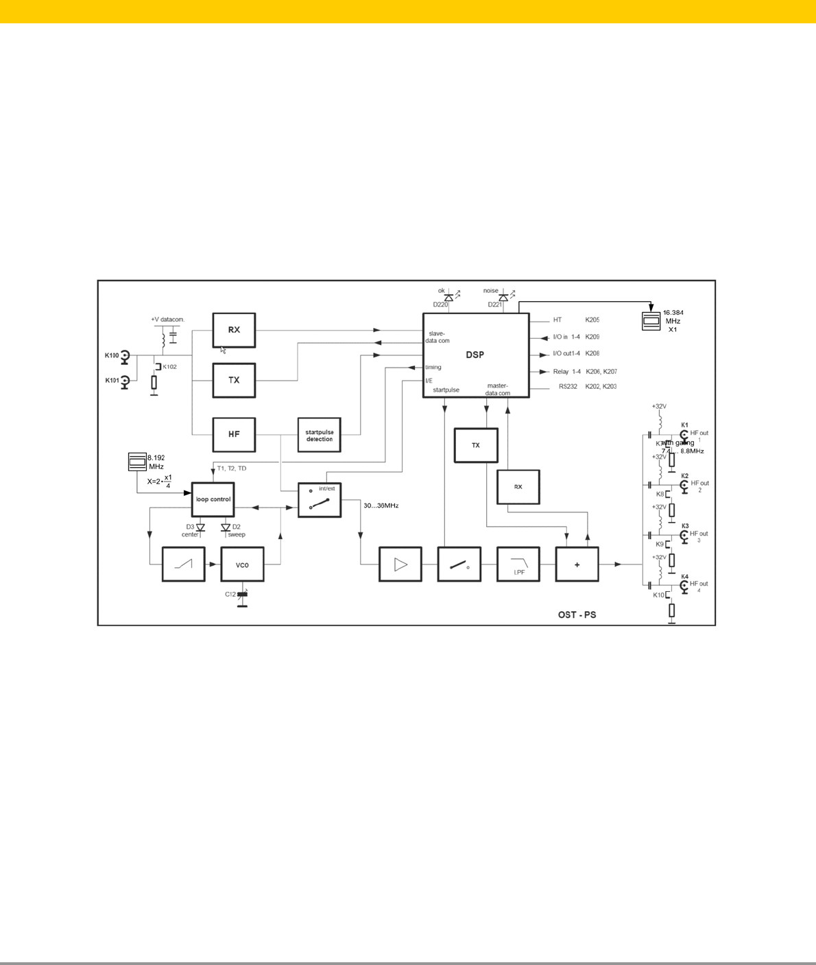
The Network Communication & Control unit (NCC4) in the OS/T has several functions:
• Supplying the 33V DC power supply for all the units in the system. On 1 NCC4 it’s possible to
connect up to 16 receiver (NR4) or transmitters (NT4) units.
• Generating the HF sync signal for the whole system. This HF signal has a frequency of four times
8.2 MHz and sweeps between 30.... 36 MHz. One NCC4 has four outputs and on each output you
can connect a NR4, NT4 or an other NCC4.
• The NCC4 is data-com master for all connected units. All data-communication between the
connected units and the NCC4 will be initiated from the NCC4. With the external sync input from the
NCC4 it’s possible to integrate the NCC4 in a larger network with multiple NCC4's.
• Each NCC4 has a RS 232 communication connector from which it’s possible to connect to the
outside world, for example to a modem or to a PC. With this connection several things can be done,
such as remote-diagnostics and firmware-upgrades.
Figure 1 shows the block diagram of the OS/T NCC4.
Fig.1
OS/T Network Communication & Control unit

5
© Nedap Retail Support 2004 – Groenlo Holland
NCC4 2.10 10.5.2004 GO
DC power supply
The 33 Volt DC Power voltage from the OS/T system is generated in a Switched-mode power unit,
which is connected with a short cable on connector K5. The power supply has a continuous DC output
current rating of 3.2 A.
HF
The HF signal is generated in a VCO. This VCO uses for its frequency control the 3 signals from the
local DSP: TD, in advance of the start pulse and T1 and T2 on 345 and 1334 s after the start pulse.
The signals T1 and T2 mark the time that the frequency of the NT4 passes the 7.7 and 8.7 MHz. A
saw-tooth generator generates the waveform, necessary to sweep the VCO. The saw-tooth generator
exists of a capacitor, charged with a constant current and is discharged at every pulse.
Regulation of the VCO happens only in the fly-back period to get the highest possible signal purity. By
using a buffer stage the HF-signal gets the requested level and will be merged with the data-com
signal. Then this signal is distributed to four output connectors K1 till K4.
Data-com
One of the important features from the OS/T system is the data-com over the coax-cable. With this
feature it’s no longer necessary to use an extra data-cable between the units, which simplify the
installation of the system. The NCC4 plays a central roll in providing the data-com. All the connected
units are interrogated periodically by the NCC4. If there are messages like an alarm on a connected
NR4, then the NCC4 will be process this and takes the necessary action: Sending a command, to turn
on the lamps on the activated aisle.
At the beginning of each sweep, on a fixed timeslot, the NCC4 sends a data-block. This data-block
may contain a question for a connected NR4 or NT4. The answer will be transmitted in another time-
slot.
The transmission of data is accomplished by adding small pulses on the HF signal. With a low pass
filter and a sensitive amplifier these pulses can be recovered on the receiving side..
If multiple NCC4's are necessary to be fitted in a larger installation, then they have to be linked. Every
NCC4 is then a master for his own segment. The “upper neighbour” of a NCC4 is connected to a slave
sync input, while the “under neighbour” in the circuit will be connected on an output. The slave sync
input is doubled to link the incoming cable to the next segment of the “upper neighbour”. When the
NCC4 is the last one in a chain a terminator jumper must be placed.
A slave NCC4 may be switched off without disturbing the data communication.
RS 232 interface
Each NCC4 is equipped with a RS232 connector. With this it’s possible to connect a modem or a PC
to communicate with the OS/T system.
With these capabilities you can use remote-diagnostics, firmware-upgrade and system configuration.
The communication uses the standard UART circuit.
I/O connector
The NCC4 comes with an I/O connector with four opto-coupler inputs, four opto-coupler outputs and
four relay outputs with one voltage free make-and-break contact. All in- and outputs are galvanic
separated from the power supply. The in- and outputs may be used for camera activation, metal
detection alarm, extra alarm-lamps. The functionality of the in- and outputs is determined by the
software.
Hand-terminal connector
A standard NEDAP RS Handheld terminal may be connected to the NCC4. With these HT you can
edit the various local settings.
Description of the NCC4:
6
© Nedap Retail Support 2004 – Groenlo Holland
NCC4 2.10 10.5.2004 GO
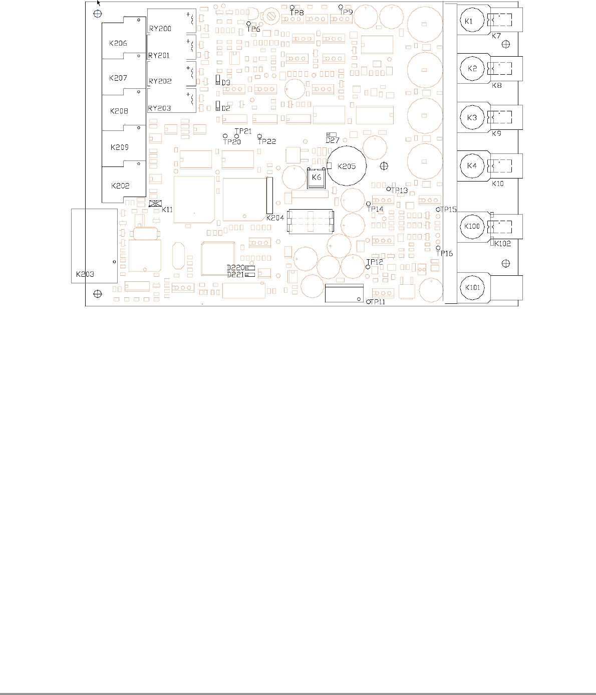
Figure 2 shows the component arrangement of the NCC4 (Hardware version 4):
The following points can be used
K100 slave sync input K10 50 ohm terminator in aid of K4
K101 slave sync input K11 50 ohm terminator in aid of K202
K102 50 ohm terminator K202 RS 485 interface connector
K1 Output K203 RS 232 interface connector
K2 Output K205 Hand-terminal connection
K3 Output K206 Relay outputs Ry3, Ry4
K4 Output K207 Relay outputs Ry1, Ry2
K5 32V DC power input K208 Opto outputs 1-4
K6 power LED connection K209 Opto inputs 1-4
K7 50 ohm terminator in aid of K1 C12 VCO linearity
K8 50 ohm terminator in aid of K2
K9 50 ohm terminator in aid of K3
Indicator leds ( Y = yellow, Rd = red, Gr = green)
D27 Power (Gr)
D220 NCC4 (Y) (On= a tag is detected by the NR4)
D221 NCC4 comm fault (Rd) (On= a segment doesn’t answer)
D2 Sweep lock(Y)
D3 Center lock(Y)
Testpoints
Tp6 Sweep voltage Tp11 Slave Tx
Tp7 Master Tx Tp12 Slave Rx
Tp8 Master Rx Tp13 Slave Start
Tp9 Master Clk Tp20 T2
Tp15 Slave Clk Tp21 T1
Tp16 Slave HF in Tp22 TD
Tp14 Slave HF 32MHz

7
© Nedap Retail Support 2004 – Groenlo Holland
NCC4 2.10 10.5.2004 GO
Specifications
Mains NCC4:
Power Supply 230 Volt 50 Hz (90-220 Volt 50-60 Hz)
Power Consumption Max 150 Watt
NCC4-pcb:
Power supply 33 Volt DC
Current consumption 100 mA (excl connected slave units)
Sync input signal 30-36 MHz, minimal 4 dB in 50 ohm (1Vtt)
Outputs (4x) 30-36 MHz, nominal 10 dB in 50 ohm (2Vtt)
Frequency sweep 1400 kHz
Sweep frequency 600 Hz saw tooth form.
Maximal DC load to one or more outputs 3.2 A (ca 16 slave units)at 230 V
Maximal DC load to one or more outputs 2.0 A (ca 10 slave units)at 115 V
8
© Nedap Retail Support 2004 – Groenlo Holland
NCC4 2.10 10.5.2004 GO
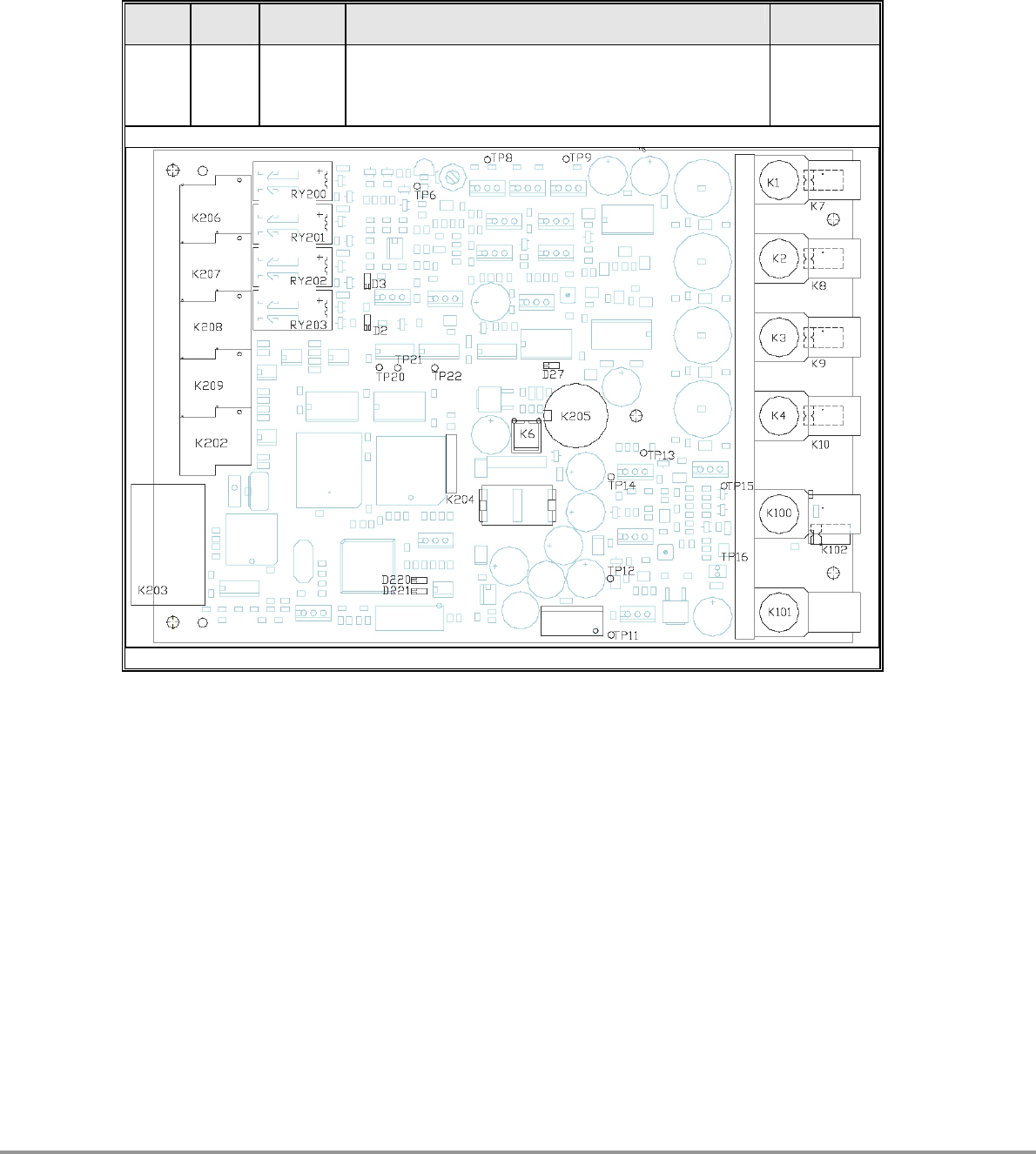
Revison-view:
Hardware version 5:
Nr Index
Date Description Perform
april
2000 - Jumper K11 removed and K202 became a feature
connector.
- Jumper K102 moved a little.
- Components are removed / changed.
Nedap