Nelson Irrigation VRCOMM-HP VRS (TWIG) User Manual RF Installation Manualx
Nelson Irrigation Corporation VRS (TWIG) RF Installation Manualx
Contents
- 1. User Manual 1
- 2. User Manual 2
User Manual 2
VRS(TWIG)InstallationManual
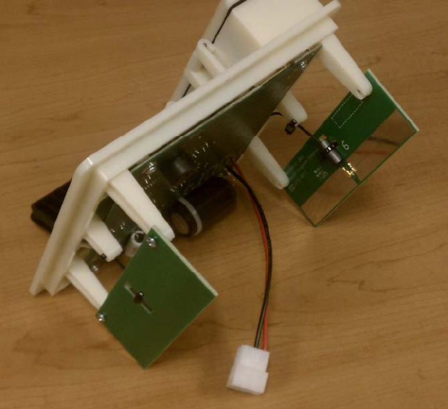
1.VRS(TWIG)modulewith(singleordual)internallymountedantenna
a)Connectoneendofa200mmUMCCcable(TEConnectivityModel#2015357‐4200mm
UMCCplug‐UMCCplug)toaNelsondipoleantenna.
b)Slideferritebead(Laird‐SignalIntegrityProducts#28B0275‐00)overtheUMCCcable.Secure
ferritebeadtoantennaPCB.
c)ConnecttheoppositeendoftheUMCCcabletoJ1oftheLSRmodule.
d)Repeatstepsa)andb)fordualantennamodel.ConnecttheoppositeendoftheUMCCcable
toJ2oftheLSRmodule.
e)MountVRS(TWIG)PCBandantennasonplasticsubassemblyframeasshowninfigure1
below.
Figure1
2.VRS(TWIG)modulewithexternallymountedantenna
a)ConnectU.FL.endof200mmU.FLtoRPSMAcable(L‐ComModel#CA‐UFLRSBQC20U.FLto
RP‐SMACable,20cm1.13SeriesMiniCoax(50ohm))toLSRmodule.
b)FastenRPSMAbulkheadendtoVRS(TWIG)modulehousing
c)ConnectatleastthreefeetofLRM‐195coaxcablewithRPSMAconnectortotheRPSMA
bulkheadandtheoppositeendtoanN‐typemaleconnector
d)ConnecttheN‐typemaleconnectortoeitheranL‐ComModel#HGV‐906VOmnihaving6dBi
gainoraComtelcoModel#Y3387Yagihaving10.2dBdgain.
3.VRS(TWIG)gatewaywithexternallymountedantenna
a)ConnectU.FL.endof200mmU.FLtoRPSMAcable(L‐ComModel#CA‐UFLRSBQC20U.FLto
RP‐SMACable,20cm1.13SeriesMiniCoax(50ohm))toLSRmodule.
b)FastenRPSMAbulkheadendtothegatewayenclosure.
c)ConnectatleastthreefeetofLRM‐195coaxcablewithRPSMAconnectortotheRPSMA
bulkheadandtheoppositeendtoanN‐typemaleconnector
d)ConnecttheN‐typemaleconnectortoeitheranL‐ComModel#HGV‐906VOmnihaving6dBi
gainoraComtelcoModel#Y3387Yagihaving10.2dBdgain.
Federal Communication Commission Interference Statement
This equipment has been tested and found to comply with the limits for a Class B digital device, pursuant to
Part 15 of the FCC Rules. These limits are designed to provide reasonable protection against harmful
interference in a residential installation. This equipment generates uses and can radiate radio frequency
energy and, if not installed and used in accordance with the instructions, may cause harmful interference
to radio communications. However, there is no guarantee that interference will not occur in a particular
installation.
If this equipment does cause harmful interference to radio or television reception, which can be
determined by turning the equipment off and on, the user is encouraged to try to correct the interference
by one of the following measures:
- Reorient or relocate the receiving antenna.
- Increase the separation between the equipment and receiver.
- Connect the equipment into an outlet on a circuit different from that to which the receiver is
connected.
- Consult the dealer or an experienced radio/TV technician for help.
This device complies with Part 15 of the FCC Rules. Operation is subject to the following two conditions: (1)
This device may not cause harmful interference, and (2) this device must accept any interference
received, including interference that may cause undesired operation.
FCC Caution: Any changes or modifications not expressly approved by the party responsible for
compliance could void the user's authority to operate this equipment.
INDUSTRY CANADA STATEMENTS
Operation is subject to the following two conditions: (1) this device may not cause interference, and (2) this
device must accept any interference, including interference that may cause undesired operation of the
device. To reduce potential radio interference to other users, the antenna type and its gain should be so
chosen that the equivalent isotropically radiated power (e.i.r.p.) is not more than that permitted for
successful communication. This device has been designed to operate with the antennas listed below, and
having a maximum gain of 10.2 dBd. Antennas not included in this list or having a gain greater than 10.2
dBd are strictly prohibited for use with this device. The required antenna impedance is 50 ohms.
Approved antenna list:
- Nelson VRS PCB dipole antenna
- L-Com Model #HGV-906V Omni 6dBi gain
- Comtelco Model #Y3387 Yagi 10.2dBd gain.
“To comply with FCC and Industry Canada RF radiation exposure limits for general population, the
antenna(s) used for this transmitter must be installed such that a minimum separation distance of 20cm is
maintained between the radiator (antenna) and all persons at all times and must not be co-located or
operating in conjunction with any other antenna or transmitter.”
“Contains Transmitter Module FCC ID: TFB-SIFLEX2HP IC: 5969A-SIFLEX2HP”