Neology RDR8018 Long-Range RFID Reader User Manual Installation Operation Manual 007 04 A
Neology Long-Range RFID Reader Installation Operation Manual 007 04 A
Neology >
Users Manual
RDR-8018QN-NEO Page 1 3/1/2017
RDR-8018QN-NEO
Installation & Operation Manual - 041501
RDR-8018QN-NEO Page 2 3/1/2017
FCC Compliance Sta te m ent
This device co mp lies with part 15 of the FCC Ru l e s. Operation is subje ct
to the cond it ion t hat this device does not cau se harmful interference .
Non-modifica tion W arning Statement
Any chan ge s or modifications to this device no t expressly approved by
the party respo n sible for compliance cou ld void the user’s authority to
operate this e qu ipm e nt.
RF Exposure Warning Statement
Th is equipme n t complies with FCC radiat ion e xposure limits set forth for
an unco ntrolle d environment and meets the FCC rad io frequency (RF)
Exposure G u idelines. This equipment should be in stalled and ope rated
keepin g t he radia tor a t least 90cm or more away from perso n ’s body.
RDR-8018QN-NEO Page 3 3/1/2017
Table of Content
TABLE OF CONTENT.................................................................................................................. 3
1. INTRODUCTION................................................................................................................... 4
1.1. SPECIAL FEATURES ............................................................................................................ 4
2. SPECIFICATIONS................................................................................................................. 5
2.1. INPUT AND OUTPUT INTERFACES & CONNECTOR PIN ASSIGNMENT .................................. 5
2.1.1. Ethernet connector (RJ45) ........................................................................................ 5
2.1.2. General Purpose Input/Output ................................................................................. 5
2.2. MEASURING READ DISTANCE ............................................................................................ 6
3. INSTALLATION PROCEDURE.......................................................................................... 7
3.1. PARTS LIST ........................................................................................................................ 7
3.2. PREPARATION/SETUP ......................................................................................................... 7
3.2.1. Installation Steps....................................................................................................... 8
4. NOTES ON SOFTWARE PROGRAMMING AND SYSTEM OPERATION ................ 9
4.1. SET UP AND SYSTEM OPERATION ...................................................................................... 9
4.1.1. Setting Up RDR-8018QN-NEO................................................................................. 9
4.1.2. Running a Custom Software Application or the Demo Program ............................. 9
4.2. USERS NOTE ...................................................................................................................... 9
5. REFERENCE .......................................................................................................................... 9
6. APPENDIX............................................................................................................................ 10
6.1. RDR-8018QN-NEO GPIO AND CONNECTOR ASSIGNMENT............................................. 10
6.2. SAMPLE WIRING DIAGRAM FOR GP I/O............................................................................. 10
Figure 1 RDR-8018QN-NEO Setup in LAN ...................................................................7
NOTE: READ AND USE THIS MANUAL
FAILURE TO FOLLOW THE INSTALLATION (SET UP) GUIDE MAY RESULT IN
POOR PERFORMANCE OR EVEN CAUSE PERMANENT DAMAGE TO THE
READER, THUS VOIDS THE PRODUCT WARRANTY.
RDR-8018QN-NEO Page 4 3/1/2017
1. INTRODUCTION
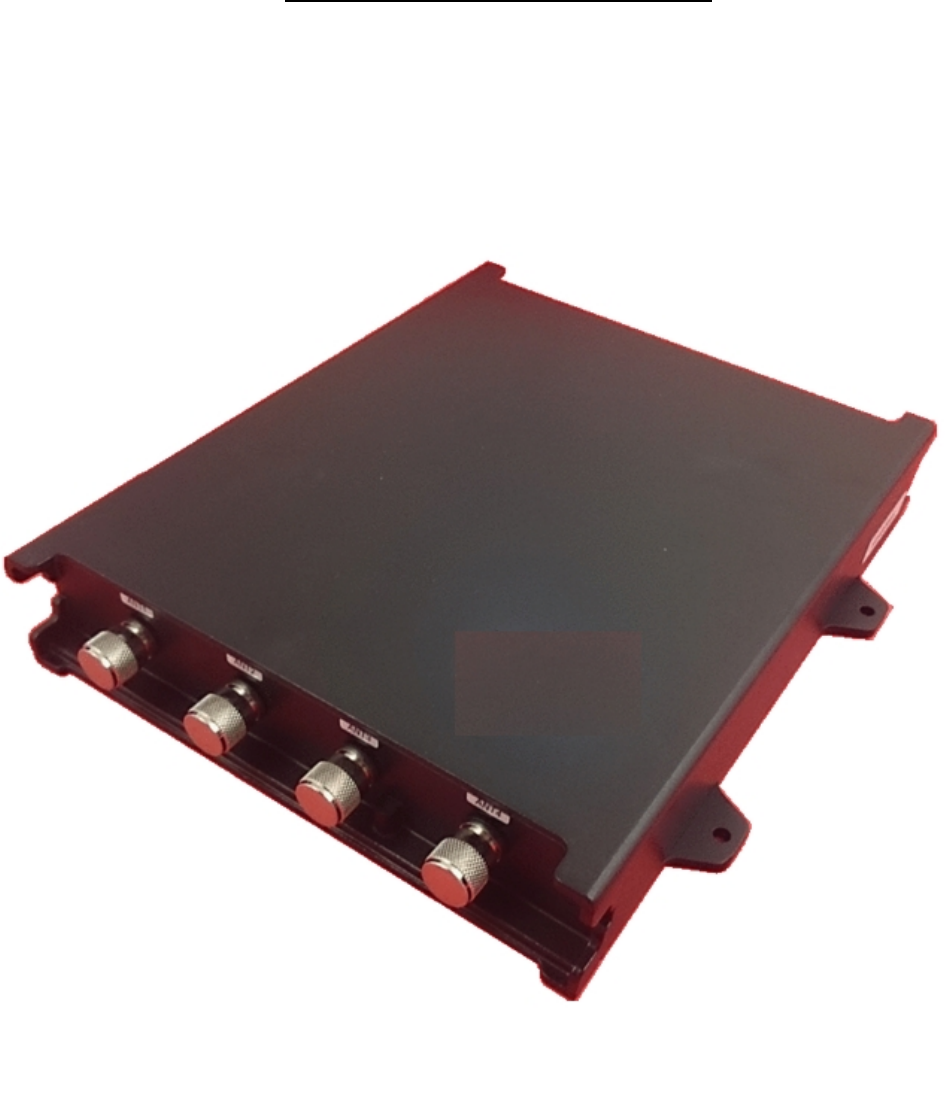
RDR-8018QN-NEO is a four-antenna, long-range (35' to 50') Radio Frequency
Identification (RFID) reader with TCP/IP interface and general purpose digital I/O (GP I/O
- four (4) input four (4) outputs) that works with most leading passive UHF passive tags.
This reader comes with a unique combination of long read range, ruggedized casing and
low power consumption. Its primary applications are asset management and tracking,
and fleet management applications.
In order to control the RDR-8018QN-NEO reader you will need the following:
Computer with Network connection
Host software (demo software or your own custom software).
RFID Tags (EPC Class 1 Gen 2, ISO Type B, etc)
1.1. SPECIAL FEATURES
Multi-Protocol: ISO-18000-6 Type B/C, EPC Class 1 Gen 2
Four (4) ports for wide range antennas allowing selection for different applications
Splash proof design for indoor or outdoor applications
Ruggedized housing
C
HAPT
ER 1

RDR-8018QN-NEO Page 5 3/1/2017
2. SPECIFICATIONS
Input voltage ........................................................... DC 12V
Input current ........................................................... 2.5A Max
Protocol language................................................... ISO 18000-6 Type B/C, EPC Class 1 Gen 2
Read range ............................................................ Depends on type & size of labels used
Output power .......................................................... Up to 3 Watts
Transmit frequency................................................. 902-928 MHz
Receiver frequency................................................. 902-928 MHz (Amplitude Modulated)
Operating temperature range ................................. -20C to +50C (-4F to 122F)
Color....................................................................... Black
Output data formats................................................ TCP/IP, Ethernet
GP I/O Input............................................................ 4-input, 4-output
GP I/O Connector ................................................... 10-pin MIL connector
Dimension............................................................... 7.6x8.5x1.6” (19.4x21.7x4cm)
Weight ....................................................................3.6lb (1.6kg)
Protection Class.......................................................IP 66
2.1. INPUT AND OUTPUT INTERFACES & CONNECTOR PIN ASSIGNMENT
(See Appendix section 6.1 for the interfaces)
2.1.1. Ethernet connector (RJ45)
Pin # Function description Pin # Function description
1 TX+
2 TX-
3 RX+
4 Spare+
5 Spare+
6 RX-
7 Spare-
8 Spare-
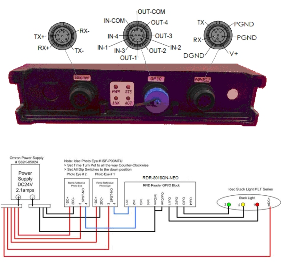
2.1.2. General Purpose Input/Output
Pin # Function description Pin # Function description
1 Input 1 6 Output Common
2 Input 2 7 Output 4
3 Input 3 8 Output 3
4 Input 4 9 Output 2
5 Input Common 10 Output 1
The four general-purpose inputs that use photo diodes are used to accept TTL input
commands. Each input requires 15 mA and 5V to activate. The four outputs are solid -
state relays, with 0.03 uA off-state leakage current and the ability to sink 120 mA at a
breakdown voltage of 400V DC. All outputs are protected with reverse clamping diodes,
and ready to drive inductive loads. The floating arrangement eliminates any ground loop
considerations.
RDR-8018QN-NEO Page 6 3/1/2017
See Appendix 6.2 for wiring diagram of a sample application.
2.2. MEASURING READ DISTANCE
Make sure you know the tag types. For instance, EPC tags must be pre -programmed to
be read. For certain readers and tags, user must also be mindful of the tag’s orientation
and the reader’s antenna orientation, what mounting surface the tags are designed for
and how the tags are supposed to be mounted. Any departure from its int ended purpose
will drastically affect the reader’s ability to energize the tag and its read range.
When measuring the reader’s read range, make sure that the tag is properly oriented to
the reader antenna, and for optimum performance, be sure the operator’s finger is not
within three (3) inches of the tag’s antenna surface.
RDR-8018QN-NEO Page 7 3/1/2017
3. INSTALLATION PROCEDURE
This section provides installation and operation information for RDR-8018QN-NEO readers.
3.1. PARTS LIST
Verify that all items listed below are present before the installation.
Part
QTY
1
RDR-8018QN-NEO reader
1
2
12 VDC wall plug power supply unit
1
3
RJ-45 Cable
1
4
Documentation and demo SW
1
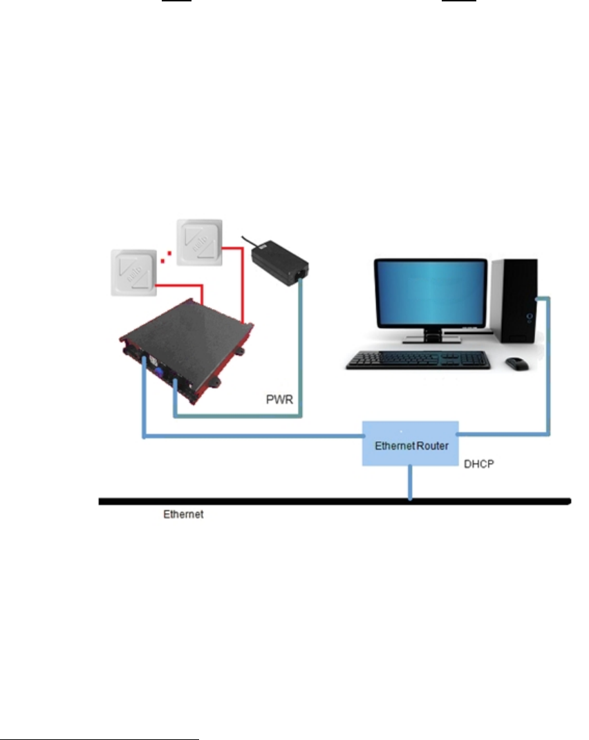
3.2. PREPARATION/SETUP
It is always a good idea to verify system operation before committing to a full -scale
installation. The following are the necessary steps to test reader’s operation in a static
environment
1
.
Figure 1 RDR-8018QN-NEO Setup in LAN
1
Warning: some fluorescent lighting may cause interference thereby degrading reader performance.
RDR-8018QN-NEO Page 8 3/1/2017
3.2.1. Installation Steps
oConnect reader to network with a RJ-45 cable at TCP/IP port
oPower up computer
oConnect the RJ-45 cable between the reader and connector labeled “Out” on the
12 V PS unit, connect from Ethernet Hub/Switch to where “In” is labeled. Plug in
power.
oCheck to ensure that all connections are secure. Make sure that all wires through
the cable clamps are anchored properly; avoid dangling wires that may become a
safety hazard.
oMount the Reader/Antenna using the screw posts to fasten to reader on the
desired mounting surface.
oLoad and launch the demo program on installation PC. Try Connect after filling in
the IP address of reader and then some commands once connected.
oPlace the RFID tags on the exact same locations as the final configuration
oMeasure tag’s read distance and confirm that read distance is correct.
RDR-8018QN-NEO Page 9 3/1/2017
4. Notes on Software Programming and System Operation
4.1. SET UP AND SYSTEM OPERATION
4.1.1. Setting Up RDR-8018QN-NEO
Power up with the 12-V power supply unit, connect to network through the Ethernet port
with RJ-45 cable.
4.1.2. Running a Custom Software Application or the Demo Program
If AWID Demo Program is not used, it is expected that user will launch a custom
software application to send commands defined in Neology MPR Communication
Protocol and/or the supporting SDK to the reader.
4.2. USERS NOTE
For System Integrators and/or Software Developers
System Integrators and/or Software developers should get familiar with the Neology MPR
Communication Protocol (Reference I) specifications and/or the supporting SDK for
developing applications that control MPR network readers.
For Custom System Users
For custom system user, please refer to your host software user guide for information
regarding system and software operations
For Demo Software Users
If you are using the AWID RFID demonstration software application which is .NET based
with easy-to-follow GUI operations, simply fill in the IP address of RDR-8018QN-NEO
installed then click “Connect” should get you started.
5. Reference
I. MPR Communication Protocol – Doc# 041487
RDR-8018QN-NEO Page 10 3/1/2017
6. Appendix
6.1. RDR-8018QN-NEO GPIO AND CONNECTOR ASSIGNMENT
6.2. SAMPLE WIRING DIAGRAM FOR GP I/O