Neoway Technology 1721 Wcdma Modem User Manual
Shenzhen Neoway Technology Co., Ltd Wcdma Modem
User manual

Neo_N703 WCDMA Module
User Guide
Version 1.0

Neo_N703 WCDMA ModuleDemo Board User Guide
Copyright © Neoway Technology Co., Ltd
i
Copyright © Neoway Technology Co., Ltd 2016. All rights reserved.
All Rights Reserved
No part of this document may be reproduced or transmitted in any form or by any means without prior
written consent of Shenzhen Neoway Technology Co., Ltd.
Trademarks and permissions
is the trademark of Neoway Technology Co., Ltd.
All other trademarks and trade names mentioned in this document are the property of their respective
holders.
Notice
This document is intended for system engineers (SEs), development engineers, and test engineers.
The information in this document is subject to change without notice due to product version update or
other reasons.
Every effort has been made in preparation of this document to ensure accuracy of the contents, but all
statements, information, and recommendations in this document do not constitute a warranty of any
kind, express or implied.
Neoway provides customers complete technical support. If you have any question, please contact
your account manager or email to the following email addresses:
Sales@neoway.com
Support@neoway.com
Website:
http://www.neoway.com

Neo_N703 WCDMA ModuleDemo Board User Guide
Copyright © Neoway Technology Co., Ltd
ii
Table of Contents
1 Getting to Know the N703---------------------------------------------------------------------------------------1
1.1 N703 Pin Description------------------------------------------------------------------------------------------------------2
1.2 N703 PCB Foot Print-------------------------------------------------------------------------------------------------------5
1.3 N703 Installation Guid----------------------------------------------------------------------------------------------------5
1.4 Requirements for the PC--------------------------------------------------------------------------------------------------7
2 Using N703 with Mini PCI Express Board on PC------------------------------------------------------------7
3 Using N703 with Embedded Main Board on PC------------------------------------------------------------8
3.1 N703 Embedded Main Board (Demo) description------------------------------------------------------------------8
3.2 Installing PL2303 Driver Guide on PC----------------------------------------------------------------------------------9
3.3 Installing Modulation Modem-----------------------------------------------------------------------------------------11
3.4 Setting Up a New Connection------------------------------------------------------------------------------------------16
4 Safety Information-----------------------------------------------------------------------------------------------19
4.1 Interference----------------------------------------------------------------------------------------------------------------19
4.2 Medical Device------------------------------------------------------------------------------------------------------------19
4.3 Area with Inflammables and Explosives----------------------------------------------------------------------------19
Neo_N703 WCDMA ModuleDemo Board User Guide
Copyright © Neoway Technology Co., Ltd
1
Thank you for purchasing Neoway N703 WCDMA Module
Note:
This manual briefly describes the preparation, the process for installing and safety precautions for using
Neoway N703 WCDMA Module.
You are recommended to read the manual before using the N703.
The signal strength and the transmission rate are affected by the actual environment.
1 Getting to Know the N703
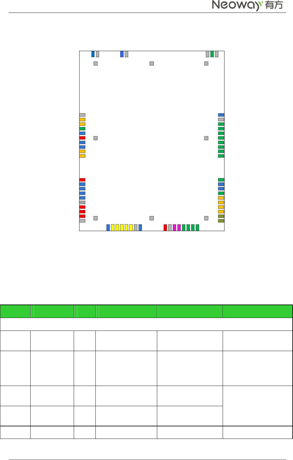
The follow figure shows the appearance of the N703.The actual produce may differ.
They are used to connect antennas.N703 has an external antenna.
The max gain which is allowed of external antenna is:
900M: <2.1dBi
1800M: <2.6dBi
2100M: <4.3dBi
850M: <0dBi
1900M: <2.6dBi
Neo_N703 WCDMA ModuleDemo Board User Guide
Copyright © Neoway Technology Co., Ltd
2
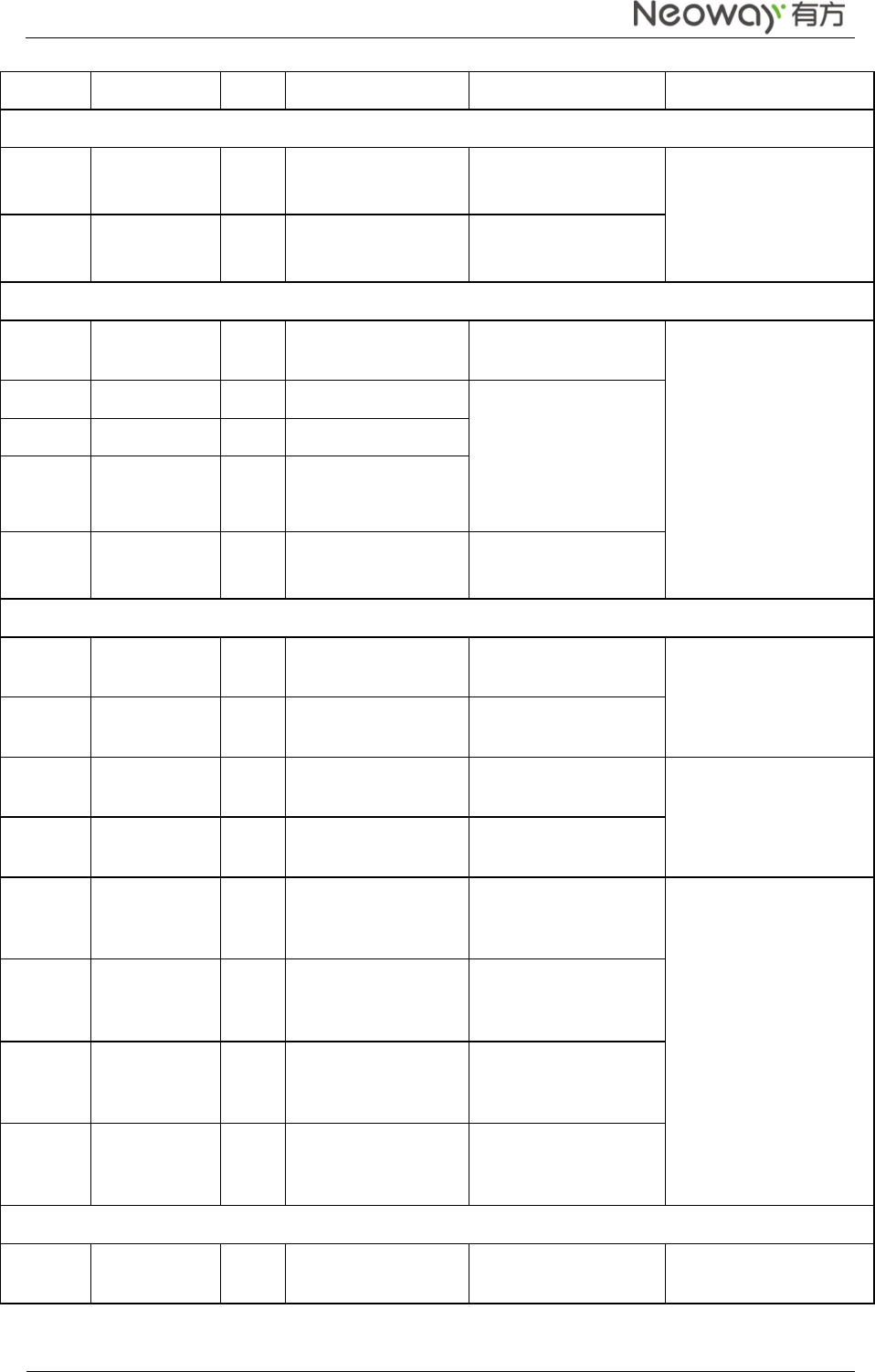
Top view of N703
1
3
2
4
5
6
7
8
9
10
11
13
14
15
16
17
18
19
20
2 1
2 2
2 3
2 4
2 5
2 6
2 7
2 8
2 9
3 0
3 1
3 2
3 3
3 4
3 5
3 6
37
38
39
40
41
42
43
44
45
46
47
48
49
50
51
52
53
54
55
56
5 7
5 8
5 9
6 0
6 1
6 2
6 3
GND
GND
GND GND GND
GND
GNDGND
GND
GND
GND
MIC1_P
G N D
G N D
G N D
G N D
I2C_SCL
I2C_SDA
NET_LIGHT
NC
VDD_EXT_1V8
NC
NC
UART_RXD
UART_TXD
VDD_EXT_2V6
NC
NC
NC
NC
VBAT
VBAT
VBAT
N C
N C
A N T
NC
VUIM
UIM_RES ET
UIM_DATA
UIM_DETEC T
UIM _CLK
NC
GND
ADC0
UBS_DM
USB_DP
VBUS
RESET
PWRKEY
SPI_CLK
SPI_MOSI
SPI_MISO
SPI_CS
RING
NC
NC
DTR
NC
GND
MIC1_N
MIC2_P
MIC2_N
SPK_OUT_N
SPK_OUT_P
REC_P
REC_N
N703
TOP VIEW
12
VDD_EXT_2V6
GND
GND
ADC1
1.1 N703 Pin Description
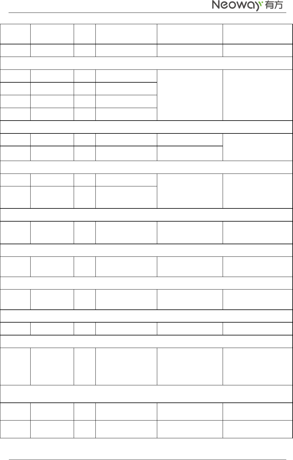
N703 pin description
Pin Name I/O Function Level Feature (V) Remarks
Power Supply and Switch Interfaces
17/18/19
VABT P Main power supply
input 3.5 V to 4.3 V (3.9 V is
recommended)
1/16/20/
27/30/33
/55/57/5
9/60/62
GND P GND
6 VDD_EXT_1
V8 P 1.8 V power supply
output Supply power for IO
level shifting circuit.
Load capability: <20
mA
11/29 VDD_EXT_2
V6 P 2.6 V power supply
output
37 RESET DI Reset input -0.3V<VIL<0.6 Low level
Neo_N703 WCDMA ModuleDemo Board User Guide
Copyright © Neoway Technology Co., Ltd
3
38 PWRKEY DI ON/OFF control
1.2V
<V
IH
<
2.1V
Low level
UART Interface
9 UART_RXD DI UART data receive -0.3V<VIL<0.6
1.2V<VIH<2.1V
Data communication
10 UART_TXD DO UART data transmit 1.35V<VOL<1.8V
0<VOH<0.45V
UIMInterfaces
22 VUIM P UIM power supply
output
Compatible with
1.8/2.85 V UIM card
23 UIM_RESET
DO UIMreset -0.3V<VIL<0.35*VUIM
0.65*VUIM<VIH<VUIM
+0.3V
VUIM
-0.45<VOH<VUIM
0<VOL<0.45V
24 UIM_DATA DI/O
UIMdata I/O
25 UIM_CLK DO UIMclock output
26 UIM_DETECT DI UIM detect -0.3V<VIL<0.6
1.2V<VIH<2.1V
Audio Interfaces
47 REC_N AO Negative electrode of
receiver output
Class AB differential
receiver amplifier
48 REC_P AO Positive electrode of
receiver output
49 SPK_OUT_P
AO Positive electrode of
speakeroutput
Class Ddifferential
speaker amplifier
50 SPK_OUT_N
AO Negative electrode of
speakeroutput
51 MIC2_N AI
Negative electrode of
differential MIC
input
MIC bias embedded
52 MIC2_P AI
Positive electrode of
differential MIC
input
53 MIC1_N AI
Negative electrode of
differential MIC
input
54 MIC1_P AI
Positive electrode of
differential MIC
input
USB Interfaces
34 USB_DM DI/O
USB data negative
signal USB2.0, used for
firmware download and
Neo_N703 WCDMA ModuleDemo Board User Guide
Copyright © Neoway Technology Co., Ltd
4
35 USB_DP DI/O
USB data positive
signal
data transmission
36 VBUS P USB voltage test 4.2V~5.5V, typically 5V
SPI Interfaces
39 SPI_CLK DO SPIclock output
-0.3V<VIL<0.6,
1.2V<VIH<2.1V,0<VO
L<0.45V
1.35V<VOH<1.8V
Used in host mode
40 SPI_MOSI DI/O
SPIdata input
41 SPI_MISO DI/O
SPI data output
42 SPI_CS DO SPI enabling
ADC
31 ADC0 AI ADC0input 12 bit, detectable
voltage range: 0 V to 2.1
V
32 ADC1 AI ADC1input
I2C Interfaces
2 I2C_SCL DO I2C clock output -0.3V<VIL<0.6,
1.2V<VIH<2.1V,
1.35V<VOH<1.8V
0<VOH<0.45V
Connected to I2C
components
3 I2C_SDA DI/O
I2C data cable
Network LED Indicator
4 NET_LIGHT
DO Indicate network
status
-0.3V<VOL<0.91V
2.15V<VOH<2.6V
Sleep Mode Controlling
46 DTR DI Sleep mode control -0.3V<VIL<0.6,
1.2V<VIH<2.1V
SMS and Incoming Call Ring
43 RING DO SMS and incoming
call ring
0<VOL<0.45V,
1.35V<VOH<1.8V
Antenna Interfaces
58 ANT AI/O
2G/3G antenna 50 Ω impedance
NC Interfaces
5/7/8/21/
28/44/45
/56 NC Reserved pins
Leave them not
connected.
Do not pull up or down.
Reserved RF Interfaces
61 NC
63 NC
Neo_N703 WCDMA ModuleDemo Board User Guide
Copyright © Neoway Technology Co., Ltd
5
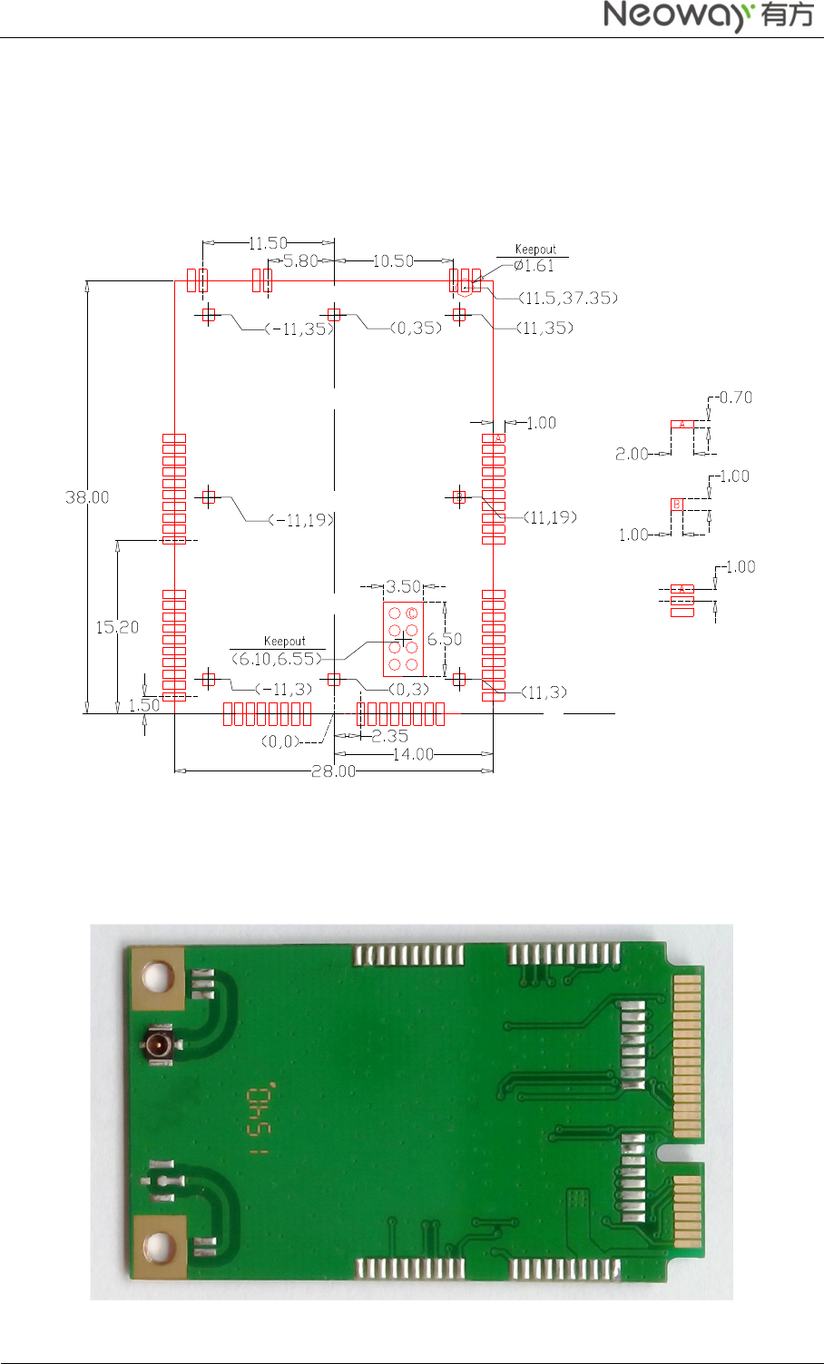
1.2 N703 PCB Foot Print
LCC packaging is adopted to package the pins of the N703 module. 0 shows the recommended PCB
footprint. (Unit: mm)
PCB foot print recommended for N703
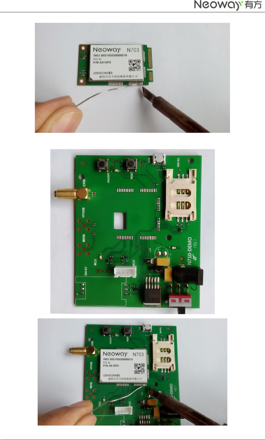
1.3 N703 Installation Guid
Welding the N703 onto the Main Board of PC 、Mini PCI Board or other Embedded Main Board.
For Example, Welding the N703 onto Mini PCI Board.
Neo_N703 WCDMA ModuleDemo Board User Guide
Copyright © Neoway Technology Co., Ltd
6
For Example, Welding the N703 onto Embedded Main Board.
Neo_N703 WCDMA ModuleDemo Board User Guide
Copyright © Neoway Technology Co., Ltd
7
1.4 Requirements for the PC
To use the N703, the PC must meet the following requirements:
Windows 2000 SP4, Windows Xp SP2, Windows Vista, Windows 7-10 and Linux 2.6.18 or above.
The hardware of your PC must meet or exceed the recommended system requirements for the
installed version of OS.
Display resolution:800*600 or above.
At lest one WWAN Mini PCI Express interface or one USB interface .
To use the N703, the MCU must meet the following requirements:
At lest one USB interface or one Uart interface.
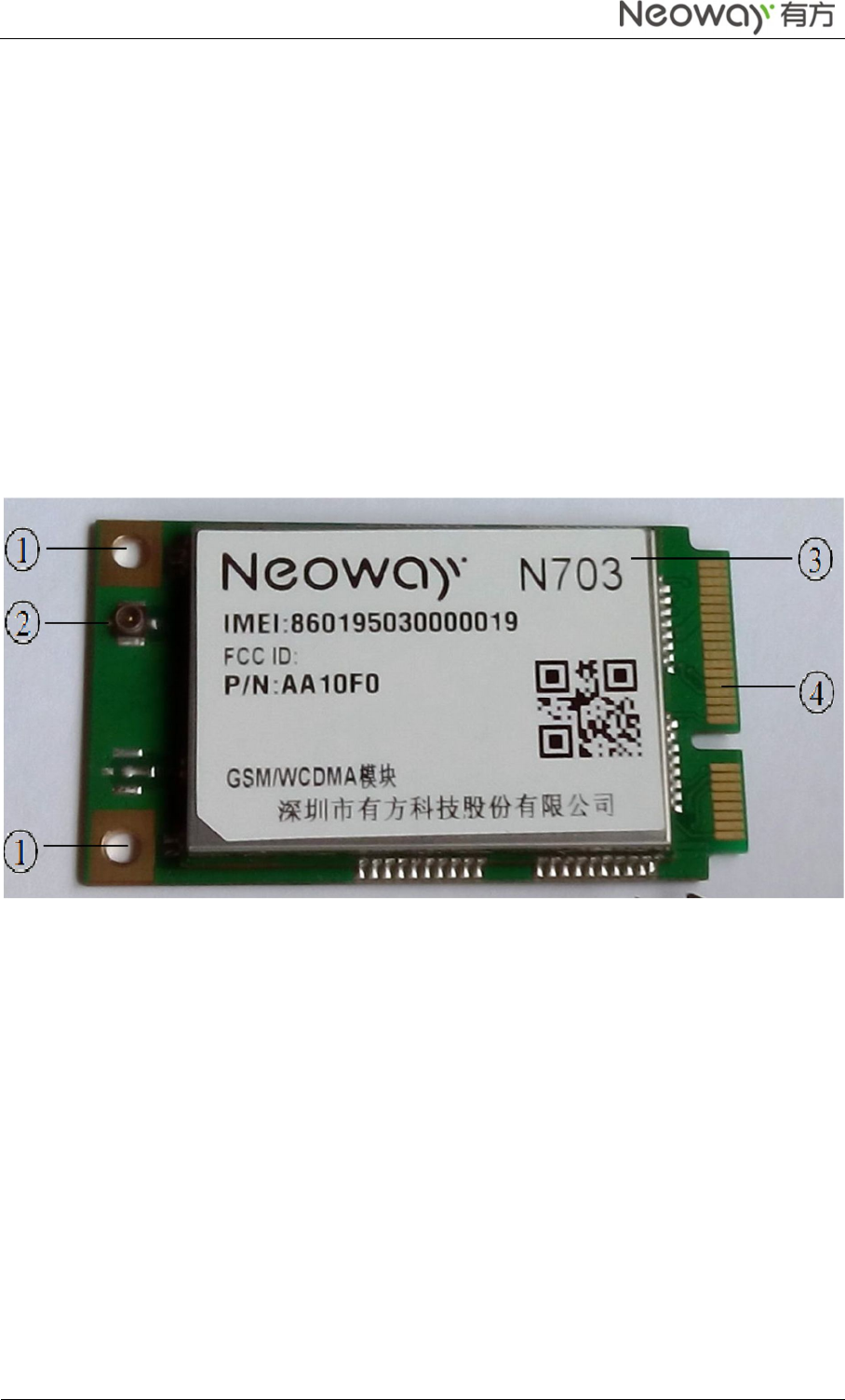
2 Using N703 with Mini PCI Express Board on PC
○
1 Screw holes
○
2 Main antenna
○
3 N703 Module
○
4 Mini PCI Express connector
Installing the N703 Mini PCI Express Board on the Main Board of the PC
Step 1 Insert the mini PCI Express connector of the N703 into the WWAN Mini PCI Express
interface on the main board of the PC.
Step 2 Press downward to fic the N703 in the module slot.
Step 3 Use a screwdriver to fix the N703 onto the main board of the PC with two screws provided in
the packing box
Step 4 Insert the connector of the main antenna into the Main antenna interface of the N703 Mini
PCI Board.
Neo_N703 WCDMA ModuleDemo Board User Guide
Copyright © Neoway Technology Co., Ltd
8
3 Using N703 with Embedded Main Board on PC
You can also use N703 Module with your computer to connect to the internet, One N703 Module and a
Embedded Main Board (Demo) is needed.
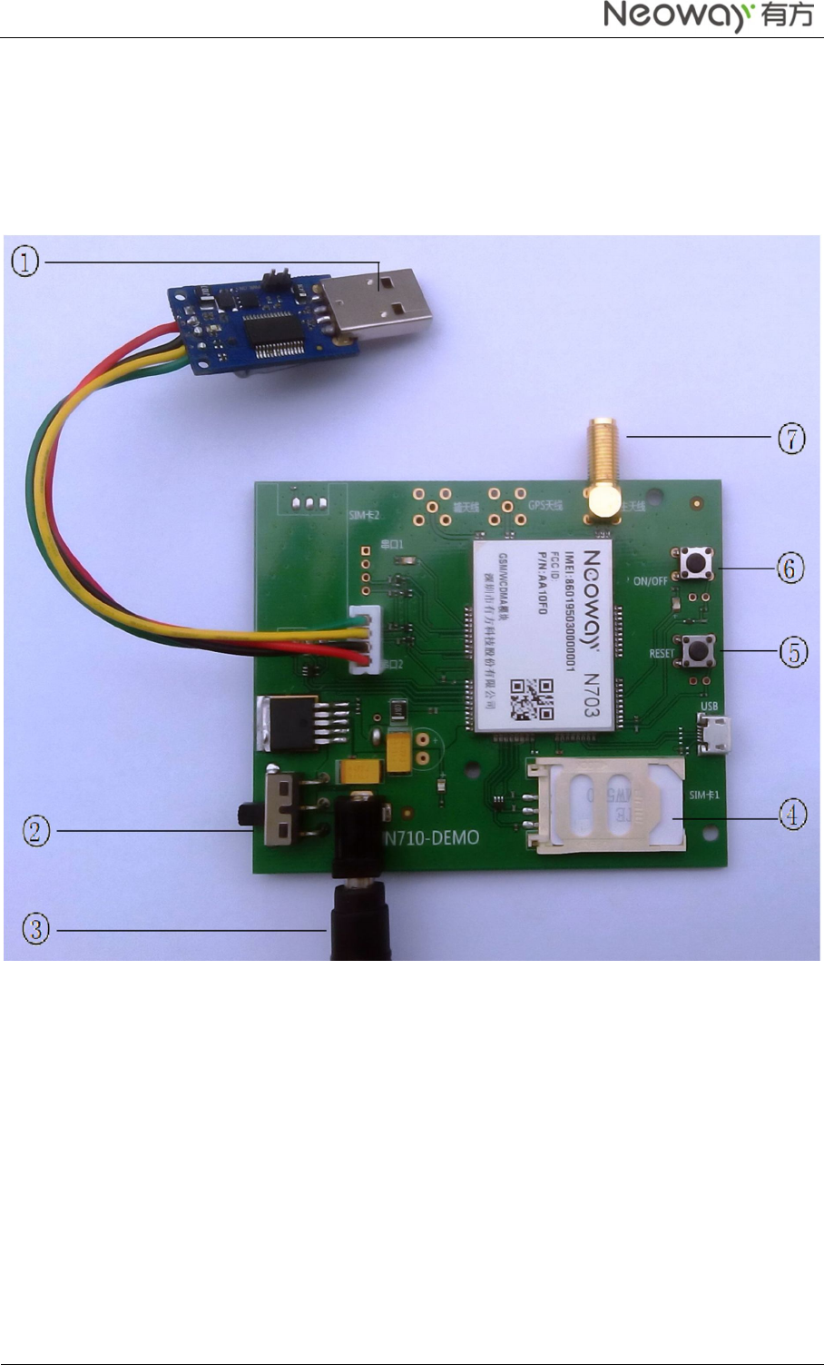
3.1 N703 Embedded Main Board (Demo) description
○
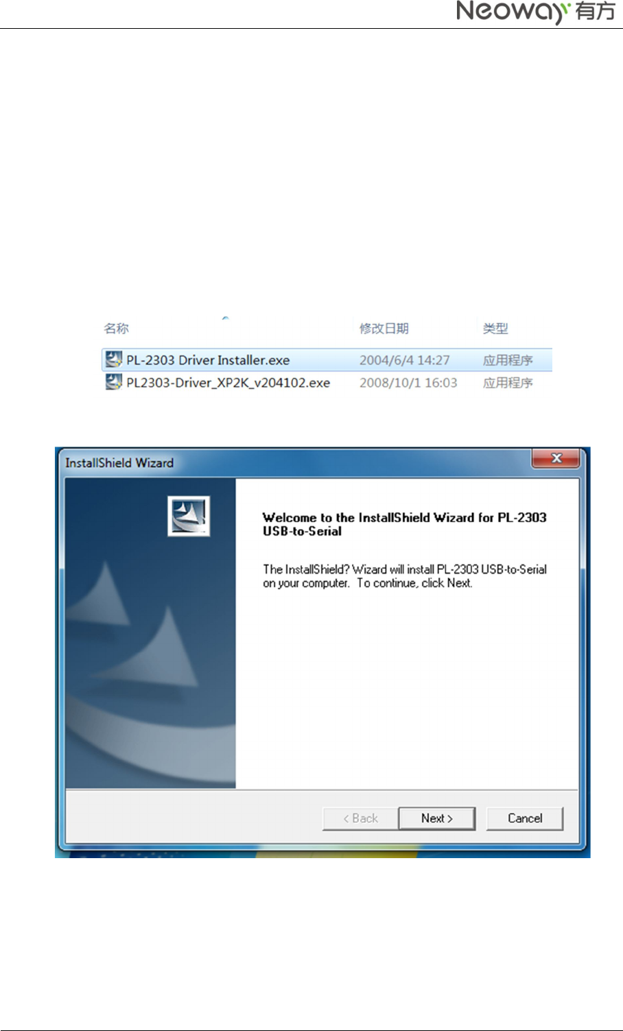
1 Connect USB-to-Serial (PL2303) to a computer.
○
3 Connect to a DC 5V power supply.
○
2 DC 5V power supply switch.
○
4 Insert a GSM or WCDMA SIMcard for Using.
○
5 N703 Module RESET Key.
○
6 N703 Module ON/OFF Key.
○
7 N703 Module antenna interfaces
Neo_N703 WCDMA ModuleDemo Board User Guide
Copyright © Neoway Technology Co., Ltd
9
Then you can Starting the N703 Demo Board with next 4 Step on your computer:
Step 1 T urn on the DC 5V power supply switch. The LED indicator of the N703 Demo board is on.
Step 2 Short press on the On/Off button. The N703 demo board is started.
Step 3 Installing PL2303 Driver Guide on PC
Step 4 Installing Modulation Modem
3.2 Installing PL2303 Driver Guide on PC
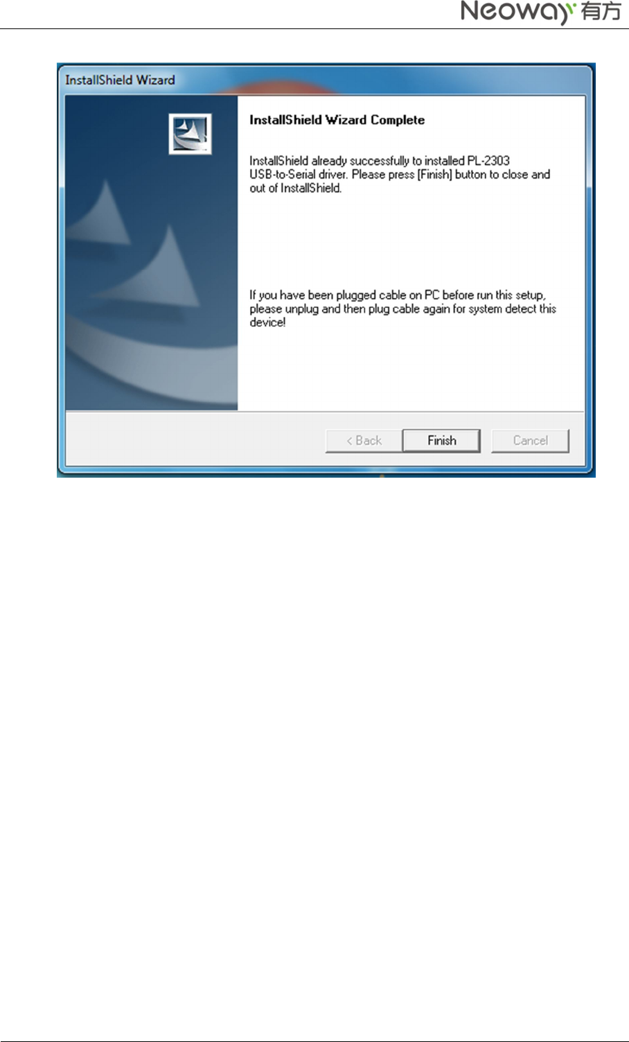
Install the PL2303 driver on the computer.
Step 1 Selectthe correct version of the driver based on your operating system.
Step 2 Double-click the installer.
Step 3 ClickNext and then Finish.
The driver is installed successfully.
Neo_N703 WCDMA ModuleDemo Board User Guide
Copyright © Neoway Technology Co., Ltd
10
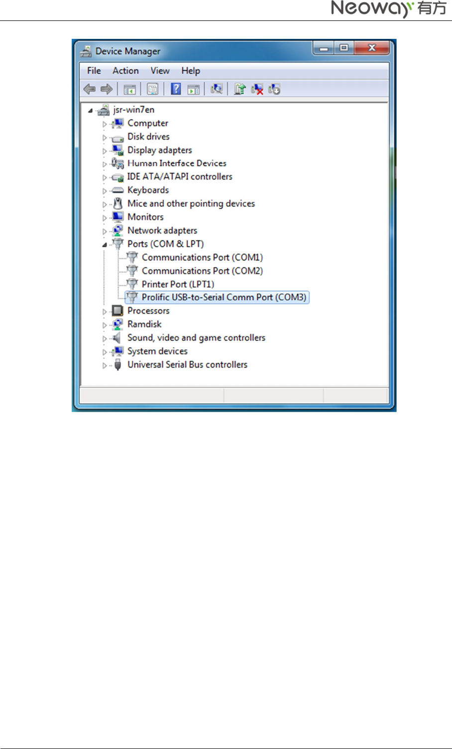
Step 4 In Device Manager, check the ports. You can see the USB-to-Serial in the list.
Neo_N703 WCDMA ModuleDemo Board User Guide
Copyright © Neoway Technology Co., Ltd
11
3.3 Installing Modulation Modem
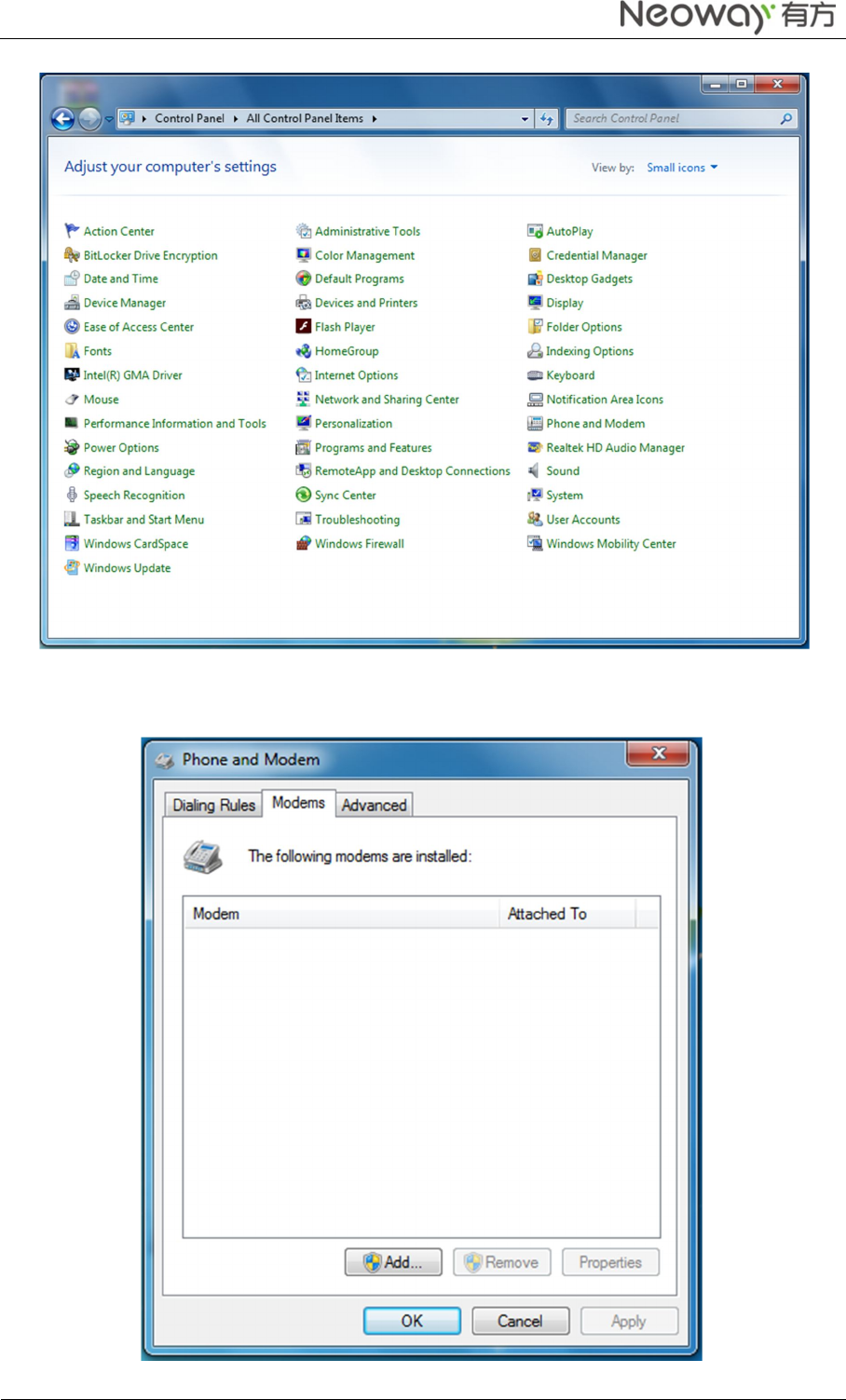
Step 1 Click Start > Control Panel.
Step 2 In Control Panel, click Phone and Modem.
The Phone and Modem dialog box is displayed.
Neo_N703 WCDMA ModuleDemo Board User Guide
Copyright © Neoway Technology Co., Ltd
12
Step 3 On the Modems tab of Phone and Modem, click Add.
Neo_N703 WCDMA ModuleDemo Board User Guide
Copyright © Neoway Technology Co., Ltd
13
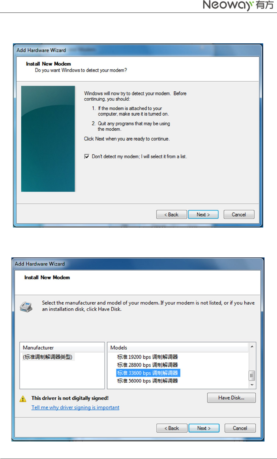
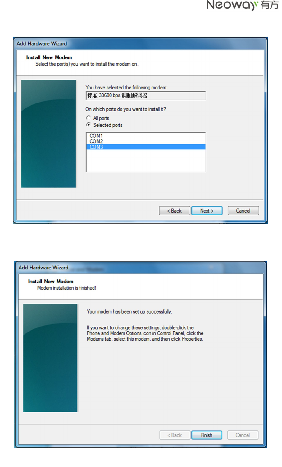
Step 4 In the Add Hardware Wizard, select Don’t detect my modem; I will select it from a list and
click Next.
Step 5 Select the Standard 33600bps Modem and click Next.
Neo_N703 WCDMA ModuleDemo Board User Guide
Copyright © Neoway Technology Co., Ltd
14
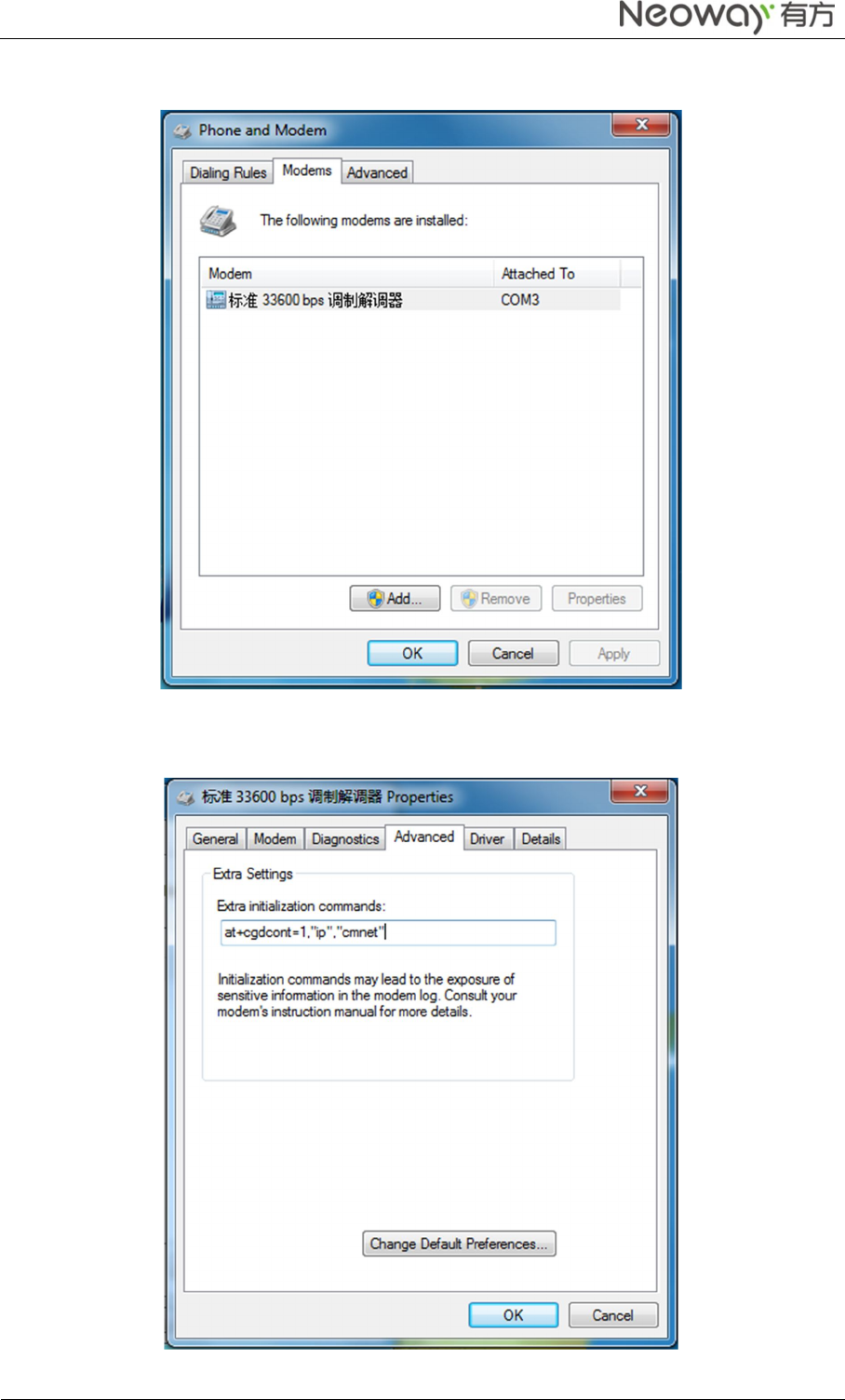
Step 6 ClickSelected ports, select the correct port, and click Next.
Step 7 Click Finish.
The modem is installed successfully.
Neo_N703 WCDMA ModuleDemo Board User Guide
Copyright © Neoway Technology Co., Ltd
15
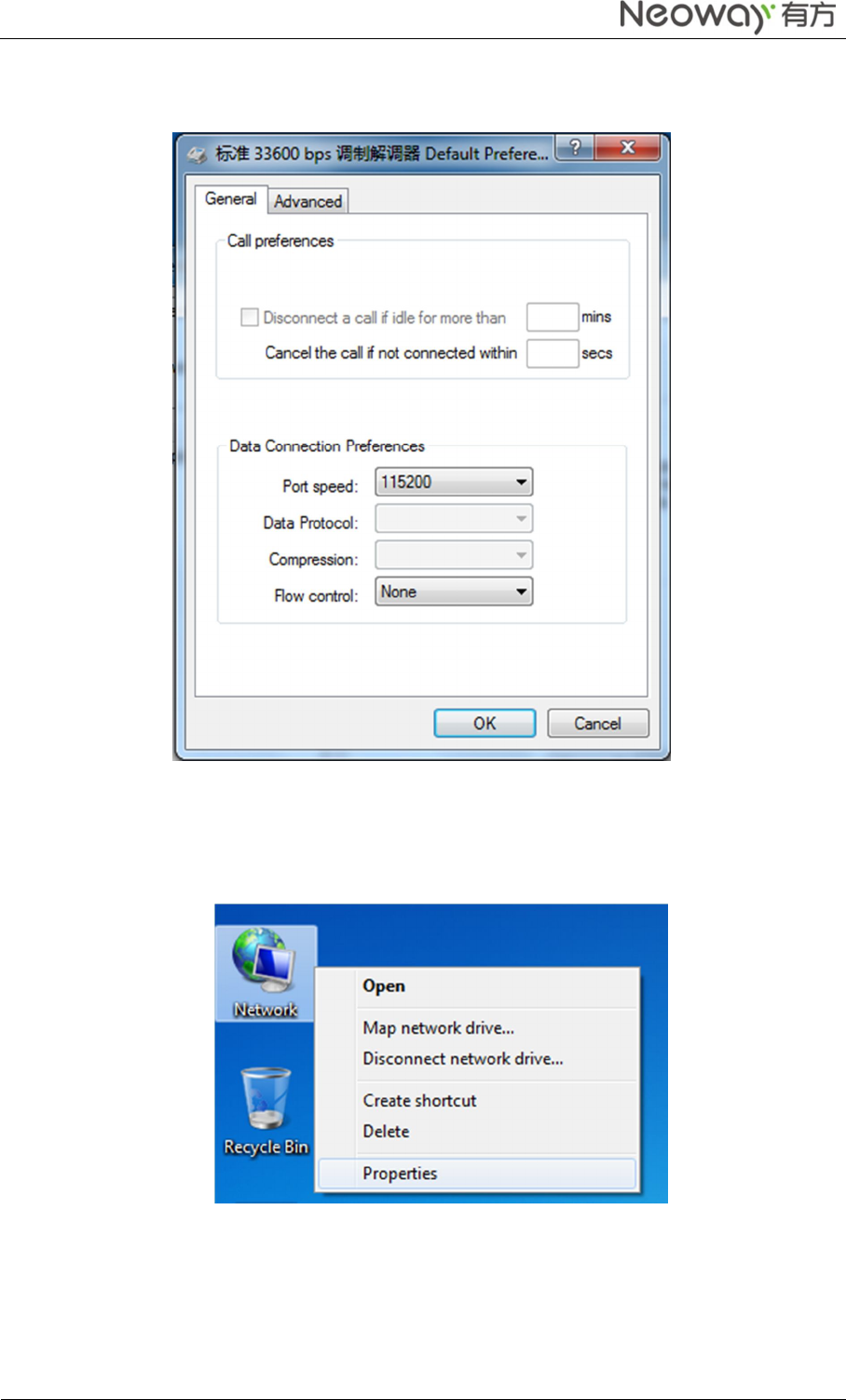
Step 8 In the following dialog box, select current port and click Properties.
Step 9 On the Advanced tab, add at+cgdcont=1,"ip","cmnet" to Extra initialization commands:.
Neo_N703 WCDMA ModuleDemo Board User Guide
Copyright © Neoway Technology Co., Ltd
16
Step 10 Click Change Default Preferences and set the Flow control to None. Click OK.
The modem setting is completed.
3.4 Setting Up a New Connection
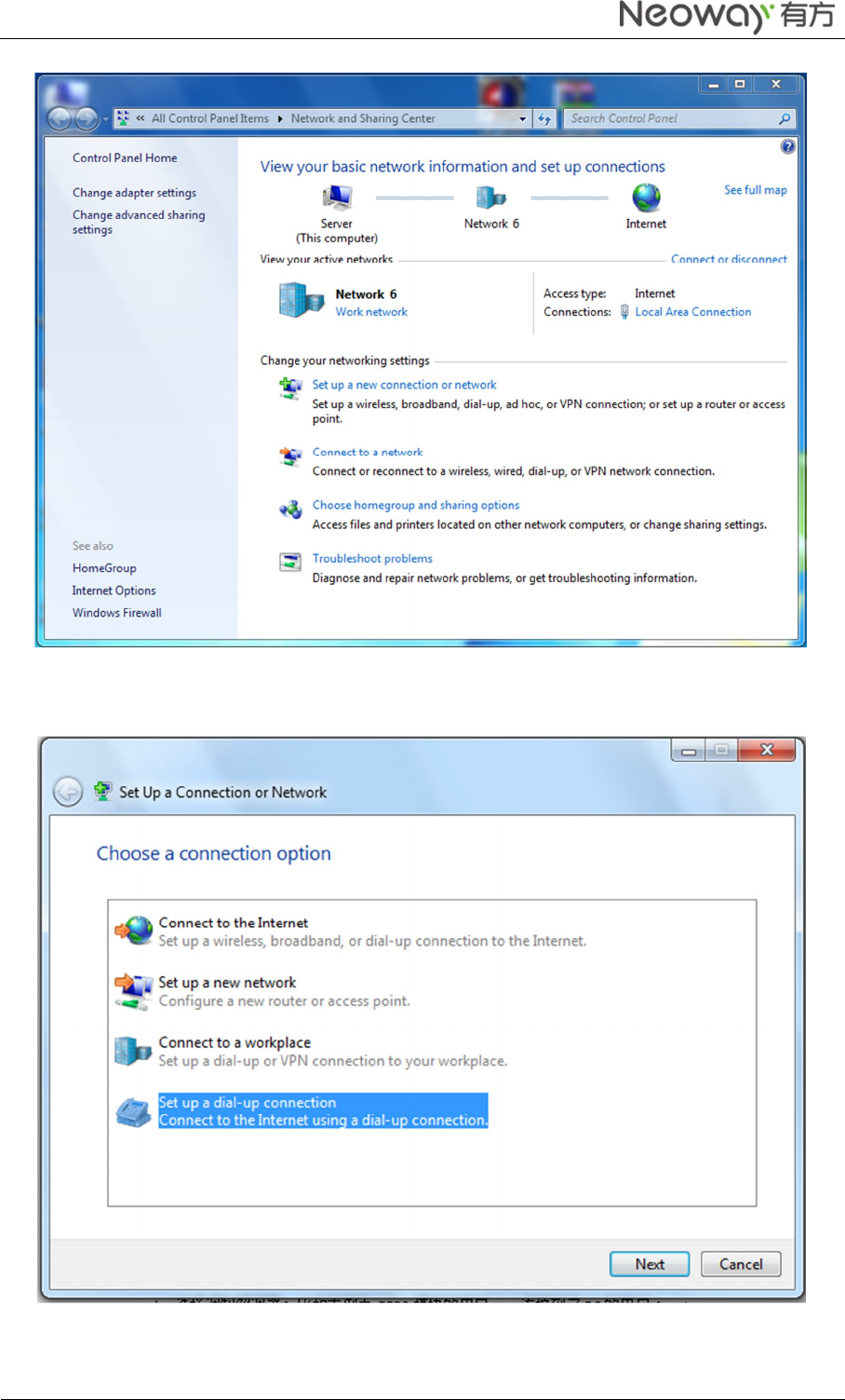
Step 1 Right-clickNetwork and choose Properties from the pop-up menu.
Step 2 In the Network and Sharing Center, click Set up a new connection or network.
Neo_N703 WCDMA ModuleDemo Board User Guide
Copyright © Neoway Technology Co., Ltd
17
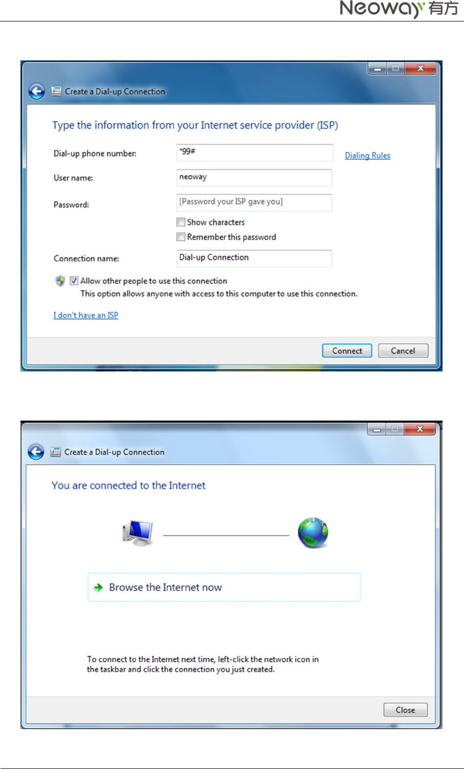
Step 3 On the Choose a connection optionpage, select Set up a dial-up connectionand click Next.
Neo_N703 WCDMA ModuleDemo Board User Guide
Copyright © Neoway Technology Co., Ltd
18
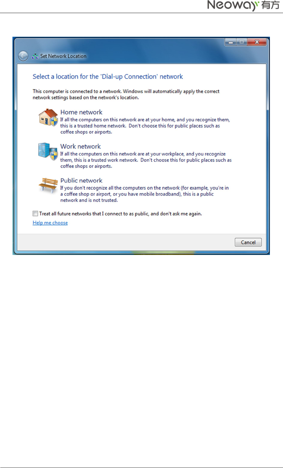
Step 4 In the following dialog box, fill information as shown and click Connect.
If the following page is displayed after you click Connect, dial-up connection is set up successfully.
Neo_N703 WCDMA ModuleDemo Board User Guide
Copyright © Neoway Technology Co., Ltd
19
Step 5 On the Set Network Location page, select your location. You can browse the internet now.
4 Safety Information
Read the safety information carefully to ensure the correct and safe use of your wireless device.
4.1 Interference
Do not use your wireless device if using the device is prohibited or when it causes danger or interference
with electric devices.
4.2 Medical Device
Do not use your wireless device and follow the rules and regulations set forth by the hospitals and
health car facilities.
Some wireless devices may affect the performance of the hearing aids.For any such problems,consult
your service provider.
If you are using an electronic medical device, consult the doctor or device manufacturer to confirm
whether the radio wave affects the operation of this device.
4.3 Area with Inflammables and Explosives
To prevent explosions and fires and fires in areas that are stored with inflammable and explosive devices,
do not use your wireless device and observe the veles.Areas stored with inflammables and explosives
include but are not limited to the following

Neo_N703 WCDMA ModuleDemo Board User Guide
Copyright © Neoway Technology Co., Ltd
20
Gas station.
Fuel depot (such as the bunk belw the deck of a ship).
Container/Vehicle for storing or transporting fuels or chemical products.
Ares where air contains chemical substances and particles (such as granule,dust,or metal powder).
Area indicated with the “Explosives” sign.
Area indicated with the “Power off bi-direction wireless equipment” sign.
Area where you are generally suggested to stop the engine of a vehicle.
Federal Communications Commission Notice (United States): Before a wireless device model is available
for sale to the public, it must be tested and certified to the FCC that it does not exceed the limit established by
the government-adopted requirement for safe exposure.
FCC Statement
This device complies with part 15 of the FCC Rules. Operation is subject to the condition that this device
does not cause harmful interference.
Warning: Changes or modifications not expressly approved by the party responsible for compliance could
void the user's authority to operate the equipment.
The antenna(s) used for this transmitter must be installed to provide a separation distance of at least 20cm
from all persons and must not be co-located or operate in conjunction with any other antenna or transmitter.
NOTE: This equipment has been tested and found to comply with the limits for a Class B digital device,
pursuant to Part 15 of the FCC Rules. These limits are designed to provide reasonable protection against
harmful interference in a residential installation. This equipment generates, uses and can radiate radio
frequency energy and, if not installed and used in accordance with the instructions, may cause harmful
interference to radio communications. However, there is no guarantee that interference will not occur in a
particular installation. If this equipment does cause harmful interference to radio or television reception,
which can be determined by turning the equipment off and on, the user is encouraged to try to correct the
interference by one or more of the following measures:
-- Reorient or relocate the receiving antenna.
-- Increase the separation between the equipment and receiver.
-- Connect the equipment into an outlet on a circuit different from that to which the receiver is connected.
-- Consult the dealer or an experienced radio/TV technician for help.
If the FCC identification number is not visible when the module is installed inside another device,
then the outside of the device into which the module is installed must also display a label
referring to the enclosed module. This exterior label can use wording such as the following:
“Contains Transmitter Module FCC ID: PJ7-1721” or “Contains FCC ID: PJ7-1721”
For PCB Antenna Module: