Neptune Technology Group L900M L900M User Manual Manual
Neptune Technology Group Inc. L900M Manual
Manual

5015 B.U. Bowman Drive Buford, GA 30518 USA
Certification Exhibit
FCC ID: P2SL900M
IC: 4171B-L900M
FCC Rule Part: 15.247
ISED Canada Radio Standards Specification: RSS-247
Project Number: 72126503
Manufacturer: Neptune Technology Group Inc.
Model: L900M
Manual
L900™ MIU Pit Installation and Maintenance Guide
L900™ MIU Pit Installation and Maintenance Guide

L900™ MIU Pit Installation and Maintenance Guide
Copyright
This manual is an unpublished work and contains the trade secrets and
confidential information of Neptune Technology Group Inc., which are not to be
divulged to third parties and may not be reproduced or transmitted in whole or
part, in any form or by any means, electronic or mechanical for any purpose,
without the express written permission of Neptune Technology Group Inc. All
rights to design or inventions disclosed herein, including the right to manufacture,
are reserved to Neptune Technology Group Inc.
The information contained in this document is subject to change without notice.
Neptune reserves the right to change the product specifications at any time
without incurring any obligations.
Trademarks used in this manual
L900 and ProRead are trademarks of Neptune Technology Group Inc.
ARB, E-CODER, MACH 10, and R900 are registered trademarks of
Neptune Technology Group Inc. Other brands or product names are
trademarks or registered trademarks of their respective holders.
FCCNotice
This device complies with Part 15 of the FCC Rules. Operation is subject to the
following two conditions: (1) this device may not cause harmful interference, and
(2) this device must accept any interference received, including interference that
may cause undesired operation.
Note: This equipment has been tested and found to comply with the limits for a
Class B digital device, pursuant to Part 15 of the FCCRules. These limits are
designed to provide reasonable protection against harmful interference in a
residential installation. This equipment generates, uses, and can radiate radio
frequency energy and if not installed and used in accordance with the instruction,
may cause harmful interference to radio communications. However, there is no
guarantee that interference will not occur in a particular installation. If this
equipment does not cause harmful interference to radio or television reception,
which can be determined by turning the equipment off and on, the user is
encouraged to try to correct the interference by one or more of the following
measures.
lReorient or relocate the receiving antenna.
lIncrease the separation between the equipment and receiver.
lConnect the equipment into an outlet on a circuit different from that to which
the receiver is connected.
lConsult the dealer or an experienced radio/TV technician for help.
RF Exposure Information
This equipment complies with the FCC RF radiation requirements for
uncontrolled environments. To maintain compliance with these requirements, the
antenna and any radiating elements should be installed to ensure that a
minimum separation distance of 20cm is maintained from the general population.

Changes or modifications not expressly approved by the party
responsible for compliance could void the user's authority to
operate the equipment.
Professional Installation
In accordance with section 15.203 of the FCC rules and regulations, the L900
MIU must be professionally installed by trained utility meter installers.
Industry Canada (IC) Statements:
Section 8.4 of RSS-GEN
This Device complies with Industry Canada License-exempt RSS standard(s).
Operation is subject to the fol¬lowing two conditions: 1) this device may not
cause interference, and 2) this device must accept any interfer¬ence, including
interference that may cause undesired operation of the device.
Cet appareil est conforme aux normes RSS exonérées de licence d'Industrie
Canada. L'opération est soumise aux deux conditions suivantes: 1) cet appareil
ne doit pas provoquer d'interférence, et 2) cet appareil doit accepter toute
interférence, y compris les interférences pouvant entraîner un fonctionnement
indésirable de l'appareil.
Section 8.3 of RSS-GEN
Under Industry Canada regulations, this radio transmitter may only operate using
an antenna of a type and max¬imum (or lesser) gain approved for the transmitter
by Industry Canada. To reduce potential radio interference to other users, the
antenna type and its gain should be so chosen that the equivalent isotropically
radiated power (e.i.r.p.) is not more than that necessary for successful
communication.
This radio transmitter IC: 4171B-L900M has been approved by Industry Canada to
operate with the antenna types listed below with the maximum permissible gain
and required antenna impedance for each antenna type indicated. Antenna types
not included in this list, having a gain greater than the maximum gain indicated for
that type, are strictly prohibited for use with this device.
lMaximum permissible gain of +1 dBi and required impedance of 75 ohm.
lApproved Antenna type(s)
oR900 Pit Antenna, part number 12527-XXX
En vertu de la réglementation d'Industrie Canada, cet émetteur radio ne peut
fonctionner qu'avec une antenne d'un type et un gain maximal (ou inférieur)
approuvé pour l'émetteur par Industrie Canada. Pour réduire les interférences
radio potentielles avec d'autres utilisateurs, le type d'antenne et son gain
devraient être choisis de manière à ce que la puissance rayonnée
isotropiquement équivalente (e.i.r.p.) ne soit pas supérieure à celle nécessaire à
une communication.
Cet émetteur radio IC: 4171B-L900M a été approuvé par Industrie Canada pour
fonctionner avec les types d'antennes énumérés ci-dessous avec le gain
maximal admissible et l'impédance d'antenne requise pour chaque type
d'antenne indiqué. Les types d'antenne non inclus dans cette liste, ayant un gain
supérieur au gain maximal indiqué pour ce type, sont strictement interdits pour
être utilisés avec ce périphérique.
lGain maximal admissible de +1 dBi et impédance requise de 75 ohms.
lType (s) d'antenne approuvé
oR900 Pit antennaaximum
L900™ MIU Pit Installation
andMaintenance Guide
Literature No. IM L900 Pit MIU 09.17
Part No. 13381-001
Neptune Technology Group Inc.
1600 Alabama Highway 229
Tallassee, AL 36078
Tel: (800) 633-8754
Fax: (334) 283-7293
Copyright © 2017
Neptune Technology Group Inc.
All Rights Reserved

Contents
Chapter 1: Product Description 1
Product Description 2
L900 MIU Programming 2
RF Protocol Error Detection 2
RF Frequency Control Algorithm 2
RF Transmission Period and Randomness 2
Low Battery RF Emissions 2
Chapter 2: L900 Specifications 3
Electrical Specifications 3
Transmitter Specifications 3
Encoder Register Interface 3
Specifications - L900 MIU Pit 4
Environmental Conditions 4
Functional Conditions 4
Dimensions and Weight 4
Chapter 3: General Installation Guidelines 7
Tools and Materials 7
Safety and Preliminary Checks 8
Verifying/Preparing the Encoder Register 8
Installation of a Register (Non Pre-Wired or Potted Only) 9
Chapter 4: Pit Installation 13
Prior to Installation 13
Storage 13
Unpacking 13
Tools and Materials 14
Site Selection 14
L900 MIU Pit Installation 15
Installing the Antenna 16
L900 MIU Pit Installation and Maintenance Guide v

Begin the Installation 17
Threading the F-Connector 18
Installing the Scotchloks 19
Connecting the Splice Tube 21
Tying the Cable and Magnet Swiping the L900 MIU 22
Testing the Installation 23
Chapter 5: Data Logging Extraction 25
About Data Logging 25
Accessing Data Logging 25
Initializing the Data Logger 27
Initiating RF-Activated Data Logging 30
Sample Data Logging Graphs 31
Off-Cycle Data Extraction 33
R900 Belt Clip Transceiver 34
Chapter 6: Maintenance and Troubleshooting 35
Six- and Four-Wheel Encoders 35
Six-Wheel Encoders Normal Operation 35
Four-Wheel Encoders Normal Operation 35
Troubleshooting 36
Replacement Parts 36
Chapter 7: Contact Information 37
By Phone 37
By Fax 37
By Email 37
Glossary 39
Index
vi L900 MIU Pit Installation and Maintenance Guide
Contents

Figures
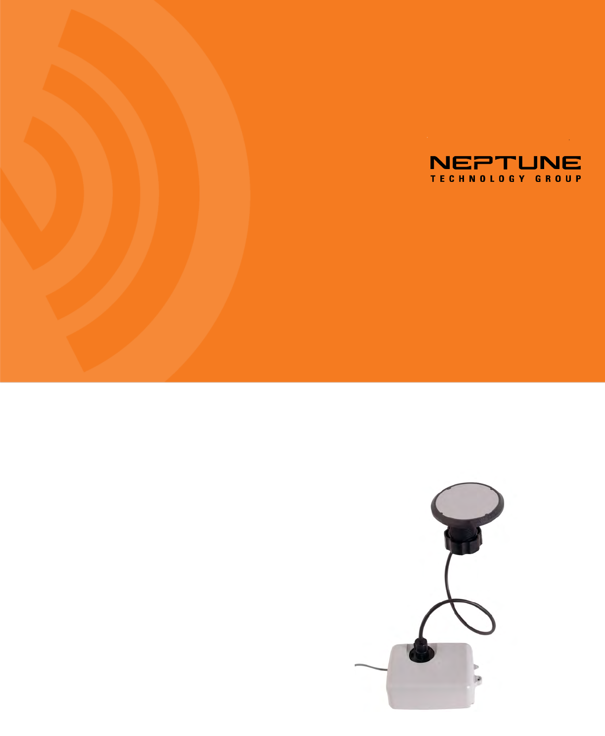
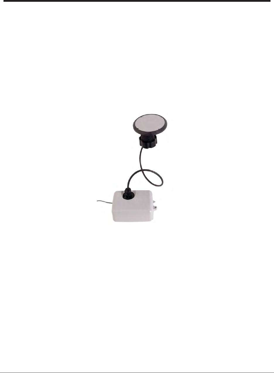
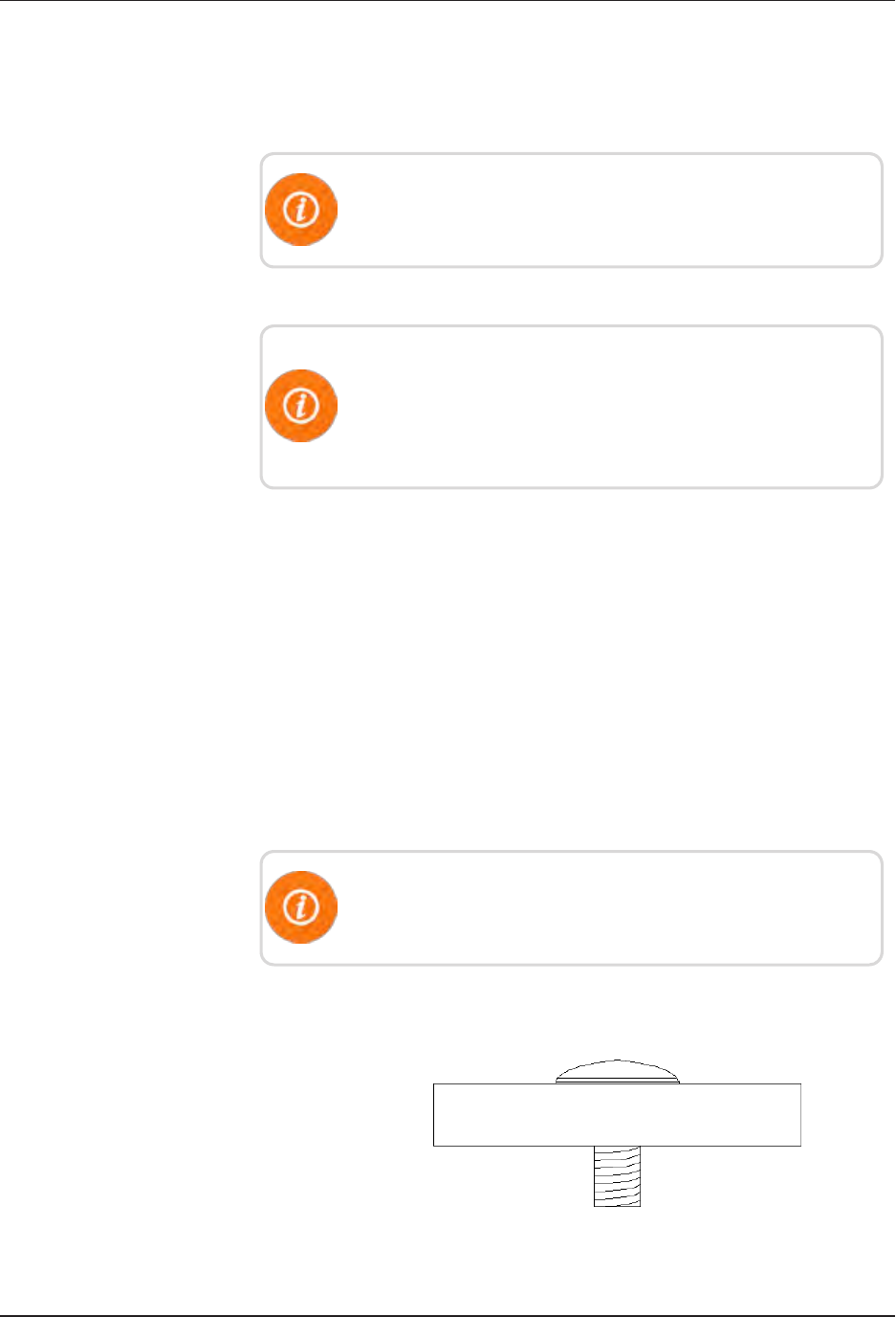
Figure 1 – L900 MIU - Pit 1
Figure 2 – L900 MIU - Pit Dimensions - Front 5
Figure 3 – L900 MIU Pit Dimensions - Side 5
Figure 4 – L900 MIU Pit Antenna 6
Figure 5 – Wiring a Neptune Encoder Register 10
Figure 6 – L900 MIU Color Code for Wires 10
Figure 7 – Cable Threaded Around Strain Relief Posts 11
Figure 8 – Application of the Sealant 11
Figure 9 – Covering the Terminal Screws 12
Figure 10 – L900 MIU Kit 13
Figure 11 – Antenna Placement for Low Traffic Areas 14
Figure 12 – Antenna Placement for High Traffic Areas 15
Figure 13 – Inserting the Antenna into the Pit Lid 16
Figure 14 – Locking Nut on Antenna 16
Figure 15 – Securing the Locking Nut 16
Figure 16 – Installation Completed 17
Figure 17 – Black Thread Guard from Male F-Connector 17
Figure 18 – Seating Washer 17
Figure 19 – Apply Novaguard 18
Figure 20 – Tightening Connector 18
Figure 21 – Gasket and Connector 18
Figure 22 – Scotchloks Connector 19
Figure 23 – Color Code for Wires 19
Figure 24 – Seating Connector Wires 19
Figure 25 – URCrimping Tool 20
Figure 26 – Improper Connections 20
Figure 27 – Three Color Wires Connected 20
Figure 28 – Splice Tube 21
Figure 29 – Gray Wire in Slots 21
Figure 30 – Cover in Place 21
L900 MIU Pit Installation and Maintenance Guide vii

Figure 31 – L900 MIU Attached to Antenna 22
Figure 32 – Magnet Swipe the L900 MIU 22
Figure 33 – HHU Home Screen 25
Figure 34 – N_SIGHTMain Screen 26
Figure 35 – Data Logger Options 26
Figure 36 – Reader ID Input 27
Figure 37 – HHU Time Confirmation 27
Figure 38 – Initialize RF Device 28
Figure 39 – L900 MIU ID Entry 28
Figure 40 – Capture Button 29
Figure 41 – Meter Size Selection 29
Figure 42 – Start Button 30
Figure 43 – Listening for Data 30
Figure 44 – Receiving Data 31
Figure 45 – Graph Button 31
Figure 46 – Examples of Data Logging Graphs 32
Figure 47 – HHU Home Screen 33
Figure 48 – HHU Menu Screen 33
Figure 49 – Off-Cycle Option 34
viii L900 MIU Pit Installation and Maintenance Guide
Figures

Tables
Table 1 – Supported Encoder Maximum Cable Length 4
Table 2 – L900 MIU Pit Environmental Conditions 4
Table 3 – L900 MIU Pit Functional Specification 4
Table 4 – L900 MIU Pit Functional Specification 4
Table 5 – Recommended Tools 7
Table 6 – Recommended Materials 8
Table 7 – Cable Length and Manufacturer 15
Table 8 – Data Logging Graph Legend 32
Table 9 – Examples of Reading Values 36
Table 10 – Available Replacement Parts 36
L900 MIU Pit Installation and Maintenance Guide ix

This page intentionally left blank.
xL900 MIU Pit Installation and Maintenance Guide
Tables
L900 MIU Pit Installation and Maintenance Guide 1
Chapter 1: Product Description
This chapter provides a general description of the L900™ Pit meter interface unit
(subsequently referred to as L900 MIU).
The L900 MIU by Neptune is a compact electronic device that collects meter
reading data from an encoder register. It then transmits the data for collection by
the meter reader. A walk-by handheld unit (HHU), mobile unit, R900®Gateway
collector, or LoRa®(Long Range) collector receives the data and stores it to be
downloaded into the utility billing system for processing.
The L900 MIU is easily installed and operates within a radio frequency (RF)
bandwidth which does not require an operating license. Because the L900 MIU can
be mounted as far as 500 feet from the encoder register, optimum broadcast signal
strength is obtainable, ensuring a high percentage of accurate, one-pass readings.
Figure 1 – L900 MIU - Pit
The L900 MIU meets FCC regulations Part 15.247, allowing higher output power
and greater range. The L900 MIU uses frequency-hopping, spread-spectrum
technology to avoid RF interference and enhanced security. The L900 MIU reads
the encoder registers at 15-minute intervals and transmits a mobile message that
includes the meter reading data and the unique nine-digit L900 MIU ID every 20
seconds. This allows the meter to be read by an HHU or mobile data collection
unit. The L900 MIU also transmits a high power fixed network message every
seven and one-half minutes on an interleaved basis to an R900 Gateway.
In addition to the mobile message that is transmitted every 20 seconds and the
fixed network message that is transmitted every seven and one-half minutes, the
L900 MIU is capable of supporting fixed network using a LoRa network.

The fixed network message that transmits for use on a LoRa network is sent every
three hours.
The L900 MIU is designed to offer advantages to utility organizations of all sizes:
lIncreases meter reading accuracy.
lEliminates infrastructure concerns and the burden of managing collection
devices.
lEliminates “hard-to-read” meters.
lProtects utility liability by increasing meter reader safety.
lRequires no programming.
Product Description
This section gives an overview of the L900 MIU.
L900 MIU Programming
The L900 MIU does NOT require field programming.
RF Protocol Error Detection
The RF protocol is comprised of a header, data packet, and an error detection
mechanism that reduces the erroneous data.
RF Frequency Control Algorithm
The L900 MIU’s frequency-hopping, spread-spectrum has a sequence of at least 50
different channels for transmitting data. Associated with the 50 channels are 50
frequencies that can be pre-selected in a pseudo random manner. These 50
frequencies are coded into the software.
The L900 MIU avoids 914 MHz to prevent collision with the Advantage probe.
RF Transmission Period and Randomness
The random period generation uses the same random seed created for the channel
definition to generate the transmission randomness. The randomness algorithm is
defined so that no two consecutive transmissions from two L900 MIUs interfere
with one another.
Low Battery RF Emissions
The L900 MIU stops RF transmissions when the battery discharges below the
normal operating voltage.
2 L900 MIU Pit Installation and Maintenance Guide
Chapter 1: Product Description

L900 MIU Pit Installation and Maintenance Guide 3
Chapter 2: L900 Specifications
This chapter provides you with the specifications for the L900 MIU.
Electrical Specifications
The power is supplied by a Lithium battery.
Transmitter Specifications
This section provides information on transmitter specifications.
Transmit Period lEvery 20 seconds - R900®standard mobile
message
lEvery seven and one-half minutes - R900 standard,
high power, fixed network message
lEvery three hours - LoRa fixed network message
Encoder Reading Encoder registers every 15 minutes
Transmitter
Channels
50
Channel Frequency 902 - 928 MHz
Output Power Meets FCC Part 15.247
FCC Verification Part 15.109
Encoder Register Interface
This section provides information on the maximum cable lengths required for
different registers. See the table on the following page.

Neptune ARB®V1300 feet (91 meters)
Neptune ProRead™ and E-CODER®500 feet (152 meters)
Sensus Protocol registers 200 feet (61 meters)
1Meets manufacturer's published specifications for wire length between encoder
and remote receptacle. The length is based on solid three conductor wire, 22
AWG.
Table 1 – Supported Encoder Maximum Cable Length
Specifications - L900 MIU Pit
Environmental Conditions
This section provides the environmental specifications for the
L900 MIU.
Operating Temperature -22° to 149°F (-30° to 65°C)
Storage Temperature -40° to 158°F (-40° to 70°C)
Operating Humidity 0 to 100% Condensing
Table 2 – L900 MIU Pit Environmental Conditions
Functional Conditions
This section provides the functional specification of the L900
MIU.
Register Reading Eight digits
L900 MIU ID Nine digits
Table 3 – L900 MIU Pit Functional Specification
Dimensions and Weight
This section provides the dimensions and weight of the L900
MIU.
Dimensions Refer to Figure 3 and Figure 4
Weight 1.0 lbs. (454 grams)
Table 4 – L900 MIU Pit Functional Specification
4 L900 MIU Pit Installation and Maintenance Guide
Chapter 2: L900 Specifications
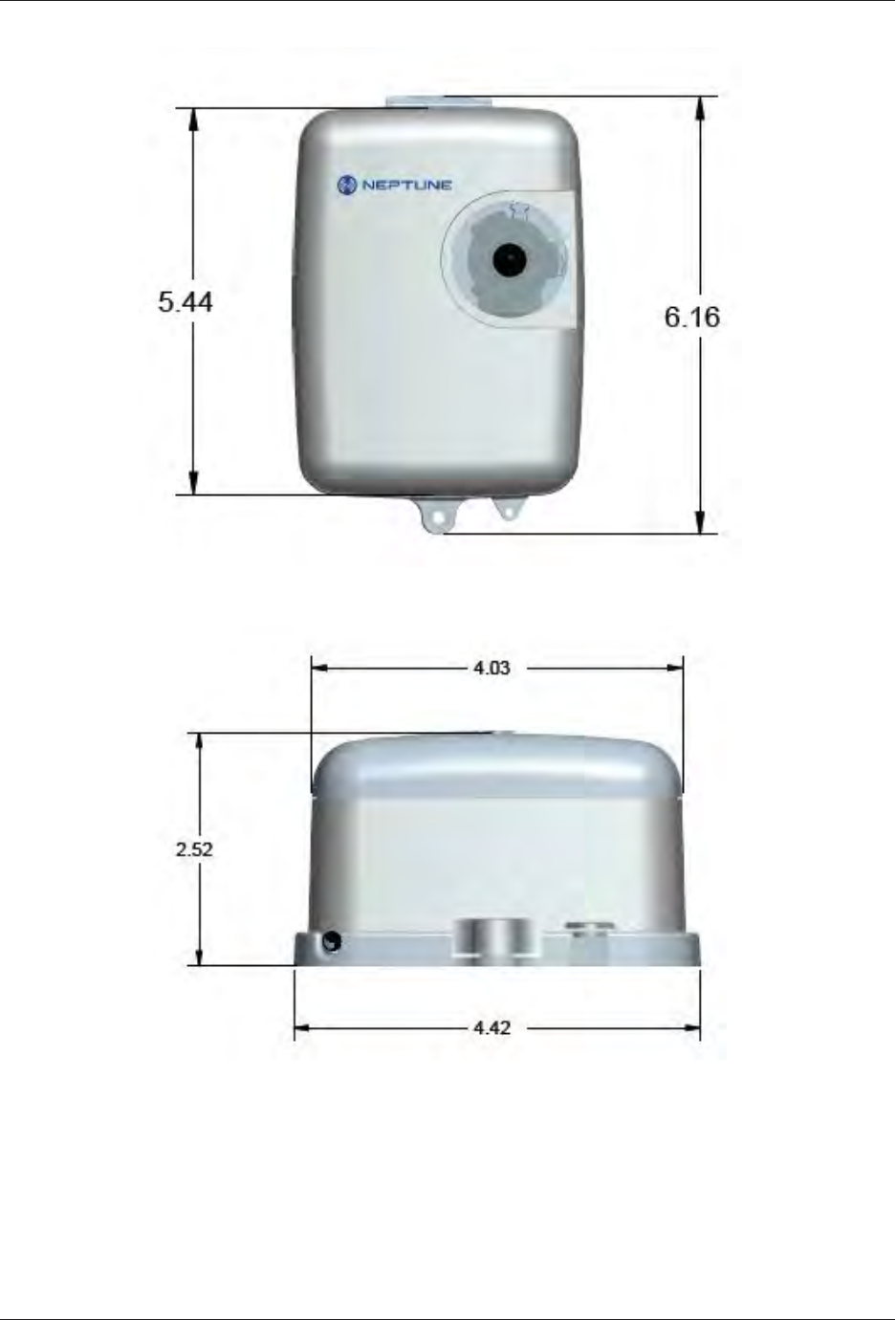
Figure 2 – L900 MIU - Pit Dimensions - Front
Figure 3 – L900 MIU Pit Dimensions - Side
L900 MIU Pit Installation and Maintenance Guide 5
Chapter 2: L900 Specifications
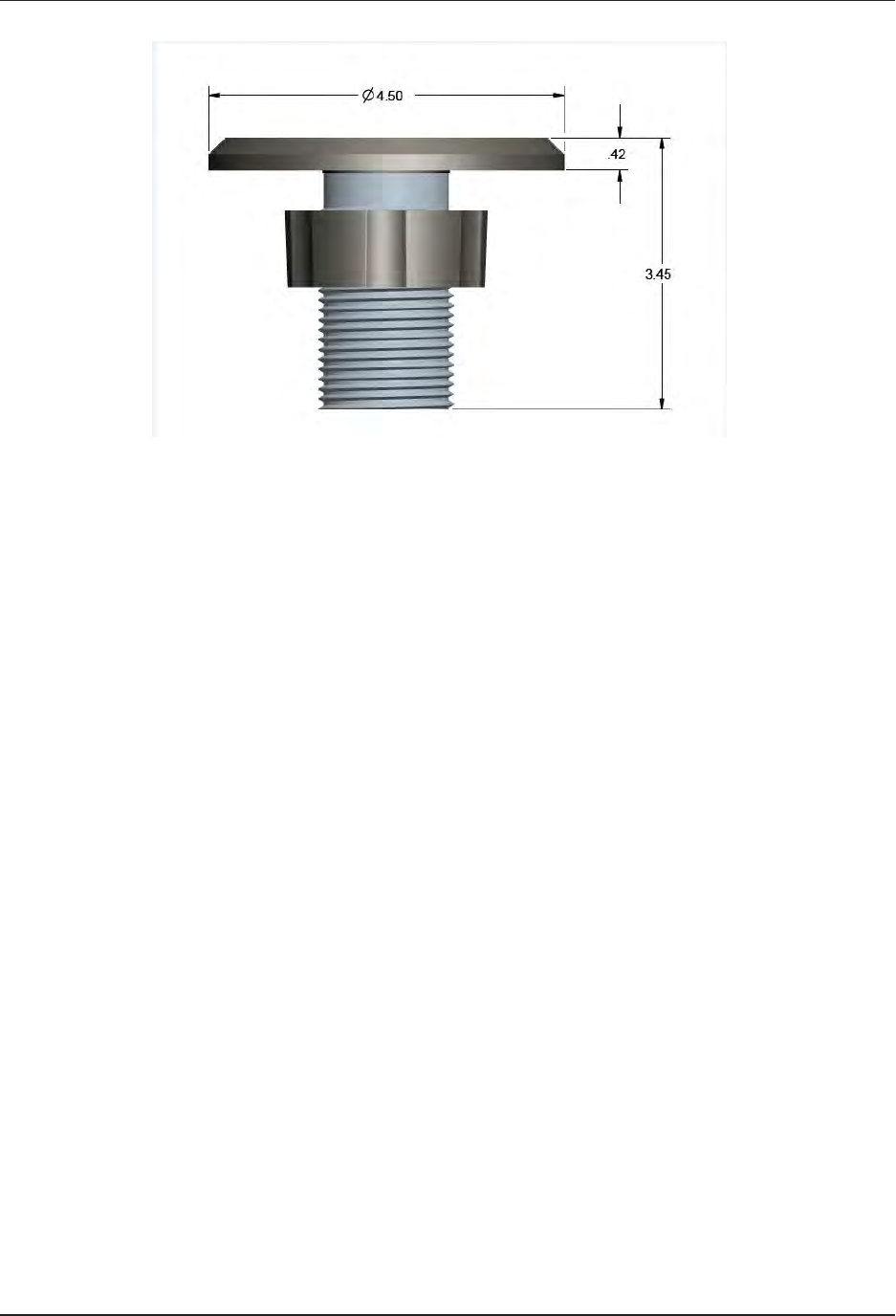
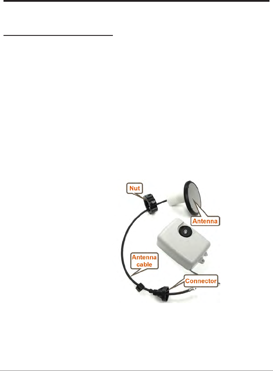
Figure 4 – L900 MIU Pit Antenna
6 L900 MIU Pit Installation and Maintenance Guide
Chapter 2: L900 Specifications

L900 MIU Pit Installation and Maintenance Guide 7
Chapter 3: General Installation Guidelines
This chapter describes tools, materials, and general installation guidelines for the
L900 MIU.
Tools and Materials
Table 5 below and Table 6 on the next page show the recommended tools and
materials you need to successfully install the L900 MIU.
It is possible that some items do not apply to your specific installation, or the
list does not contain all required tools or materials.
Item Description/Recommendations Use
Took Kit Contains standard tools including:
lAssorted screwdrivers
lNeedle-nose pliers
lWire stripper
lDiagonal cutters
lElectrician's knife
lHammer
lCrimping tool (Part # 5500-158)
Performs various installation procedures.
Magnet 6 lb. force (Part # 12287-001) Magnet swipe the L900 MIU.
Table 5 – Recommended Tools

Item Description/Recommendation Use
Cable Solid 3 Conductor #22 AWG
(black/green/red) Part # 6431-
352
Connect L900 MIU to encoder register.
Moisture Protection
Compound
Novaguard sealant
Part# 96018-072
Cover exposed wires and terminal screws on
register and L900 MIU.
Scotchloks Part# 8138-125 Connect replacement pit L900 MIU to
encoder register.
Site Work Order Documentation provided by your
utility
Receive and record information about the
work site.
Table 6 – Recommended Materials
Safety and Preliminary Checks
Observe the following safety and preliminary checks before and
during each installation.
lVerify that you are at the location specified on the site work
order.
lVerify that the site is safe for you and your equipment.
lNotify the customer of your presence and tell them you need
access to the water meter.
lWrite in the ID number(s) of the L900 MIU you are about to
install, if the site work order does not have an L900 MIU ID
number.
lVerify that the ID number(s) matches the IDnumber(s) on the
L900 MIU you are about to install, if the site work order
already has a L900 MIU ID number.
Verifying/Preparing the Encoder Register
The L900 MIU is designed for use with the following encoder
registers:
lARB V
lProRead
8 L900 MIU Pit Installation and Maintenance Guide
Chapter 3: General Installation Guidelines

lProRead AutoDetect
lE-CODER
lMACH 10
lCompetitive registers using Sensus which include: Sensus
ECRIII, ICE, iPerl, OMNI, and electronic registers; also
Hersey/Mueller Translator, Badger ADE, and HR ELCD
Before installing an L900 MIU, the encoder register must be
correctly wired and/or programmed to work with the L900 MIU.
E-CODER registers do not require programming.
When a ProRead encoder register is used, the non-
AutoDetect ProRead register must be programmed for three-
wire mode.
If connecting the L900 MIU to a new ProRead encoder register, or
if a three-conductor cable is already connected to a ProRead
encoder register, ensure that the ProRead register is programmed
for three-wire mode using the ProRead programmer and its
RF/L900 MIU 6, 8, or 10 ID TDI format. This can be
accomplished through the ProRead receptacle before it is
removed.
Installation of a Register (Non Pre-Wired or Potted Only)
Before wiring the pit encoder register, consider the following.
1. Make sure the cable is long enough. When the installation is
complete, the pit lid can be removed easily without straining
the cable.
2. Use only 22 AWG cable to make the connection from the
encoder register to the L900 MIU.
3. Remove the terminal screw from the encoder register.
4. Strip ¾-inch insulation from the cable jacket, leaving only the
three insulated wires.
5. Take precautions not to nick or cut the insulation on the three
wires, strip off ½-inch of insulation from each of the three
wires.
L900 MIU Pit Installation and Maintenance Guide 9
Chapter 3: General Installation Guidelines
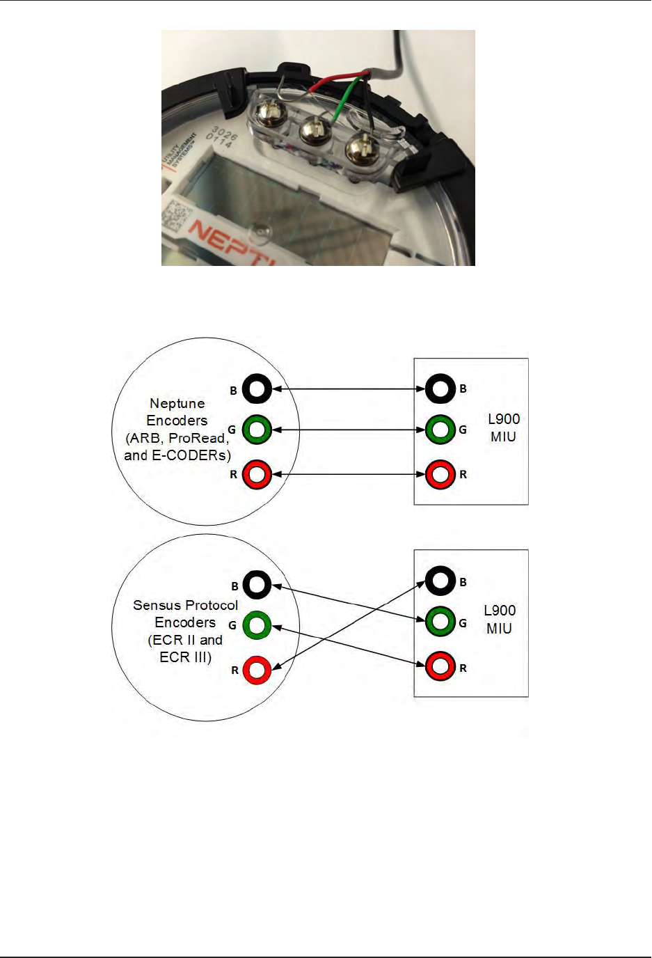
Figure 5 – Wiring a Neptune Encoder Register
Figure 6 – L900 MIU Color Code for Wires
6. If required, connect the three conductor wires to the encoder
register's terminal per the manufacturer's instructions. See
Figure 5 and Figure 6.
10 L900 MIU Pit Installation and Maintenance Guide
Chapter 3: General Installation Guidelines
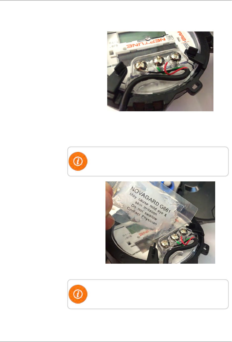
7. Thread the cable around the strain relief posts of the encoder.
See Figure 7.
Figure 7 – Cable Threaded Around Strain Relief Posts
8. Apply sealant liberally and ensure that it encapsulates the
terminal screws and exposed wires. See Figure 8.
Neptune requires Novaguard G661 sealant or Dow Corning
compound 4.
Figure 8 – Application of the Sealant
Any leak point can cause a reading failure in a submerged
meter setting.
L900 MIU Pit Installation and Maintenance Guide 11
Chapter 3: General Installation Guidelines
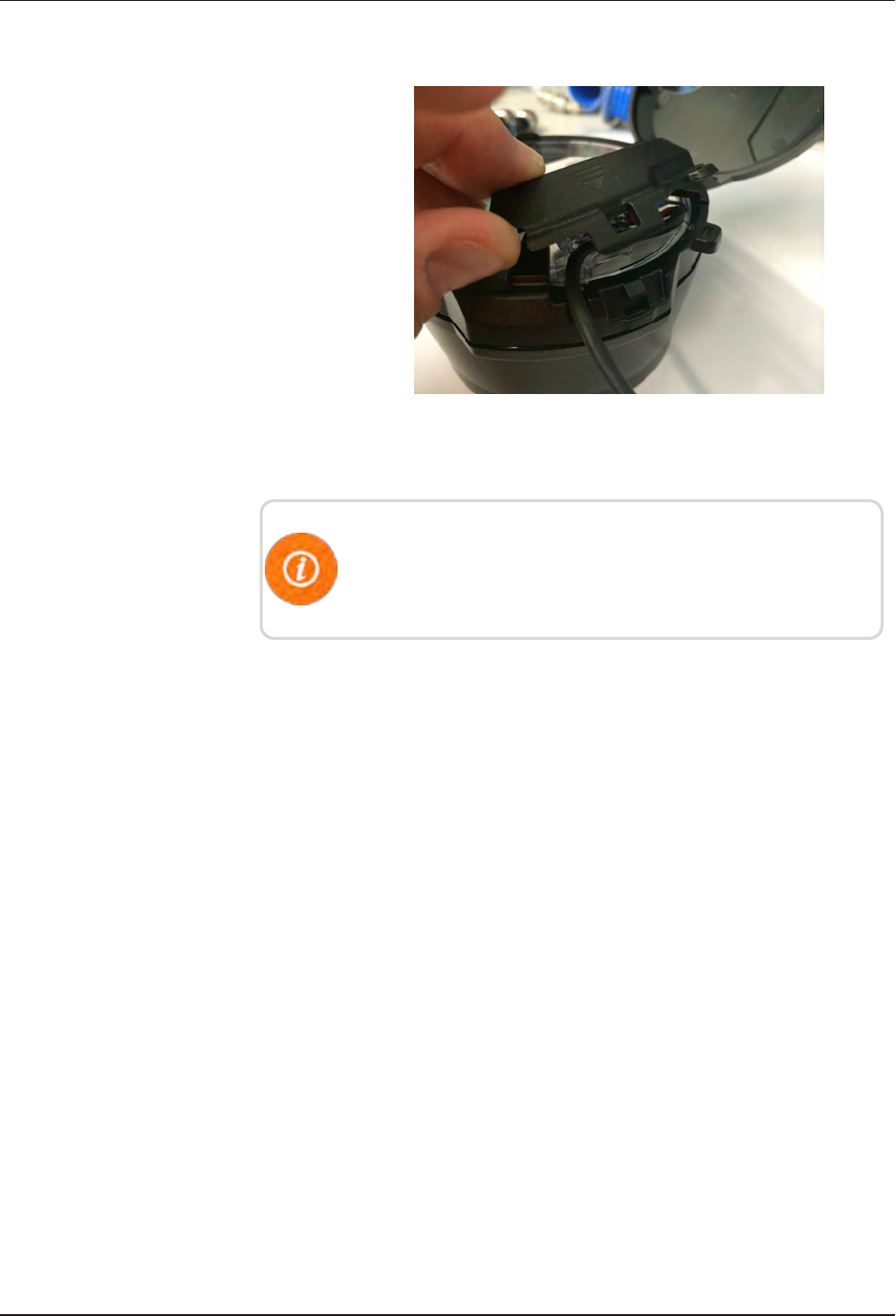
9. Snap the cover onto the encoder register. See Figure 9 below.
Figure 9 – Covering the Terminal Screws
10. Run the cable to the L900 MIUand fasten it securely.
Do not exceed maximum cable lengths as defined in Table 1
on page 4. If the encoder register is prewired and potted, use
Scotchloks for connecting the register to the L900 MIU.
12 L900 MIU Pit Installation and Maintenance Guide
Chapter 3: General Installation Guidelines
L900 MIU Pit Installation and Maintenance Guide 13
Chapter 4: Pit Installation
This chapter describes storage and unpacking instructions, preliminary tests, tools,
materials, site selection, and pit installation of the L900 MIU.
Prior to Installation
Storage
Upon receipt, inspect shipping containers and contents for damage prior to storage.
After the inspection is complete, store the cartons in a clean, dry environment.
Keep in mind that the L900 MIU has an internal battery. Storage for more than one
year can affect product life. Be sure to use a first-in first-out inventory control
system. See "Environmental Conditions" on page4
Unpacking
As with all precision electronic instruments, the L900 MIU must be handled
carefully; however, no additional special handling is required.
After unpacking the L900 MIU, inspect it for damage. If the L900 MIU appears to
be damaged or proves to be defective upon installation, notify your Neptune sales
representative. If one or more items requires reshipment, use the original cardboard
box and packing material.
Figure 10 – L900 MIU Kit
Tools and Materials
Table 5 on page 7 and Table 6 on page 8 show the recommended
tools and materials you need to successfully install the L900
MIU.
Some items may not apply to your specific installation, or the
list may not contain all required tools or materials.
Site Selection
Always follow your company's safety practices and
installation guidelines when installing an L900 MIU. Never
perform an installation during a lightening storm or under
excessively wet conditions.
Installation and operation in moderate temperatures increase
reliability and product life. See "L900 MIU Pit Environmental
Conditions" on page4.
Follow these guidelines when selecting a location to install the
L900 MIU.
lFor best results, select a location where there is no chance that
another object can be set over the antenna.
lAvoid installing the L900 MIU behind metal fences or walls.
lMake sure the pit location gives adequate room for installing
both the L900 MIU and the pit antenna.
For maximum performance, the flange of the pit antenna
needs to be located above the pit lid.
lFor maximum performance, Neptune recommends that pit
antennas be installed above the lid as illustrated in Figure 11.
Figure 11 – Antenna Placement for Low Traffic Areas
14 L900 MIU Pit Installation and Maintenance Guide
Chapter 4: Pit Installation

lWhen installing in a high traffic area, Neptune recommends
that the dome of the antenna be recessed in the pit lid as
shown in Figure 12.
lRecessing the installation reduces the range of the antenna.
Figure 12 – Antenna Placement for High Traffic Areas
lFor best results, Neptune recommends installing the L900 MIU
in a location that provides a direct line of site to the path of
the meter reader.
lAlthough the L900 MIU has a cable already attached (2 feet
or 6 feet), some installations can require additional cable. In
these cases, the maximum cable length between the encoder
register and L900 MIU depends on the register's manufacturer
and model. Refer to Table 7 for maximum cable lengths.
Encoder Register Maximum Cable Length
Neptune ARB V* 300 feet (91 meters)
Neptune ProRead / E-CODER 500 feet (152 meters)
Sensus Protocol Register 200 feet (61 meters)
* Meets manufacturer's published specification for wire length
between encoder and remote receptacle.
Table 7 – Cable Length and Manufacturer
L900 MIU Pit Installation
The following section describes how to install a single L900 MIU
in a pit location.
L900 MIU Pit Installation and Maintenance Guide 15
Chapter 4: Pit Installation
Select a location for the L900 MIU that meets the
recommendations in "Site Selection" on page14.
Installing the Antenna
Figure 13 – Inserting the Antenna
into the Pit Lid
1. Insert the antenna cable and housing through the 1¾-
inch hole in the meter pit lid. See Figure 13.
Figure 14 – Locking Nut on Antenna
2. Thread the locking nut onto the antenna (unthreaded
end towards lid). See Figure 14.
Figure 15 – Securing the Locking Nut
3. Hand tighten the nut securely to the lid. See Figure 15.
16 L900 MIU Pit Installation and Maintenance Guide
Chapter 4: Pit Installation
Figure 16 – Installation Completed
Figure 16 shows a completed installation of the antenna.
Begin the Installation
Complete the following steps to install the L900 MIU in a pit.
Figure 17 – Black Thread Guard from
Male F-Connector
1. Remove black plastic thread protector cap from the
male F-connector on the L900 MIU.
Figure 18 – Seating Washer
2. Place the flat black rubber washer around the male F-
connector on the L900 MIU as shown in Figure 18.
L900 MIU Pit Installation and Maintenance Guide 17
Chapter 4: Pit Installation
Figure 19 – Apply Novaguard
3. Apply a coating of Novaguard around the base of the
F-connector and on the flat rubber washer. See Figure
19.
4. Using a torque wrench, connect the coaxial cable
connector to the F-connector on the L900
MIU/housing, tightening it to 15 inch-pounds.
Antenna connection should have Novaguard applied
inside the connector.
Threading the F-Connector
Complete the following steps to thread the F-connector.
Figure 20 – Tightening Connector
1. Make sure the flat washer is properly seated, and then
connect the black plastic cable connector housing to
the three-lobed plastic latch plate.
2. Tighten the connector by making a ¼ turn to the right
as shown in Figure 20.
3. Slide the black cone-shaped gasket down the cable
until it seats against the connector housing.
Figure 21 – Gasket and Connector
4. Slide the black plastic female-threaded connector down
the coax cable.
5. Seat on top of cone-shaped rubber gasket and thread
onto the three-lobed plastic latch plate as shown in
Figure 21.
6. Finger-tighten the connector to depress cone-shaped
rubber gasket.
This seals the coax cable from moisture intrusion.
18 L900 MIU Pit Installation and Maintenance Guide
Chapter 4: Pit Installation
Installing the Scotchloks
Complete the following steps to install the Scotchloks.
Figure 22 – Scotchloks Connector
1. Complete steps outlined in "L900 MIU Pit Installation"
on page15 to install the L900 MIU through the lid.
2. Use 3MScotchloks type UR connector to connect the
L900 MIU wires to the encoder wires.
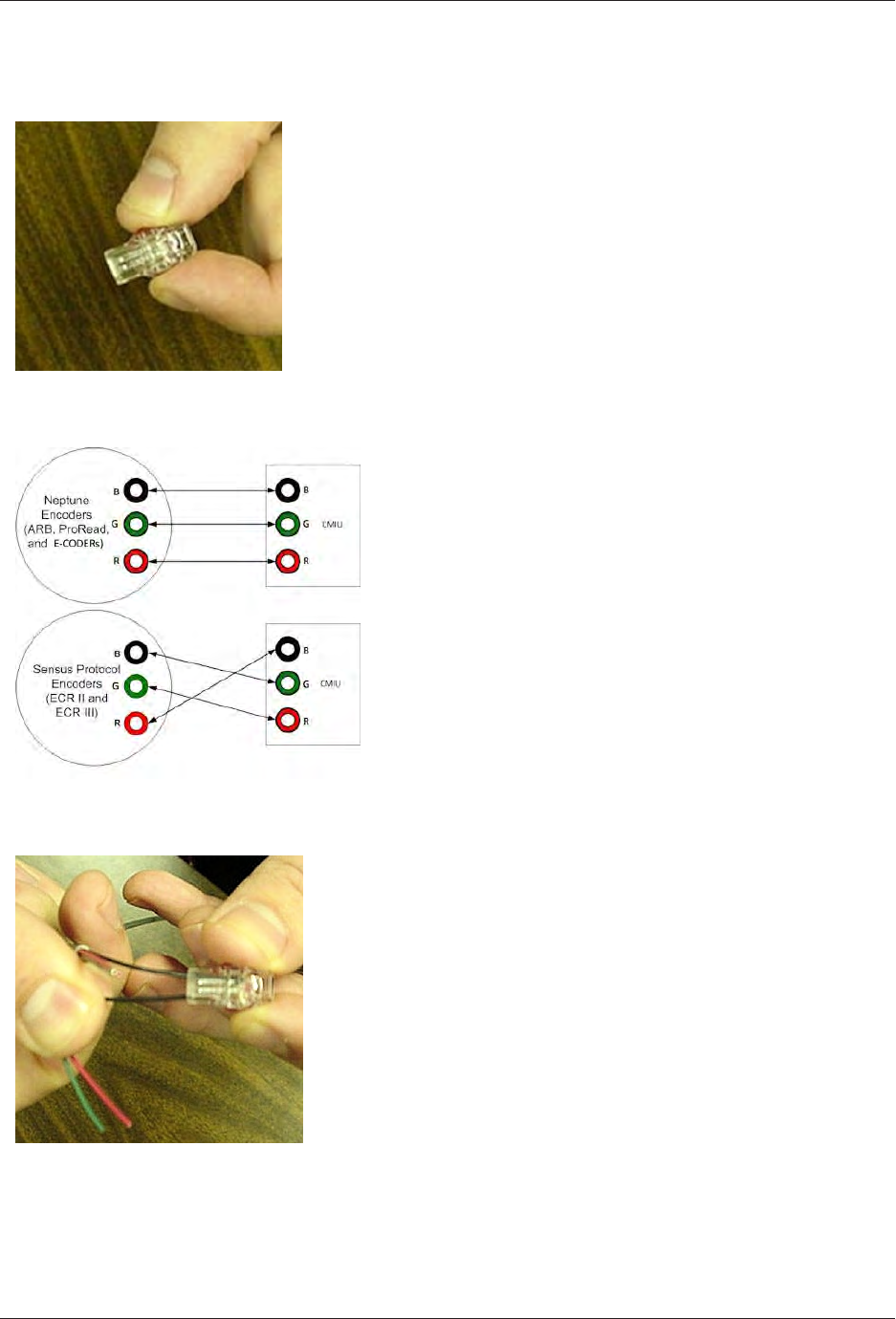
3. Hold the Scotchloks connector between the index
finger and thumb with the red cap facing down. See
Figure 22.
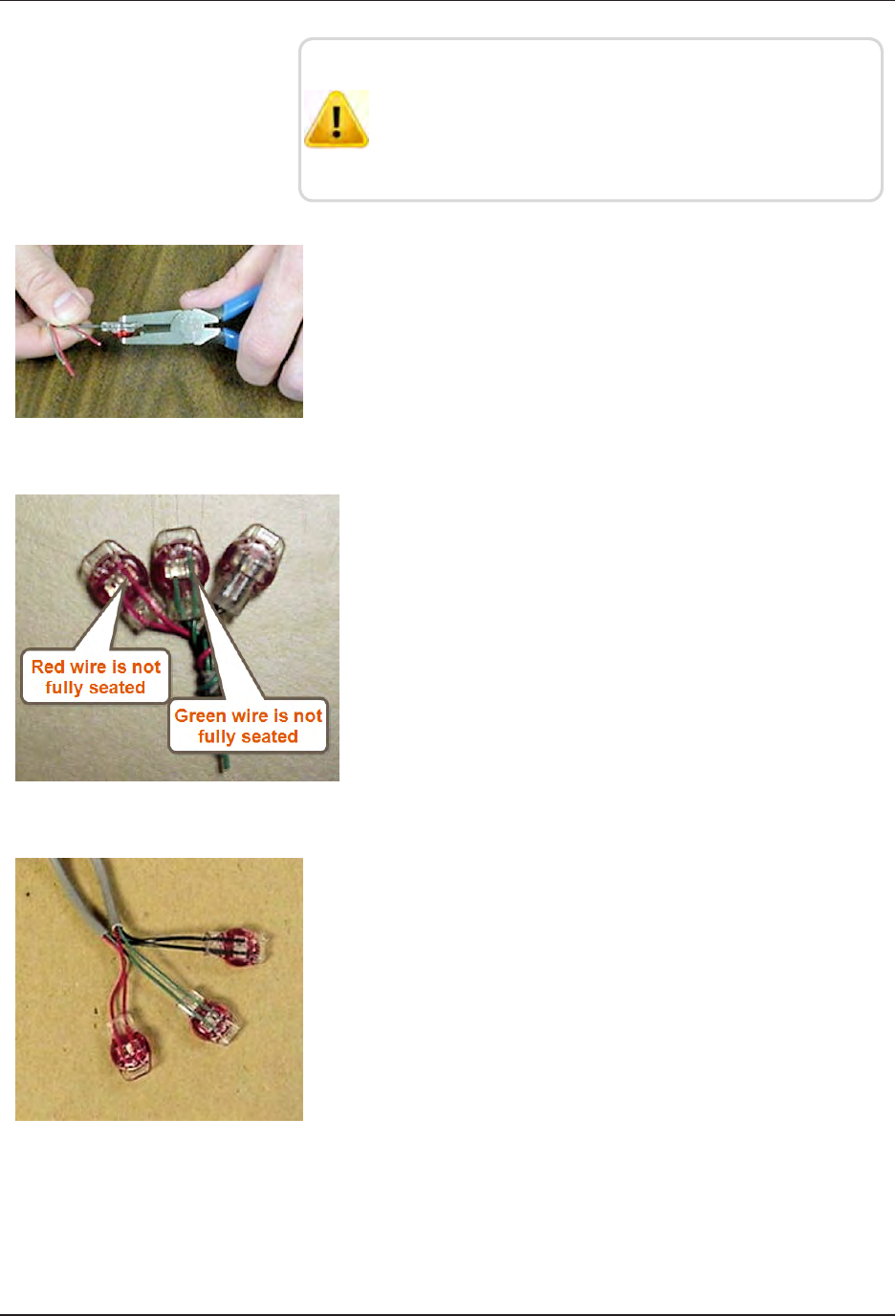
Figure 23 – Color Code for Wires
4. Pair the wires according to the color diagram. See Figure
23.
Figure 24 – Seating Connector Wires
5. Take a non-stripped black wire from the pigtail and a
non-stripped black wire from the L900 MIU and insert
wires into the Scotchloks connector until fully seated
in the connector. See Figure 24.
L900 MIU Pit Installation and Maintenance Guide 19
Chapter 4: Pit Installation
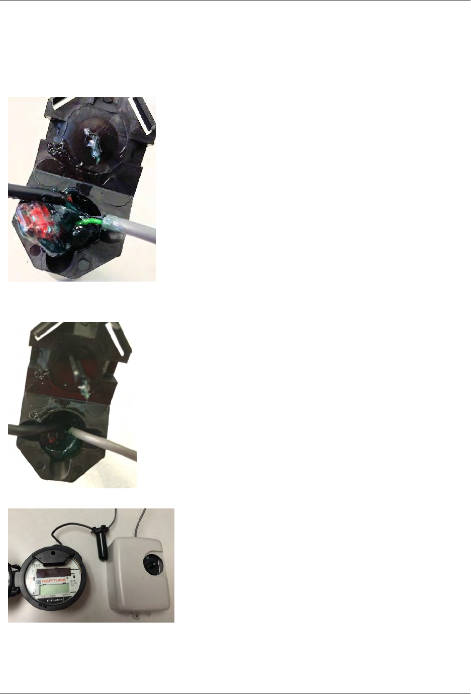
Do not strip colored insulation from wires, or strip and
twist bare wires prior to inserting in a connector. Insert
insulated colored wires directly into the Scotchloks
connector.
Figure 25 – URCrimping Tool
6. Place the connector (red cap side down) between the
jaws of the UR crimping tool as shown in Figure 25.
Figure 26 – Improper Connections
7. Check to ensure the wires are still fully seated before
crimping the connector. Figure 26 illustrates improper
connections due to wires not fully seated.
Figure 27 – Three Color Wires
Connected
8. Squeeze the connector firmly with the proper crimping
tool until you hear a pop and gel leaks out of the end of
the connector.
9. Repeat steps two through seven for each color wire. See
Figure 27.
10. After all three color wires have been connected, go to
"Testing the Installation" on page1 to ensure proper
connections and the L900 MIU is functioning properly.
20 L900 MIU Pit Installation and Maintenance Guide
Chapter 4: Pit Installation
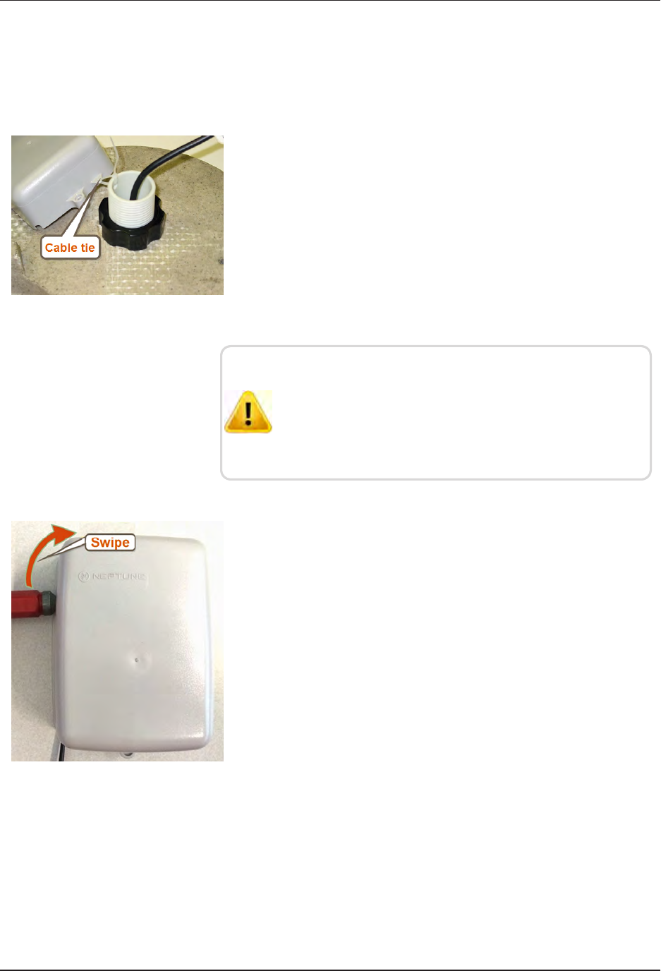
Connecting the Splice Tube
To finish the installation of the Scotchloks, complete the
following steps to install the connector king splice tube.
Figure 28 – Splice Tube
1. Take all three connected Scotchloks and push into the
splice tube until fully encapsulated by the silicone
grease. See Figure 28
Figure 29 – Gray Wire in Slots
2. Separate each gray wire and place in the slots on each
side as shown in Figure 29.
Figure 30 – Cover in Place
3. Snap cover closed to finish the installation as shown in
Figure 30.
L900 MIU Pit Installation and Maintenance Guide 21
Chapter 4: Pit Installation
Tying the Cable and Magnet Swiping the L900 MIU
Complete the following steps to tie the cable and magnet swipe
the .L900 MIU.
1. Place the L900 MIU in the pit location using the
following suggestions.
lIn a shallow pit application, you can place the L900
MIU beside the meter.
lIn deep pit applications, use a cable tie to suspend the
L900 MIU from the antenna shaft, as shown in Figure
31.
Figure 31 – L900 MIU Attached to Antenna
Be careful not to lodge the L900 MIU between the meter
box and any components inside the box.
Make sure the L900 MIU is placed in such a way that it
does not lodge itself when the pit lid is removed.
Figure 32 – Magnet Swipe the L900
MIU
2. Swipe the L900 MIU with a magnet.
lPosition the magnet against the left side of the L900
MIU directly in line with the Neptune logo.
lMove the magnet up and over the top left corner of
the L900 MIU. See Figure 32.
22 L900 MIU Pit Installation and Maintenance Guide
Chapter 4: Pit Installation
Testing the Installation
If the L900 MIU is connected to an E-CODER register or another
register with an eight-digit output, the L900 MIU will transmit an
eight-digit read. For example, read 12345678 (E-CODER or other
eight-digit register output).
To test the installation, complete the following steps.
To avoid RF signal saturation of the HHU, position yourself at
least two to three feet from the L900 MIU.
1. Power up the HHU test device and start the testing programs
provided.
2. When the L900 MIU is installed correctly, its ID number(s)
and meter reading(s) appear on the display of the HHU. Verify
the correct meter reading(s) by comparing it to the meter’s dial.
If the reading(s) is the same, proceed to the next section.
3. If a meter reading does not appear on the HHU display, or the
meter reading in the HHU display is not the same as the
reading on the meter’s dial:
lMagnet swipe the L900 MIU using the magnet.
lVerify all electrical connections.
lTest the installation again.
4. If a ProRead encoder register is used:
lEnsure the unit is programmed in three-wire mode.
lVerify all electrical connections.
lMagnet swipe the L900 MIU. (See Step 1.)
If a problem still exists, contact your Neptune sales
representative.
L900 MIU Pit Installation and Maintenance Guide 23
Chapter 4: Pit Installation

This page intentionally left blank.
Chapter 4: Pit Installation
24 L900 MIU Pit Installation and Maintenance Guide
L900 MIU Pit Installation and Maintenance Guide 25
Chapter 5: Data Logging Extraction
About Data Logging
The L900 MIU is capable of storing interval data for data logging. The L900 MIU
is activated using the Trimble®Nomad®and R900®Belt Clip Transceiver
(R900 BCT) and is explained in more detail in the following section.
The L900 MIU stores consumption in hourly intervals for a rolling total of 96 days.
This is equal to 2,304 hourly intervals of consumption. The data logging data is
extracted through RF activation. The RF activation allows the utility workers to
visit the location and extract the data without physically interacting with the meter
itself. This limits the worker’s exposure to animals or other dangerous situations.
The extraction process, once started, takes approximately 30 seconds. The
activation is done through the HHU connected to the R900 BCT via Bluetooth.
The activation signal is sent by the R900 BCT to the L900 MIU which in turn
sends the data intervals to the R900 BCT and are saved in the HHU.
Accessing Data Logging
Complete the following steps for data logging.
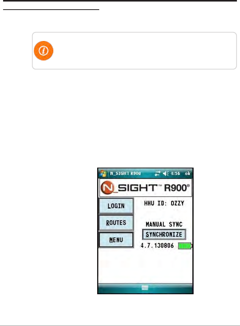
1. From the host software home screen on the HHU, click MENU. See Figure 46.
Figure 33 – HHU Home Screen
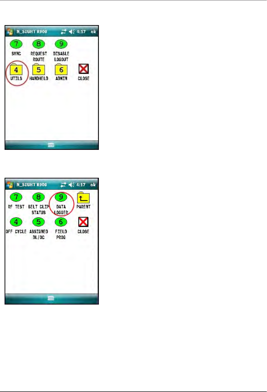
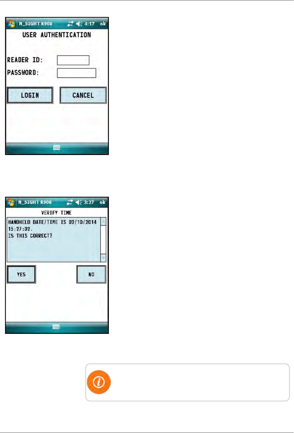
Figure 36 – Reader ID Input
4. Type your reader ID and password (if applicable) for the
host software. Click LOGIN. See Figure 36.
Initializing the Data Logger
Figure 37 – HHU Time
Confirmation
1. Verify the time is correct, and click YES. See Figure 37.
The HHU must be synchronized prior to data logging in order
to set the clock.
L900 MIU Pit Installation and Maintenance Guide 27
Chapter 5: Data Logging Extraction
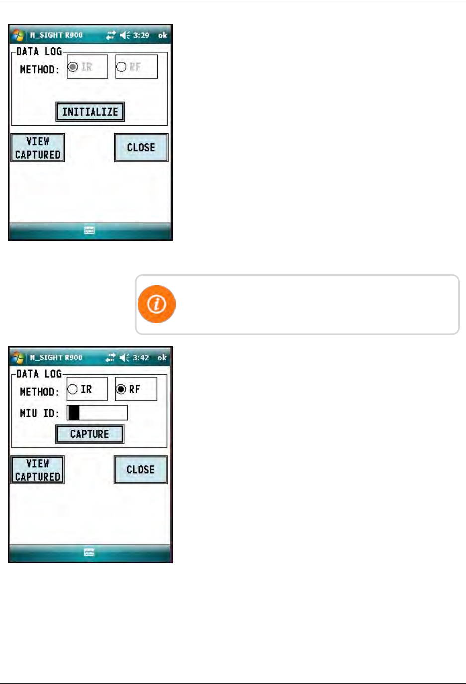
Figure 38 – Initialize RF Device
2. The Initialize Device screen appears if you are not
connected or you are not in range of your R900 BCT. Click
INITIALIZE. See Figure 38.
You must initialize the R900 BCT each time you attempt to
data log.
Figure 39 – L900 MIU ID Entry
3. Select RF and type the L900 MIU ID. See Figure 39.
28 L900 MIU Pit Installation and Maintenance Guide
Chapter 5: Data Logging Extraction
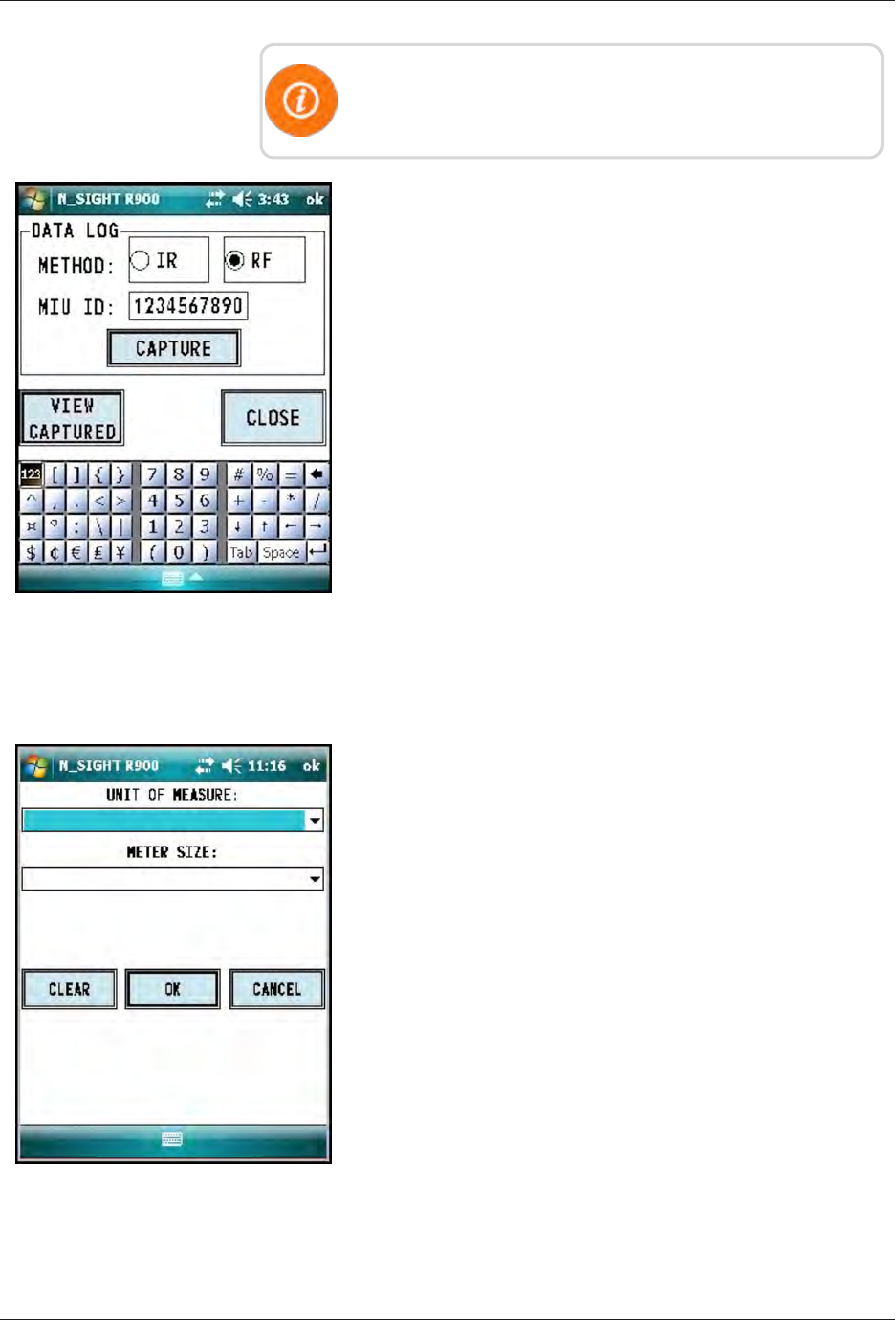
You can type the L900 MIU ID with the number pad keys or
expand the on-screen keyboard.
Figure 40 – Capture Button
4. After you type the L900 MIU ID, click CAPTURE. See
Figure 40.
Figure 41 – Meter Size Selection
5. You are prompted to provide meter size and unit of measure.
You can type this information now and click OK or after
the data logging has completed. See Figure 41.
L900 MIU Pit Installation and Maintenance Guide 29
Chapter 5: Data Logging Extraction
Initiating RF-Activated Data Logging
Complete the following steps to initiate RF-activiated data
logging.
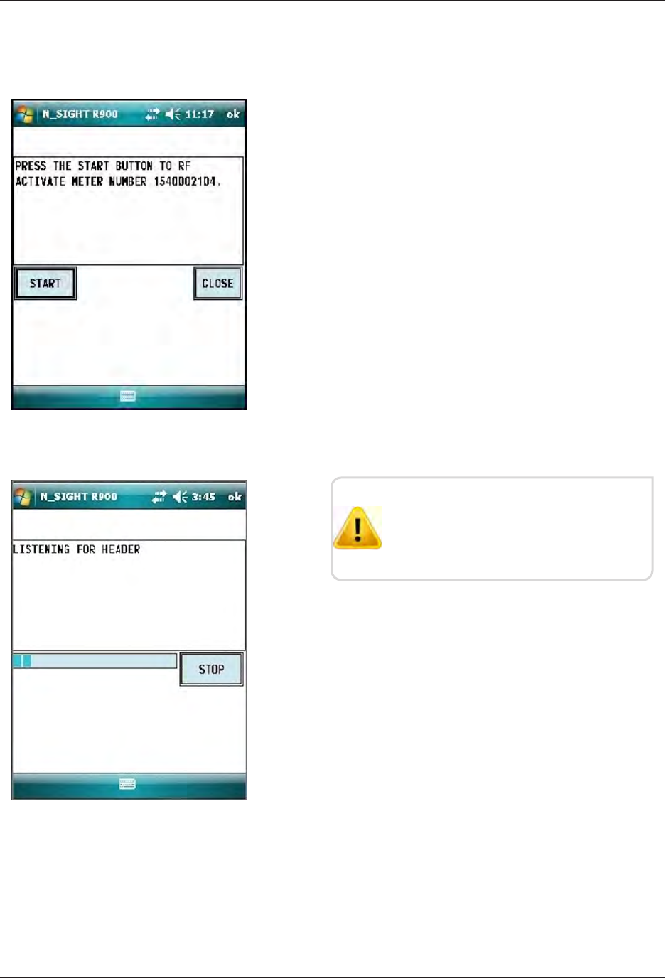
Figure 42 – Start Button
1. Click START to initiate RF-activated data logging. See
Figure 42.
Figure 43 – Listening for Data
The R900 BCT activates the L900 MIU
and listens for the data logger to start
transmitting. See Figure 43.
30 L900 MIU Pit Installation and Maintenance Guide
Chapter 5: Data Logging Extraction
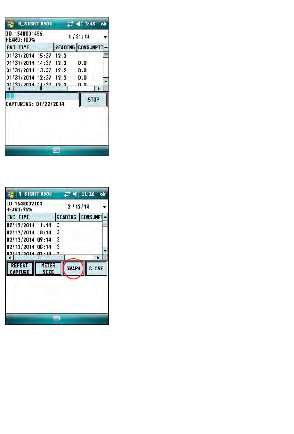
Figure 44 – Receiving Data
The data appears on the screen. See Figure 12.
Figure 45 – Graph Button
1. After the data logging process is completed, choose the
meter size (see Step 5 on page 33).
2. Click GRAPH (see Figure 43) to display the data in a
graph. Examples of graphs are shown in Figure 46 on the
next page.
The HHU processes and saves the data. After closing the
data logging screen, the unit performs a backup.
Sample Data Logging Graphs
The following are two examples of the graphs that can be produced with data
logging.
L900 MIU Pit Installation and Maintenance Guide 31
Chapter 5: Data Logging Extraction
Figure 46 – Examples of Data Logging Graphs
Color Code Description
1 red Intermittent Leak
2 red Continuous Leak
1 gray Minor Backflow
2 gray Major Backflow
Blue bars No Flags
Red bars Leak
Gray bars * Backflow
* If the Backflow flag and the Leak flag appear at the same time,
Backflow (Gray bars) has precedence over Leak.
Table 8 – Data Logging Graph Legend
32 L900 MIU Pit Installation and Maintenance Guide
Chapter 5: Data Logging Extraction
Off-Cycle Data Extraction
Off-cycle reads are 96 days of daily reads. These are to allow
utilities to retrieve move-out reads or monitor vacant usage to
prevent theft.
To navigate to off cycle, complete the following steps.
Figure 47 – HHU Home Screen
1. From the host software home screen on the HHU, click
MENU. See Figure 47.
Figure 48 – HHU Menu Screen
2. From the HHU Menu screen, click UTILS (option 4). See
Figure 48.
L900 MIU Pit Installation and Maintenance Guide 33
Chapter 5: Data Logging Extraction
Figure 49 – Off-Cycle Option
3. Click OFF CYCLE (option 4). See Figure 49.
4. Type the read ID and/or the password.
5. Click LOGIN.
6. Confirm date and time are correct.
7. Click YES.
R900 Belt Clip Transceiver
To pair with R900 BCT, complete the following steps.
1. Change date if you have a specific day to target.
2. Click INITALIZE to pair with R900 BCT.
3. Type the L900 MIU ID.
4. Click CAPTURE.
The reads come in just like the data logger reads. The data
logger has 96 days of hourly reads and off cycle has 96 days
of daily reads.
34 L900 MIU Pit Installation and Maintenance Guide
Chapter 5: Data Logging Extraction
L900 MIU Pit Installation and Maintenance Guide 35
Chapter 6: Maintenance and Troubleshooting
This chapter takes you through maintenance and troubleshooting procedures for the
L900 MIU.
Six- and Four-Wheel Encoders
Six-Wheel Encoders Normal Operation
If the odometer reads 123456, the display should show 1 2 3 4 5 5 0 0.
The sixth digit displayed is a five if the last digit on the odometer is five through
nine. The sixth digit is a zero if the last digit on the odometer is zero through
four. The L900 MIU adds an additional two zeros on the end to provide an eight-
digit reading to the host software.
Four-Wheel Encoders Normal Operation
If the odometer reads 1234, the display should show 1 2 3 4 0 0 0 0.
The L900 MIU adds an additional four zeros on the end to provide an eight-digit
reading to the host software.

Troubleshooting
This section provides examples of possible reading values, and what they indicate.
Reading
Value Definition Troubleshooting
:::::::: Failure to retrieve reading lUsually indicates a cut wire. Check the
connection between the register and L900
MIU.
lIf using a non-autodetect ProRead
register, verify that it has been
programmed for three-wire mode.
???????? lIndicates an ambiguous, bad read
lReplaces -------- and HHHHHHHH
Table 9 – Examples of Reading Values
Replacement Parts
Table 10 lists the available replacement parts for the L900 MIU.
Part Name Part Number
Solid 3 Conductor Wire, 22 awg (1000 ft.) 6431-352
Dow Corning #4 compound (5.3 oz tube) 96018-064
GE Novaguard (4cc packet) 96018-072
Scotchloks (UG) 8138-125
Mounting Adapter for ProRead Register 12539-001
Mounting Bracket for E-CODER Register 13443-000
Fastener Screw 8328-302
Magnet 12287-001
Antenna 12527-000
Flat Washers 8340-054
Table 10 – Available Replacement Parts
36 L900 MIU Pit Installation and Maintenance Guide
Chapter 6: Maintenance and Troubleshooting

L900 MIU Pit Installation and Maintenance Guide 37
Chapter 7: Contact Information
Within North America, Neptune Customer Support is available Monday
throughFriday, 7:00 AM to 5:00 PM Central Standard Time by telephone, email,
or fax.
By Phone
To contact Neptune Customer Support by phone, complete the following steps.
1. Call (800) 647-4832.
2. Select one of the following options.
lPress 1if you have a Technical Support Personal Identification Number (PIN).
lPress 2if you do not have a Technical Support PIN.
3. Enter the six-digit PIN number and press #.
4. Select one of the following options.
lPress 2for Technical Support.
lPress 3for maintenance contracts or renewals.
lPress 4for Return Material Authorization (RMA) for Canadian Accounts.
You are directed to the appropriate team of Customer Support Specialists. The
specialists are dedicated to you until the issue is resolved to your satisfaction.
When you call, be prepared to give the following information.
lYour name and utility or company name.
lA description of what occurred and what you were doing at the time.
lA description of any actions taken to correct the issue.
By Fax
To contact Neptune Customer Support by fax, send a description of your problem
to (334) 283-7497. Please include on the fax cover sheet the best time of day for a
Support Specialist to contact you.
By Email
To contact Customer Support by email, send your email message to
hhsupp@neptunetg.com.

This page intentionally left blank.
Chapter 7: Contact Information
38 L900 MIU Pit Installation and Maintenance Guide

Glossary
A
antenna (pit)
L900 MIU antenna used for pit installations.
C
conical-shaped gasket
Cone-shaped rubber gasket on antenna cable used to seal cable at top of connector
housing.
connector housing
Black plastic 1/4-turn connector for waterproofing antenna cable connection to L900 MIU pit.
connector nut
Black plastic nut used to depress conical-shaped gasket and seal antenna cable at the top of
connector housing.
F
flat washer
Washer used to seal cable connector housing to L900 MIU pit.
L
L900 MIU
Term used for meter interface unit.
LoRa
Term that stands for Long Range; a technology that uses unlicensed spectrum below 1GHz
along with a form of direct sequence spread spectrum modulation that provides signal
detection below the noise level.
L900 MIU Pit Installation and Maintenance Guide 39

M
main housing
Main body of the L900 MIU that attaches to the mounting adapter.
main housing fastener screw
Set screw (Hi-Lo fastener) that holds the main housing to the mounting adapter.
maximum cable length
Length set by the manufacturer for the wire between the encoder and the remote receptacle.
The specifications for this length are based on a solid 3-conductor wire.
MIU
See L900 MIU.
N
Novaguard sealant
Moisture protection compound.
P
potting
Covering of an electronic or electrical device to protect it from the surrounding environment.
R
register read time
Default time for all registers is 15 minutes. Custom time is not available.
40 L900 MIU Pit Installation and Maintenance Guide
Glossary

S
Scotchloks
Gel caps used to connect the register to the pigtail from the L900 MIU.
seal wire
Wire inserted into the seat holes adjacent to the main housing fastner screw. This seal must
be broken to remove the main housing from the mounting adapter.
serial number
Unique identification number given to each L900 MIU at the factory. Custom serial numbers
are not available.
splice tube
Device used to join two pieces of wire.
strain relief posts
Posts located on the encoder register and the back of the main L900 MIU housing.
T
terminal screw
Screws on the encoder register face that are used to connect and anchor the three (3)
conductor wire to the register.
terminal screw cover
Plastic cover on the encoder register that protects the terminal screws and exposed wires.
transmission time
Time between L900 MIU transmissions. The default is approximately fourteen (14) seconds.
Custom time is not available.
L900 MIU Pit Installation and Maintenance Guide 41
Glossary

This page intentionally left blank.
42 L900 MIU Pit Installation and Maintenance Guide

A
access
data loggng 25
HHU home screen 25
activate
L900 MIU 25
with magnet 22
with Nomad 25
active L900 MIU 7
antenna
cable 16
shaft 22
B
battery 3
black cone-shaped gasket 18
C
cable 3, 8
22 AWG 4, 9
maximum length 3
coaxial cable 18
color diagram, wire 19
conditions, functional 4
conductor wire 4, 10
connector
female-threaded 18
housing 18
Scotchloks 19
contact information 37
by email 37
by fax 37
by phone 37
crimping tool 7, 20
D
data logging 25
extraction 25
graphs 31
RF activated 30
dimensions 4
E
E-CODER 4, 9
electrical specifications 3
encoder register interface 3
encoders
four wheel 35
six wheel 35
environmental conditions 4
extraction
data logging 25
off-cycle data 33
F
FCC 3
frequency hopping 1
L900 MIU Pit Installation and Maintenance Guide 43
Index

Index
functional conditions 4
G
gasket 18
graphs, data logging 31
H
HHU menu screen 26
high traffic 15
I
installation guidelines 7
L
L900 MIU 7
product description 1
specifications 3
latch plate 18
locking nut 16
LoRa 1, 3
M
magnet 7, 26-28
magnet (illus) 22
maintenance 35
materials 7
N
Novaguard sealant 8, 18
O
odometer 35
on-screen keyboard 29
operating humidity 4
P
pit antenna 14
preliminary checks 8
prewired 12
product description 1
ProRead 4, 8
R
recommended materials 8
recommended tools 7
register
install 9
potted only 9
S
safety
checks 8
practices 14
Scotchloks 8, 12, 19
sealant 11
specifications 3
electrical 3
environmental 4
functional 4
44 L900 MIU Pit Installation and Maintenance Guide

Index
transmitter 3
splice tube 21
spread spectrum 1
strain relief posts 11
swipe, L900 MIU with magnet 22
T
temperature
operating 4
storage 4
terminal screw 9
tool kit 7
tools 7
transmitter specifications 3
troubleshooting 35
W
weight 4
wires, color-coded diagram 19
L900 MIU Pit Installation and Maintenance Guide 45

This page intentionally left blank.
46 L900 MIU Pit Installation and Maintenance Guide
Index

Neptune Technology Group Inc.
1600 Alabama Highway 229
Tallassee, AL 36078
USA
Tel: (800) 633-8754
Fax: (334) 283-7293
Neptune Technology Group (Canada) Ltd.
7275 Alabama Highway 229
Mississauga, Ontario
L5N 5M9
Canada
Tel: (905) 858-4211
Fax: (905) 858-0428
Neptune Technology Group Inc.
Ejèrcito Nacional No. 418
Piso 12, Desp. 1201-1202
Col. Chapultepec Morales
Delegación Miguel Hidalgo
11570 Mèxico, Distrito Federal
T: (525) 55203 5294 / (525) 55203 5708
IM L900 Pit MIU 09.17 Part No. 13381-001 © Copyright 2006 - 2017, Neptune Technology Group Inc. Neptune is a registered trademark of Neptune Technology Group Inc.