Neptune Technology Group NTGCNWP1101 Meter Interface Unit User Manual R31505
Neptune Technology Group Inc. Meter Interface Unit R31505
Contents
- 1. Pit MIU Manual
- 2. Wall MIU Manual
Pit MIU Manual

CellNet Pit MIU Master Rev. 1.0
04/14/99 3:13 PM
1
SECTION 1
INTRODUCTION
ABOUT THIS MANUAL
This instruction manual explains the installation, operation, and maintenance of the Schlumberger
CellNet-Ready Pit MIU (ProRead Only) (MIU1). Schlumberger urges you to read the entire
manual before attempting installation, tests, operations, or maintenance.
Section 1 Introduction -This section describes the organization of this manual, provides
a product description, operations overview, and product specifications.
Section 2 Installation -This section describes storage and unpacking instructions, preliminary tests,
tools and materials, site selection, and installation.
Section 3 Operating Instructions -This section describes controls and indicators, application of
power, power ON/OFF procedures, operating procedures, and any special procedures.
Section 4 Theory Of Operation -This section explains how the product works.
Section 5 Testing And Maintenance -This section explains how to test, troubleshoot, and maintain
the product.
Section 6 Replacement Parts, Schematics, And Drawings -This section provides part numbers for
replacement parts, and any applicable schematic and block diagrams.
Section G Glossary
Index
FCC REGULATORY NOTICE
CellNet Pit MIU Master Rev. 1.0
04/14/99 3:13 PM
2
PRODUCT DESCRIPTION
The CellNet Ready Pit MIU (ProRead Only version) provides an interface between the
Schlumberger ProRead encoder register and the CellNet fixed network RF system. The MIU reads
the meter on a hourly basis and transmits this reading every 15 minutes to the CellNet network.
The MIU operates in a one-way mode using the unlicensed 902 to 928 MHz bandwidth to the
CellNet MicroCell Controller (MCC).
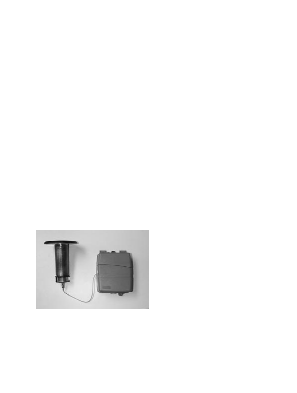
The pit version of the product has two primary components. The first is the MIU Housing
containing the electronics and battery. The MIU Housing is designed to be installed in high
humidity or flooded areas such as those located inside a meter pit or vault. The electronics in the
housing are attached by a coaxial cable to an antenna assembly. The antenna assembly is designed
to mount in the meter pit lid through a 1-3/4” hole that is drilled in the lid. The upper part of the
antenna is about 4” in diameter and slightly domed. The antenna assembly is designed to withstand
extremes in weather and traffic that it will be exposed to.
The MIU meets FCC regulations part 15.247, allowing higher output power and greater range. The
unit also meets CellNet’s “Over The Air RF Specification” which outlines the applicable
performance standards required to work within the CellNet network. The MIU uses direct
sequence spread-spectrum technology to avoid RF interference and enhance security.
A few key features of the MIU are:
• Increases meter reader safety.
• Requires no field programming.
• Improves reading efficiency
Compatible with Schlumberger ProRead equipped meters
Figure 1.1 Pit MIU

CellNet Pit MIU Master Rev. 1.0
04/14/99 3:13 PM
3
OPERATIONS OVERVIEW
The CellNet-Ready Pit MIU (ProRead Only) collects meter readings from the encoder register on
an hourly basis and transmits the information every fifteen minutes. This redundant transmission
of the same data four times an hour increases the reliability of the data to be received by the fixed
network MCC.
1-4
SPECIFICATIONS
Electrical Specifications
Transmitter Specifications
Environmental Conditions
Encoder Register Interface
Table 1.2 Electrical Specifications
Battery 3.6V D size Lithium
Transmit Period Every 15 min
Register Read Period Once an hour
Table 1.3 Transmitter Specifications
Spread Spectrum Direct Sequence
Carrier Frequency 902-928 MHz
FCC Verification Part 15.247
Table 1.4 Environmental Conditions
Operating Temperature -22° to 149°F (-30° to 65°C)
Storage Temperature -40° to 185°F (-40° to 85°C)
Operating Humidity 0 to 95% Condensing
Table 1.5 Encoder Register Interface
Encoder Register Maximum Cable Length
Schlumberger PRO-READ* 500 feet (152 meters)
* Meets manufacturers’ published specification for wire length between encoder and remote receptacle.
Dimensions and Weight
Table 1.6 Dimensions and Weight
Dimensions Refer to following figures
Weight approximately 2.2 LB (1044 grams)

CellNet Pit MIU Master Rev. 1.0
04/14/99 3:13 PM
4
SECTION 2
INSTALLATION
This section describes unpacking and storage instructions, preliminary tests, tools and materials,
site selection, and installation.
UNPACKING
As with all precision electronic instruments, the CellNet-Ready Pit MIU (ProRead Only) should be
handled with care; however, special handling is unnecessary. Inspect shipping containers for
damage upon receipt and inspect contents of any damaged cartons prior to storage. After
unpacking the MIU, inspect it for damage. If the MIU appears to be damaged, or proves to be
defective upon installation, notify your Schlumberger Sales Representative. If the MIU requires
reshipment, use the original cardboard box and packing material.
STORAGE
Store the cartons in a clean, dry environment. The temperature should remain between -40° and
185°F (-40° and 85°C). Keep in mind that the CellNet-Ready Pit MIU (ProRead Only) has an
internal battery. Storage for more than one year, of the CellNet-Ready Pit MIU (ProRead Only),
may affect product battery life. Be sure to use a first-in first-out inventory control system.
PRELIMINARY TESTS
The CellNet-Ready Pit MIU (ProRead Only) does not require any testing or programming prior to
installation.
TOOLS AND MATERIALS
Tables 2.1 and 2.2 show the recommended tools and materials you may need to successfully install
the CellNet-Ready Pit MIU (ProRead Only) or to replace the MIU’s internal battery. Note that
some items may not apply to your specific installation or the list may not contain all the required
tools and/or materials.
Table 2.1 Recommended Tools
Item Description/Recommended Use
Tool kit contains standard tools including:
• Assorted screwdrivers
• Needle-nose pliers

CellNet Pit MIU Master Rev. 1.0
04/14/99 3:13 PM
5
• Wire strippers
• Scotchlok crimping tool or Channel Locks
• Diagonal Cutters
• Electrician’s knife
• Hammer
• Various installation procedures
• Magnet with 6 lbs. force for activating the MIU
Table 2.2 Recommended Materials
Item Description/Recommendation Use
• Cable - Solid 3 conductor, #22 AWG (black/green/red) / Connecting MIU to encoder register
• Moisture protection compound Dow Corning #4 or GE Novaguard G624 ® / Covering exposed wires and
Terminal Screws on register and MIU
• Scotchloks ® / Splicing three-conductor cables and replacement battery wires
• Site Work Order Documentation provided by your utility / Receiving and recording information about the work
site
INSTALLATION
Safety and Preliminary Checks
Observe the following safety and preliminary checks before and during each installation:
• Verify that you are at the location specified on the Site Work Order.
• Verify that the site is safe for you and your equipment.
• Notify the customer of your presence and tell the customer that you might need access to the
water meter.
• If the Site Work Order does not have an MIU ID (LAN ID) number on it, write in the ID number
of the MIU you are about to install. If the Site Work Order already has a MIU ID number on it,
verify that it matches the LAN ID number on the MIU you are about to install.
Note: Always follow your company’s safety practices and installation guidelines when installing
an MIU.
• Never perform an installation during a lightning storm or under excessively wet conditions.
• Use only approved climbing equipment.
Site Selection
The CellNet-Ready Pit MIU (ProRead Only) should be installed and operated in an environment
where the temperature stays between -22° and 149°F (-30° and 65°C). Installation and operation in
moderate temperatures increases reliability and product life.

CellNet Pit MIU Master Rev. 1.0
04/14/99 3:13 PM
6
Follow these guidelines when selecting a location to install the CellNet-Ready Pit MIU (ProRead
Only):
• For best results, Schlumberger recommends mounting the MIU in a location that provides a
direct line-of-sight to the MCC.
• The selected location should be clear of all obstructions.
• Avoid installing the MIU behind metal fences or walls.
• RF line-of-sight must be verified to a nearby MCC for improved signal strength.
Table 2.3 Maximum Cable Lengths
Encoder Register Maximum Cable Length
Schlumberger PRO-READ ® * 500 feet (152 meters)
* Meets manufacturers’ published specification for wire length between encoder and remote receptacles.
Verifying/Preparing the Encoder Register
The CellNet-Ready Pit MIU (ProRead Only) is designed for use with Schlumberger ProRead
Encoder Rev. C, D and E.
Before installing an MIU, the encoder register must be correctly wired and/or programmed to work
with the MIU.
Note: The Pro-Read ® encoder must be programmed for three-wire mode using a Pro-Read ®
Programmer and it’s ten-digit TDI format. Do this through the Pro-Read ® receptacle before
removing the receptacle. For more information about Pro-Read ® programmers, contact your
Schlumberger sales representative.
A three-conductor wire is required to connect the MIU to the encoder. Refer to Steps 1 - 9 in this
procedure for that information.
If a three-conductor cable already connects a Pro-Read ® encoder register to a Pit-mounted
receptacle, verify the Pro-Read ® is programmed for three-wire mode.
If a three-conductor cable already connects a Pro-Read ® encoder register to a Pit-mounted
receptacle, the cable may have to be extended to a location that is appropriate for mounting the
MIU. Refer to the section “Splicing a Three-Conductor Cable.”
Connecting the MIU to the ProRead ® encoder:
1. Remove the terminal screw cover from the encoder register.
2. Strip off 3/4" from the jacket of the three-conductor cable.
3. Strip off 1/2" of insulation from each of the three wires.
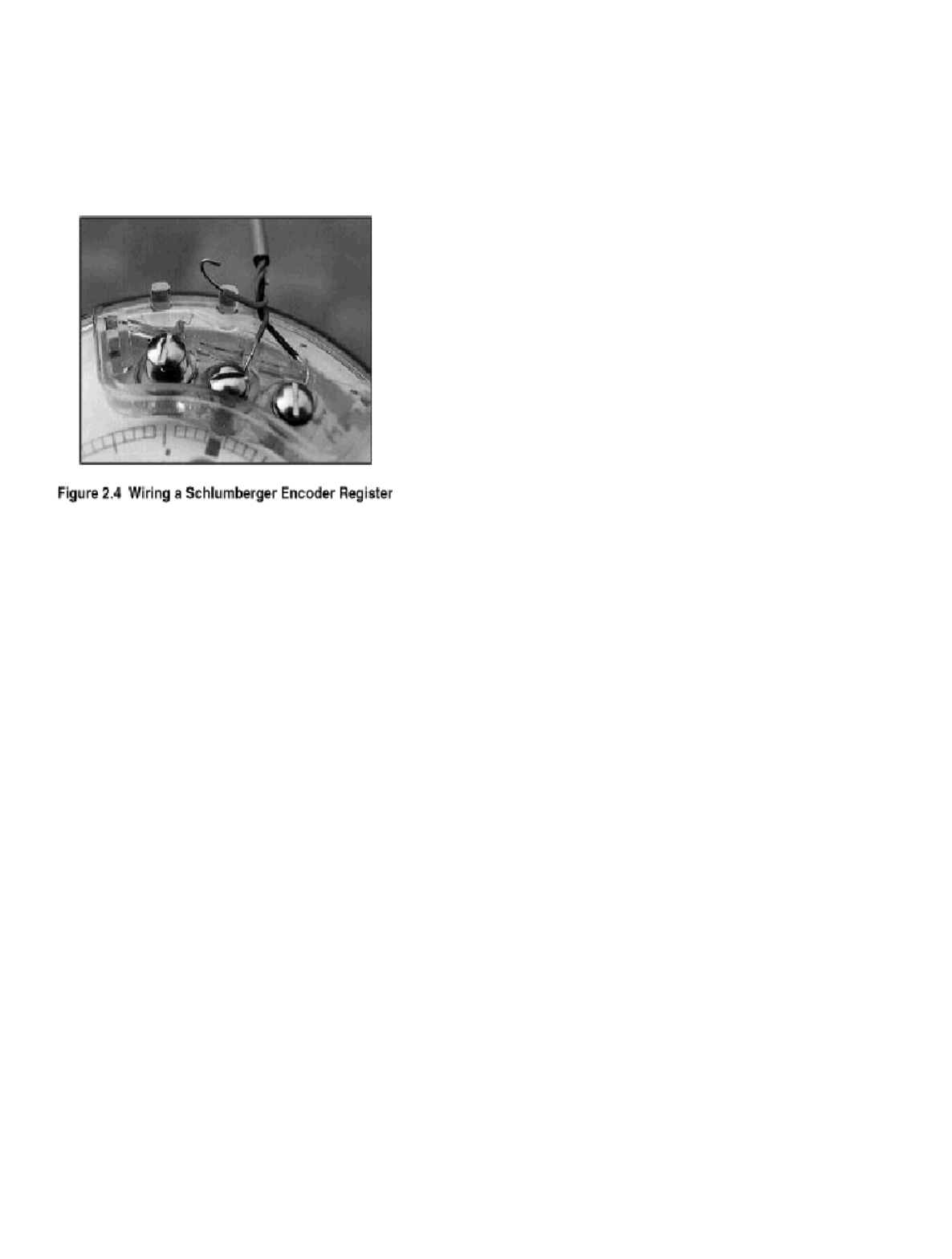
4. Connect one wire to each terminal screw as described in Table 2.4 and shown in Figure 2.4.
CellNet Pit MIU Master Rev. 1.0
04/14/99 3:13 PM
7
Table 2.4 Encoder Register Interface
Encoder Register Wire Color / Encoder Terminal
Schlumberger Pro-Read ® Black / B Green / G Red / R
CellNet Pit MIU Master Rev. 1.0
04/14/99 3:13 PM
8
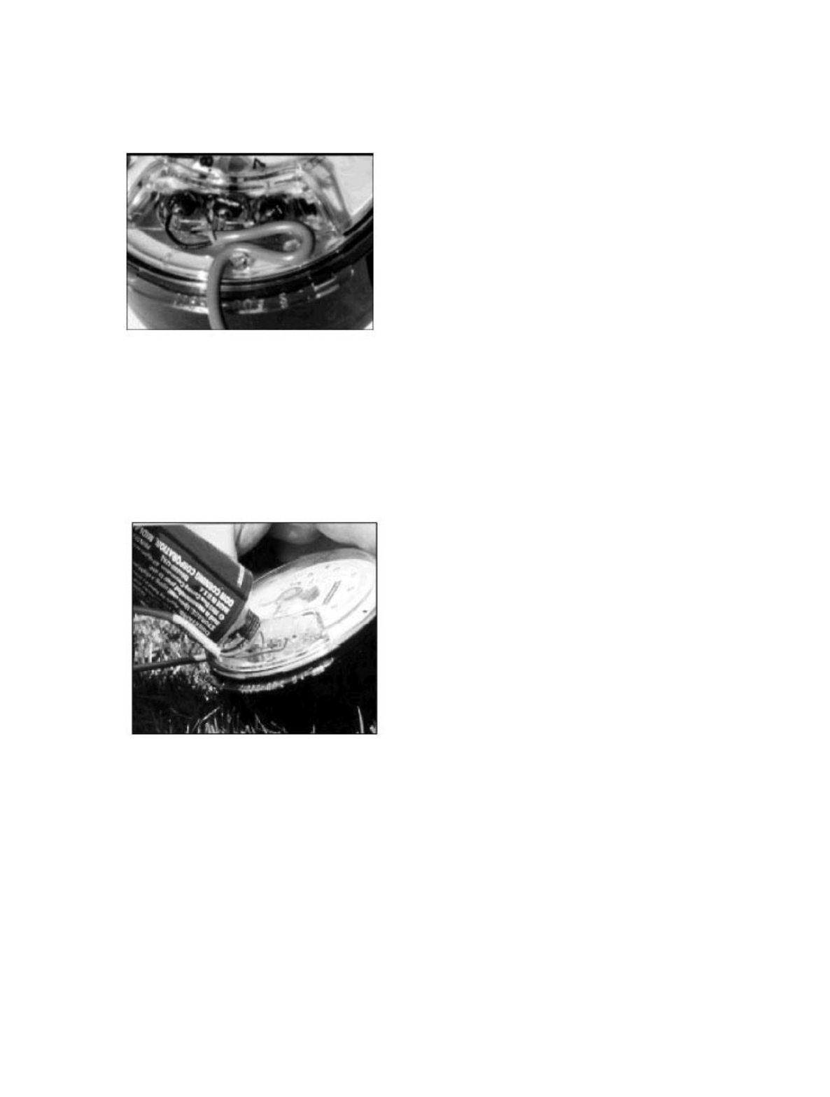
5. Thread the cable around the strain relief posts (Figure 2.5).
Figure 2.5 Cable Threaded Around Strain Relief Posts
6. Use a generous amount of moisture protection compound (Dow Corning #4 ®
or GE Novaguard G624 ® ) to completely cover the terminal screws and exposed wire (Figure 2.6).
Figure 2.6 Installing Moisture Protection Compound
CellNet Pit MIU Master Rev. 1.0
04/14/99 3:13 PM
9
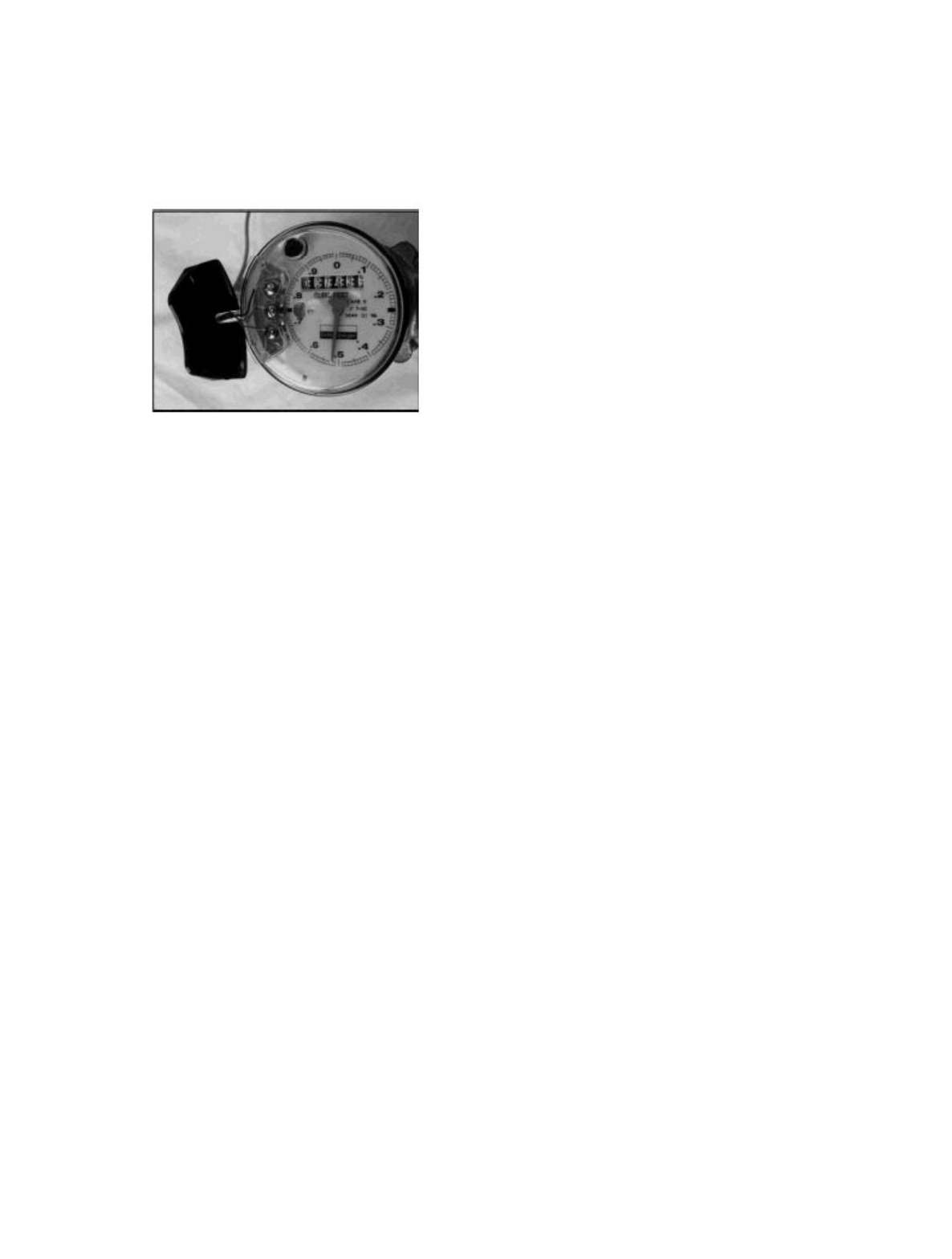
7. Align the cable with the notch in the terminal screw cover and snap the cover
onto the encoder register (Figure 2.7).
Figure 2.7 Covering the Terminal Screws
8. Run the cable from the MIU installation point to the encoder register, fastening it securely as
necessary.

CellNet Pit MIU Master Rev. 1.0
04/14/99 3:13 PM
10
Installing the MIU
Please read and comply with all of the information in “Verifying/Preparing the Encoder Register”
before continuing with this section, “Installing the MIU.” Always be sure to comply with OSHA
Safety Standards for confined space entry.
CellNet-Ready Pit MIU (ProRead Only) Installation
1. Unscrew the small tube with attached cable from the antenna assembly.
2. Remove the plastic nut from the antenna assembly.
3. Insert the antenna assembly in the 1 ¾” hole in the meter pit lid.
4. Secure the antenna assembly to the pit lid by tightening the plastic nut from the underside of
the lid.
5. Make sure the o-ring is in place in the groove on the top of the small tube with attached cable.
6. Thread the small tube with attached cable into the antenna assembly until tube bottoms out in
the antenna assembly.
Testing the Installation
Refer to Section 5, “Testing And Maintenance.”
Completing the Installation
After verifying that the MIU is working correctly, follow these steps to complete the installation:
1. Install the Hi-Lo fastener that holds the Main Housing to the Mounting Adapter.
2. Use a generous amount of moisture protection compound (Dow Corning #4 or
GE Novaguard G624) to completely cover the Terminal Screws and exposed wires.
3. Slide the Terminal Cover onto the Main Housing. Make sure the Terminal Cover is seated
properly and the cable is fitted into the notch at the top of the Terminal Cover.
4. Install the Seal Pin into the Terminal Screw Cover.
5. Install a seal wire or seal clip through the Seal Holes at the bottom of the Main Housing.
(optional)
6. Verify that the requirements of the Site Work Order have been met and that you have recorded
all required information.
7. Clean up the installation site before leaving.
CellNet Pit MIU Master Rev. 1.0
04/14/99 3:13 PM
11
Splicing A Three-Conductor Cable
Splicing three-conductor cables together should be avoided whenever possible. However, if an
existing Pro-Read ® Pit receptacle is not in an appropriate location for replacement by an MIU, it
may be necessary to splice the cable and extend it to an appropriate location.
Follow these steps to splice a three-conductor cable:
1. Remove the receptacle from the Pit.
2. Remove the wires from the receptacle.
3. Cut away the exposed copper from each wire.
4. On the three-conductor cable to be spliced, strip off at least 1" of the outer jacket. Do not strip
the insulation from the individual wires.
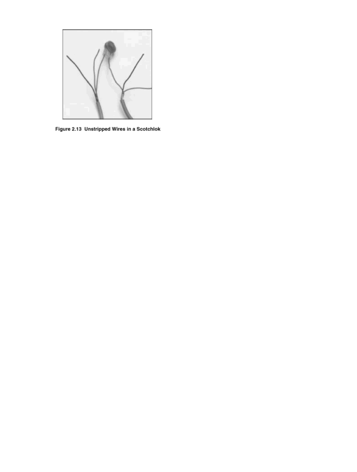
5. Match up one pair of colored wires (Black to Black, Green to Green, and Red to Red) and insert
the matching-colored pair into a Scotchlok (Figure 2.13).
Note: The Pro-Read® encoder must be programmed for three-wire mode using a Pro-Read ®
programmer and its ten-digit TDI format. Do this through the Pro-Read ® receptacle before
removing the receptacle.
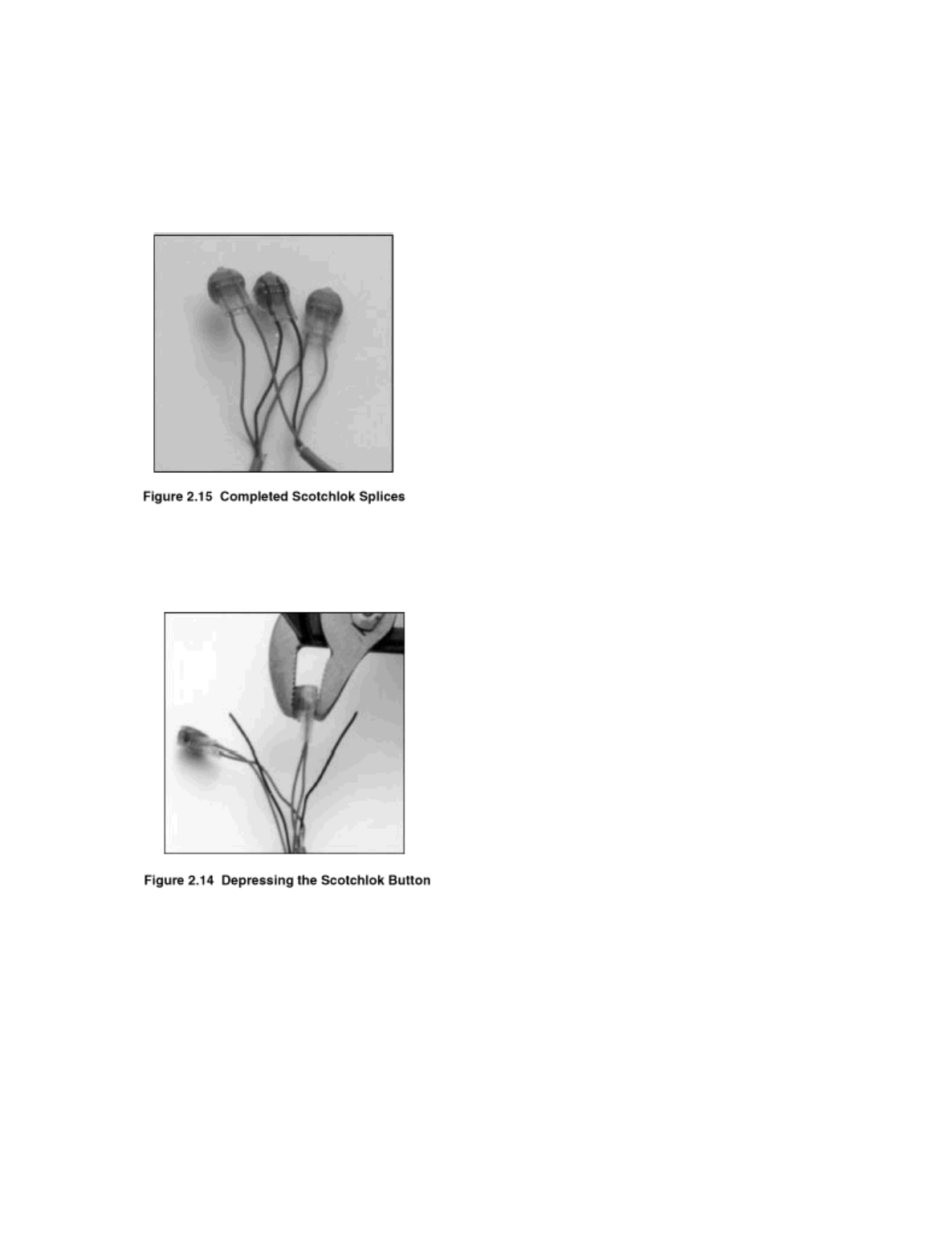
6. Using a Scotchlok crimping tool or a pair of Channel locks, squeeze the “button” on the
Scotchlok until it is completely flat (Figure 2.14).
CellNet Pit MIU Master Rev. 1.0
04/14/99 3:13 PM
12
7. Inspect the Scotchlok to verify that both wires are fully inserted. If they are not, redo the splice
(Figure 2.15).
8. Repeat Steps 5 through 7 for each pair of wires.
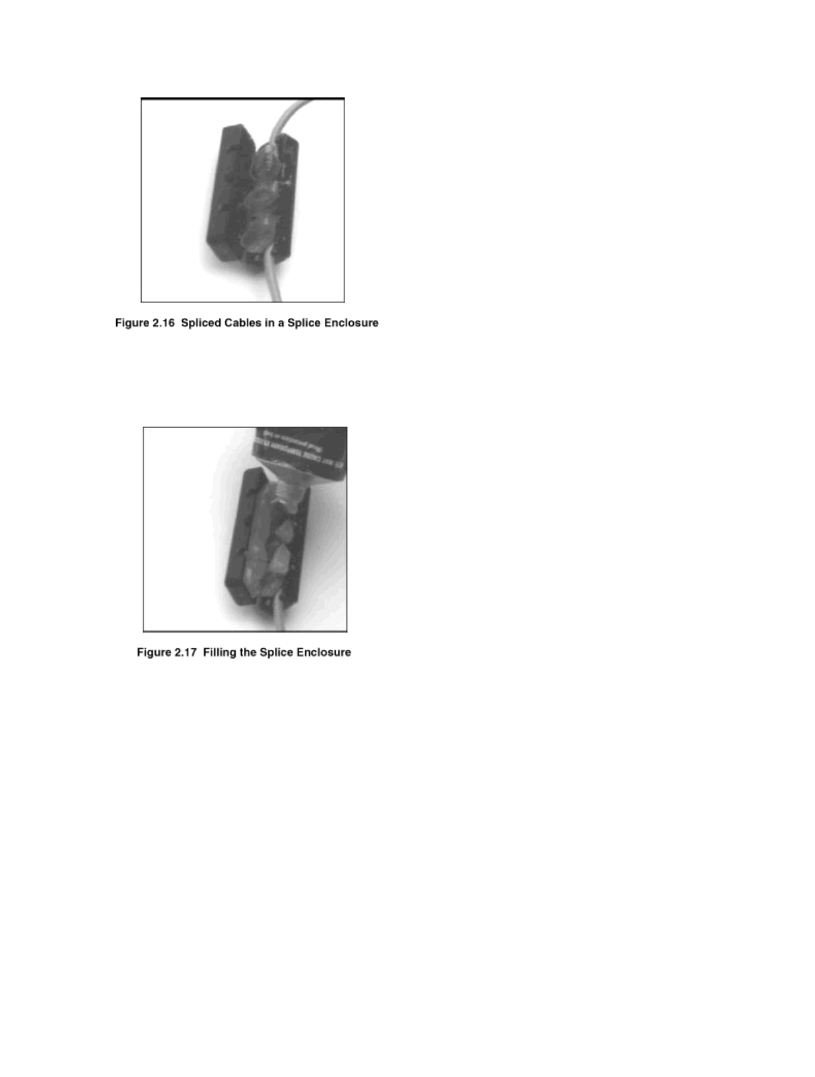
9. Tuck the Scotchloks into a splice enclosure and route the cables through the cutouts at the ends
of the splice enclosure (Figure 2.16).
CellNet Pit MIU Master Rev. 1.0
04/14/99 3:13 PM
13
10. Coat the inside of the splice enclosure with Dow Corning #4 ® or GE Novaguard G624 ®
moisture protection compound (Figure 2.17).
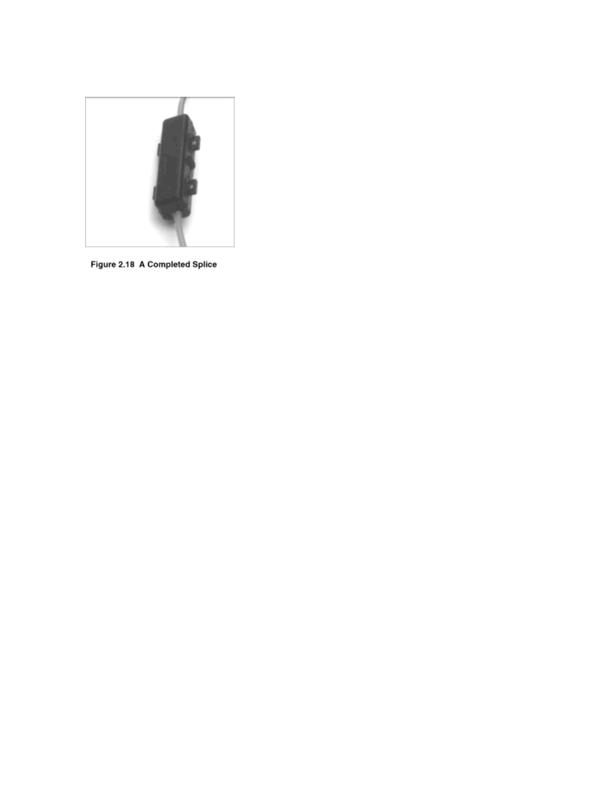
11. Close the splice enclosure, pressing it firmly until the teeth lock together
(Figure 2.18).
CellNet Pit MIU Master Rev. 1.0
04/14/99 3:13 PM
14
REPLACING THE BATTERY
Follow these steps to change-out a Pit MIU’s internal Battery:
1. Unscrew the Hi-Lo fastener holding the Main Housing to the Mounting Adapter.
2. Remove the seal wire or seal clip from the Seal Holes at the bottom of the Main Housing.
3. Punch the Seal Pin out of the Terminal Screw Cover.
4. Remove the Terminal Screw Cover.
5. Remove the wires from the Terminal Screws. (optional)
6. Using a flat-head screwdriver, gently pry open the clip on the bottom of the Main Housing.
When the clip clears the tab on the Mounting Adapter, pull the Main Housing away from the
Mounting Adapter.
7. Remove the Main Housing by lifting and unhinging it from the Mounting Adapter.
8. Remove the Battery from the Main Housing by pressing in on the right end of the Battery until it
releases and comes free from the Main Housing.
9. As close to the Battery as possible, cut the battery connection wires one at a time.
Note: Cutting the battery connection wires one at a time prevents shorting.
10.Use Skotchloks to splice the wires from the new Battery to the wires that connected to the old
Battery.
Note: Insure the Pit MIU’s black wire is connected to ground (-) and the red wire is connected to
the positive (+) wires of the new battery.

CellNet Pit MIU Master Rev. 1.0
04/14/99 3:13 PM
15
11. Snap the Battery into the Receiving Clips on the Main Housing.
12. Install the Main Housing on the Mounting Adapter.
14. Install the appropriate color wires to each Terminal Screw (Black to B, Green to G, Red to R).
15. Follow the steps in “Testing the Installation.”
SECTION 3
OPERATING INSTRUCTIONS
At the time of installation, the installer uses the CellNet installation tool to verify that the CellNet-
Ready Pit MIU (ProRead Only) is operating properly. Following the installation, the CellNet-
Ready Pit MIU (ProRead Only) operates automatically and continuously without any type of
human intervention.
SECTION 4
THEORY OF OPERATION
CellNet ® MIU Programming
The MIU is not field programmable. At the factory, each of the following items are programmed
into the MIU:
LAN Address - Each MIU is given a unique, numeric LAN address.
Time between encoder register reads -The time between encoder register reads is one hour.
Time between MIU transmissions - The time between MIU transmissions is 15 minutes on
average.
RF Protocol Error Detection
The RF protocol is comprised of a header, data packet, and an error detection mechanism that
reduces the erroneous data.
RF Transmission Period and Randomness
The random period generation uses the same CellNet ALOHA model to generate the transmit
randomness. The randomness algorithm is defined so that no two consecutive transmissions from
two MIU’s will interfere with one another.
Low Battery RF Emissions
The MIU stops RF transmissions when the battery discharges below the normal operating voltage
of 3.1 volts.

CellNet Pit MIU Master Rev. 1.0
04/14/99 3:13 PM
16
TROUBLESHOOTING
Six-Wheel Encoder Normal Operation
If the odometer reads 123456, the display should be 1 2 3 4 5 5.
Note that the last digit displayed is a five if the last digit on the odometer is five through nine. The
last digit displayed is a zero if the last digit on the odometer is zero through four.
Four-Wheel Encoder Normal Operation
If the odometer reads 123456, the display should be 1 2 3 4 0 0.
Abnormal Operation
Below are examples of abnormal operation for four-wheel encoders. Abnormal operation for six-
wheel encoders is similar except that digits occupy all six positions.
If an (H) or a ( - ) occurs on any of the four positions, the CellNet-Ready Pit MIU (ProRead Only)
will transmit the data as follows:
Examples: 1 2 E 4 0 0 or 1 2 b 4 0 0
If the wire between the CellNet-Ready Pit MIU (ProRead Only) and the encoder is cut or reads as
open, or if the encoder is not programmed in a three-wire TDI format, the MIU will transmit the
following data:
Example: AAAAAA
SECTION 5
TESTING AND MAINTENANCE
After the CellNet-Ready Pit MIU (ProRead Only) has been installed and wired, follow these steps
to verify that the MIU is working properly:
1. Activate the MIU by holding the magnet for two seconds against the arrow on the Main
housing. The arrow is just to the right of the Terminal Screws.
2. Use a CellNet installation tool to verify the transmission from the Pit MIU.
3. Verify all electrical connections.
4. Test the installation again.
5. If a Pro-Read ® Encoder Register is used, ensure the unit is programmed in the 3-wire, ten digit
TDI format.
6. Verify all electrical connections.
7. Reactivate the MIU. (See Step 1)
8. If a problem still exists, install a different MIU.

CellNet Pit MIU Master Rev. 1.0
04/14/99 3:13 PM
17
FCC REGULATORY NOTICE
Service Return Address:
Schlumberger RMS, Inc.
1600 Alabama HWY 229 S.
Tallassee, AL 36078
This CellNet-Ready Pit MIU (ProRead Only) has been tested and found to comply with the limits for a
Class B digital device, pursuant to Part 15 of the FCC Rules. These limits are designed to provide
reasonable protection against harmful interference in a residential installation. This equipment generates,
uses and can radiate radio frequency energy and, if not installed and used in accordance with the
instructions, may cause harmful interference to radio communications. However, there is no guarantee
that interference will not occur in a particular installation. If this equipment does cause harmful
interference to radio or television reception, which can be determined by turning the equipment off and
on, the user is encouraged to try to correct the interference by one or more of the following measures:
-- Reorient or relocate the receiving antenna.
-- Increase the separation between the equipment and receiver.
-- Connect the equipment into an outlet on a circuit different from that to which the receiver is connected.
-- Consult the dealer or an experienced radio/TV technician for help.
(c) The provisions of paragraphs (a) and (b) of this section do not apply to digital devices exempted
from the technical standards under the provisions of §15.103.
(d) For systems incorporating several digital devices, the statement shown in paragraph (a) or (b) of
this section needs to be contained only in the instruction manual for the main control unit.
Caution, changes or modifications not expressly approved by the party responsible for compliance could
void the user's authority to operate the equipment.