Neptune Technology Group NTGSRFV3 WIRELESS LAN RADIO User Manual 04 0044 Manual
Neptune Technology Group Inc. WIRELESS LAN RADIO 04 0044 Manual
USERS MANUAL

Model: R900-v3 Advanced Compliance Solutions FCC ID: P2SNTGSRFV3
Frequency Hopping
Spread Spectrum Transmitter
Certification Test Report
Model: R900-V3
FCC ID: P2SNTGSRFV3
ACS Report Number: 04-0044-15C
Manual

Model: R900-v3 Advanced Compliance Solutions FCC ID: P2SNTGSRFV3
Information to User
FCC Notice
“NOTE: This equipment has been tested and found to comply with the limits for a Class B digital de4vice,
pursuant to Part 15 of the FCC Rules. These limits are designed to provide reasonable protection against
harmful interference in a residential installation. This equipment generates, uses and can radiate radio
frequency energy and, if not installed and used in accordance with the instructions, may cause harmful
interference to radio communications. However, there is no guarantee that interference will not occur in a
particular installation. If the equipment does cause harmful interference to radio or television reception,
which can be determined by turning the equipment off and on, the user is encouraged to try to correct the
interference by one or more of the following measures:
• Reorient or relocate the receiving antenna.
• Increase the separation between the equipment and receiver.
• Connect the equipment to an outlet on a circuit different from that to which the receiver is connected.
• Consult the dealer or an experienced radio/TV technician for help.”
RF Exposure Information
This equipment complies with the FCC RF radiation requirements for uncontrolled environments. To
maintain compliance with these requirements, the antenna and any radiating elements would be installed
to ensure that a minimum separation distance of 20 cm is maintained from the general population.
Industry Canada Notice
This Class B digital apparatus meets all requirements of the Canadian Interference Causing Equipment
Regulations. Operation is subject to the following two conditions: (1) this device may not cause harmful
interference, and (2) this device must accept any interference received, including interference that may
cause undesired operation.
Cet appareillage numérique de la classe B répond à toutes les exigences de l'interférence canadienne
causant des règlements d'équipement. L'opération est sujette aux deux conditions suivantes: (1) ce
dispositif peut ne pas causer l'interférence nocive, et (2) ce dispositif doit accepter n'importe quelle
interférence reçue, y compris l'interférence qui peut causer l'opération peu désirée.
Model: R900-v3 Advanced Compliance Solutions FCC ID: P2SNTGSRFV3
Installation guide
The R900V3 MIU is designed for use with four types of encoder registers: Neptune ARB V, ProRead,
Sensus ECRII & Invensys ECRIII. Before installing an MIU, the encoder registers must be correctly wired
and/or programmed to work with the MIU.
Note: When a ProRead encoder register is used, the ProRead register must be programmed for
three-wire mode.
If the MIU will be connected to a new ProRead encoder register, or if a three-conductor cable is already
connected to a ProRead encoder register, ensure that the ProRead register is programmed for three-wire
mode using the ProRead programmer and its RF/MIU 6, 8, or 10 ID TDI format. This can be
accomplished through the ProRead receptacle before removing the receptacle.
Wiring the encoder register
Run a three-conductor cable from the encoder register to the MIU.
Refer to the steps below.
Connect the 3-conductor wire to the encoder register’s terminals per the manufacturer’s instructions,
using the color code
in Table 1.
1. Thread the cable around the strain relief posts of the encoder.
2. Apply moisture protection compound to the terminal screws and exposed wires. (Neptune
recommends Dow Corning Compound #4).
3. Snap the cover onto the encoder register.
4. Proceed to the section entitled “Installing the MIU.”
Table 1
Encoder Register
Wire Color / Encoder Terminal
Neptune ARB V Black / B Green / G Red / R
Neptune ProRead Black / B Green / G Red / R
Neptune E-Coder Black / B Green / G Red / R
Sensus ECRII Black / R Green / B Red / G
Testing the MIU Installation
After the MIU has been installed and wired, follow these steps to verify that the MIU is working properly:
Power up the handheld unit (HHU) test device and start the testing
program provided.

Model: R900-v3 Advanced Compliance Solutions FCC ID: P2SNTGSRFV3
Warning:
To avoid RF signal saturation of the HHU, position the receiver at least 2 to 3 feet from
the MIU.
When the MIU is installed correctly, its MIU ID and a meter-reading will appear on the HHU’s display
within one minute. Verify that this is the correct meter reading by comparing it to the meter’s dial.
If a meter-reading does not appear on the HHU’s display or the meter reading in the HHU’s display is not
the same as the reading on the meter’s dial:
Reactivate the MIU using the magnet.
Verify all electrical connections.
Test the installation again (repeat above steps).
If a ProRead Encoder Register is used:
Insure the unit is programmed in “3-wire mode”.
Verify all electrical connections.
Reactivate the MIU using the magnet
If a problem still exists contact your Neptune representative.
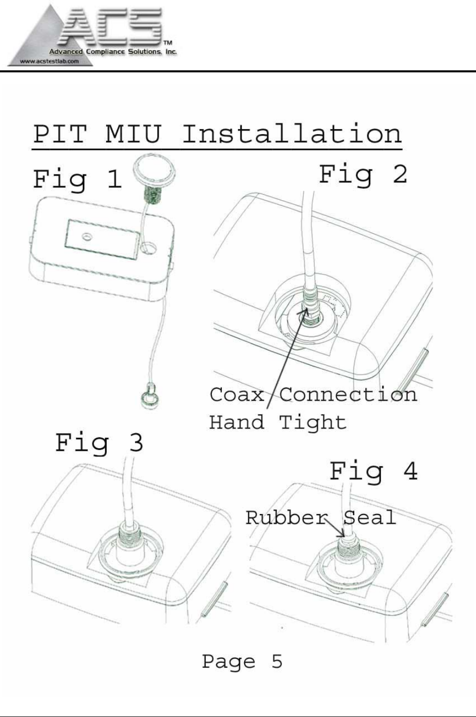
PIT MIU Installation
Note: Before wiring the encoder register, make sure the cable is long enough so that
when the installation is complete, the pit lid (with MIU attached) can be removed easily
without straining the cable.
1. Feed the antenna cable and housing through the 1 ¾” hole in the meter pit lid. Slip the large plastic
nut over the antenna cable and thread it onto the antenna assembly to secure it to the pit lid (Figure
1).
2. Connect the coaxial cable connector to the connector on the transmitter housing (Figure 2).
3. Making sure the washer is properly seated, connect the plastic connector housing to the 3-lobed
black plastic latch-plate
(Figure 3).
4. Slide the black conical-shaped gasket down the cable until it engages the connector housing (Figure
4).
5. Tighten the connector nut onto the threaded portion of the connector housing (Figure 5).
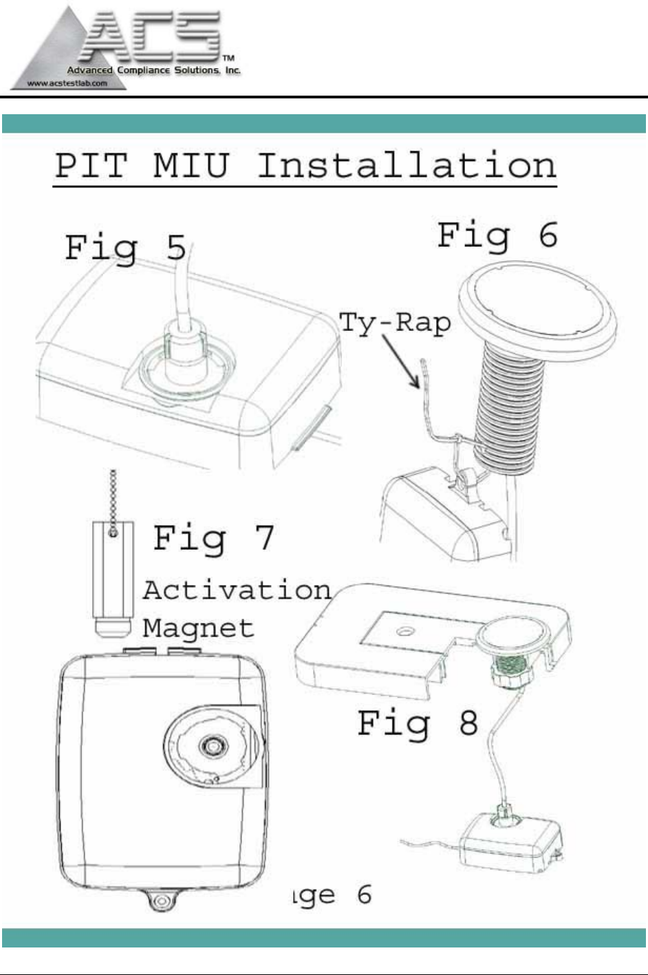
6. If desired, use the included cable tie to hang the MIU from the antenna tube (Figure 6).
7. Place the magnet against the side of the MIU in the area shown and swipe it in the indicated direction
to activate the MIU
(Figure 7).
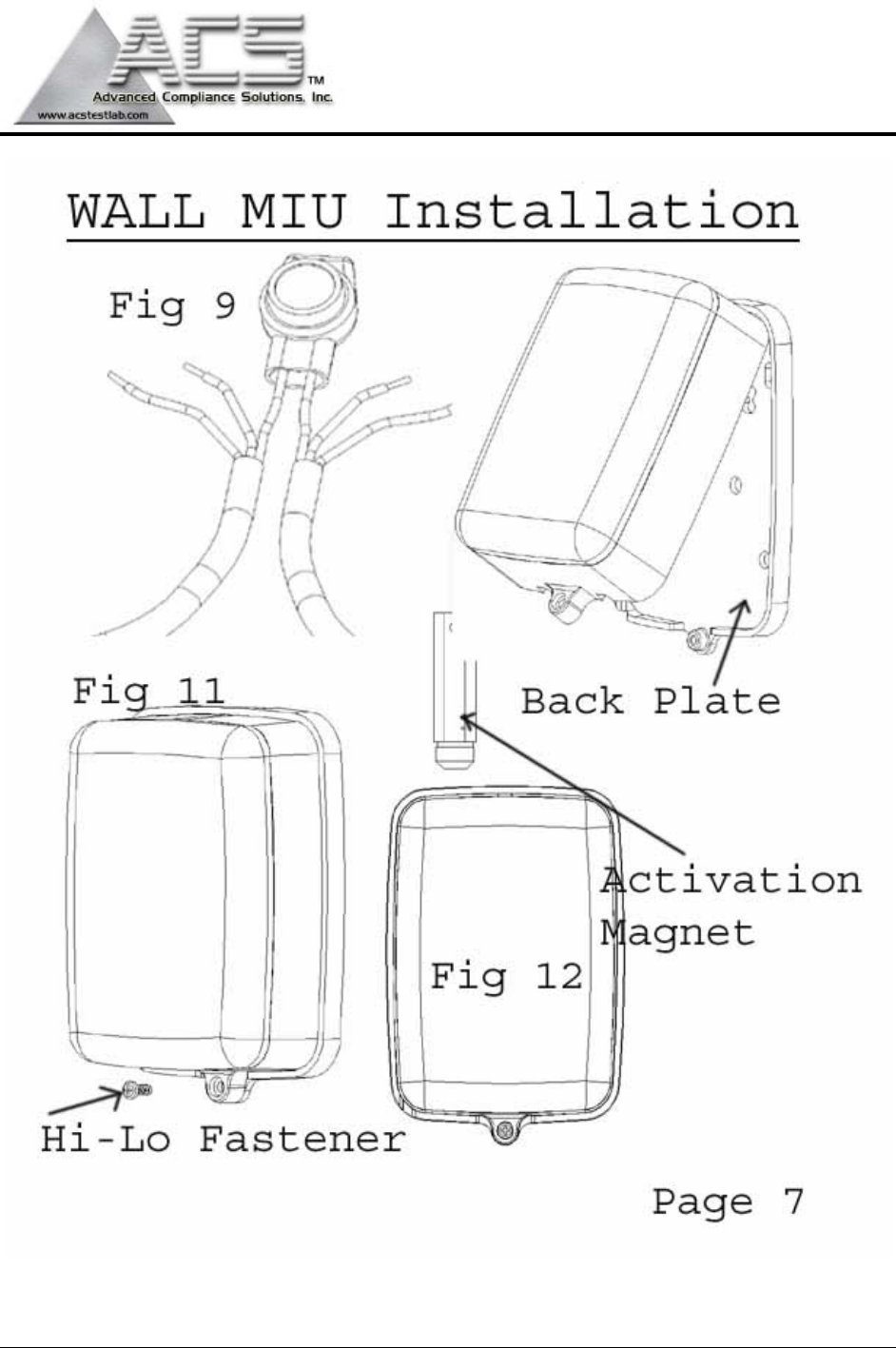
Wall MIU Installation
Gel caps should be used to connect the pigtail from the MIU to the register wire.
When using the Scotchlok gel caps, pair the wires according to the color chart in Table 1. With the
ends of the colored wires stripped approximately ¼”, slide the pair into the gel cap as far as they will go.
Then, firmly squeeze the gel cap with an appropriate crimping tool. One gel cap should be used for each
colored wire pair.

Model: R900-v3 Advanced Compliance Solutions FCC ID: P2SNTGSRFV3
(See picture 9.)
Proceed to the section entitled “Installing the MIU.”
Installing the Wall MIU
1. Attach the mounting adapter to the wall using the appropriate holes.
2. Storing the excess wire in the hollow cavity on the back of the MIU, slide the tongue on the top of the
MIU into the groove on the top of the mounting adapter (Figure 10).
3. Secure the MIU to the mounting adapter using the Hi/Lo fastener provided (Figure 11).
4. Place the magnet against the side of the MIU in the area shown and swipe it in the indicated direction
to activate the MIU
(Figure 12).
Note: For best performance in Fixed-Network configuration, wall MIU may be
mounted horizontally.
Model: R900-v3 Advanced Compliance Solutions FCC ID: P2SNTGSRFV3

Model: R900-v3 Advanced Compliance Solutions FCC ID: P2SNTGSRFV3
Model: R900-v3 Advanced Compliance Solutions FCC ID: P2SNTGSRFV3

Model: R900-v3 Advanced Compliance Solutions FCC ID: P2SNTGSRFV3
Model: R900-v3 Advanced Compliance Solutions FCC ID: P2SNTGSRFV3