Neptune Technology Group R450 METER READING TRANSMITTER User Manual R901 installation guide
Neptune Technology Group Inc. METER READING TRANSMITTER R901 installation guide
USERS MANUAL
ARB UTILITY MANAGEMENT SYSTEMS WATER |ELECTRIC |GAS
E-Cod
R450 WALL AND PIT USER'S MANUAL
R450 Wall and Pit User's Manual


R450 Wall and Pit User’s Manual
ARB UTILITY MANAGEMENT SYSTEMS WATER | ELECTRIC | GAS

This manual is an unpublished work and contains the trade secrets and confidential information of Neptune Technology
Group Inc., which are not to be divulged to third parties and may not be reproduced or transmitted in whole or part, in
any form or by any means, electronic or mechanical for any purpose, without the express written permission of Nep-
tune Technology Group Inc. All rights to designs or inventions disclosed herein, including the right to manufacture, are
reserved to Neptune Technology Group Inc.
The information contained in this document is subject to change without notice. Neptune reserves the right to change
the product specifications at any time without incurring any obligations.
Trademarks used in this manual
R450 is a trademark of Neptune Technology Group Inc. Other brands or product names are the trademarks or registered
trademarks of their respective holders.
FCC Notice
This device complies with part 15 of the FCC Rules. Operation is subject to the condition that this device does not
cause harmful interference.
NOTE: This equipment has been tested and found to comply with the limits for a Class B digital device, pursuant to
Part 15 of the FCC Rules. These limits are designed to provide reasonable protection against harmful interference in a
residential installation. This equipment generates, uses, and can radiate radio frequency energy and, if not installed
and used in accordance with the instructions, may cause harmful interference to radio communications. However, there
is no guarantee that interference will not occur in a particular installation. If this equipment does cause harmful inter-
ference to radio or television reception, which can be determined by turning the equipment off and on, the user is
encouraged to try to correct the interference by one or more of the following measures:
• Reorient or relocate the receiving antenna.
• Increase the separation between the equipment and receiver.
• Connect the equipment into an outlet on a circuit different from that to which the receiver is connected.
• Consult the dealer or an experienced radio/TV technician for help.
RF Exposure Information
This equipment complies with the FCC RF radiation requirements for uncontrolled environments. To maintain compli-
ance with these requirements, the antenna and any radiating elements should be installed to ensure that a minimum
separation distance of 20cm is maintained from the general population.
Professional Installation
In accordance with section 15.203 of the FCC rules and regulations, the MIU must be professionally installed by trained
utility meter installers.
Changes or modifications not expressly approved by the party responsible for compliance could void
the user's authority to operate the equipment.
Industry Canada
This Class B digital apparatus meets all requirements of the Canadian Interference Causing Equipment Regulations.
Operation is subject to the following two conditions: (1) this device may not cause harmful interference, and (2) this
device must accept any interference received, including interference that may cause undesired operation.
Cet appareillage numérique de la classe B répond à toutes les exigences de l'interférence canadienne causant des
règlements d'équipement. L'opération est sujette aux deux conditions suivantes: (1) ce dispositif peut ne pas causer
l'interférence nocive, et (2) ce dispositif doit accepter n'importe quelle interférence reçue, y compris l'interférence qui
peut causer l'opération peu désirée.
Copyright © 2006
Neptune Technology Group Inc.
All Rights Reserved.
R450 Wall and Pit MIU User’s Manual
Literature No. UM R450 09.06
Part No. XXXXX-XXX
Neptune Technology Group Inc.
1600 Alabama Highway 229
Tallassee, AL 36078
Tel: (334) 283-6555
Fax: (334) 263-7299


Contents
R450 Wall and Pit User’s Manual v
1Product Description
Product Description . . . . . . . . . . . . . . . . . . . . . . . . . . . . . . . . . . . . . . . . . . . . . . . . . . . . . . . . . . . . . . . . . . . . . 1
R450 MIU Programming . . . . . . . . . . . . . . . . . . . . . . . . . . . . . . . . . . . . . . . . . . . . . . . . . . . . . . . . . . . . . . 1
RF Protocol Error Detection . . . . . . . . . . . . . . . . . . . . . . . . . . . . . . . . . . . . . . . . . . . . . . . . . . . . . . . . . . 1
Low Battery RF Emissions . . . . . . . . . . . . . . . . . . . . . . . . . . . . . . . . . . . . . . . . . . . . . . . . . . . . . . . . . . . . 1
2Specifications
Electrical Specifications . . . . . . . . . . . . . . . . . . . . . . . . . . . . . . . . . . . . . . . . . . . . . . . . . . . . . . . . . . . . . . . . . 2
Encoder Register Interface . . . . . . . . . . . . . . . . . . . . . . . . . . . . . . . . . . . . . . . . . . . . . . . . . . . . . . . . . . 2
Specifications - R450 Pit MIU . . . . . . . . . . . . . . . . . . . . . . . . . . . . . . . . . . . . . . . . . . . . . . . . . . . . . . . . . . . . 3
Environmental Conditions . . . . . . . . . . . . . . . . . . . . . . . . . . . . . . . . . . . . . . . . . . . . . . . . . . . . . . . . . . . . 3
Functional Specifications . . . . . . . . . . . . . . . . . . . . . . . . . . . . . . . . . . . . . . . . . . . . . . . . . . . . . . . . . . . . 3
Dimensions and Weight . . . . . . . . . . . . . . . . . . . . . . . . . . . . . . . . . . . . . . . . . . . . . . . . . . . . . . . . . . . . . 3
Specifications - R450 Wall MIU . . . . . . . . . . . . . . . . . . . . . . . . . . . . . . . . . . . . . . . . . . . . . . . . . . . . . . . . . . . 4
Environmental Conditions . . . . . . . . . . . . . . . . . . . . . . . . . . . . . . . . . . . . . . . . . . . . . . . . . . . . . . . . . . . . 4
Functional Specifications . . . . . . . . . . . . . . . . . . . . . . . . . . . . . . . . . . . . . . . . . . . . . . . . . . . . . . . . . . . . 4
Dimensions and Weight . . . . . . . . . . . . . . . . . . . . . . . . . . . . . . . . . . . . . . . . . . . . . . . . . . . . . . . . . . . . . 4
3General Installation Guidelines
Tools and Materials . . . . . . . . . . . . . . . . . . . . . . . . . . . . . . . . . . . . . . . . . . . . . . . . . . . . . . . . . . . . . . . . . 5
Safety and Preliminary Checks . . . . . . . . . . . . . . . . . . . . . . . . . . . . . . . . . . . . . . . . . . . . . . . . . . . . . . . 6
Verifying/Preparing the Encoder Register . . . . . . . . . . . . . . . . . . . . . . . . . . . . . . . . . . . . . . . . . . . . . . 6
Installation of at Register (Non Pre-Wired or Potted Only ) . . . . . . . . . . . . . . . . . . . . . . . . . . . . . . . 7
4Replacing the MIU Battery (Wall and Pit)
Removing the Battery . . . . . . . . . . . . . . . . . . . . . . . . . . . . . . . . . . . . . . . . . . . . . . . . . . . . . . . . . . . . . . 10
Cutting and Splicing the Battery Wires . . . . . . . . . . . . . . . . . . . . . . . . . . . . . . . . . . . . . . . . . . . . . . . 11
Replacing the Transmitter Cover . . . . . . . . . . . . . . . . . . . . . . . . . . . . . . . . . . . . . . . . . . . . . . . . . . . . . 12
Replacement Parts . . . . . . . . . . . . . . . . . . . . . . . . . . . . . . . . . . . . . . . . . . . . . . . . . . . . . . . . . . . . . . . . . . . . 13

Contents
vi R450 Wall and Pit User’s Manual
Glossary
Index

R450 Wall and Pit User’s Manual v
Figures
Figure Title Page
1Wall MIU . . . . . . . . . . . . . . . . . . . . . . . . . . . . . . . . . . . . . . . . . . . . . . . . . . . . . . . . . . . . . . . . . . . . . . . . . . . . . . . . . . . . . . . 1
2Pit MIU . . . . . . . . . . . . . . . . . . . . . . . . . . . . . . . . . . . . . . . . . . . . . . . . . . . . . . . . . . . . . . . . . . . . . . . . . . . . . . . . . . . . . . . . . 1
3 Pit MIU Dimensions. . . . . . . . . . . . . . . . . . . . . . . . . . . . . . . . . . . . . . . . . . . . . . . . . . . . . . . . . . . . . . . 3
4 Wall MIU Dimensions. . . . . . . . . . . . . . . . . . . . . . . . . . . . . . . . . . . . . . . . . . . . . . . . . . . . . . . . . . . . . 4
5 Wiring a Neptune Encoder Register . . . . . . . . . . . . . . . . . . . . . . . . . . . . . . . . . . . . . . . . . . . . . . . . . . 7
6 Cable Threaded Around Strain Relief Posts . . . . . . . . . . . . . . . . . . . . . . . . . . . . . . . . . . . . . . . . . . . . 8
7 Application of the Sealant . . . . . . . . . . . . . . . . . . . . . . . . . . . . . . . . . . . . . . . . . . . . . . . . . . . . . . . . . 8
8 Covering the Terminal Screws . . . . . . . . . . . . . . . . . . . . . . . . . . . . . . . . . . . . . . . . . . . . . . . . . . . . . . 9
9 Removing the MIU Transmitter Cover. . . . . . . . . . . . . . . . . . . . . . . . . . . . . . . . . . . . . . . . . . . . . . . . 10
10 The Battery Compartment. . . . . . . . . . . . . . . . . . . . . . . . . . . . . . . . . . . . . . . . . . . . . . . . . . . . . . . . . 10
11 Cutting the Battery Connection. . . . . . . . . . . . . . . . . . . . . . . . . . . . . . . . . . . . . . . . . . . . . . . . . . . . . 11
12 Splicing the New Battery . . . . . . . . . . . . . . . . . . . . . . . . . . . . . . . . . . . . . . . . . . . . . . . . . . . . . . . . . 11
13 Location of Toroid . . . . . . . . . . . . . . . . . . . . . . . . . . . . . . . . . . . . . . . . . . . . . . . . . . . . . . . . . . . . . . . 11
14 Returning Spliced Battery to Main Housing . . . . . . . . . . . . . . . . . . . . . . . . . . . . . . . . . . . . . . . . . . . 12

vi R450 Wall and Pit User’s ManualN
Notes:
Figures

R450 Wall and Pit IUser’s Manual vii
Tables
Table Title Page
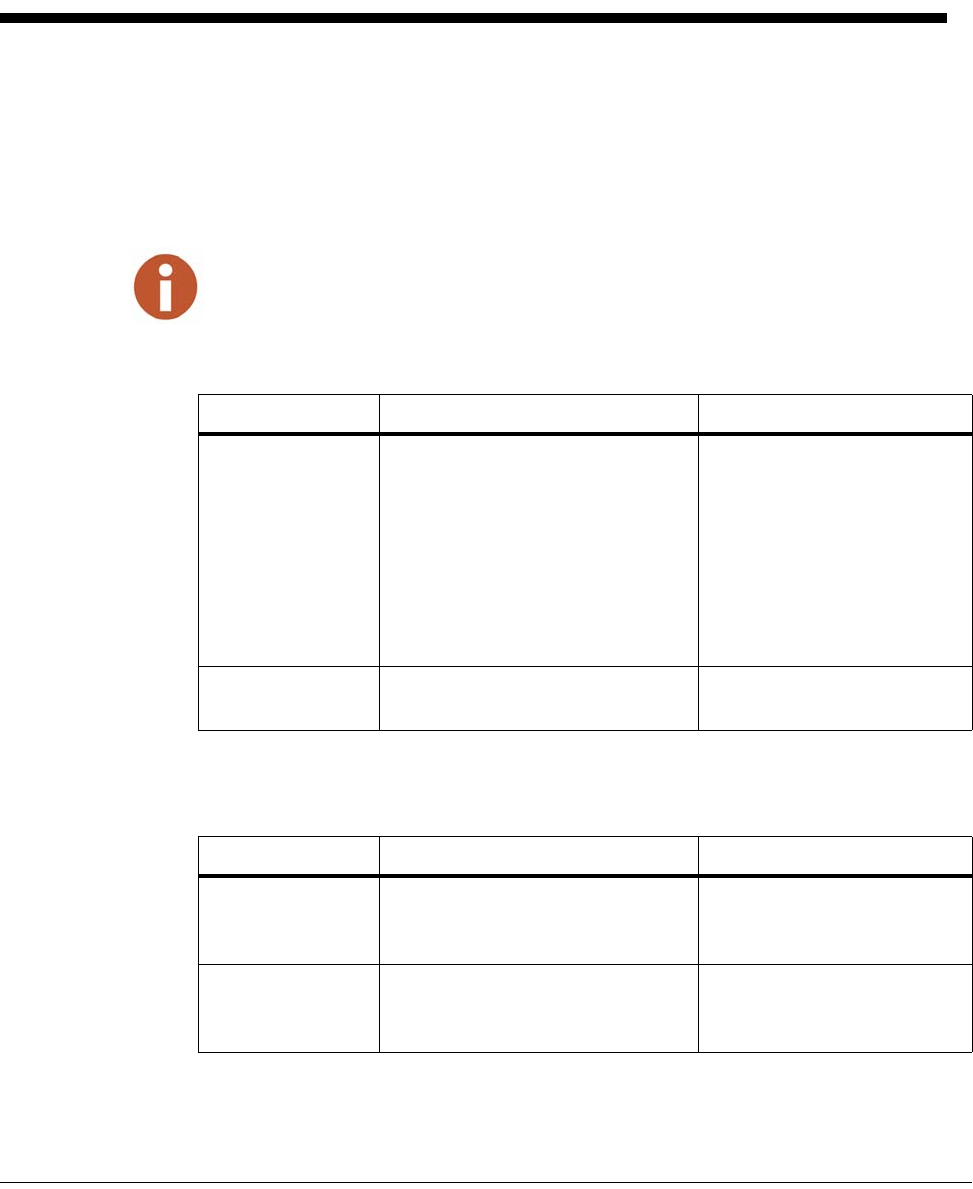
1 Recommended Tools . . . . . . . . . . . . . . . . . . . . . . . . . . . . . . . . . . . . . . . . . . . . . . . . . . . . . . . . . . . . . . . . . . . . . 5
2 Recommended Materials . . . . . . . . . . . . . . . . . . . . . . . . . . . . . . . . . . . . . . . . . . . . . . . . . . . . . . . . . . . . . . . . . 5
3 MIU Color Code for Wires . . . . . . . . . . . . . . . . . . . . . . . . . . . . . . . . . . . . . . . . . . . . . . . . . . . . . . . . . . . . . . . . 7
4 Available Replacement Parts . . . . . . . . . . . . . . . . . . . . . . . . . . . . . . . . . . . . . . . . . . . . . . . . . . . . . . . . . . . . 13

viii R450 Wall and Pit IUser’s Manual
Notes:
Tables
R450 Wall and Pit MIU User’s Manual 1
1 Product Description
This section provides a general description of the R450 Meter Interface Unit (sub-
sequently referred to as R450 MIU or MIU).
The R450 MIU by Neptune is a compact electronic device that collects meter read-
ing data from an encoder register. It then transmits the data for collection.
The R450 MIU is easily installed and requires an Federal Communications
Commission (FCC) license to operate.
Product Description
R450 MIU Programming
The MIU is NOT field programmable. At the factory, each of the following items are
programmed into the MIU:
Serial numbers – Each MIU is given two unique serial numbers/identification num-
bers (two IDs for compound units). Even numbers are given to the single registers
and odd numbers are given to a two-networked registers unit. Custom serial num-
bers are not available.
RF Protocol Error Detection
The RF protocol is comprised of a header, data packet, and an error detection
mechanism that reduces the erroneous data.
Low Battery RF Emissions
The MIU stops RF transmissions when the battery discharges below the normal
operating voltage.
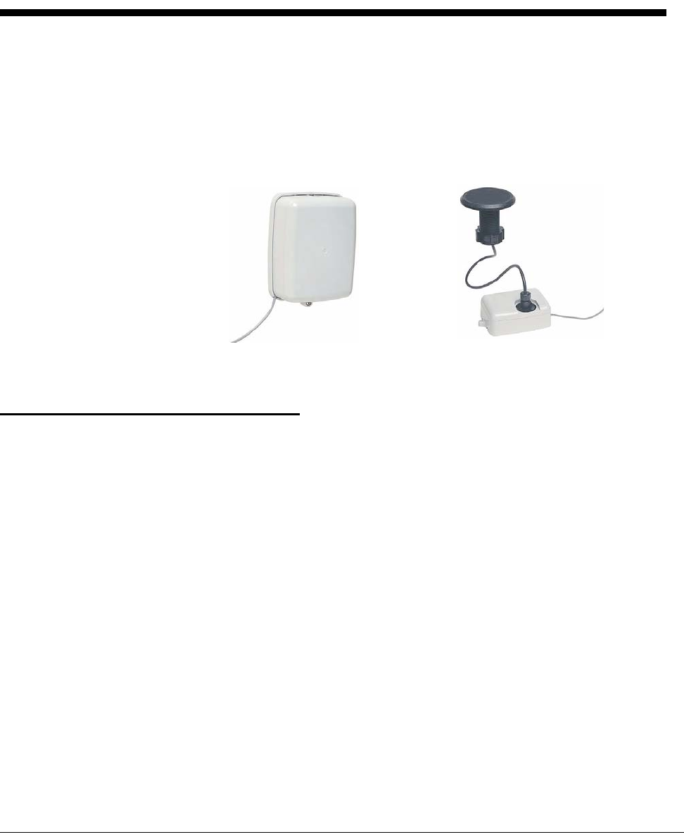
Figure 1 Wall MIU Figure 2 Pit MIU

R450 Wall and Pit MIU User’s Manual 2
2 Specifications
This section provides you with the specifications for the R450 MIU.
Electrical Specifications
Encoder Register Interface
Supported Encoder Maximum Cable Length
Neptune ARB® V2300 feet (91 meters)
Neptune ProRead (ARB® VI)
and E-Coder (ARB® VII)
500 feet (152 meters)
Invensys ECR II®and ECR III®3 200 feet (61 meters)
Networked Neptune ProRead (ARB VI) /
E-Coder (ARB VII)
250 feet (76 meters)
2The length, which meets manufacturers’ published specification for wire length between encoder and remote receptacle,
is based on solid 3 conductor wire, 22 AWG.
3Only specific formats of ECRIII programming are compatible. Contact Neptune for details.
Specifications
R450 Wall and Pit MIU User’s Manual 3
Specifications - R450 Pit MIU
Environmental Conditions
Functional Specifications
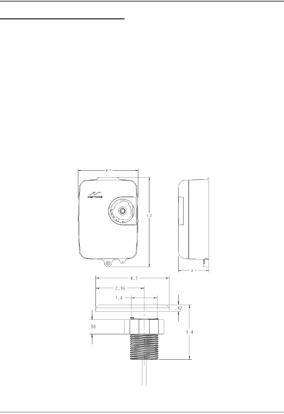
Dimensions and Weight
Figure 3 Pit MIU Dimensions
Operating Temperature -22° to 149°F (-30° to 65°C)
Storage Temperature -40° to 158°F (-40° to 70°C)
Operating Humidity 0 to 95% Condensing
Register Reading 8 digits
MIU ID 9 digits
Dimensions Refer to Figure 3
Weight 1.0 lbs. (454 grams)
Specifications
4R450 Wall and Pit MIU User’s Manual
Specifications - R450 Wall MIU
Environmental Conditions
Functional Specifications
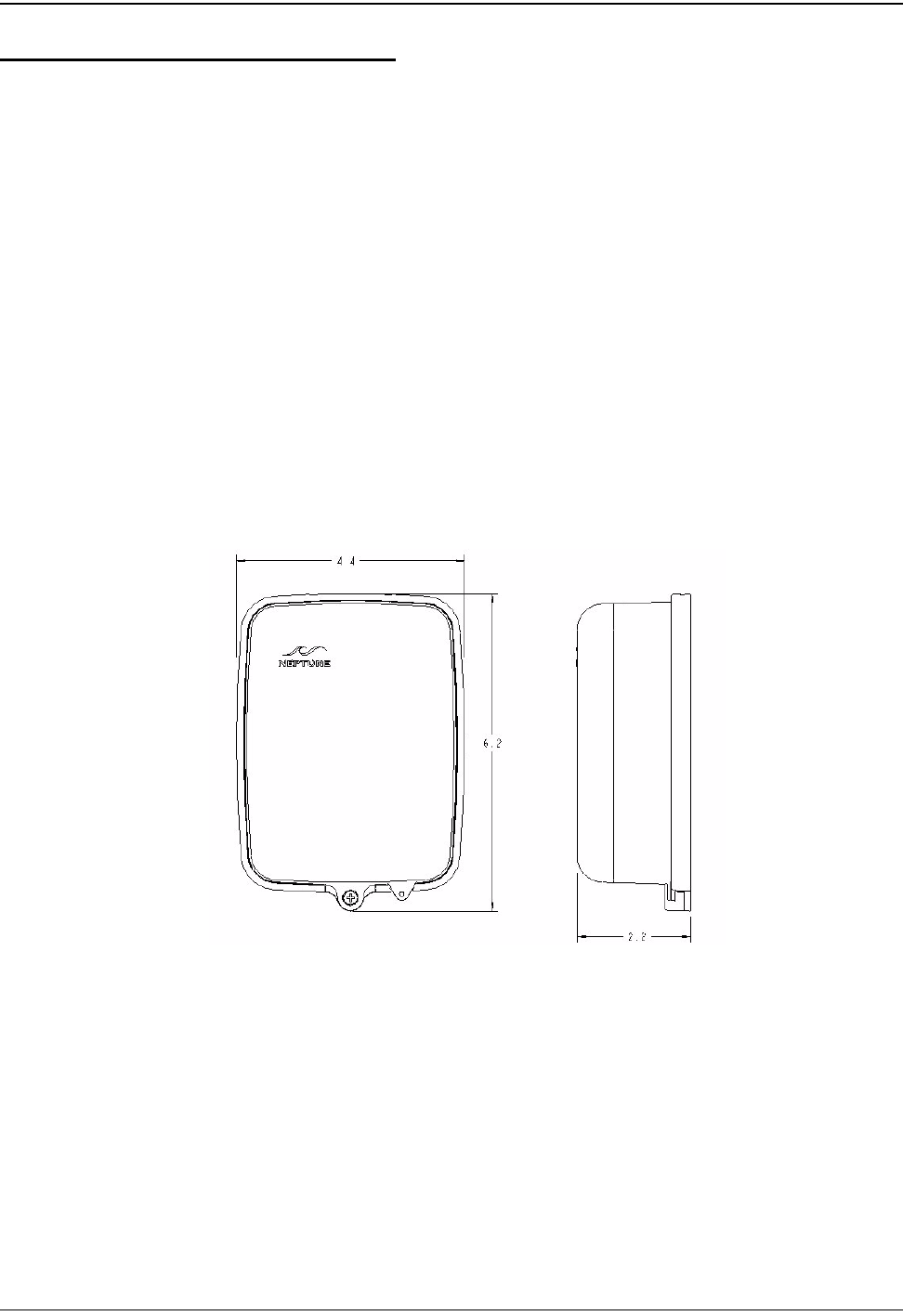
Dimensions and Weight
Figure 4 Wall MIU Dimensions
Operating Temperature -22° to 149°F (-30° to 65°C)
Storage Temperature -40° to 158°F (-40° to 70°C)
Operating Humidity 0 to 95% Condensing
Register Reading 8 digits
MIU ID 9 digits
Dimensions Refer to Figure 4
Weight 1.0 lbs. (454 grams)
R450 Wall and Pit MIU User’s Manual 5
3 General Installation Guidelines
This section describes tools, materials, and general installation information for the
R450 MIU.
Tools and Materials
Tables 1 and 2 show the recommended tools and materials you may need to suc-
cessfully install the R450 MIU or to replace the MIU’s internal battery.
Some items may not apply to your specific installation or the list may not contain all required tools
or materials.
Table 1 Recommended Tools
Item Description/ Recommendation Use
Tool Kit Contains standard tools including:
• Assorted screwdrivers
• Needle-nose pliers
• Wire stripper
• Diagonal cutters
• Electrician’s knife
•Hammer
• Crimping Tool
Part #: 5500-158
Various installation procedures
performed by the utility
Magnet 6 lb. force
Part #: 12287-001
Activating the MIU
Table 2 Recommended Materials
Item Description/Recommendation Use
Cable Solid 3 conductor,
#22 AWG (black/green/red)
Part#: 6431-352
Connecting MIU to encoder
register
Moisture
protection
compound
Novaguard sealant
Part #: 96018-072
Covering exposed wires and termi-
nal screws on register and MIU

General Installation Guidelines
6R450 Wall and Pit MIU User’s Manual
Safety and Preliminary Checks
Observe the following safety and preliminary checks before and during each instal-
lation:
• Verify that you are at the location specified on the Site Work Order.
• Verify that the site is safe for you and your equipment.
• Notify the customer of your presence and tell the customer that you will need
access to the water meter.
• If the Site Work Order does not have an MIU ID number on it, write in the ID
number(s) of the MIU you are about to install. If the Site Work Order already
has an MIU ID number on it, verify that it matches the ID numbers on the MIU
you are about to install.
Verifying/Preparing the Encoder Register
This R450 MIU is designed for use with the following encoder registers:
• ARB III, IV, and V
• ProRead (ARB VI)
• ProRead AutoDetect
• E-Coder (ARB VII)
• Invensys ECRII, ECR III *
*when programmed in ECR II 6-wheel format
Before installing an MIU, the encoder register must be correctly wired and/or pro-
grammed to work with the MIU. ProRead (ARB VI) encoder registers do not
require programming.
Scotchloks Part #: 8138-125 Splicing replacement battery wire
and connecting Wall MIU or
replacement Pit MIU to encoder
register
Site Work Order Documentation provided by your
utility
Receiving and recording informa-
tion about the work site
Table 2 Recommended Materials
Item Description/Recommendation Use
When a ProRead (ARB VI) encoder register is used, the non-AutoDetect ProRead (ARB VI) register
must be programmed for three-wire mode.
General Installation Guidelines
R450 Wall and Pit MIU User’s Manual 7
If connecting the MIU to a new ProRead (ARB VI) encoder register, or if a three-
conductor cable is already connected to a ProRead (ARB VI) encoder register,
ensure that the ProRead (ARB VI) register is programed for three-wire mode using
the ProRead (ARB VI) programmer and its RF/MIU 6, 8, or 10ID TDI format. This
can be accomplished through the ProRead (ARB VI) receptacle before removing
the receptacle.
Installation of at Register (Non Pre-Wired or Potted Only )
1 Before wiring the pit encoder register, make sure the cable is long enough.
Then, when the installation is complete, the pit lid can be removed easily with-
out straining the cable.
2 Use only 22 AWG cable to make the connection from the encoder register to
the MIU.
3 Remove the terminal screw cover from the encoder register.
4 Strip off 3/4” of jacket from the cable, leaving only the three insulated wires.
5 Taking precautions not to nick or cut the insulation on the three wires, strip off
1/2” of insulation from each of the three wires.
Figure 5 Wiring a Neptune Encoder Register
6 If required, connect the 3 conductor wire to the encoder register’s terminals
per the manufacturer’s instructions. See Figure 5 and Table 3.
Table 3 MIU Color Code for Wires
Encoder Register MIU Wire Color/ Encoder Terminal Marking
Neptune ARB® III, IV, and V Black / B Green / G Red / R
Neptune ProRead (ARB VI)
E-Coder (ARB VII)
Black / B Green / G Red / R
ECRII® and ECRIII®Black / R Green / B Red / G
General Installation Guidelines
8R450 Wall and Pit MIU User’s Manual
7 Thread the cable around the strain relief posts of the encoder (Figure 6).
Figure 6 Cable Threaded Around Strain Relief Posts
8 Apply sealant liberally and ensure that it encapsulates the terminal screws and
exposed wires. (See Figure 7).
Neptune requires Novaguard G661 sealant or Dow Corning compound 4.
Figure 7 Application of the Sealant
Any leak point can cause a reading failure in a submerged meter setting.
General Installation Guidelines
R450 Wall and Pit MIU User’s Manual 9
9 Snap the cover onto the encoder register (Figure 8).
Figure 8 Covering the Terminal Screws
10 Run the cable to the MIU, fastening it securely as necessary.
11 If encoder register is pre-wired and potted, use Scotchloks for connecting
register to MIU.
12 Proceed to the section specified for either Pit or Wall installation.
Do not exceed maximum cable lengths as defined in Table 4.
R450 Wall and Pit MIU User’s Manual 10
4 Replacing the MIU Battery (Wall and Pit)
Follow these steps to change-out the pit R450 MIU’s internal battery:
Removing the Battery
1 Slowly remove the pit lid.
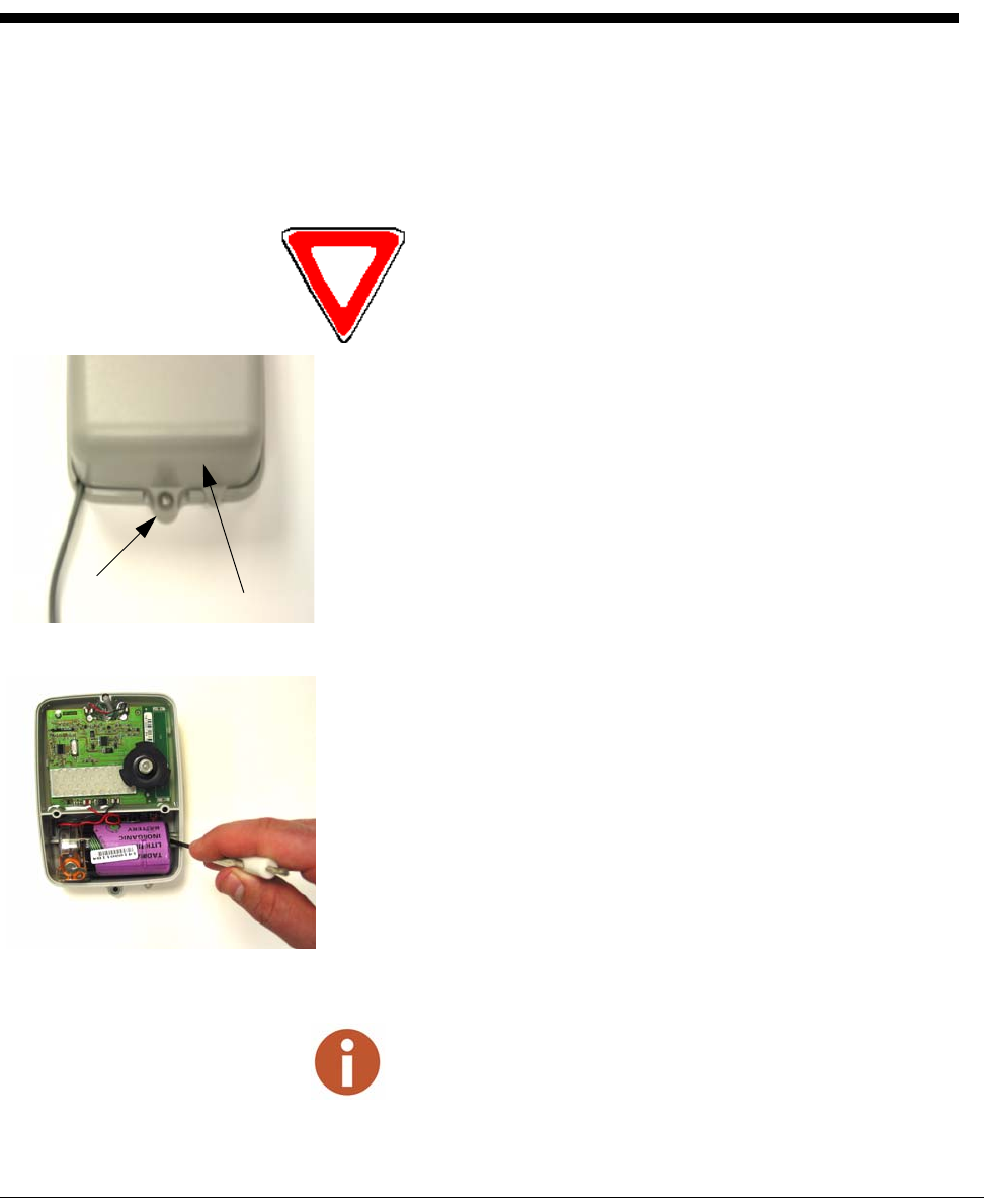
2 Remove the transmitter cover by removing the two Phillips head
crews located inside the back cavity of the main housing.
(See Figure 9.)
3 Lift the transmitter cover from the MIU.
Figure 9 Removing the MIU Transmitter Cover
4 Remove the battery casing from the main housing by inserting a flat-
head screwdriver and dislodging the battery from the battery com-
partment. (See Figure 10.)
Figure 10 The Battery Compartment
Because the MIU is connected to both the antenna
in the pit lid and the meter in the pit base, take care
not to strain the cable when removing the lid.
transmitter cover
screw
When removing the battery, it may be helpful to press on the connected
end while prying the other end.
waterproof connector
antenna
antenna cable
nut
Replacing the MIU Battery (Wall and Pit)
R450 Wall and Pit MIU User’s Manual 11
Cutting and Splicing the Battery Wires
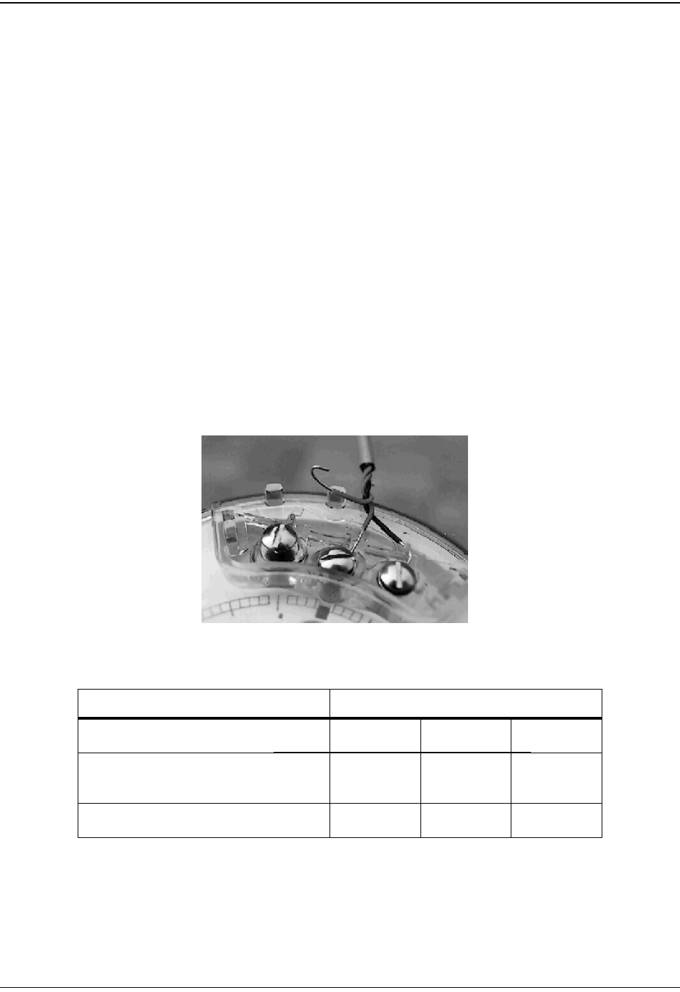
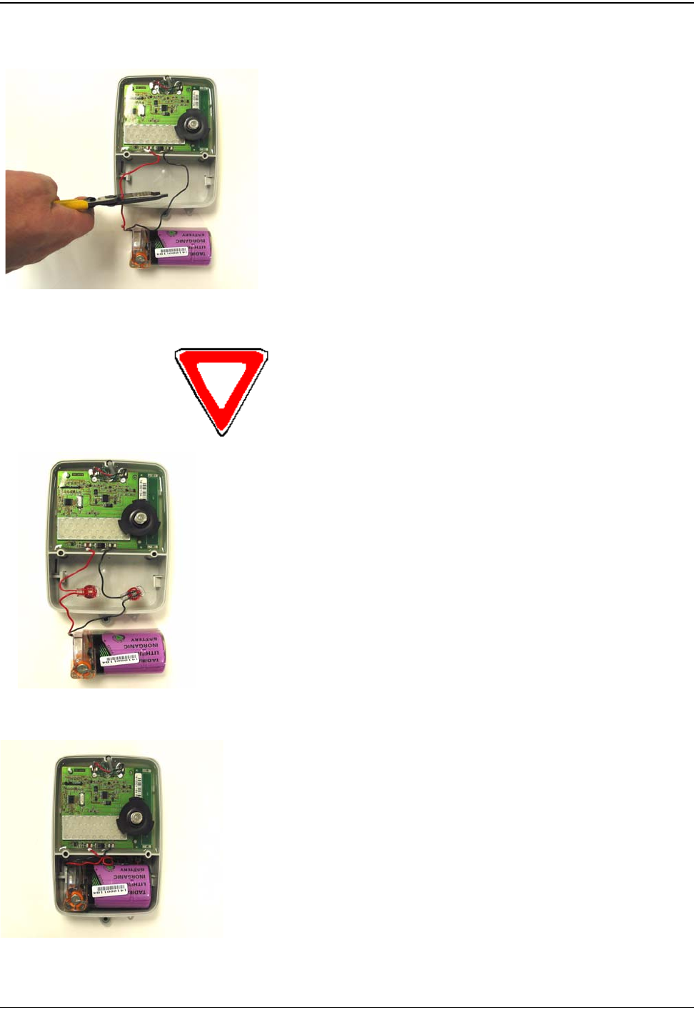
1 As close to the battery casing as possible, cut the battery
connection wires one at a time. See Figure 11.
2 Insert battery wire left in MIU ensuring insulation has not
been compromised.
Figure 11 Cutting the Battery Connection
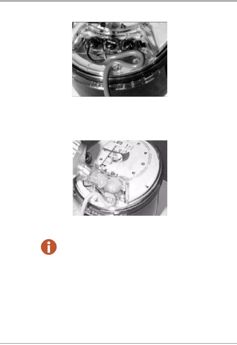
3 Use Scotchlok to splice the wires from the new battery
casing to the wires that were connected to the old battery
casing. See Figure 12.
Figure 12 Splicing the New Battery
4 Be sure to carefully position wires and Scotchloks into
compartment in space available next to battery as shown
in Figure 13, making sure the wires are not pinched when
the battery is snapped into the MIU housing.
Figure 13 Location of Toroid
Cutting the battery connection wires one at a time
prevents shorting.
Ensure the R450 MIU’s black wire is connected to the
black wire on the new battery (-) and the red wire is
connected to the red wire on the new battery (+).
Replacing the MIU Battery (Wall and Pit)
12 R450 Wall and Pit MIU User’s Manual
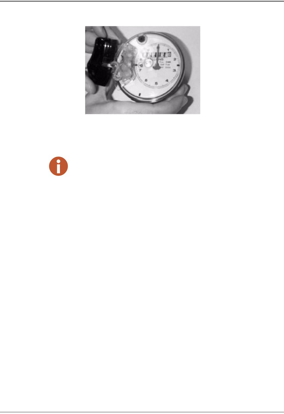
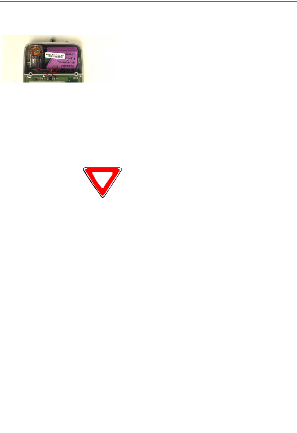
5 Snap the battery casing into the receiving clips on the main
housing. See Figure 14.
Figure 14 Returning Spliced Battery to Main Housing
6 Reactivate the MIU as shown.
Replacing the Transmitter Cover
1 Secure the transmitter cover using the two Phillips head
screws, until the cover is snug and fully seated.
2 Replace the pit lid.
Be careful not to pinch the battery wires between
the cover and the housing.
Replacing the MIU Battery (Wall and Pit)
R450 Wall and Pit MIU User’s Manual 13
Replacement Parts
Table 4 lists the available replacement parts for the R450 MIU.
Table 4 Available Replacement Parts
Part Name Part Number
Solid 3 conductor wire, 22 awg (1000 ft.) 6431-352
Dow Corning #4 compound (5.3oz tube) 96018-064
GE Novaguard (4cc Packet) 96018-072
Scotchloks (UG) 8138-125
Battery Assembly 12213-100
Mounting Adapter 12539-001
Fastener Screw 8328-302
Magnet 12287-001
Antenna 12527-000
Flat Washer 8340-054

Replacing the MIU Battery (Wall and Pit)
Notes:
14 R450 Wall and Pit MIU User’s Manual

R450 Wall and Pit User’s Manual G-1
Glossary
antenna (pit) The MIU antenna used for pit installations.
conical-shaped gasket The cone-shaped rubber gasket on antenna cable used to seal cable
at top of connector housing.
connector housing The black plastic 1/4-turn connector used to waterproof antenna
cable connection to pit MIU.
connector nut The black plastic nut used to depress conical-shaped gasket and seal
antenna cable at the top of connector housing.
flat washer The washer used to seal cable connector housing to pit MIU.
main housing The main body of the MIU that attaches to the mounting adapter.
main housing fastener screw The set screw (Hi-Lo fastener) that holds the main housing to the
mounting adapter.
maximum cable length The length set by the manufacturer for the wire between the encoder
and the remote receptacle. The specifications for this length are
based on a solid 3 conductor wire.
MIU Meter Interface Unit.
mounting adapter The back plate of the MIU that is attached to the wall.
register read time The default time is once an hour for ProRead and 15 minute interval
for E-Coder (ARB VII). Custom time is not available.
seal wire Wire inserted into the seal holes, adjacent to the main housing fas-
tener screw. This seal must be broken to remove the main housing
from the mounting adapter.
serial number A unique identification number given to each MIU at the factory. The
default value is the last programmed plus one. Custom serial numbers
are not available.
strain relief posts Posts located on the encoder register and the back of the main MIU
housing.

Glossary
G-2 R450 Wall and Pit User’s Manual
terminal screw cover The plastic cover on the encoder register that protects the terminal
screws and exposed wires.
terminal screws The screws on the encoder register face that are used to connect and
anchor the three (3) conductor wire to the register.
transmission time The time between MIU transmissions. The default is approximately
fourteen (14) seconds. Custom time is not available.

R450 Wall and Pit User’s Manual I-1
Index
Numerics
3-conductor 13
3-conductor wire 7
3-wire mode 6, 7
A
antenna
care 10
part # 13
B
Battery
replace 10
battery
assembly 13
casing 11, 12
compartment 10
connection 11
internal 5, 10
low, RF emission 1
main housing 12
new 11
remove 10
remove casing 10
replacing 10
wires 11
C
cable 5
3-conductor 7
lengths 2, 9
strain relief posts 8
threaded 8
compound units 1
connect
3-conductor cable 7
3-conductor wire 7
cable 7
encoder register 7
MIU 5, 7
D
description, R450 1
dimensions 3, 4
E
electrical specifications 2
Encoder register
illustrated 7
interface 2
maximum cable length 2
Environmental conditions 3, 4
F
Functional specifications 3, 4
G
gel caps 11
I
Installation
preliminary checks 6
safety 6
Installing
encoder register 7
preparing for 6
insulation
wires 7
L
low battery emissions 1
M
meters
multiple units 1
multiple units 1
O
operating humidity 3, 4
operating temperature 3, 4
P
part numbers 13
product description 1
programmable
non-field programmable 1
R
R450 MIU
description 1
dimensions 3, 4
low battery emissions 1
programming 1
replacement parts 13
tools and materials 5
weight 3, 4

Index
I-2 R450 Wall and Pit User’s Manual
Replacement parts 13
part numbers 13
Replacing 10
replacing the battery 10
RF
frequency control 1
low battery emissions 1
protocol 1
S
ScotchLox 11
serial numbers 1
Specifications
dimensions 3, 4
electrical 2
encoder register interface 2
environmental conditions 3, 4
functional 3, 4
weight 3, 4
splice
wires 11
storage temperature 3, 4
strain relief
posts 8
stripper, wire 5
T
temperature, storage 3, 4
Transmitter specifications 2
U
units
multiple IDs 1
W
weight 3, 4
wire
stripper 5
wires
3 conductor 13
3-conductor 2, 7
3-wire mode 6, 7
battery connection 11
black toroid 11
connected to old battery 11
exposed 5, 8
length 2
MIU color code 7
splicing 11
wires, from battery 11
wiring
correct 6
Neptune encoder register 7
register 7


UM R450 09.06 Part No. XXXXX-XXX © Copyright 2006, Neptune Technology Group Inc. Neptune is a registered trademark of Neptune Technology Group Inc.
neptunetg.com
Neptune Technology Group Inc.
1600 Alabama Highway 229
Tallassee, AL 36078
USA
Tel: (800) 645-1892
Fax: (334) 283-7299
Neptune Technology Group (Canada) Ltd.
7275 West Credit Avenue
Mississauga, Ontario
L5N 5M9
Canada
Tel: (905) 858-4211
Fax: (905) 858-0428
Neptune Technology Group Inc.
Ejército Nacional No. 418
Piso 12, Desp. 1201-1202
Col. Chapultepec Morales
Delegación Miguel Hidalgo
11570 México, Distrito Federal
Tel: (525) 55203 5294 / (525) 55203 5708
Fax: (525) 55203 6503