Ness 106054 RPB Wireless Emergency Button XMTR User Manual users manual
Ness Security Products Pty Ltd. RPB Wireless Emergency Button XMTR users manual
Ness >
users manual
Revision 1
Wireless Security System
Owner's Manual

2
FCC STATEMENT:
THIS DEVICE COMPLIES WITH PART 15 OF THE FCC RULES. OPERATION IS SUBJECT TO THE FOLLOWING TWO CONDITIONS: (1) THIS DEVICE
MAY NOT CAUSE HARMFUL INTERFERENCE, AND (2) THIS DEVICE MUST ACCEPT ANY INTERFERENCE RECEIVED, INCLUDING INTERFERENCE
THAT MAY CAUSE UNDESIRED OPERATION.
NOTE: THE MANUFACTURER IS NOT RESPONSIBLE FOR ANY RADIO OR TV INTERFERENCE CAUSED BY UNAUTHORIZED MODIFICATIONS TO
THIS EQUIPMENT. SUCH MODIFICATIONS COULD VOID THE USER'S AUTHORITY TO OPERATE THE EQUIPMENT.
This equipment generates and uses radio frequency energy and if not installed and used properly, that is, in strict accordance with the manufacturer's
instructions, may cause Interference to radio and television reception. It has been type tested. However, there is no guarantee that interference will
not occur in a particular installation. If this equipment does cause interference to radio or television reception, which can be determined by turning the
equipment off and on, the user is encouraged to try to correct the interference by one or more of the following measures:
• If using an indoor antenna, have a quality outdoor antenna installed.
• Reorient the receiving antenna until interference is induced or eliminated.
• Move the receiver away from the security control.
• Move the antenna leads away from any wire runs to the security control
• Have the device or controller plugged into a different outlet so that it and the receiver are on different branch circuits.
If necessary, the user should consult the dealer or an experienced radio/television technician for additional suggestions. The user or installer may
find a booklet titled "Interference Handbook" prepared by the Federal Communications Commission helpful: This booklet is available from the U.S.
Government Printing Office, Washington, DC 20402. The user shall not make any changes or modifications to the equipment unless authorized by the
Installation Instructions or Users Manual. Unauthorized changes or modifications could void the user's authority to operate the equipment.
“Australia’s largest designer
and manufacturer of
high quality security products”
www.ness.com.au
WARNING
Installation and maintenance shall be performed by
qualified service personnel only.
CAUTION
Risk of explosion if battery is replaced by an
incorrect type. Dispose of used batteries according
to the instructions on the battery.
HEAD OFFICE & MANUFACTURING
Ness Security Products Pty Ltd
ABN 28 069 984 372
4 / 167 Prospect Hwy
Seven Hills NSW 2147 Australia
Ph +61 2 8825 9222 Fax +61 2 9838 8508
ness@ness.com.au
DISTRIBUTED IN USA BY:
The Systems Depot
3266 US Hwy 70 West
Connelly Springs, NC 28612
Ph: 877 254 2172 Fax: 828 397 4212
GUARDPOST Wireless Alarm System with GSM Communicator FCC ID: O2K-106058
Contains GSM/GPRS Modem Transmitter Module FCC ID: MIVGSM0108
Wireless Mini Door & Window Switch Transmitter (RR1) FCC ID: O2K-106064
Wireless Universal Transmitter w/ext input & Vib analyser (RR2) FCC ID: O2K-106065
Wireless 4 Button Keyfob Transmitter (RK4) FCC ID: O2K-106068
Wireless 3 Button Keyfob Transmitter (RK3) FCC ID: O2K-MK304
Wireless 1 Button Bracelet / Neckless Panic Transmitter (RK1) FCC ID: O2K-106050
Wireless Emergency Button Transmitter (RPB) FCC ID: O2K-106054
Wireless Door Bell Button Transmitter (RDB) FCC ID: O2K-106056
Wireless PIR with Pet Immunity (R15PET) FCC ID: O2K-106051
Wireless PIR - Non Pet Immune (R15) FCC ID: O2K-SPIR304
Swivel Mounting Bracket for Wireless PIR FCC ID: N/A
3
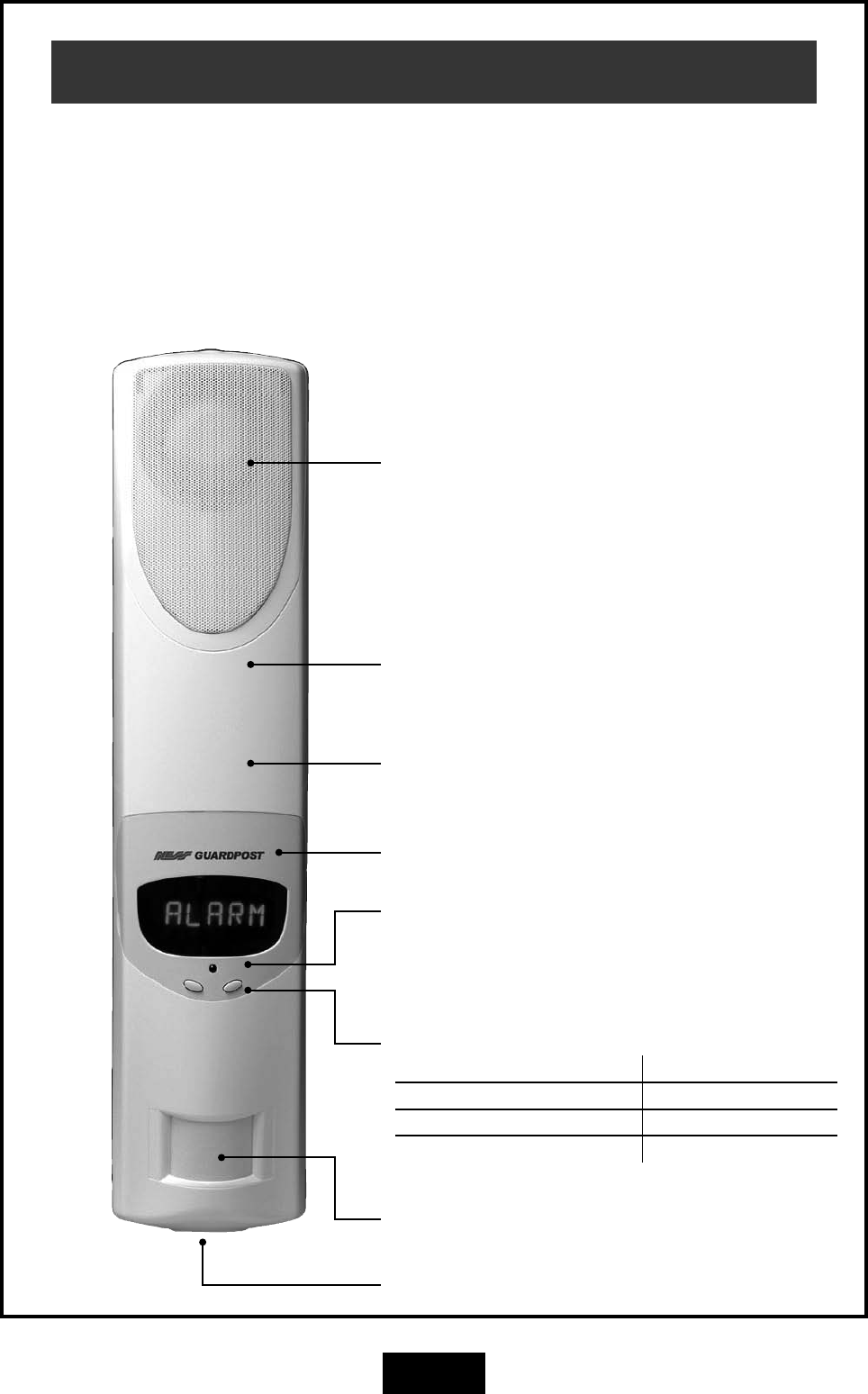
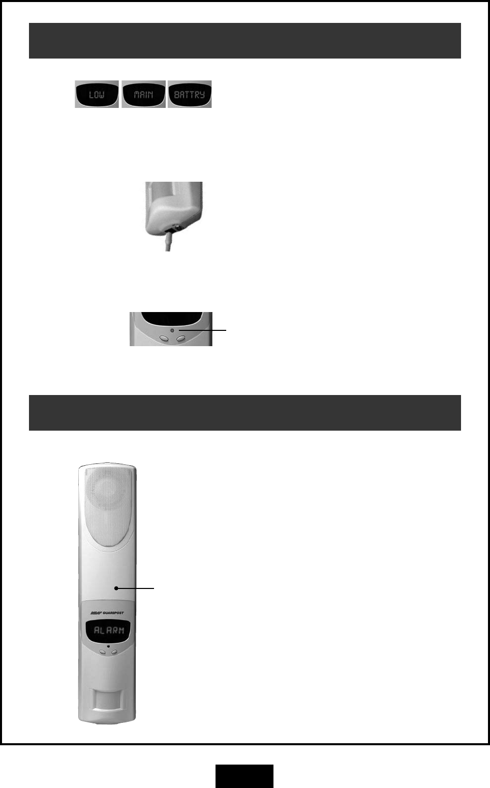
Guardpost Main Unit
onboard siren / Speaker
Siren and spoken voice prompts.
Scrolling LED Display
Indicator LED
One flash every 5 seconds indicates normal
Operation.
Control Buttons
LEFT BUTTON RIGHT BUTTON
Adjust Main Volume - Press x 1 Main Volume 1 – 4
Adjust Bell Type - Press x 2 Bell Type 1 – 3
Adjust Bell Volume - Press x 3 Bell Volume 1 – 4 – OFF
Rechargeable Main Battery
(Internal).
onboard Motion Sensor (PIR)
Emergency over-ride keyswitch
GSM Communicator
(Internal).
Congratulations on selecting GUARDPOST to
protect your family and home.
Your GUARDPOST with its "speak easy"
technology is a revolutionary radio based
state-of-the-art alarm system which has been
built to the highest standards of industrial
design and manufacturing.
The many sophisticated and innovative design
features of the GUARDPOST make the system
highly secure as well as being easy to use.
This Owner's Manual will help you identify the
various parts of your GUARDPOST system
and give you an overview of Operation and
functions.
4
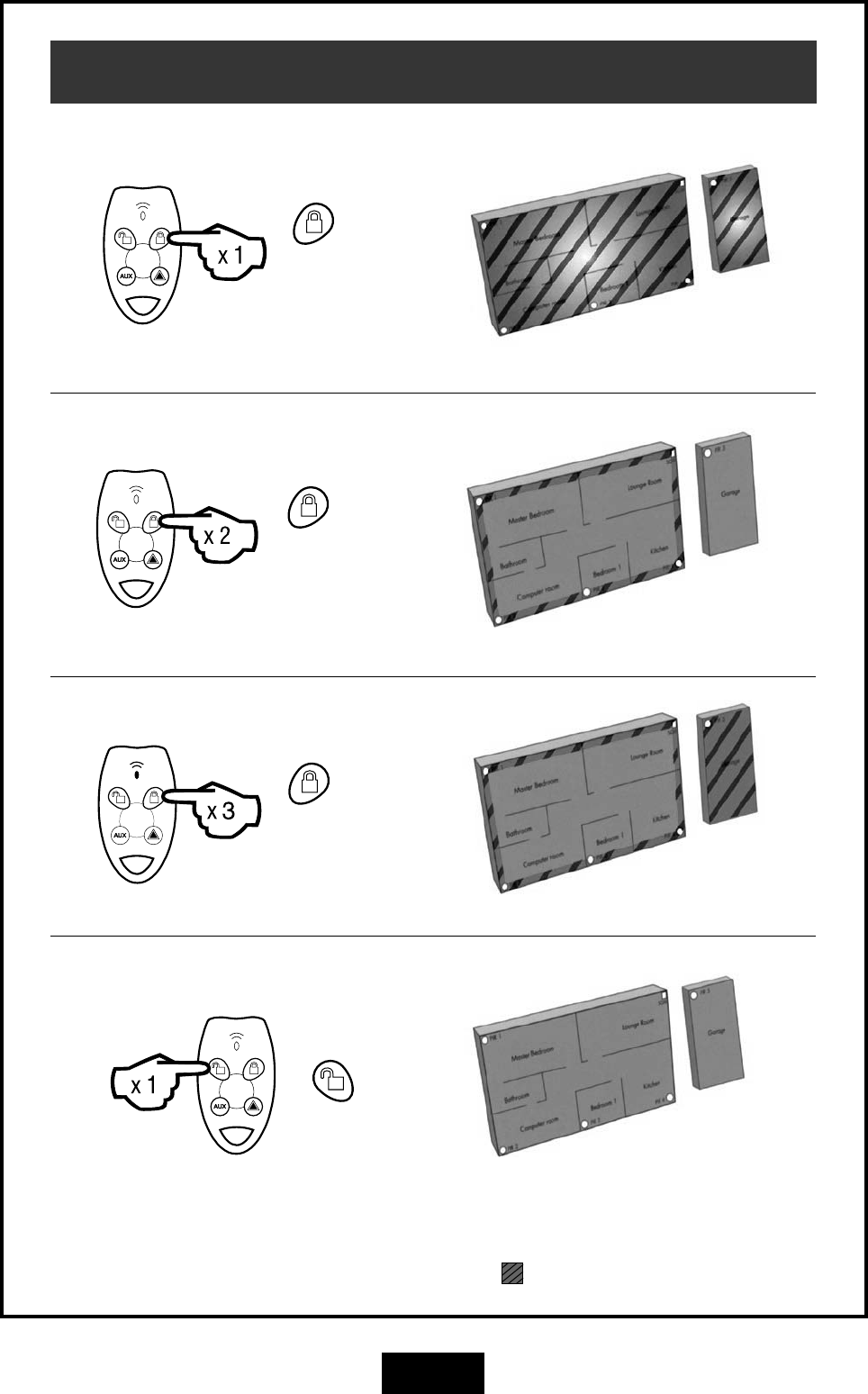
Operation
button
Press once.
ARM
STAY (IF ENABLED)
button
Press twice.
STAY2 (IF ENABLED)
button
Press three
times.
DISARM (OR TO RESET ALARMS)
In these example house plans Armed areas are shown shaed , Disarmed areas shown unshaded.
System is fully armed
System is partially armed
System is partially armed
System is disarmed
button
Press once.
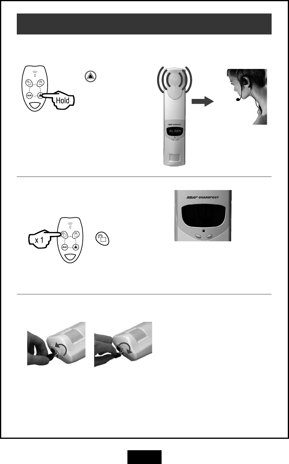
5
button
Press & hold for
4 seconds.
PANIC ALARM
Operation
Central
Monitoring
Station
Alarm
CLEARING DISPLAYS
button
Press once.
To clear any display, press the Disarm
button. To recall the display press
Disarm again, (unless the display has
been reset by arming and disarming.)
EMERGENCY OVER-RIDE KEY
Only to be used if your remote radio
Keys are lost. Insert key and turn
counter-clockwise to disable the
Guardpost. (Store these keys in safe,
hidden place).
GUARDPOST
POWER OFF
Turn the key counter
clockwise.
GUARDPOST
POWER ON
Turn the key clockwise.
GSM
Communicator
6
Main Unit Battery
Connect the charger for 24 hours.
The red Indicator LED will be on while charging.
LOW MAIN BATTERY
(Battery Powered Systems)
If your Guardpost does not run off mains power,
the main battery will provide 3-4 month's Operation
before it must be recharged.
When the "Low Main Battry" message is displayed
you must charge the main battery.
Plug the charger into a 110V mains outlet and plug
the charging connector into the Guardpost for 24
hours.
GSM Cellular Communicator
GSM Communicator
(Internal).
The Guardpost has an onboard GSM communicator
which communicates with your central monitoring
station using the GSM Cellular Telephone Network.
The communicator is setup and programmed by
your installer at the time of installation. It does not
need any maintenance but should be tested when
you perform your regular system test.
The communicator needs an active GSM SIM card
to operate.
LOW MAIN BATTERY
(Mains Powered Systems)
If your Guardpost has a permanent connection to
mains power, the low battery condition may indi-
cate that your Guardpost needs servicing. Contact
your Guardpost installer.
7
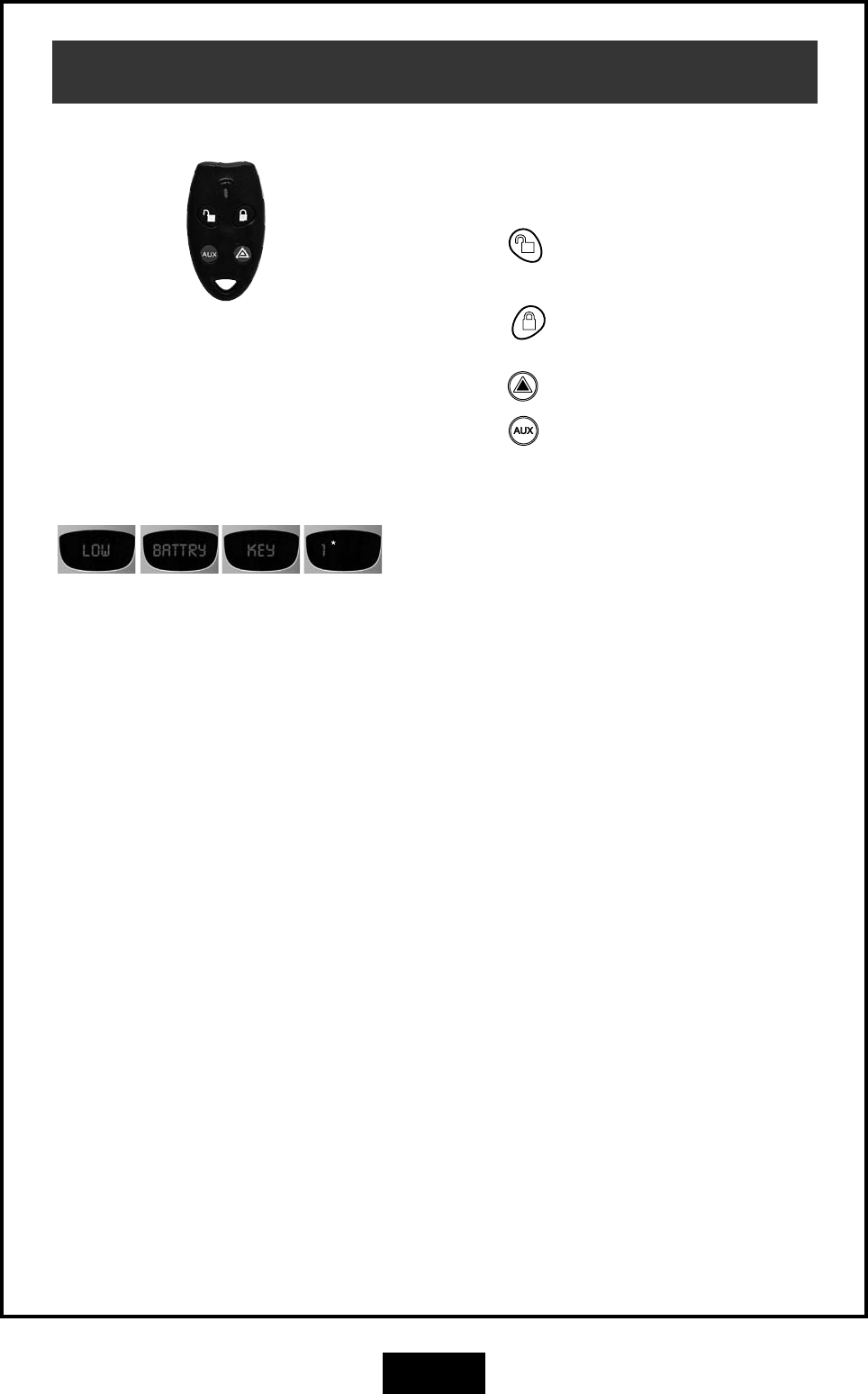
Radio Key (RK4)
OPERATION
RK4 Radio Keys have four buttons for operating your
Guardpost.
Press the button to Disarm the system or to
silence alarms.
Press the button to Arm the system or press
twice for HOME mode (if enabled on your system.)
Press the button to sound the Panic alarm.
Press the button for auxiliary functions as pro-
grammed by your installer.
BATTERY REPLACEMENT
Your RK4 Radio Keys are sealed units with an
expected battery life of 10 years. Low battery warn-
ing might indicate a battery fault or the battery has
been depleted by continuous presses. Contact
your Guardpost dealer for advice.
* Example device
number
8
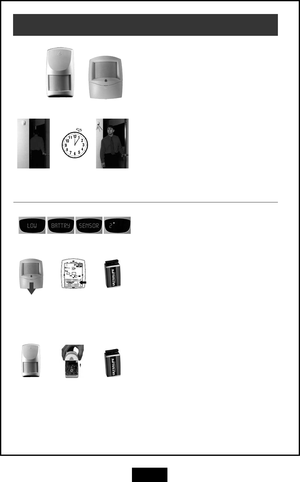
Motion Sensors (PIR)
BATTERY REPLACEMENT
The R12 and R15 use an Ultralife U9VL 9V battery.
Insert the new
battery. Ultralife
U9VL 9V battery
* Example device
number
OPERATION
The R12 and R15 PIR motion sensors can be added
to the system to provide protection in additional
rooms.
Maximum detection range is 40ft for the R12 and
50ft for the R15.
BATTERY SAVING TIMER
The R12 and R15 PIRs have a unique battery sav-
ing feature which means you must wait 5 minutes
between activations.
To test a PIR, leave the room for at least 5 minutes
and then re-enter. The red light in the PIR will flash
to indicate that it has sensed your motion into the
room. If you don't see the red light you may not
have waited long enough - try again.
Leave the
room.
Wait 5
minutes.
Red light
indicates motion
sensed.
Slide battery
compartment
cover down.
R12
The R12 has a sliding battery compartment on the
front of the sensor. Slide the battery compartment
cover downwards to expose the battery.
Insert a new Ultralife U9VL 9V battery and then test
the sensor.
Remove the
battery by
pushing in the
direction of
the arrow.
Insert the
new battery.
Ultralife U9VL
9V battery
Unclip cover
at the bottom.
R15
The R15 battery is inside the sensor. Carefully lift
off the sensor's cover by unclipping at the bottom
using a flat-bladed screwdriver or blunt knife.
Insert a new Ultralife U9VL 9V battery and then test
the sensor.
Remove the
cover.
9
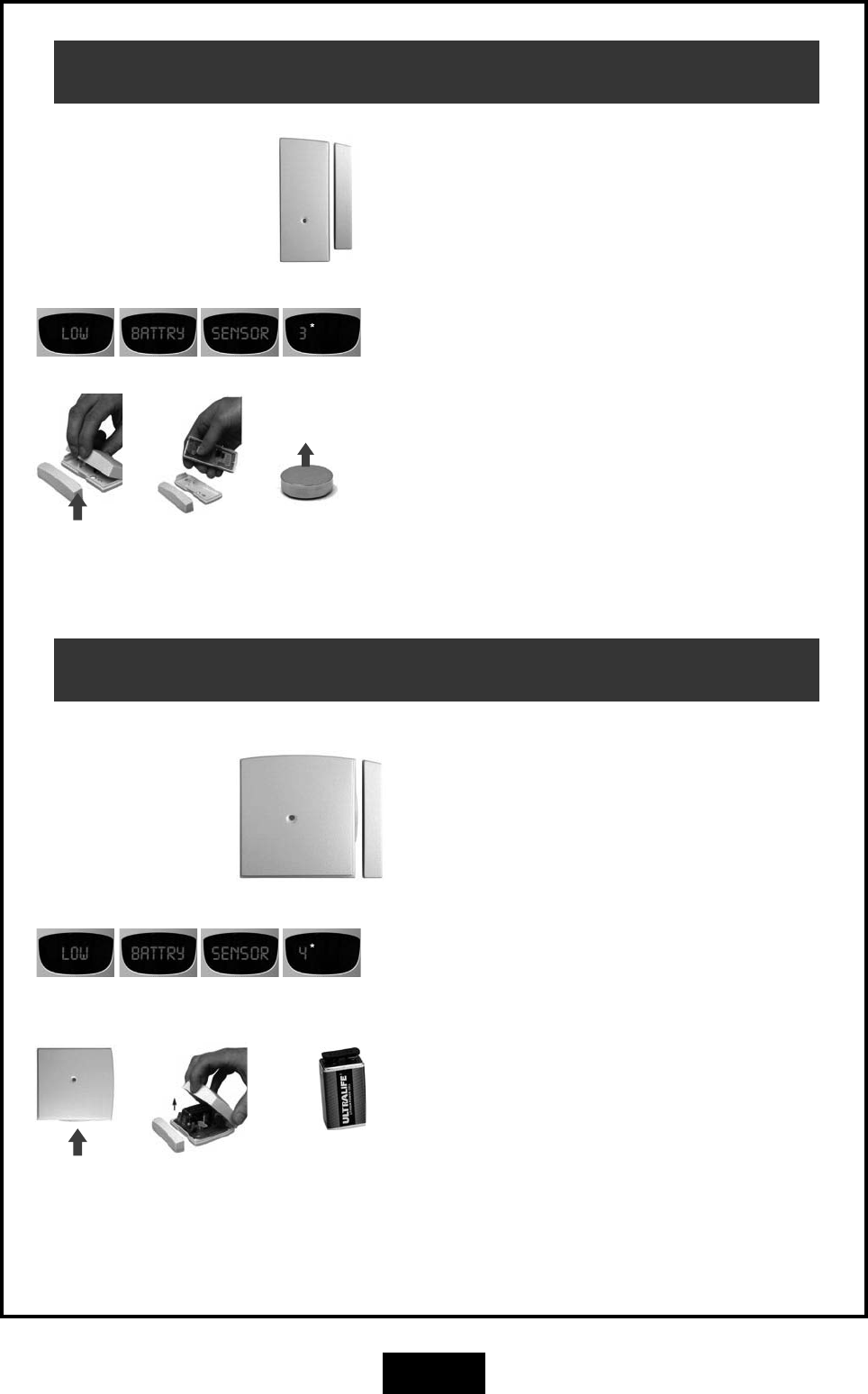
Radio Reed Switch (RR1)
OPERATION
Radio Reed Switches can be installed on windows
and doors to detect opening.
BATTERY REPLACEMENT
Carefully lift off the reed switch cover by unclipping
at the bottom using a flat-bladed screwdriver or
blunt knife.
A warning sound will be heard when opening the
case - this is normal.
Insert a new CR2477 3V Lithium battery and then
test the reed switch.
The new battery must be inserted in the battery clip
with the positive (+) side up.
Open here. Insert the new
battery. CR2477
3V Lithium battery.
Slide
battery out.
Positive (+)
side up.
* Example device
number
Universal Transmitter (RR2)
OPERATION
Universal Transmitters can be used as window and
door switches (same as the Radio Reed Switch) or
as a transmitter for other devices as arranged by
your installer.
BATTERY REPLACEMENT
Carefully lift off the Universal Transmitter cover by
unclipping at the bottom using a flat-bladed screw-
driver or blunt knife.
A warning sound will be heard when opening the
case - this is normal.
Insert a new Ultralife U9VL 9V battery and then test
the transmitter.
Open here. Remove the
cover.
* Example device
number
Insert the
new battery.
Ultralife U9VL
9V battery
10
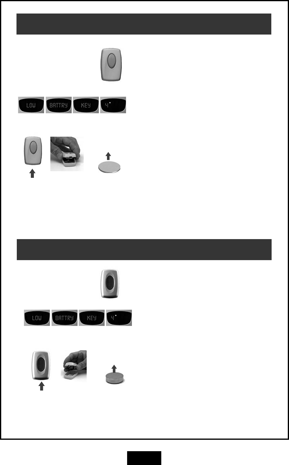
Radio Door Bell (RDB)
OPERATION
Press the Door Bell button to sound the sound the
door chime at the Guradpost main unit.
BATTERY REPLACEMENT
Carefully lift off the RDB Door Bell unit's cover by
unclipping at the bottom using a flat-bladed screw-
driver or blunt knife.
Insert a new CR2032 3V Lithium battery and then
test the sensor.
The new battery must be inserted in the battery clip
with the positive (+) side up.
Open here. Insert the new
battery. CR2032
3V Lithium
battery.
Remove
cover.
Positive (+)
side up.
* Example device
number
Radio Panic Button (RPB)
OPERATION
Press the red Panic button to sound the Panic alarm.
(As programmed by your installer.)
BATTERY REPLACEMENT
Carefully lift off the Panic Button's cover by unclip-
ping at the bottom using a flat-bladed screwdriver
or blunt knife.
Insert a new CR2477 3V Lithium battery and then
test the sensor.
The new battery must be inserted in the battery clip
with the positive (+) side up.
Open here. Insert the new
battery. CR2477
3V Lithium
battery.
Remove
cover.
Positive (+)
side up.
* Example device
number
11
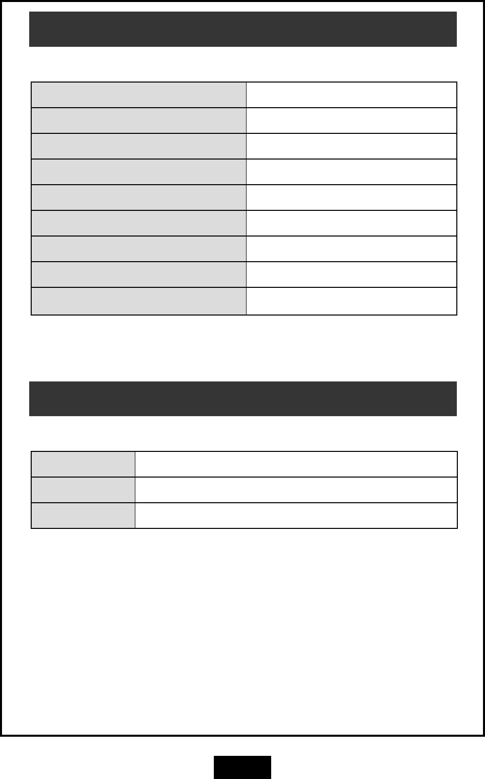
Battery Specifications
GUARDPOST BATTERY SPECIFICATIONS
PART NO. MODEL BATTERY
GUA GUARDPOST MAIN UNIT 12V 3Ah Sealed Lead Acid (Gel) Battery
RK4 Radio Key - 4 button Sealed housing, not user serviceable
R12 R12 PIR Motion Sensor Ultralife U9VL 9V battery
R15 R15 PIR Motion Sensor Ultralife U9VL 9V battery
RPB Radio Panic Button CR2477 3V Lithium battery
RR1 RR1 Radio Reed Switch CR2477 3V Lithium battery
RR2 RR2 Universal Transmitter Ultralife U9VL 9V battery
RDB RDB Radio Door Bell CR2032 3V Lithium battery
Transmitter Specifications
TRANSMITTER SPECIFICATIONS (ALL MODELS)
MODULATION 100% AM (On Off Keyed)
FREQUENCY 303.85 Mhz
POWER < 10uW
NESS GUARDPOST MANUAL This revision May 2007
Document Part Number: 890-370
COPYRIGHT NOTICE
All rights reserved. No part of this publication may be reproduced, transmitted or stored in a retrieval system in any form or by any means, electronic,
mechanical, photocopying, recording, or otherwise, without the prior written permission of Ness.
Ness reserves the right to make changes to features and specifications at any time without prior notification in the interest of ongoing product development
and improvement.
© 2007 Ness Security Products Pty Ltd ABN 28 069 984 372