NetComm Wireless NRB0200 Antenna alignment tool User Manual
NetComm Wireless Limited Antenna alignment tool
User manual
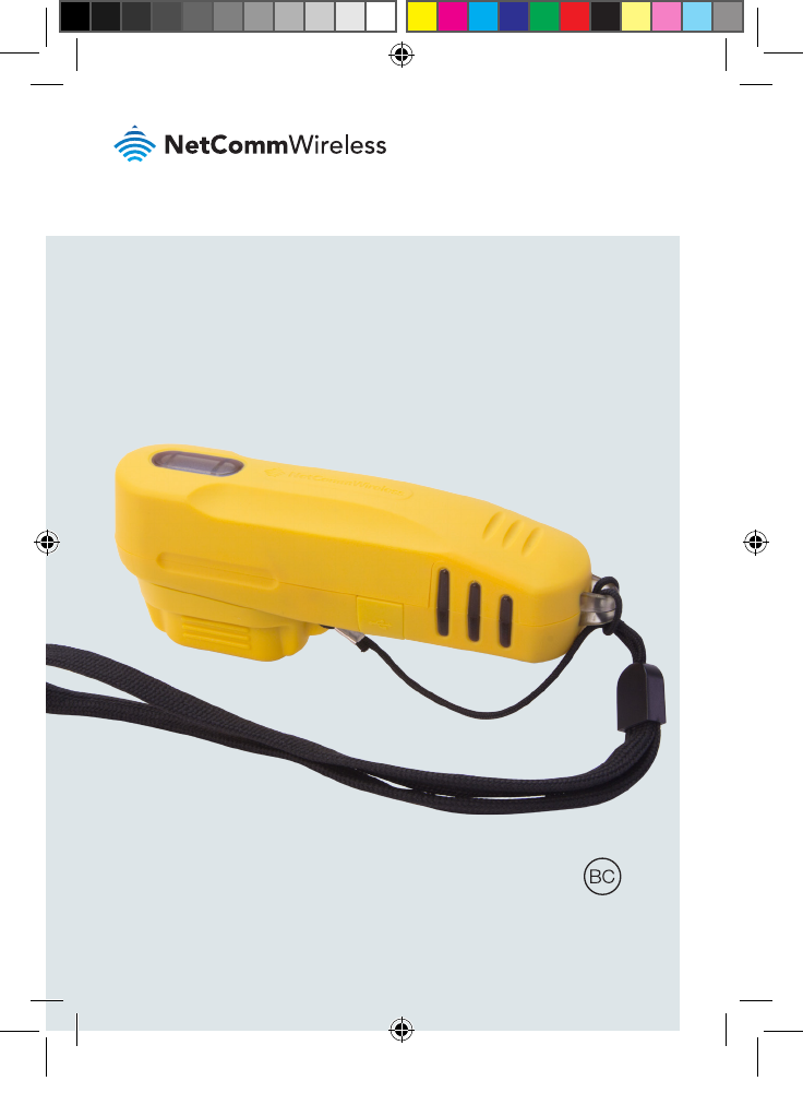
Quick Start Guide
Antenna Alignment Tool
AIMWLLR0-35
QSG-00097 rev 7 AIMWLLR0-35 [NRB-0200] QSG.indd 1 21/12/2016 2:02 PM
| AIMWLLR0-35
2
Welcome
This quick start guide is designed to familiarize you with the features and use of
the NetComm Wireless Antenna Alignment Tool. The Antenna Alignment Tool is
a battery-powered tool which connects to the alignment port on the back of a
NetComm Wireless Outdoor Antenna, providing power and a wireless access
point. The installer can then use a portable wireless device, such as a laptop or
tablet, to connect to the antenna to read signal strength data and align it in the
optimal position.
QSG-00097 rev 7 AIMWLLR0-35 [NRB-0200] QSG.indd 2 21/12/2016 2:02 PM
| AIMWLLR0-35
3
Antenna Alignment Tool
Package contents
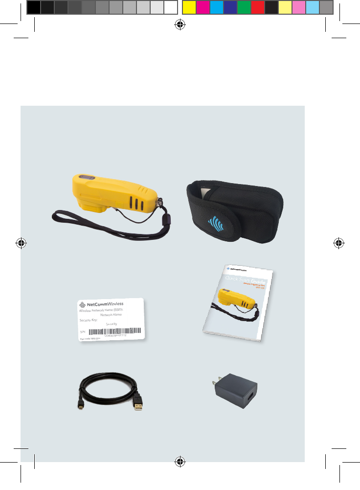
The AIMWLLR0-35 package includes:
1 x AIMWLLR0-35 Antenna
Alignment Tool (in pouch)
1 x Quick Start Guide1 x WiFi security card
1 x Micro USB to Type-A charge cable 1 x AC wall charger (5V/2A)
1 x Antenna Alignment Tool pouch
QSG-00097 rev 7 AIMWLLR0-35 [NRB-0200] QSG.indd 3 21/12/2016 2:02 PM
| AIMWLLR0-35
4
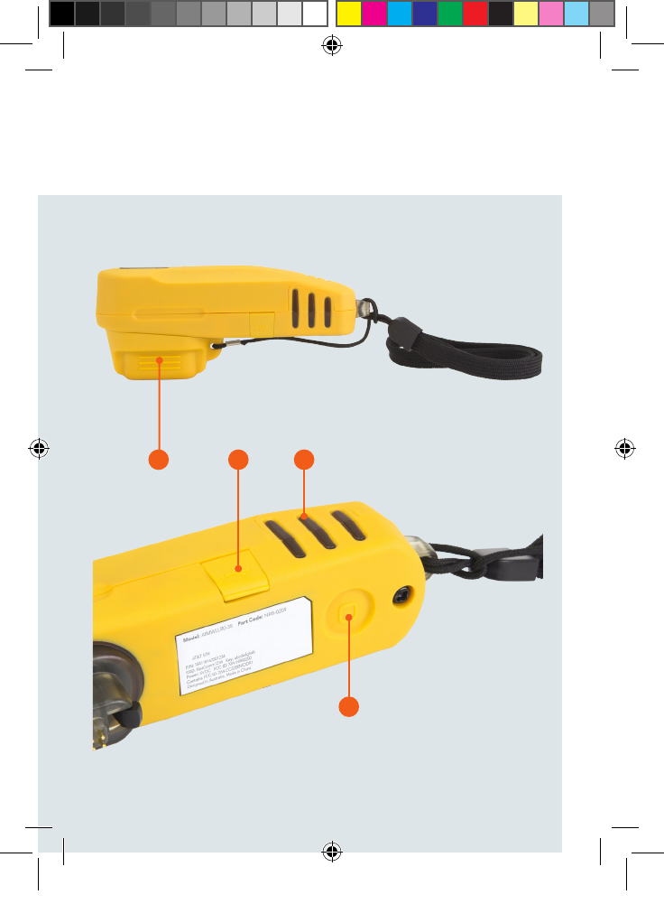
Device overview
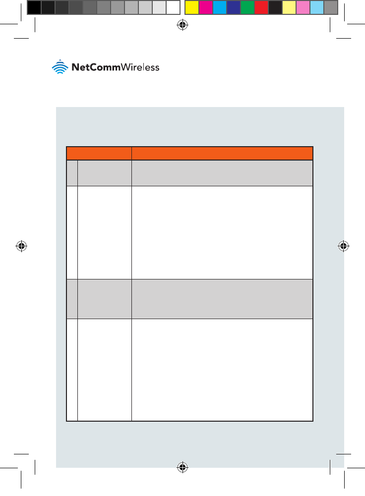
ITEM DESCRIPTION
1Connector
protective cap
Protects the connector from dust and moisture when the
Antenna Alignment Tool is not in use.
2Power button Push once to toggle the Antenna Alignment Tool on and
off. When not connected to the antenna and turned
on, the Antenna Alignment Tool displays the remaining
battery charge level. See the LED indicator section
for details on the battery level indication. When it is
turned on, if it is not connected to the antenna within
approximately 20 seconds, the Antenna Alignment Tool
turns off automatically. When the Antenna Alignment
Tool is disconnected from the antenna, it powers off
automatically.
3Micro USB
port to charge
the battery
The Micro USB port connects to a USB power source
using the supplied USB cable to charge the internal
battery. Connect the Antenna Alignment Tool to a 5V/2A
power source for optimum charging speed.
4Multipurpose
LED indicators The LED indicators on the Antenna Alignment Tool are
multifunctional. They display:
1. Remaining battery level when the battery check
button is pressed or the unit is charging (Battery
check mode)
2. RF signal strength during alignment (Cell scanning
mode)
3. System status when the outdoor antenna is in
normal operation (Normal operation mode).
See the LED indicator section for more information.
QSG-00097 rev 7 AIMWLLR0-35 [NRB-0200] QSG.indd 4 21/12/2016 2:02 PM
| AIMWLLR0-35
5
Antenna Alignment Tool
1 3
2
4
QSG-00097 rev 7 AIMWLLR0-35 [NRB-0200] QSG.indd 5 21/12/2016 2:02 PM
| AIMWLLR0-35
6
Charging the Antenna
Alignment Tool
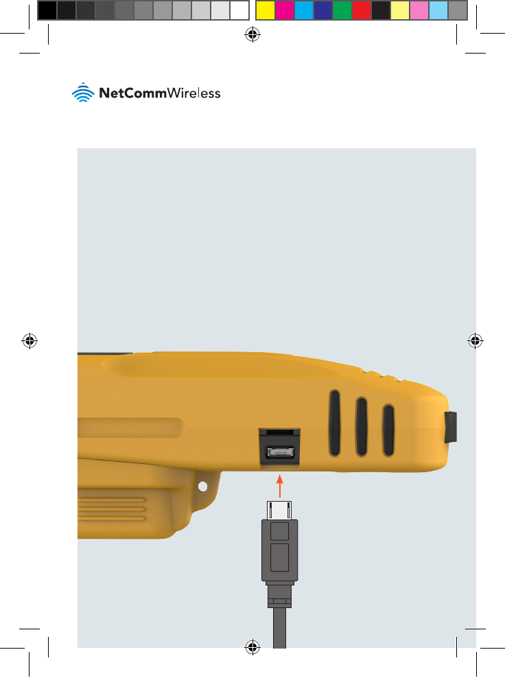
The included USB cable can be used to charge the Antenna Alignment Tool.
Connect the USB cable from the Micro USB port on the Antenna Alignment Tool
to the included AC wall charger or another 5V/2A power source for optimum
charging speed. The LED indicators on the side of the Antenna Alignment Tool
light up and may ash depending on the remaining battery level. See the LED
indicator section for details on reading the battery level.
QSG-00097 rev 7 AIMWLLR0-35 [NRB-0200] QSG.indd 6 21/12/2016 2:02 PM
| AIMWLLR0-35
7
Antenna Alignment Tool
Checking the remaining
battery level
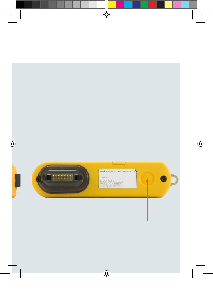
Press the Power button once. The Antenna Alignment Tool goes into Battery
check mode and the LED indicators light up according to the description in the
LED indicators section of this guide.
QSG-00097 rev 7 AIMWLLR0-35 [NRB-0200] QSG.indd 7 21/12/2016 2:02 PM
| AIMWLLR0-35
8
LED Indicators
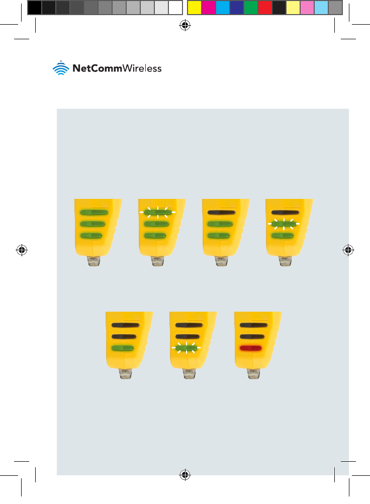
The LED indicators display different things depending on the mode of the Antenna
Alignment Tool.
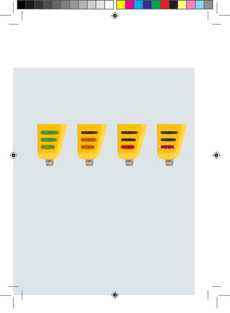
a) Battery check mode – When the power button is pressed or the battery is
charging.
95-100% 80-94% 65-79% 50-64%
35-49% 20-34% 0-19%
QSG-00097 rev 7 AIMWLLR0-35 [NRB-0200] QSG.indd 8 21/12/2016 2:02 PM
| AIMWLLR0-35
9
Antenna Alignment Tool
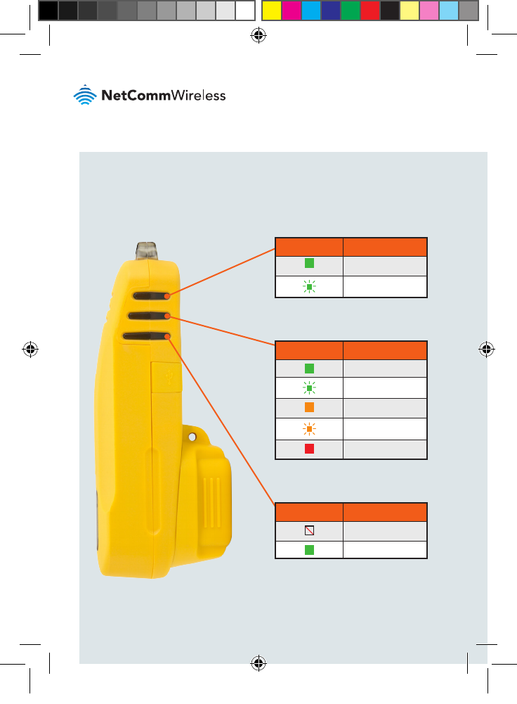
b) Cell scanning mode - When the Antenna Alignment Tool is connected to
an Outdoor Antenna.
Strong signal Medium signal Low signal No cell detected
QSG-00097 rev 7 AIMWLLR0-35 [NRB-0200] QSG.indd 9 21/12/2016 2:02 PM
| AIMWLLR0-35
10
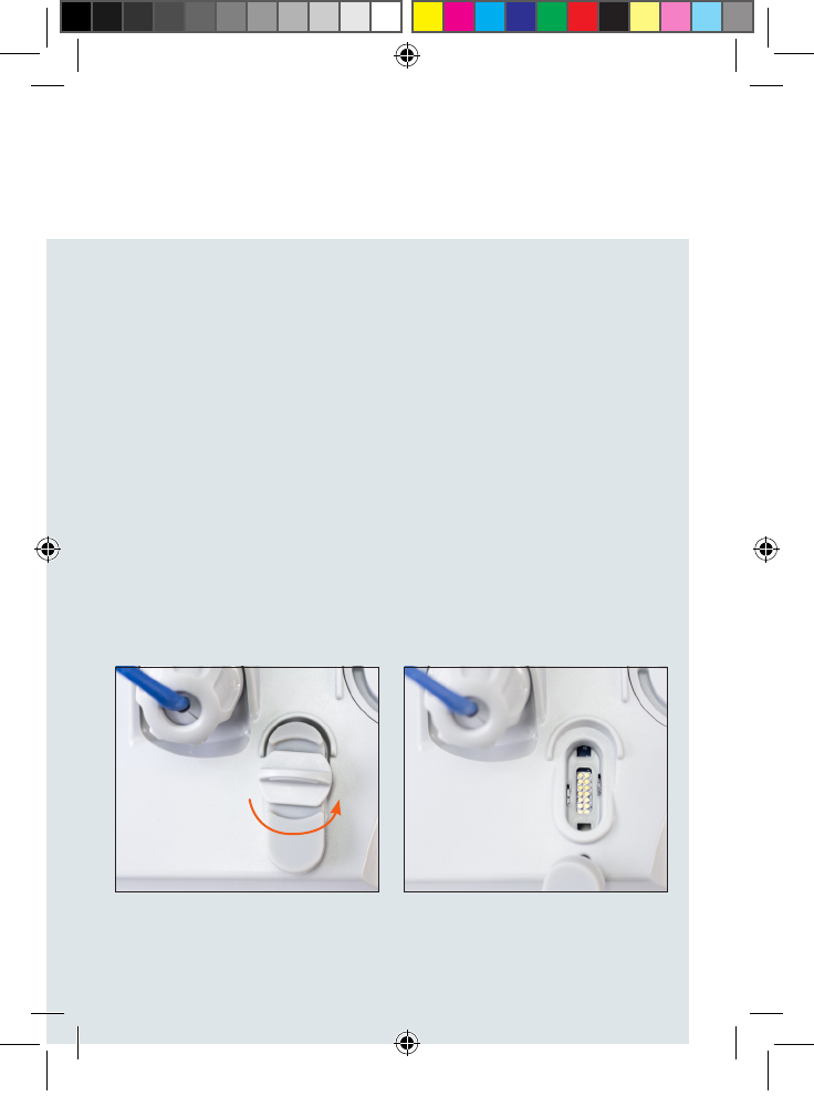
c) Normal operation mode – When the Antenna Alignment Tool is connected
to an Outdoor Antenna.
LED 1 indicates the Ethernet
connection status of the antenna.
LED 1 DESCRIPTION
Link is up
Activity on Ethernet
LED 2 indicates the Cellular
connection status of the antenna.
LED 2 STATUS DESCRIPTION
Data APN attached
Data APN attaching
LTE registered
LTE registering
LTE not registered
LED 3 indicates the Power status of
the antenna.
LED 3 STATUS DESCRIPTION
No power
Power on
QSG-00097 rev 7 AIMWLLR0-35 [NRB-0200] QSG.indd 10 21/12/2016 2:02 PM
| AIMWLLR0-35
11
Antenna Alignment Tool
Before beginning to align an outdoor antenna, press the battery check button on
the bottom of the Antenna Alignment Tool and observe the battery level indicated
by the LED indicators. Ensure that you have an adequate charge level for the
installation.
To align an outdoor antenna:
1. Prepare the outdoor antenna as per the Installation Guide.
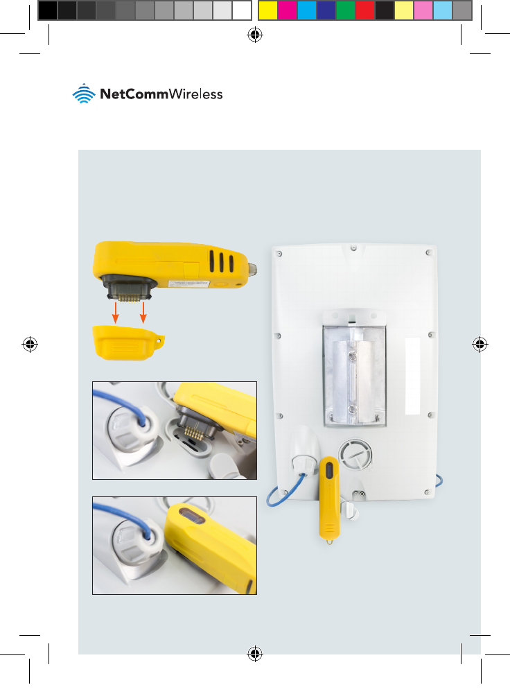
2. On the outdoor antenna, locate the alignment port and remove the
protective cap from it.
Using the Antenna
Alignment Tool to align
an outdoor antenna
QSG-00097 rev 7 AIMWLLR0-35 [NRB-0200] QSG.indd 11 21/12/2016 2:02 PM
| AIMWLLR0-35
12
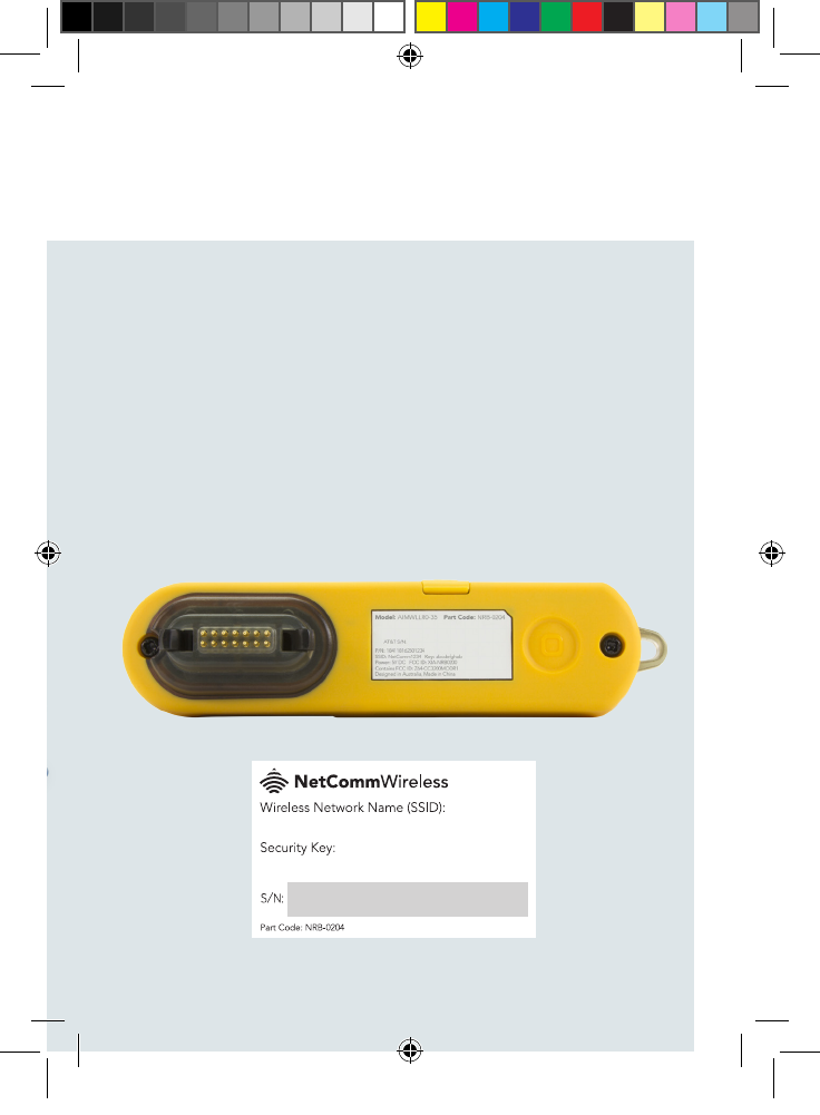
3. Remove the protective cap from the Antenna Alignment Tool’s connector
then connect the Antenna Alignment Tool to the alignment port of the
antenna as shown below.
4. When the device is positioned at the mounting location, press the Antenna
Alignment Tool’s Power button once to turn it on.
QSG-00097 rev 7 AIMWLLR0-35 [NRB-0200] QSG.indd 12 21/12/2016 2:02 PM
| AIMWLLR0-35
13
Antenna Alignment Tool
5. Wait approximately 1 minute for the antenna to go through its boot
up process.
6. Using a portable wireless device such as a laptop or tablet, scan for
nearby wireless networks. Connect to the network being broadcast by
the Antenna Alignment Tool using the Network Name and Password
which are printed on the label and on the WiFi security card included
in the package. When the wireless connection has been established,
use your wireless device to browse to the IP address of the antenna.
To complete the installation, follow the Installation Guide that comes
with your outdoor antenna.
NOTE: When the Antenna Alignment Tool is connected to the Outdoor Antenna, do not point
the front panel of the antenna directly at other people or yourself. Always maintain a separation
distance of 8 inches between any part of your body and the front of the antenna (the ofcial
FCC recommendation species 20cm separation). We recommend that you disconnect the
PoE cable and Antenna Alignment Tool if you are working in proximity to the antenna and it is
not required to be on.
QSG-00097 rev 7 AIMWLLR0-35 [NRB-0200] QSG.indd 13 21/12/2016 2:02 PM
| AIMWLLR0-35
14
RF Exposure
The AIMWLLR0-35 contains a transmitter and a receiver. When it is on, it receives
and transmits RF energy. When you communicate with your device, the system
handling your connection controls the power level at which your device transmits.
The AIMWLLR0-35 meets the government’s requirements for exposure to radio
waves. It is designed and manufactured not to exceed the emission limits for
exposure to radio frequency (RF) energy set by the Federal Communications
Commission of the U.S. Government.
The AIMWLLR0-35 complies with radio frequency (RF) exposure limits adopted
by the Federal Communications Commission for an uncontrolled environment.
This equipment should be installed and operated with minimum distance 20 cm
between the radiator & your body.
The approved module is being used in this device.
This product contains FCC ID: XIA-NRB0200
QSG-00097 rev 7 AIMWLLR0-35 [NRB-0200] QSG.indd 14 21/12/2016 2:02 PM
| AIMWLLR0-35
15
Antenna Alignment Tool
FCC Statement
FCC compliance
Federal Communications Commission Notice (United States): Before a wireless
device model is available for sale to the public, it must be tested and certied to
the FCC that it does not exceed the limit established by the government-adopted
requirement for safe exposure.
FCC regulations
This device complies with part 15 of the FCC Rules. Operation is subject to the
following two conditions: (1) This device may not cause harmful interference, and
(2) this device must accept any interference received, including interference that
may cause undesired operation.
This device has been tested and found to comply with the limits for a Class B
digital device, pursuant to Part 15 of the FCC Rules. These limits are designed
to provide reasonable protection against harmful interference in a residential
installation. This equipment generates, uses and can radiate radio frequency
energy and, if not installed and used in accordance with the instructions,
may cause harmful interference to radio communications. However, there is
no guarantee that interference will not occur in a particular installation. If this
equipment does cause harmful interference to radio or television reception, which
can be determined by turning the equipment off and on, the user is encouraged to
try to correct the interference by one or more of the following measures:
Reorient or relocate the receiving antenna.
Increase the separation between the equipment and receiver.
Consult the dealer or an experienced radio/TV technician for help.
Changes or modications not expressly approved by the party responsible for
compliance could void the user‘s authority to operate the equipment.
QSG-00097 rev 7 AIMWLLR0-35 [NRB-0200] QSG.indd 15 21/12/2016 2:02 PM
QSG-00097 rev6
Product Warranty
For warranty information please visit
http://www.netcommwireless.com/
Safety and product care
Please refer to the user guide for safety and product care information.
NETCOMM WIRELESS LIMITED ABN 85 002 490 486
Head Ofce, 18-20 Orion Road
Lane Cove, Sydney, NSW 2066, Australia
p: +61 2 8205 3888 f: +61 2 9424 2010
e: sales@netcommwireless.com
www.netcommwireless.com
QSG-00097 rev 7 AIMWLLR0-35 [NRB-0200] QSG.indd 16 21/12/2016 2:02 PM