NetComm Wireless NTC140W 4G WiFi M2M Router User Manual
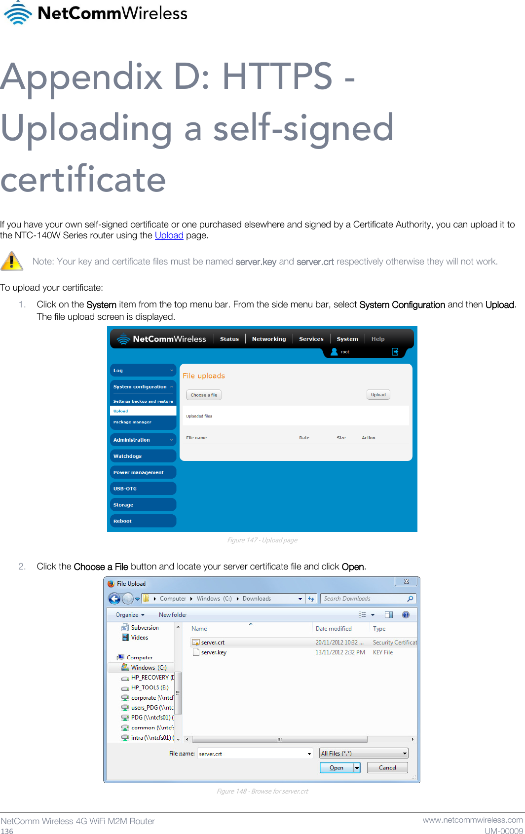
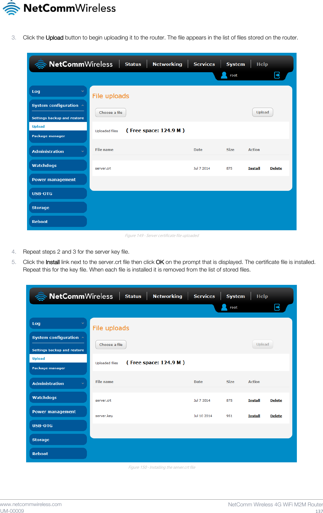
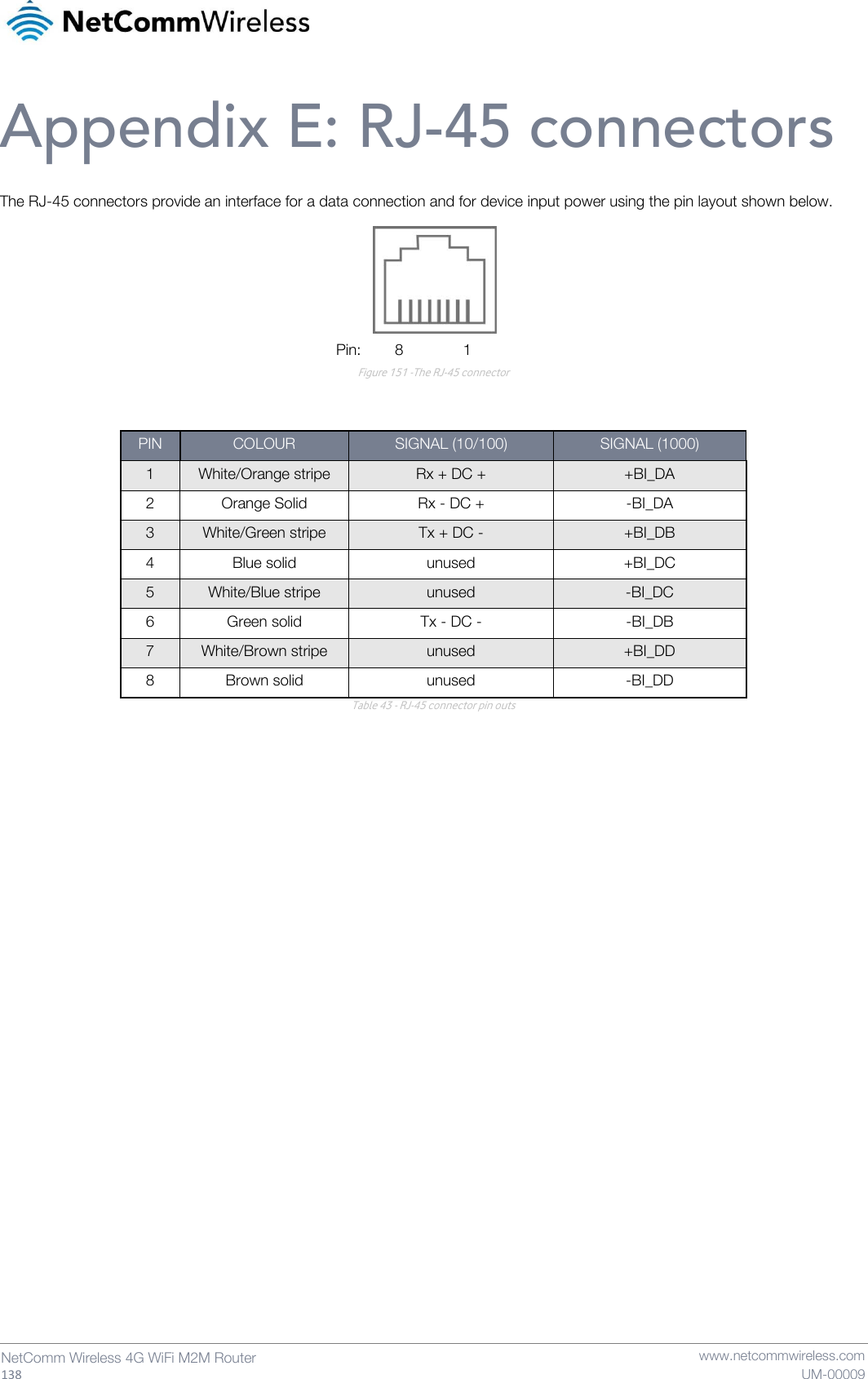
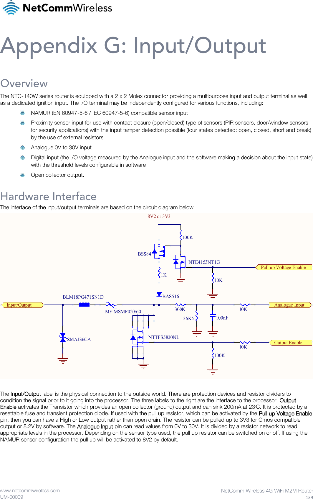
NetComm Wireless Limited 4G WiFi M2M Router
UserManual.wiki
>
NetComm Wireless
>
NTC140W User Manual
>
User Manual
Contents
1.
User Manual
2.
Users Manual
User Manual
Navigation menu
Upload a User Manual
Namespaces
Wiki Guide
HTML
PDF
Info
Views
User Manual
Discussion / Help
Navigation

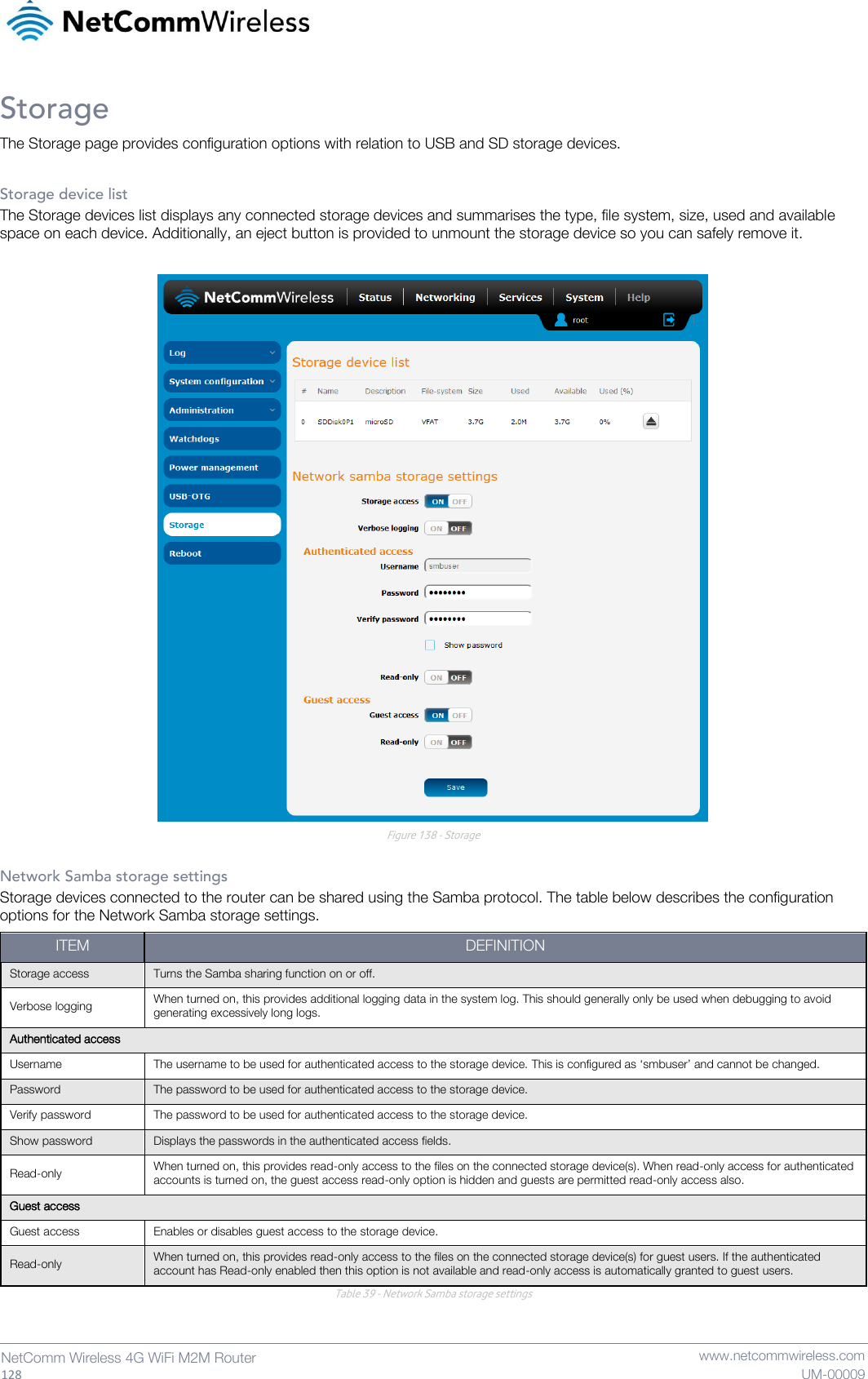
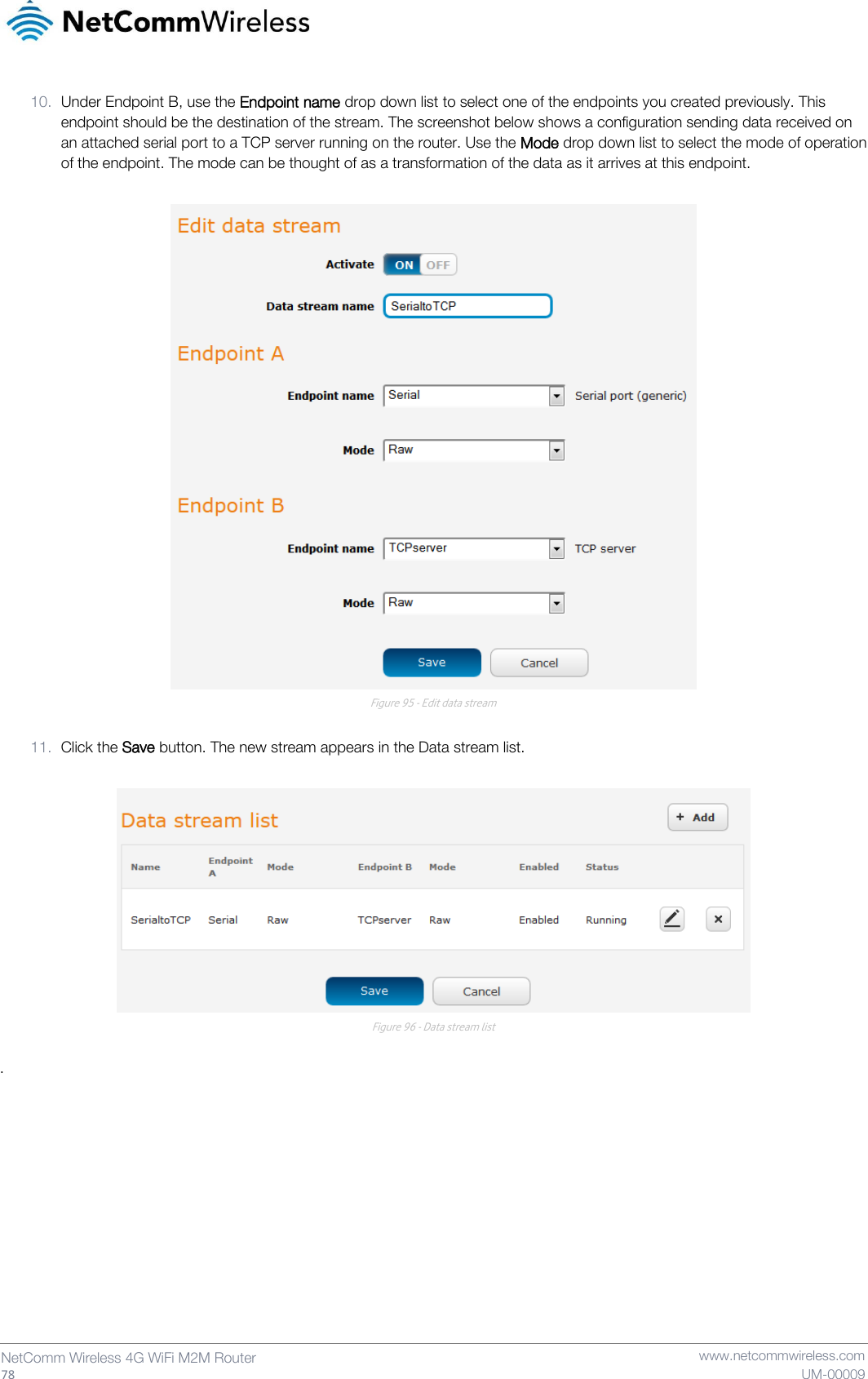
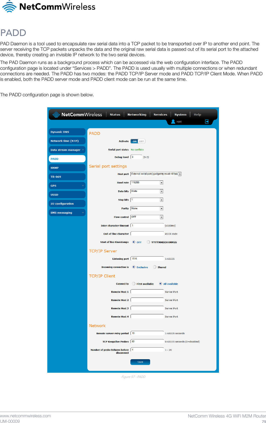
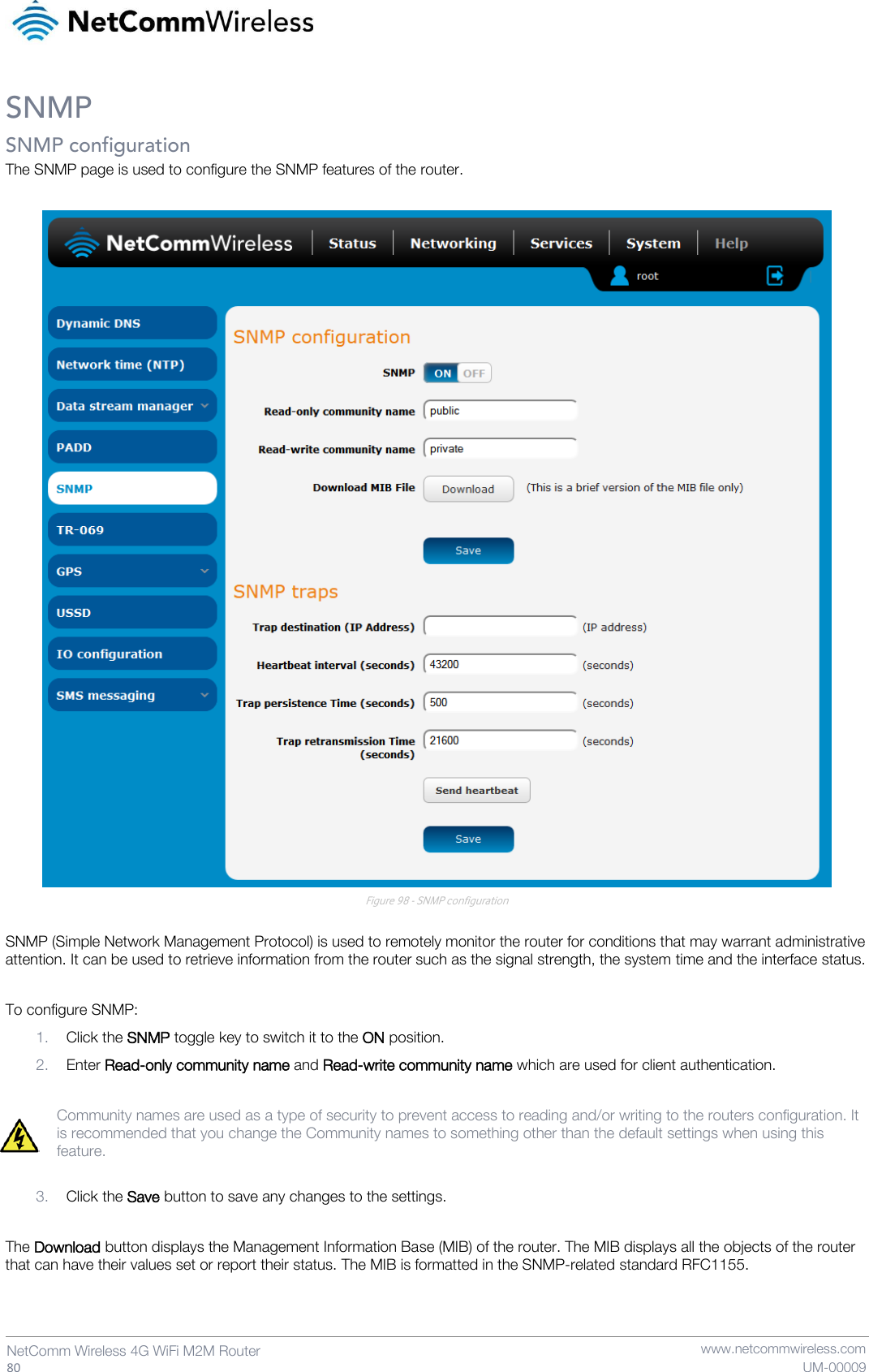
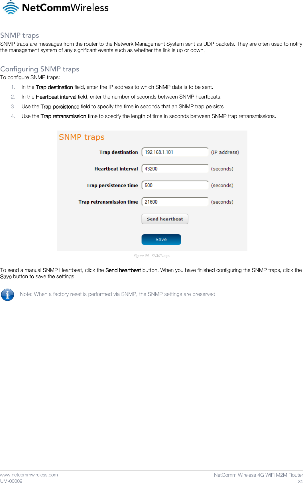
![58 NetComm Wireless 4G WiFi M2M Router www.netcommwireless.com UM-00009 5. Enter the details of the rule in the section that is displayed and click the Save button. Figure 68 - MAC / IP / Port filtering settings OPTION DESCRIPTION Bound Use the drop down list to select the direction of the traffic for which you want to apply to the rule. Inbound refers to all traffic that is entering the router including data entering from the WAN and the LAN. Outbound refers to all traffic exiting the router including traffic leaving in the direction of the WAN and traffic leaving in the direction of the LAN. Forward specifies traffic that enters on the LAN or WAN side and is forwarded to the opposite end. Protocol Use the drop down list to select the protocol for the rule. You can have the rule apply to All protocols, TCP, UDP, UDP/TCP or ICMP. Source MAC Address Enter the MAC address in six groups of two hexadecimal digits separated by colons (:). e.g. 00:40:F4:CE:FA:1E Source IP Address Enter the IPv4 address that the traffic originates from and the subnet mask using CIDR notation. Destination IP Address Enter the IPv4 address that the traffic is destined for and the subnet mask using CIDR notation. Action Select the action to take for traffic which meets the above criteria. You can choose to Accept or Drop packets. When the default rule is set to Accept, you cannot create a rule with an Accept action since the rule is redundant. Likewise, if the default rule is set to Dropped you cannot create a rule with a Drop action. Comment [Optional] Use this field to enter a comment as a meaningful description of the rule. Table 22 - Current MAC / IP / Port filtering rules in effect 6. The new rule is displayed in the filtering rules list. You can edit the rule by clicking the Edit button or delete the rule by clicking the button. Figure 69 - Completed filtering rule](https://usermanual.wiki/NetComm-Wireless/NTC140W.User-Manual/User-Guide-2415699-Page-58.png)
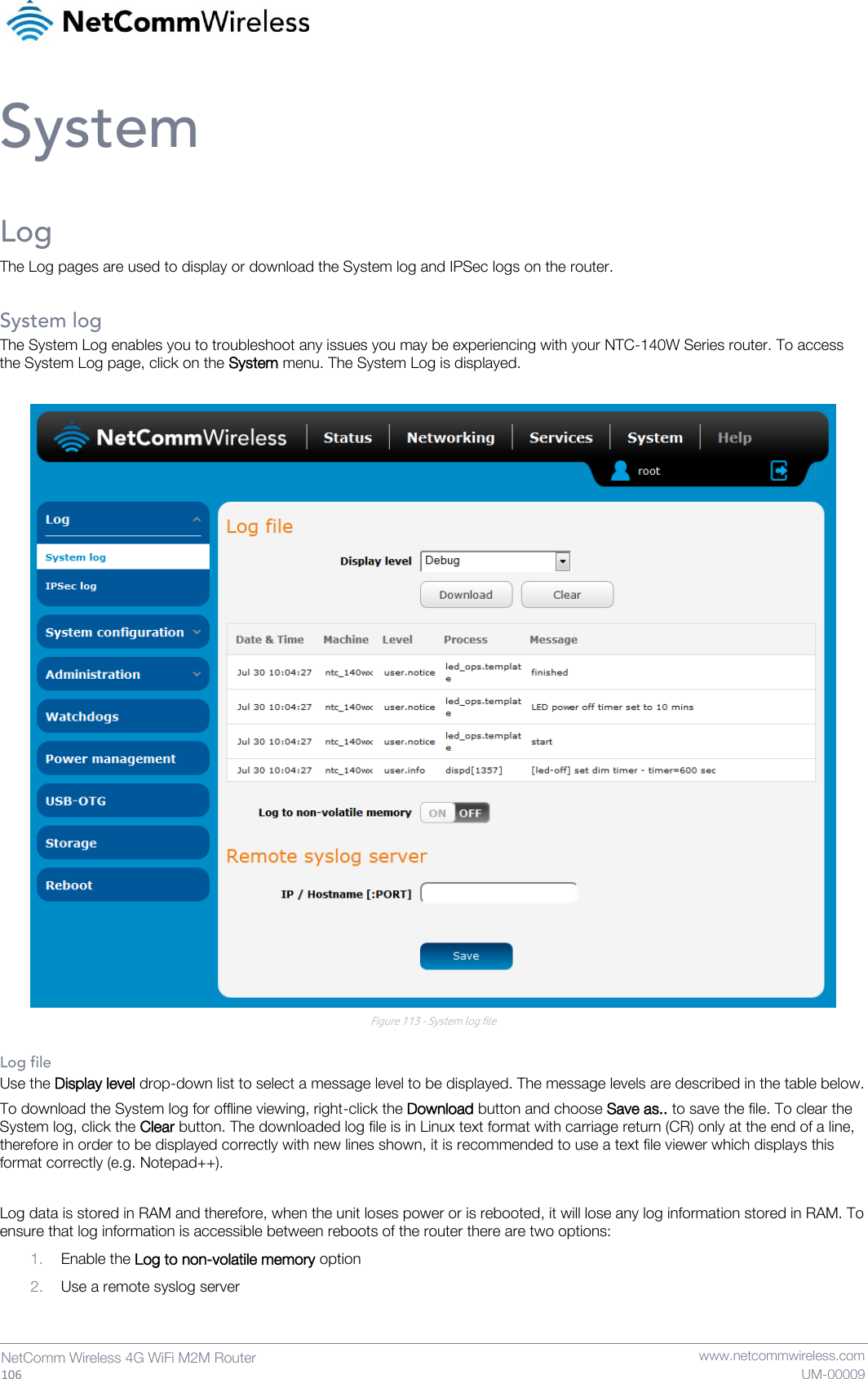
![www.netcommwireless.com NetComm Wireless 4G WiFi M2M Router 107 UM-00009 Enable the log to non-volatile memory option When the router is configured to log to non-volatile memory, the log data is stored in flash memory, making it accessible after a reboot of the router. Up to 512kb of log data will be stored before it is overwritten by new log data. Flash memory has a finite number of program-erase operations that it may perform to the blocks of memory. While this number of program-erase operations is quite large, we recommend that you do not enable this option for anything other than debugging to avoid excessive wear on the memory. Use a remote syslog server The router can be configured to output log data to a remote syslog server. This is an application running on a remote computer which accepts and displays the log data. Most syslog servers can also save the log data to a file on the computer on which it is running allowing you to ensure that no log data is lost between reboots. To configure the NTC-140W Series router to output log data to a remote syslog server: 1. Click on the System menu from the top menu bar. The System log item is displayed. 2. Under the Remote syslog server section, enter the IP address or hostname of the syslog server in the IP / Hostname [PORT] field. You can also specify the port number after the IP or hostname by entering a semi-colon and then the port number e.g. 192.168.1.102:514. If you do not specify a port number, the router will use the default UDP port 514. 3. Click the Save button to save the configuration. Figure 114 – Remote syslog server configuration ITEM DEFINITION Debug Show extended system log messages with full debugging level details. Info Show informational messages only. Notice Show normal system logging information. Error Show error condition messages only. Table 37 - System log detail levels](https://usermanual.wiki/NetComm-Wireless/NTC140W.User-Manual/User-Guide-2415699-Page-107.png)