NetComm Wireless NTC30WV OUTDOOR HSPA+ M2M WIFI ROUTER User Manual
NetComm Wireless Limited OUTDOOR HSPA+ M2M WIFI ROUTER
UserManual.wiki
>
NetComm Wireless
>
NTC30WV User Manual
User Manual
Navigation menu
Upload a User Manual
Namespaces
Wiki Guide
HTML
PDF
Info
Views
User Manual
Discussion / Help
Navigation

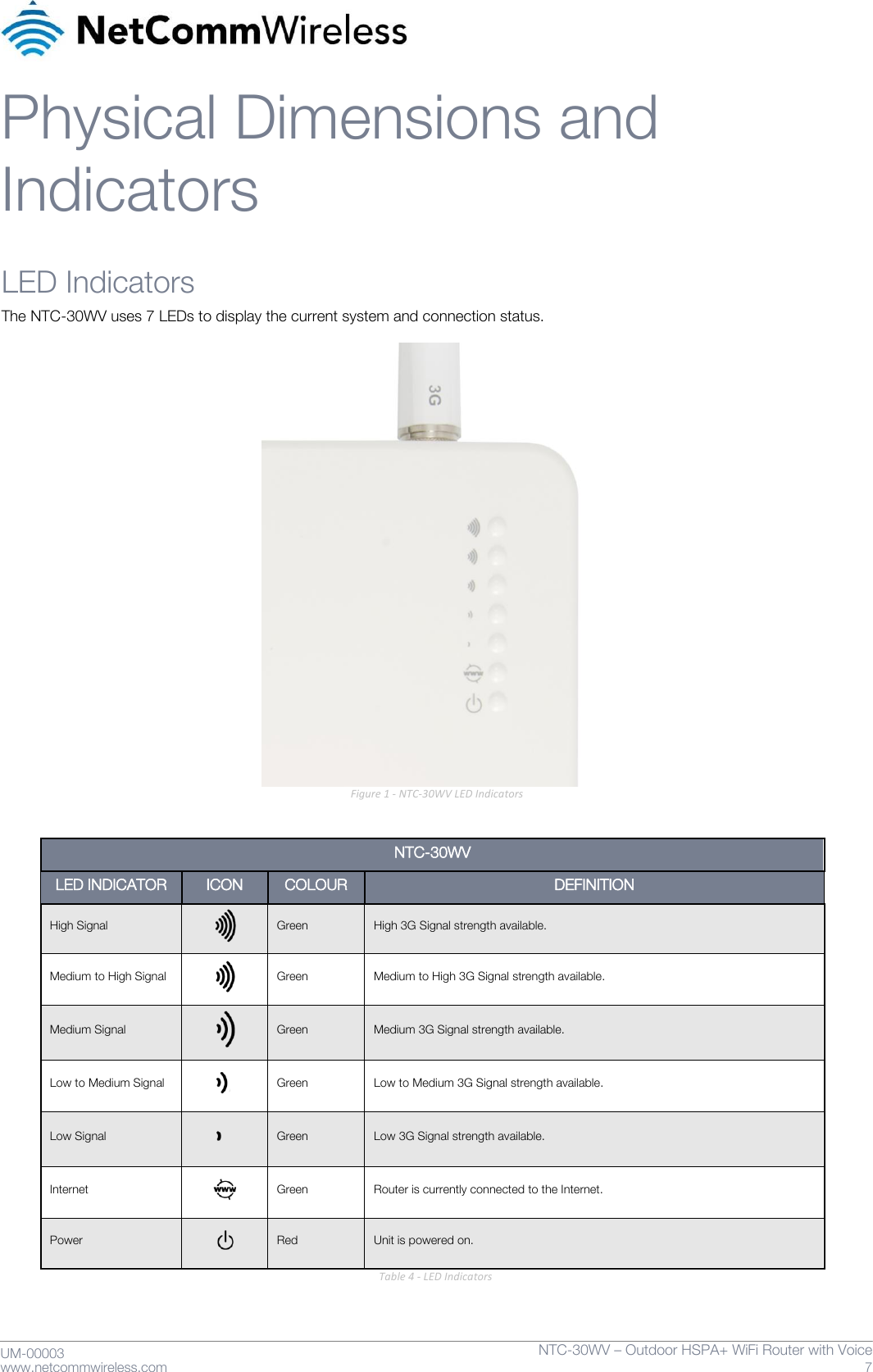
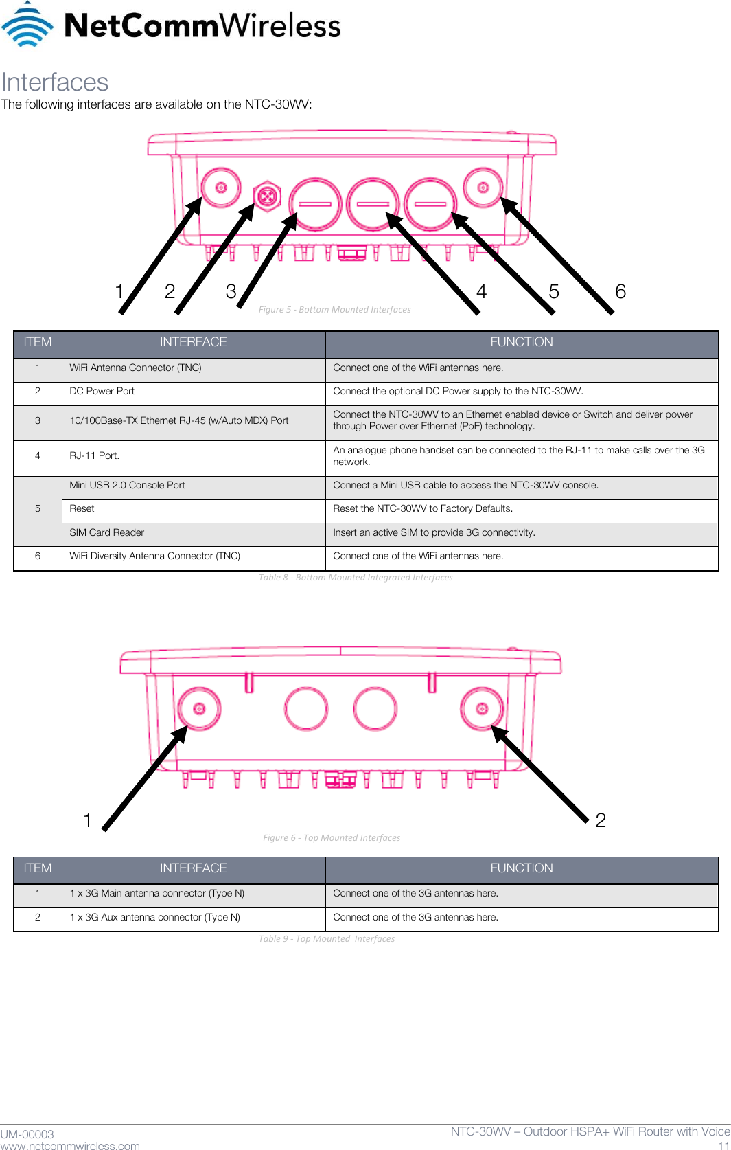
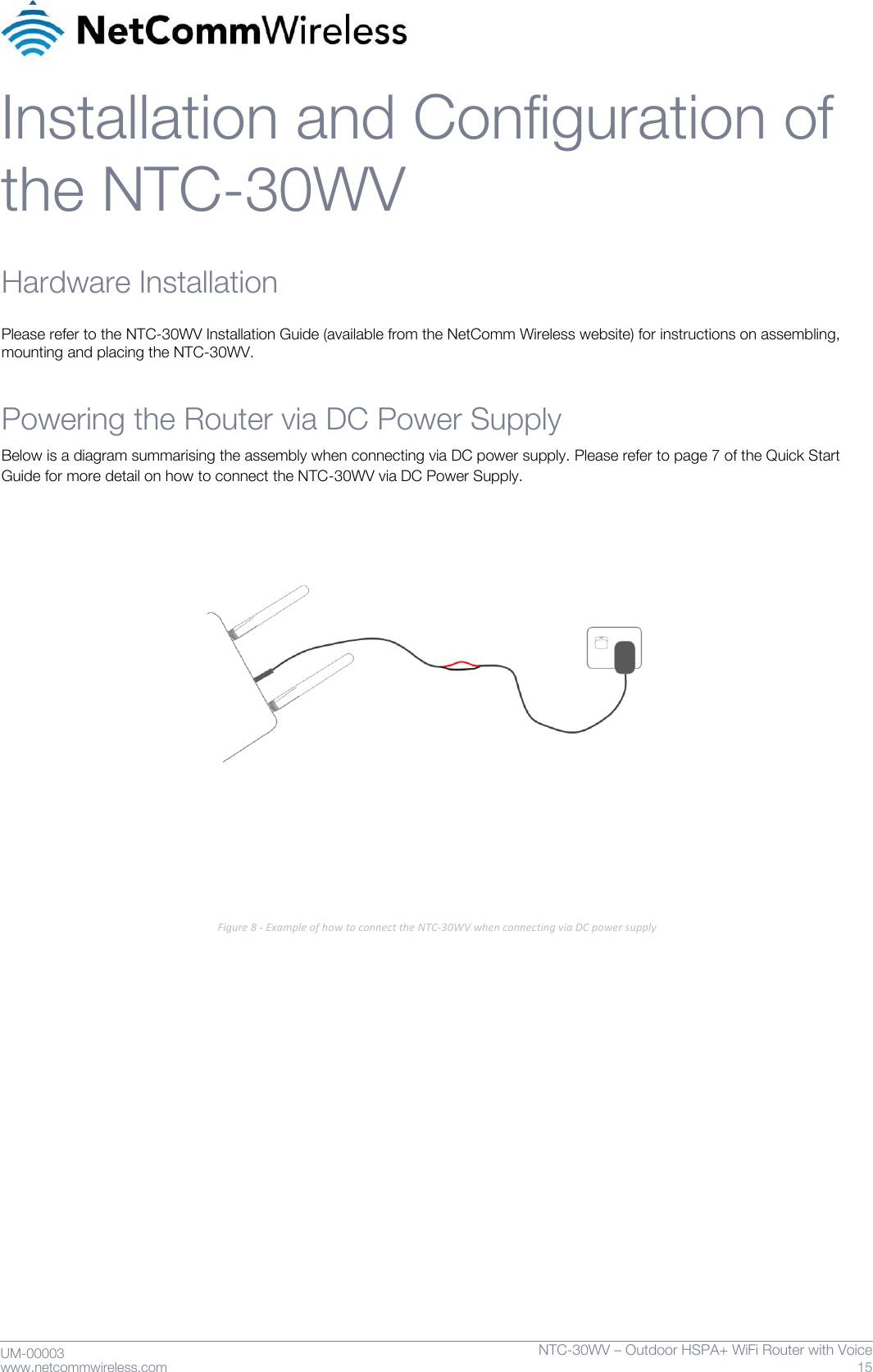
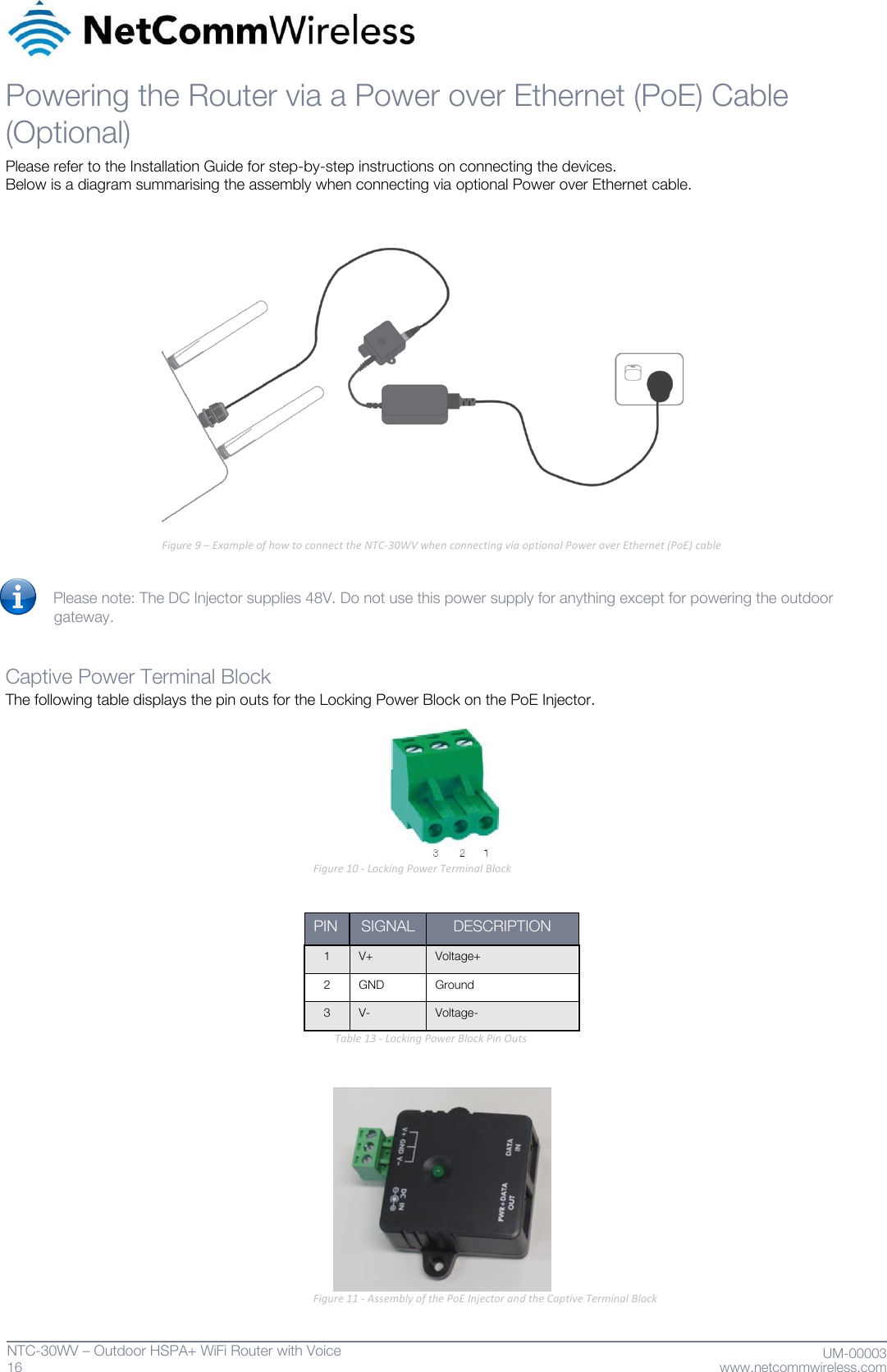

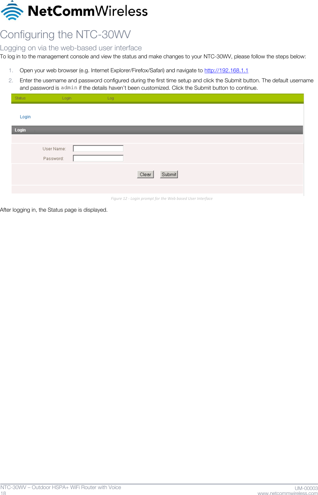
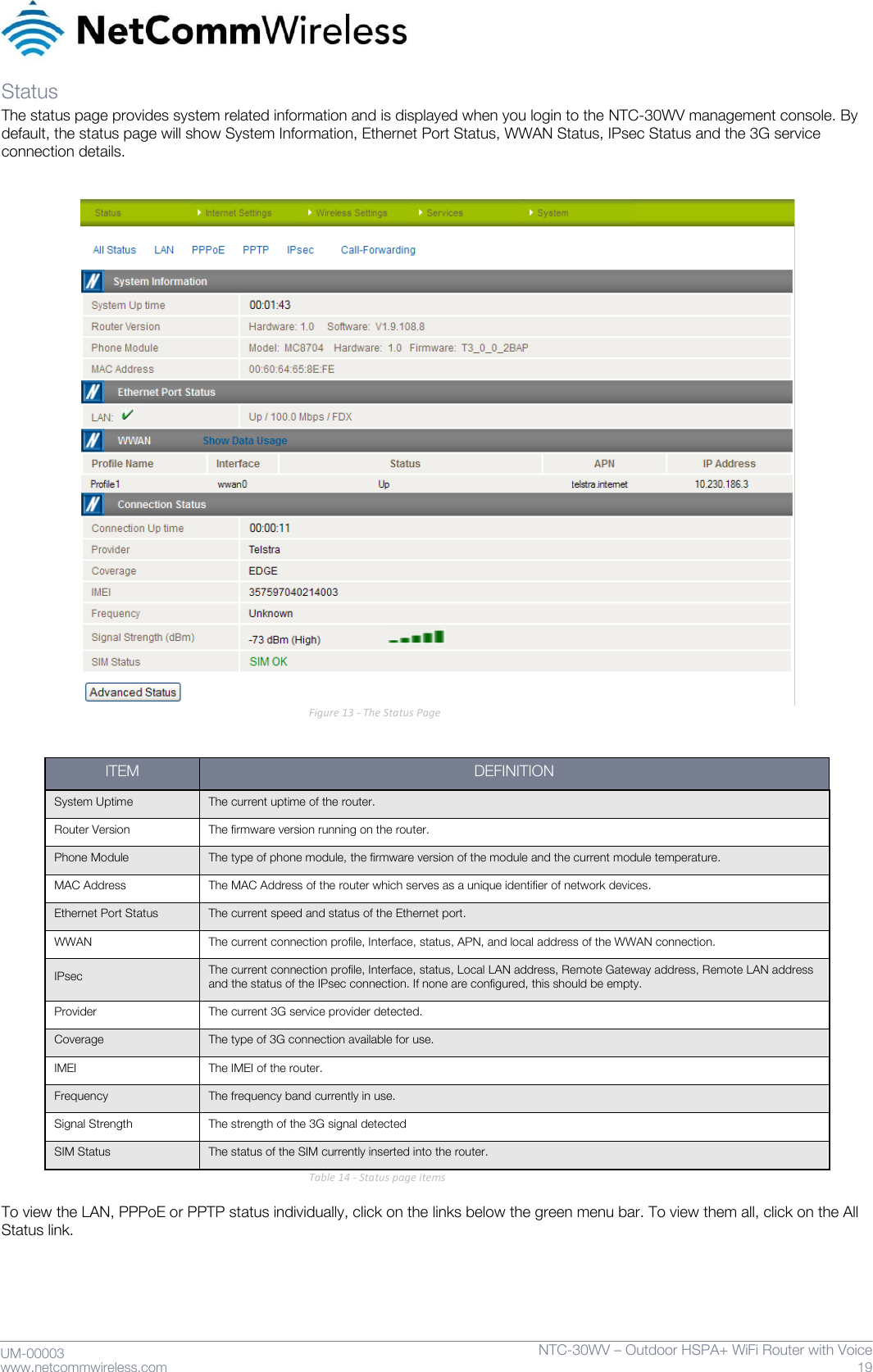
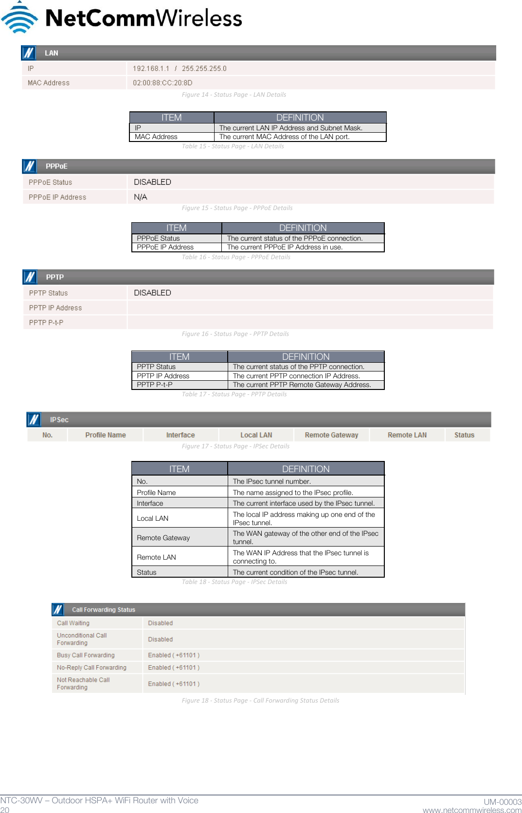
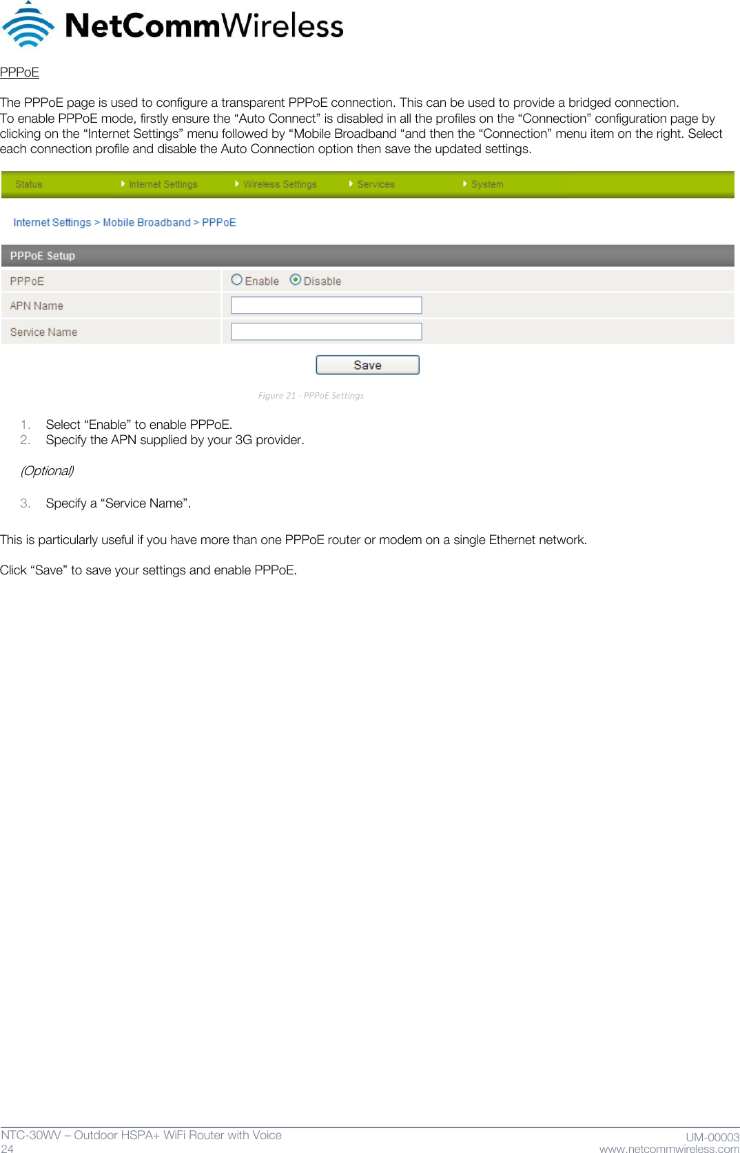
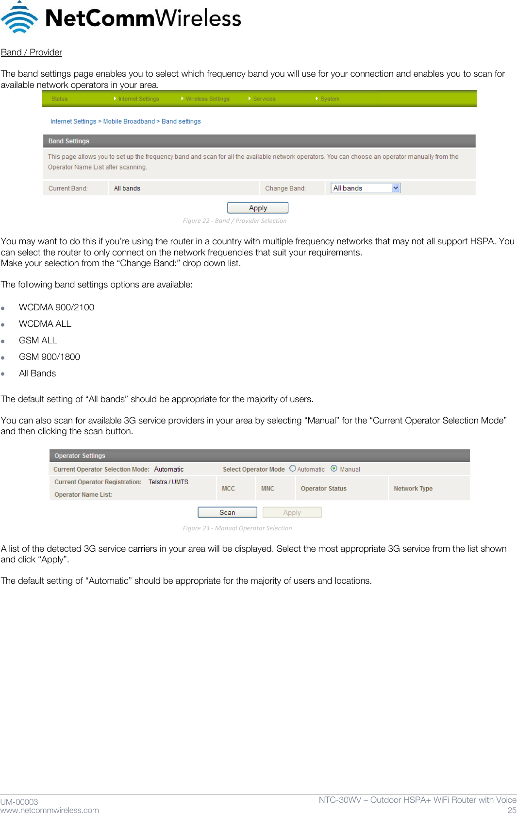
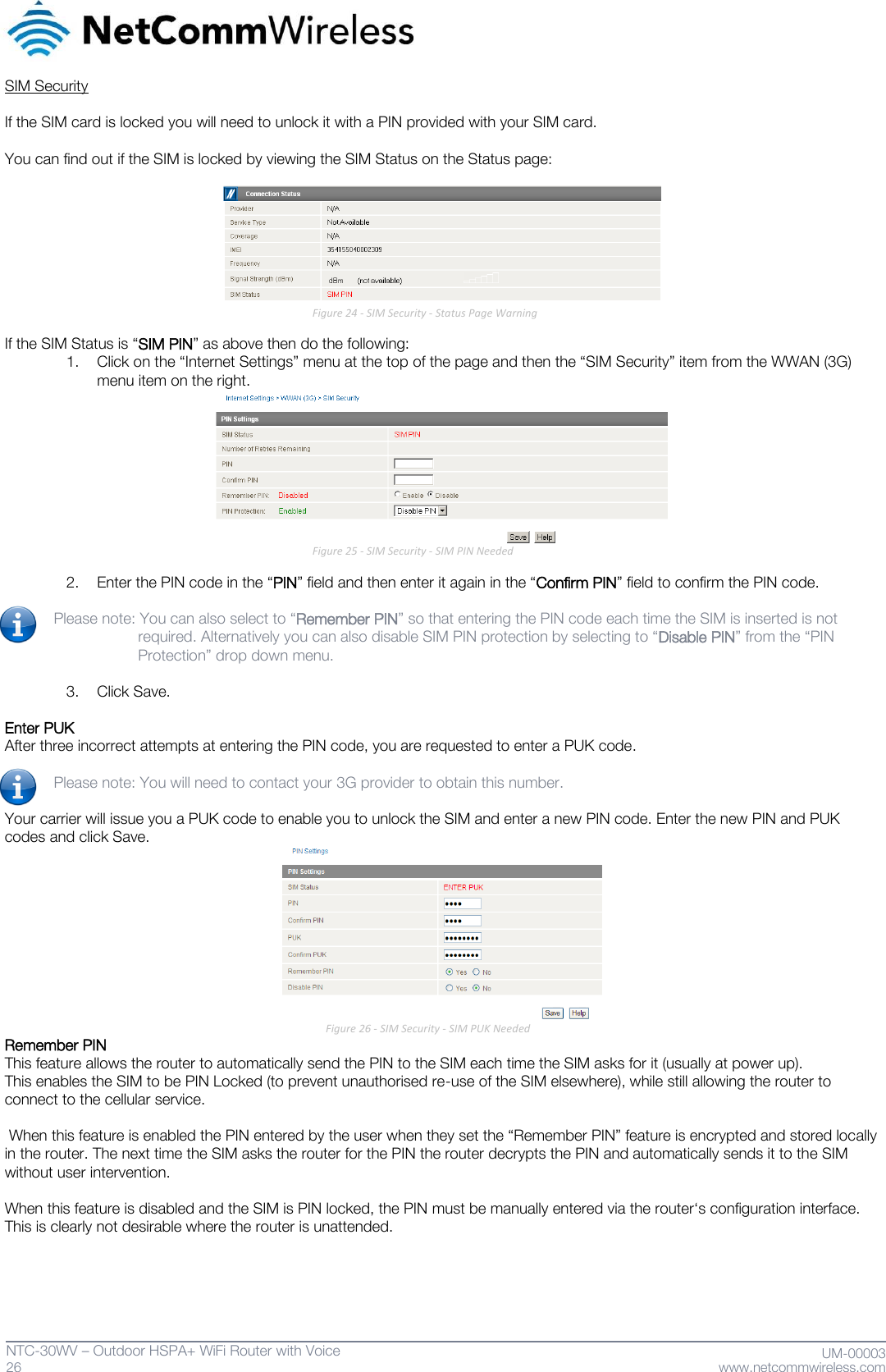
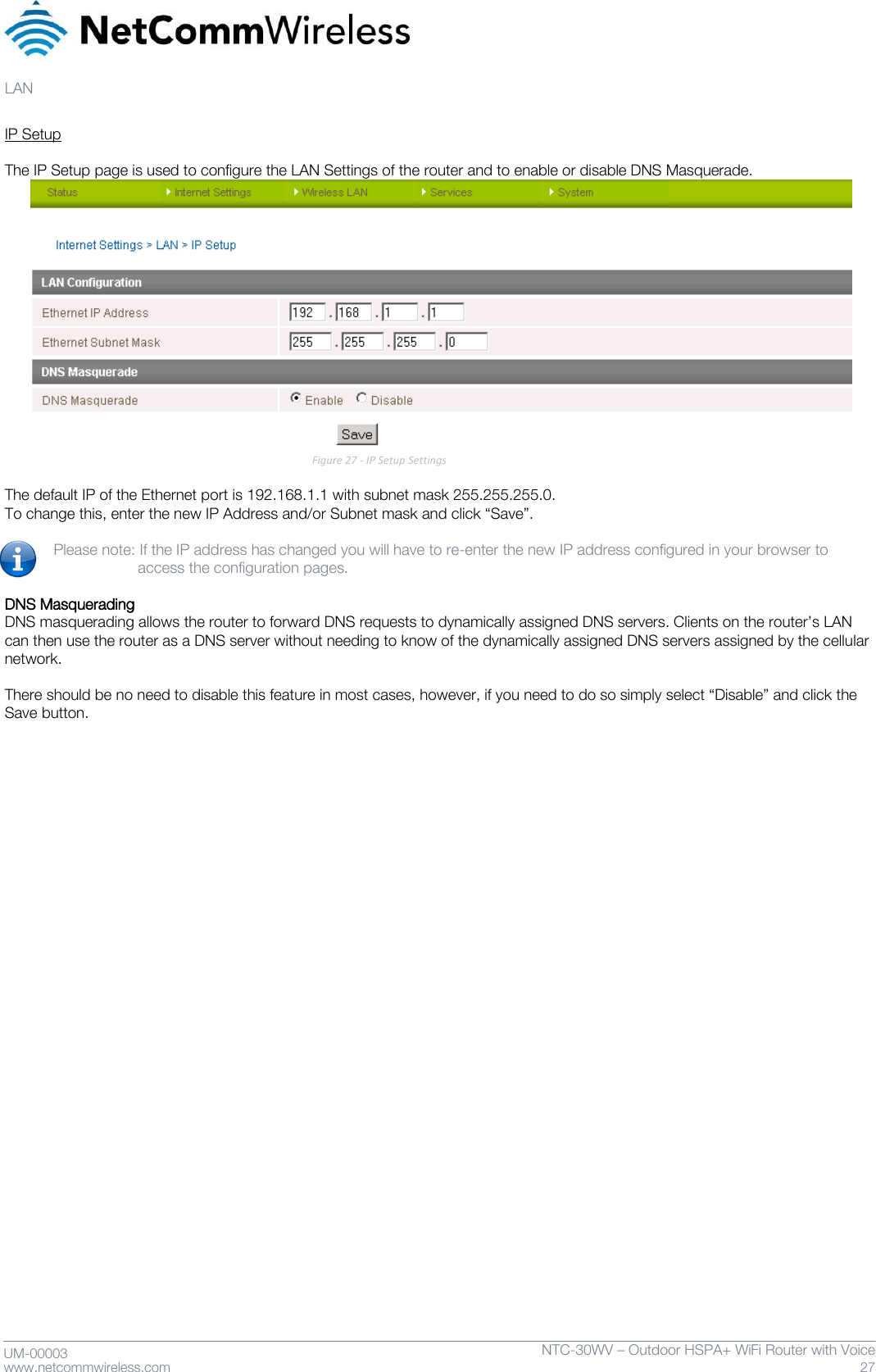
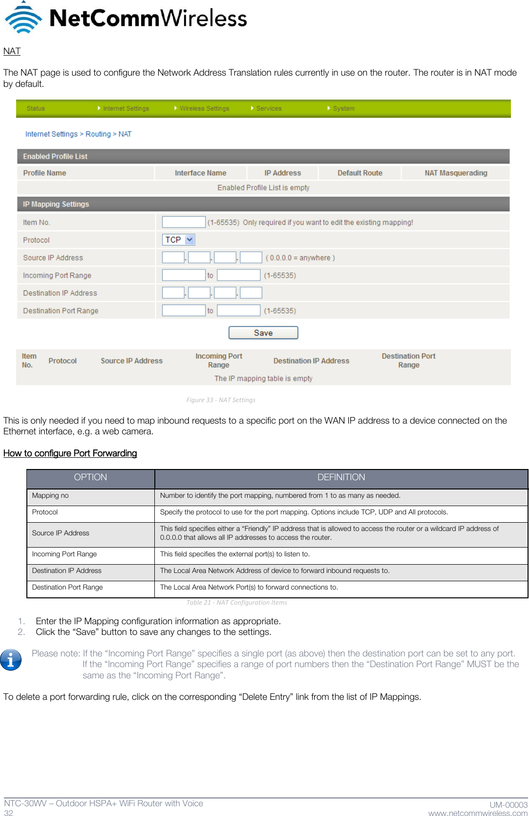
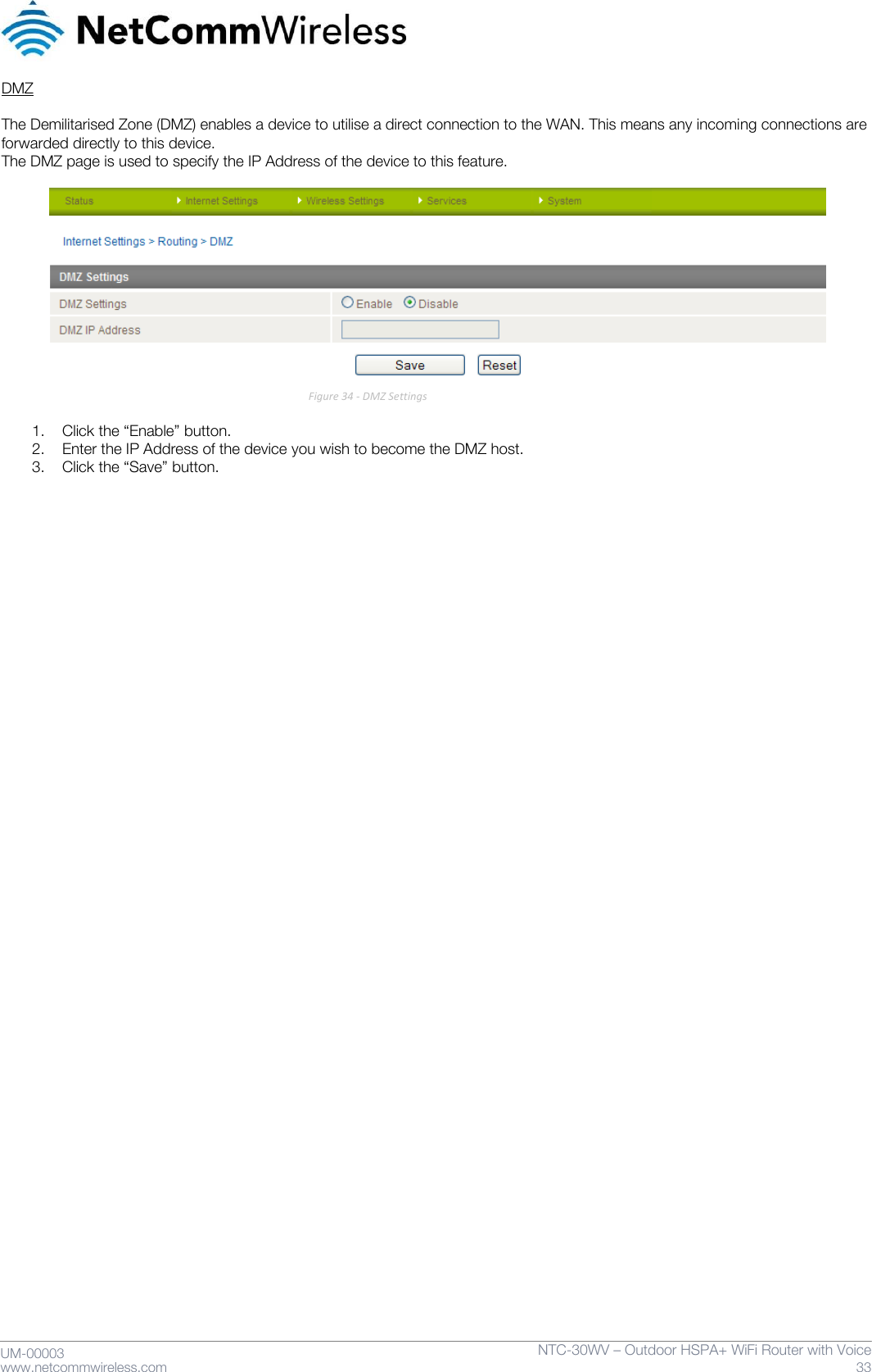
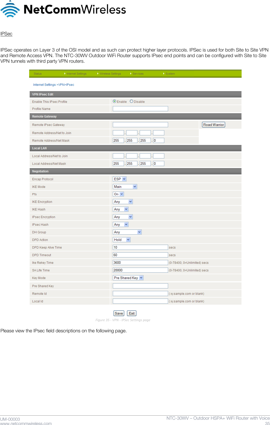
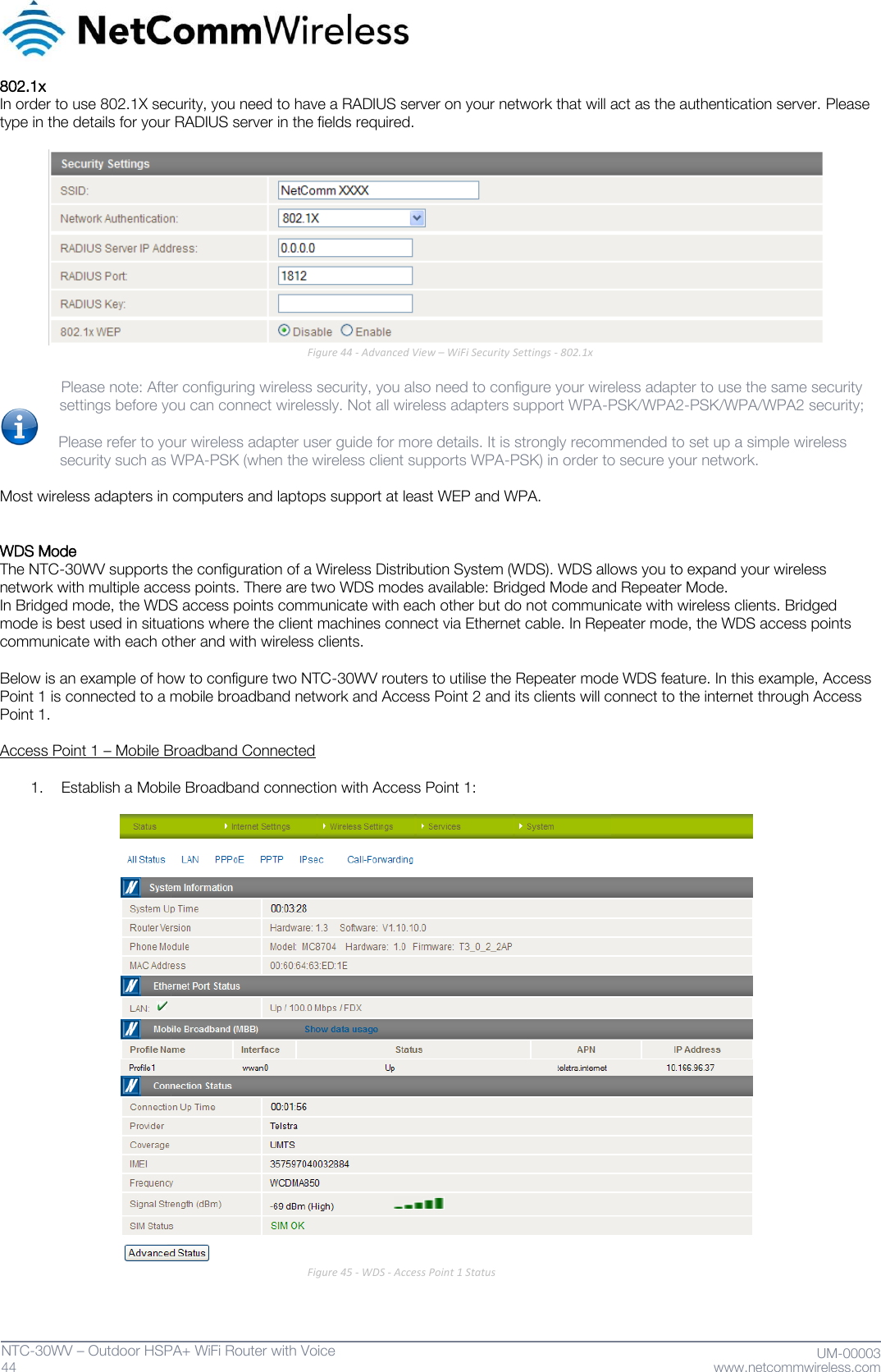
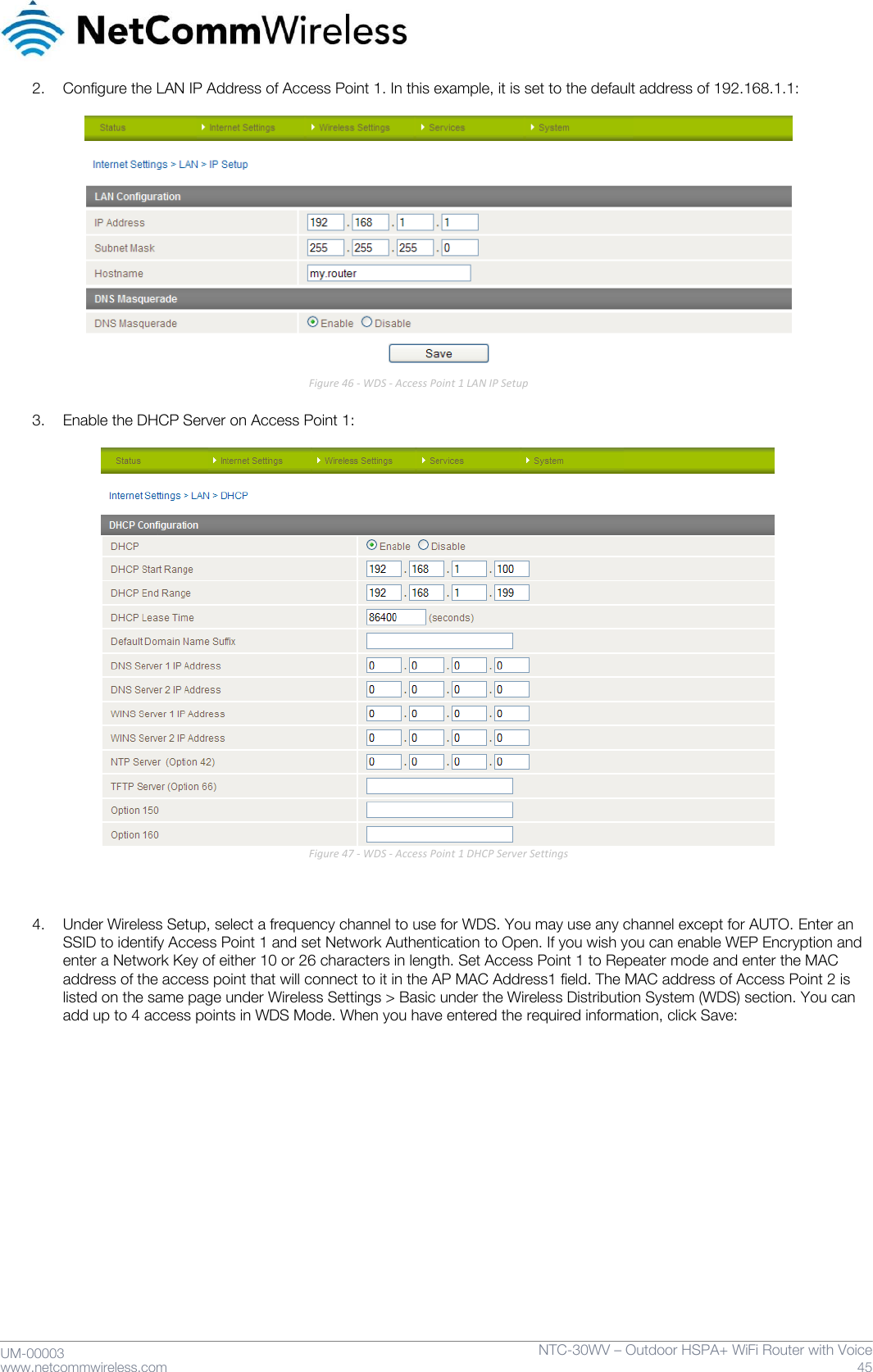
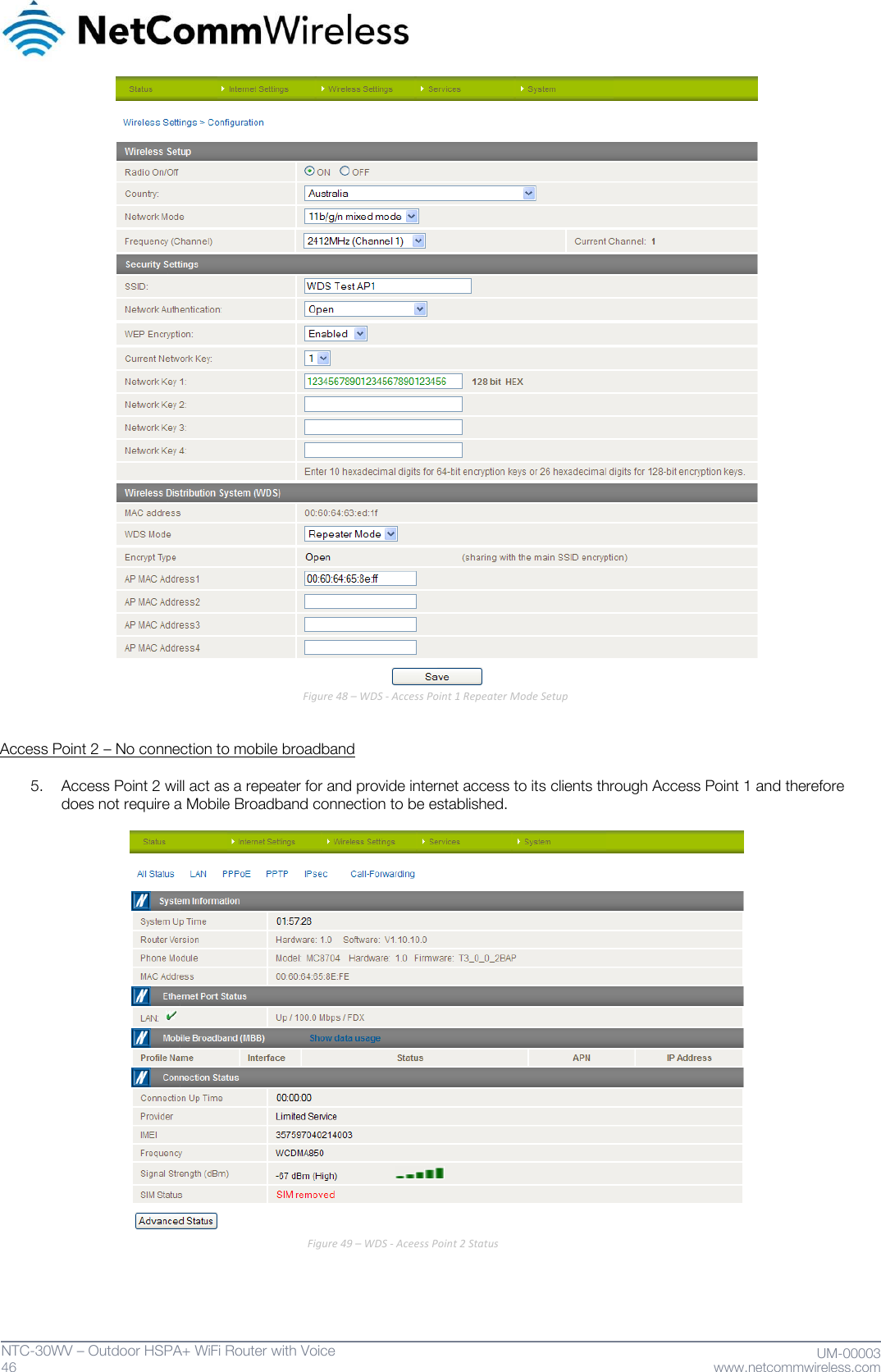
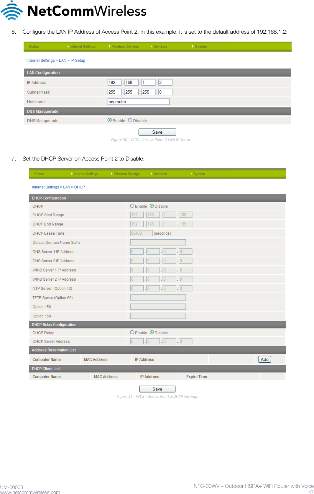
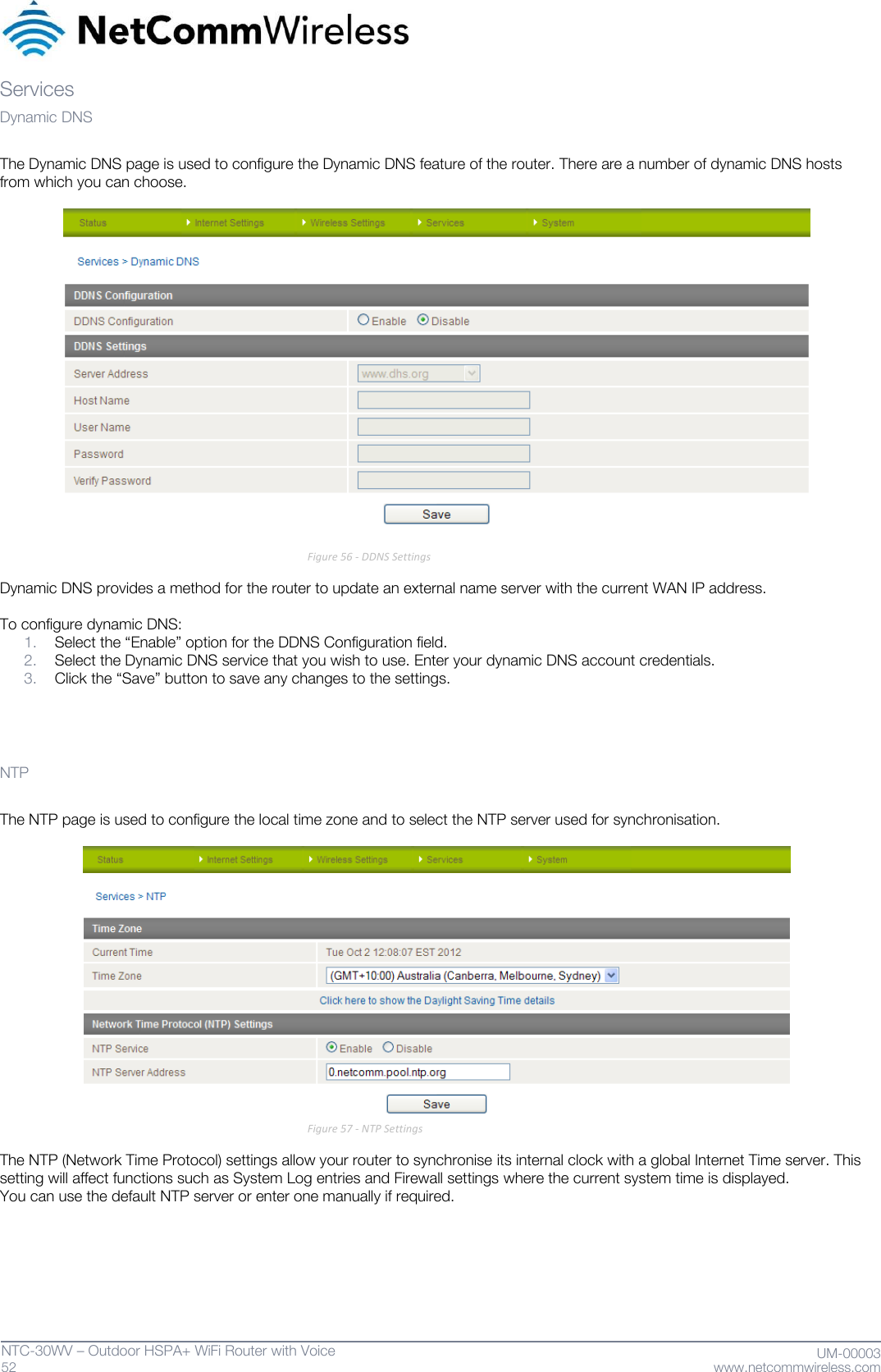
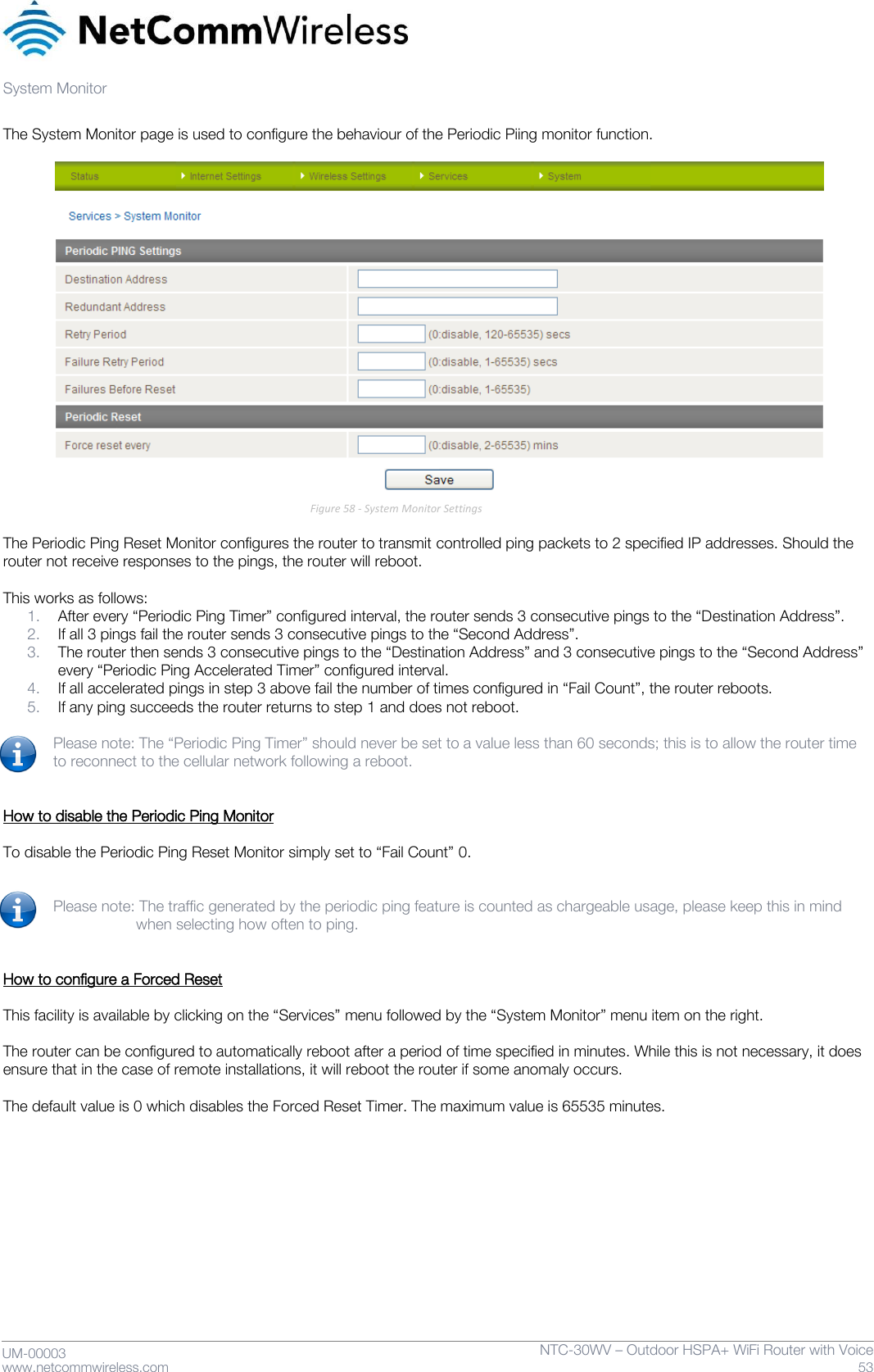
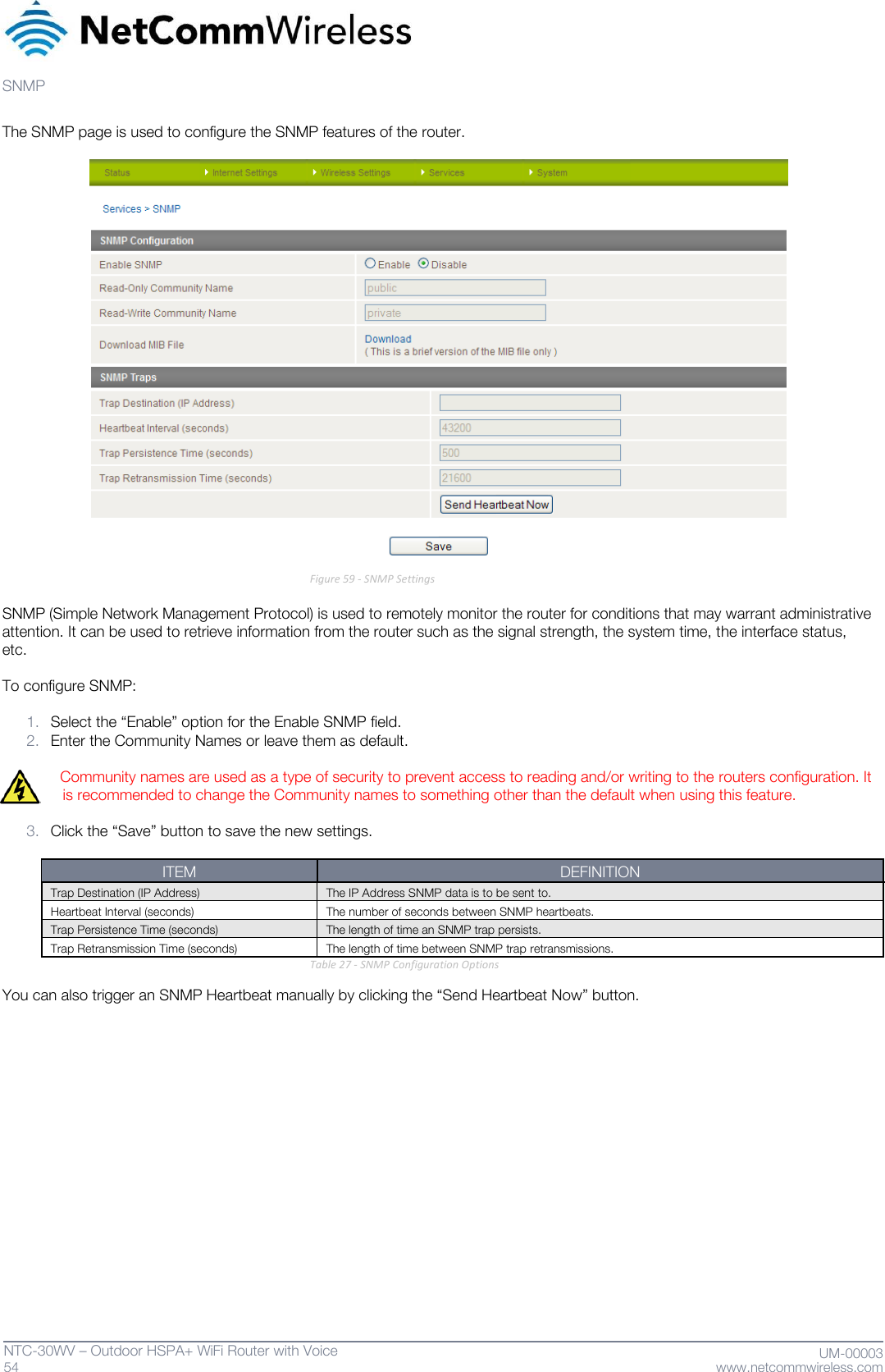
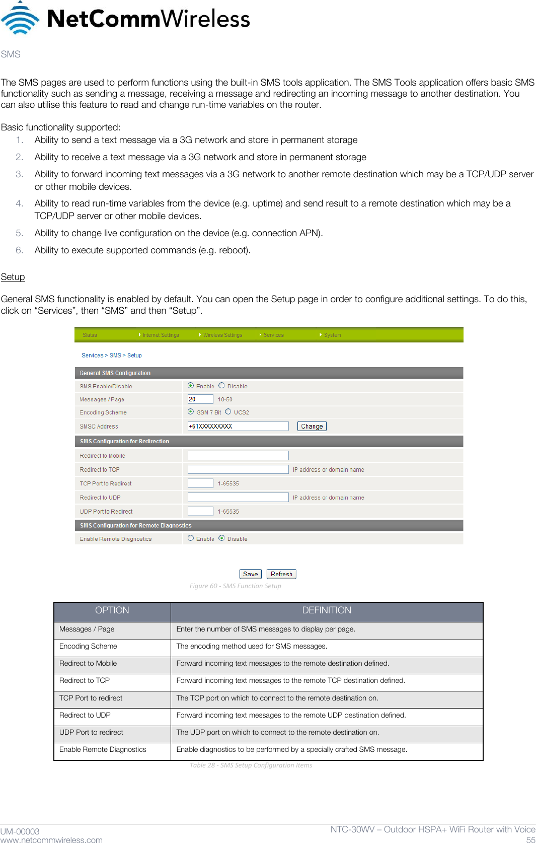
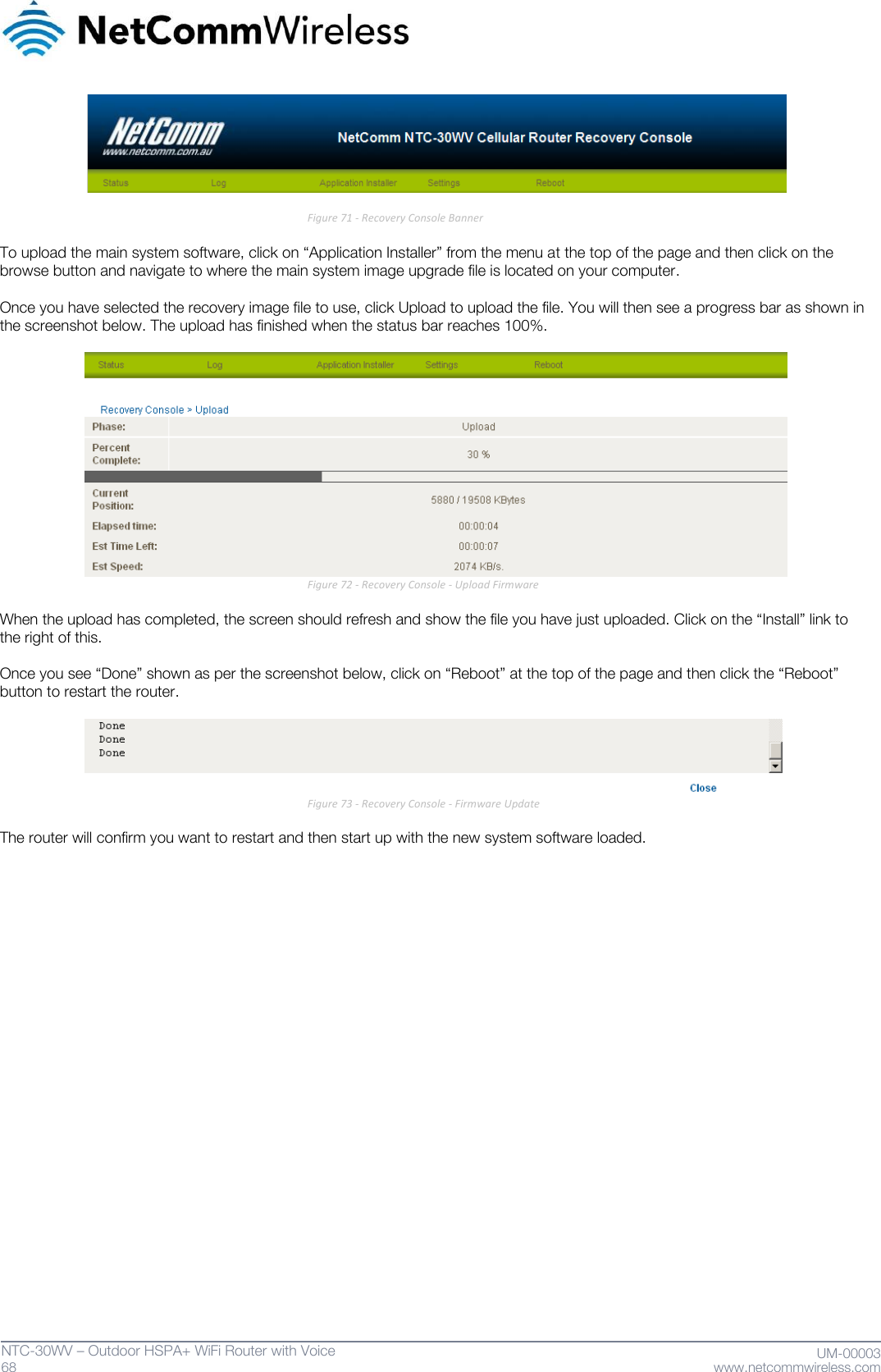
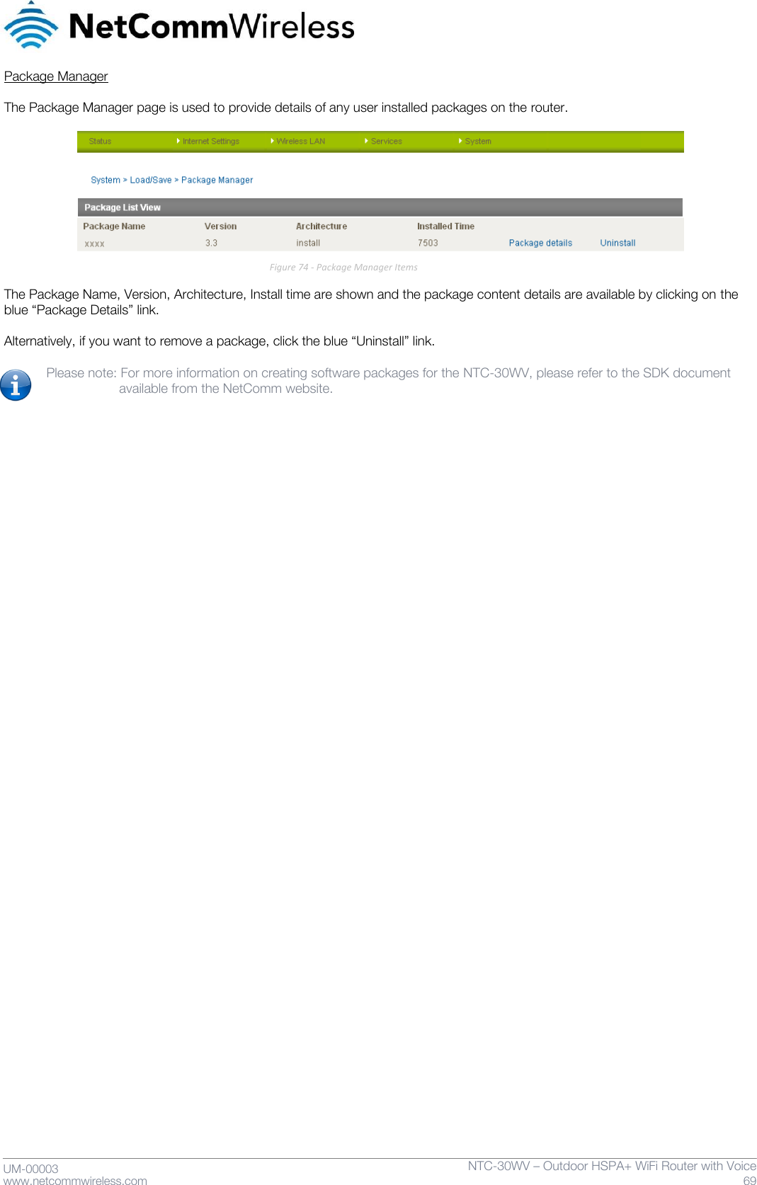
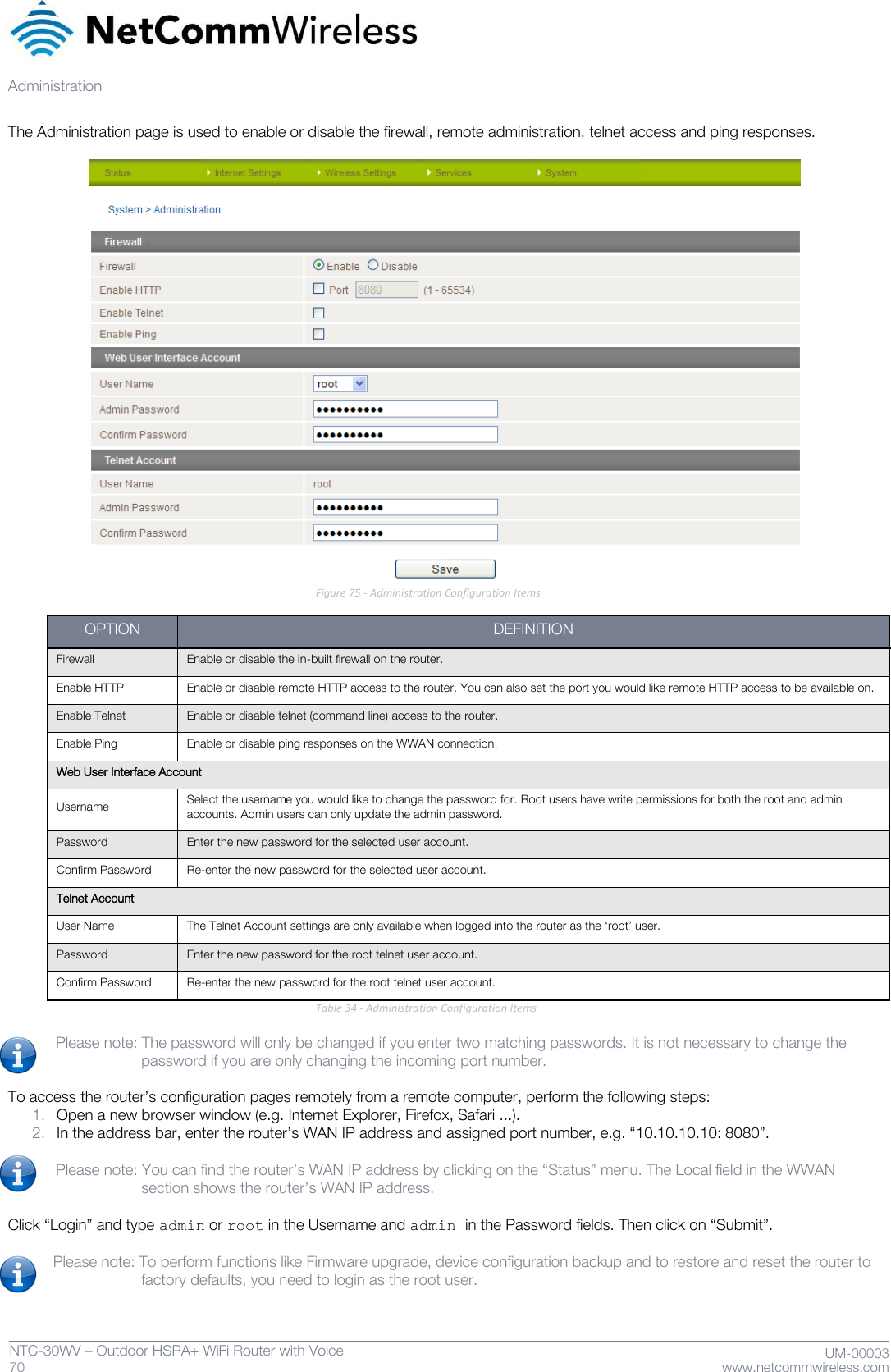
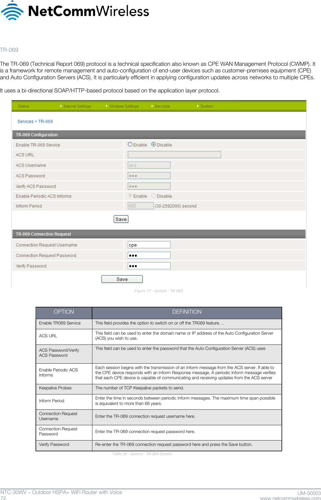
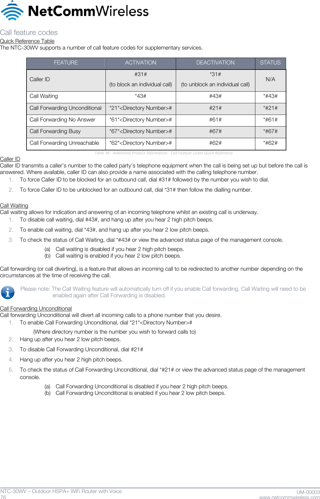
![UM-00003 www.netcommwireless.com NTC-30WV – Outdoor HSPA+ WiFi Router with Voice 71 System Configuration The System configuration page is used to specify an external syslog server and the TCP Keepalive settings. The TCP Keepalive can be used to ensure the WWAN connection does not disconnect due to inactivity. Figure 76 - System Configuration Items OPTION DEFINITION IP / Hostname [:PORT] The IP address and port of the external syslog server you would like logging information sent to. TCP Keepalive Settings Keepalive Enable or Disable the TCP Keepalive function. Keepalive Time The interval between the last packet sent and the first TCP keepalive packet being sent. Keepalive Interval The time between subsequent TCP Keepalive packets. Keepalive Probes The number of TCP Keepalive packets to send. LEDs Power Save Settings LEDs Timeout The length of time before the LEDs on the outside of the router turn off to save power. LEDs Power Save Status The status of the LED power saving function. Table 35 - System Configuration Items](https://usermanual.wiki/NetComm-Wireless/NTC30WV/User-Guide-1820601-Page-71.png)