NetComm Wireless NTC40WV Access Point User Manual
NetComm Wireless Limited Access Point
UserManual.wiki
>
NetComm Wireless
>
NTC40WV User Manual
user manual
Navigation menu
Upload a User Manual
Namespaces
Wiki Guide
HTML
PDF
Info
Views
User Manual
Discussion / Help
Navigation


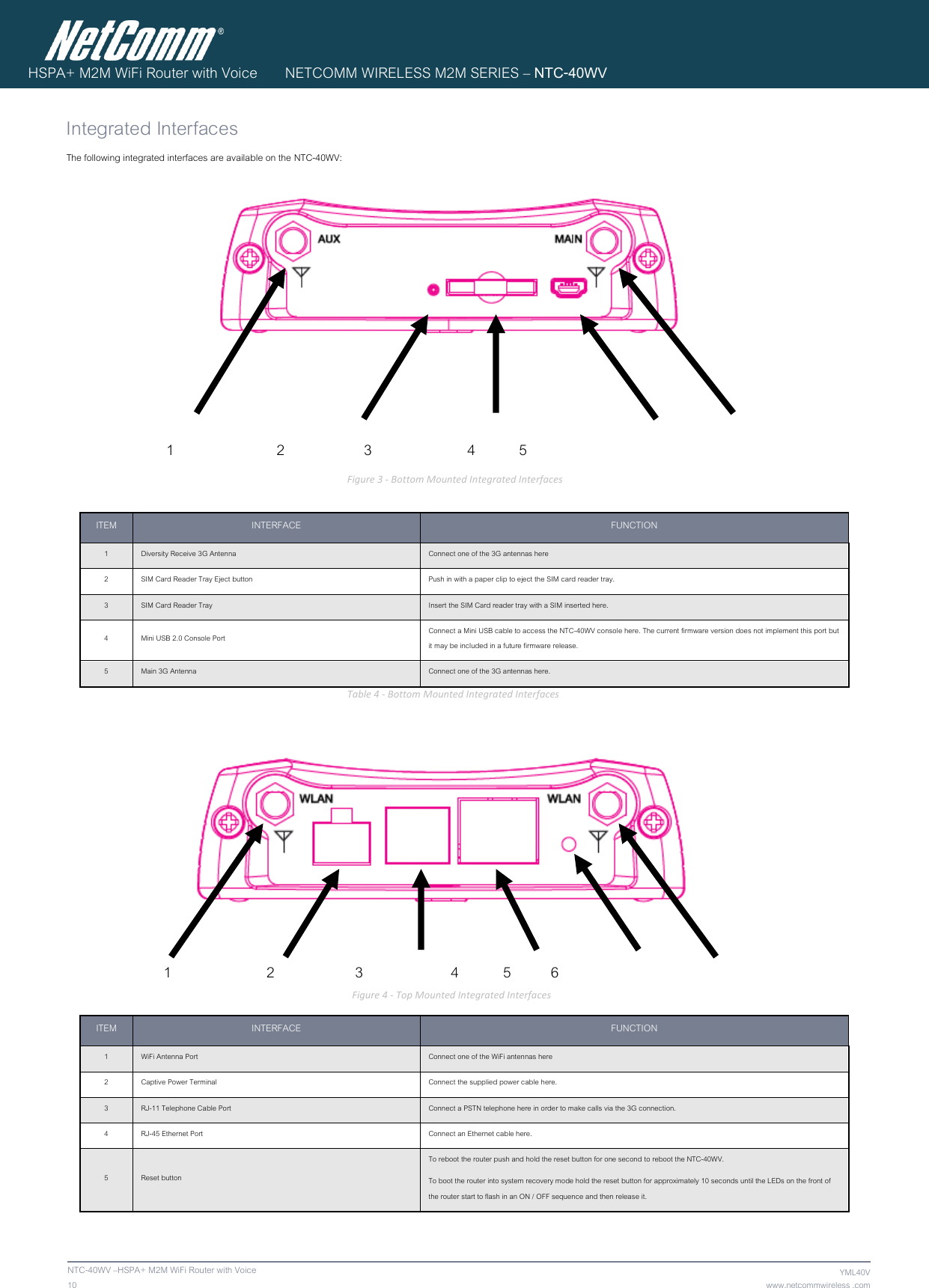
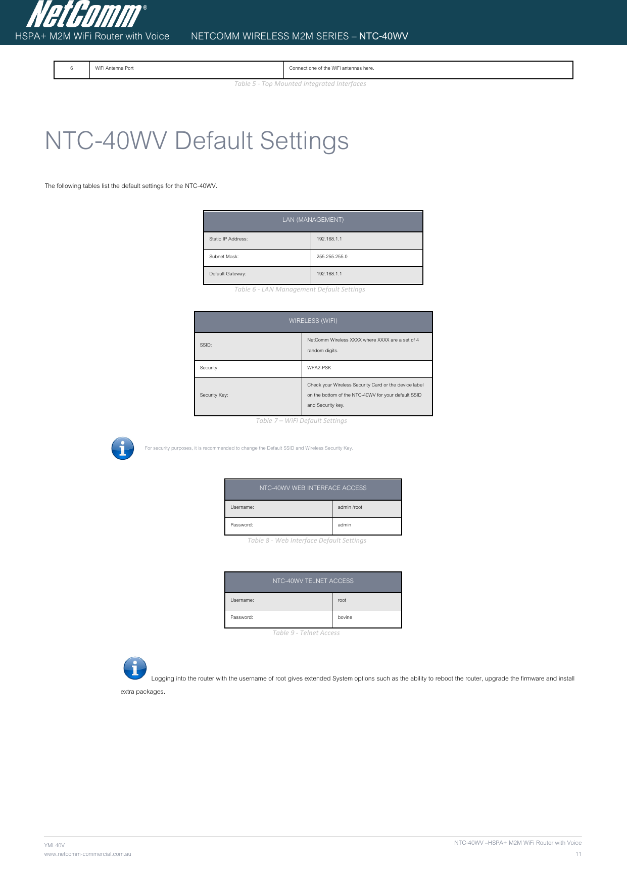
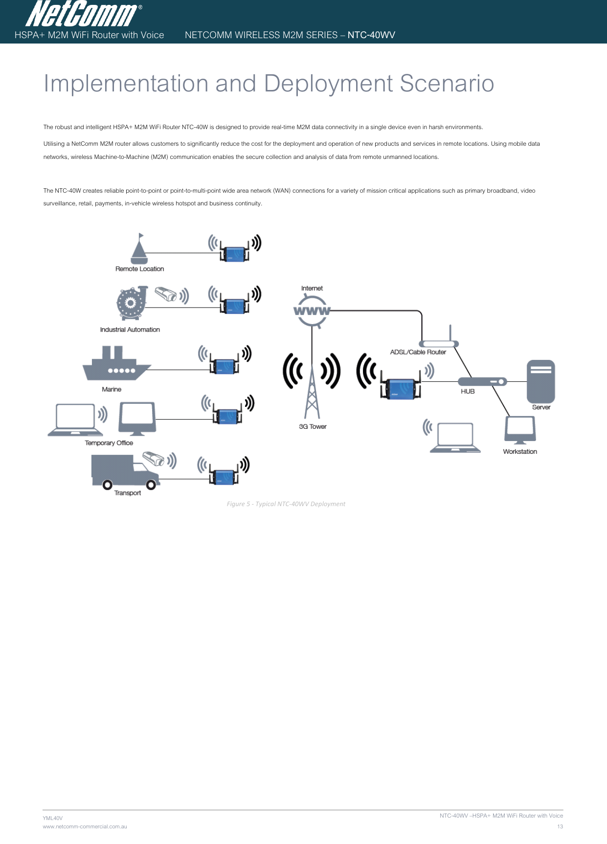
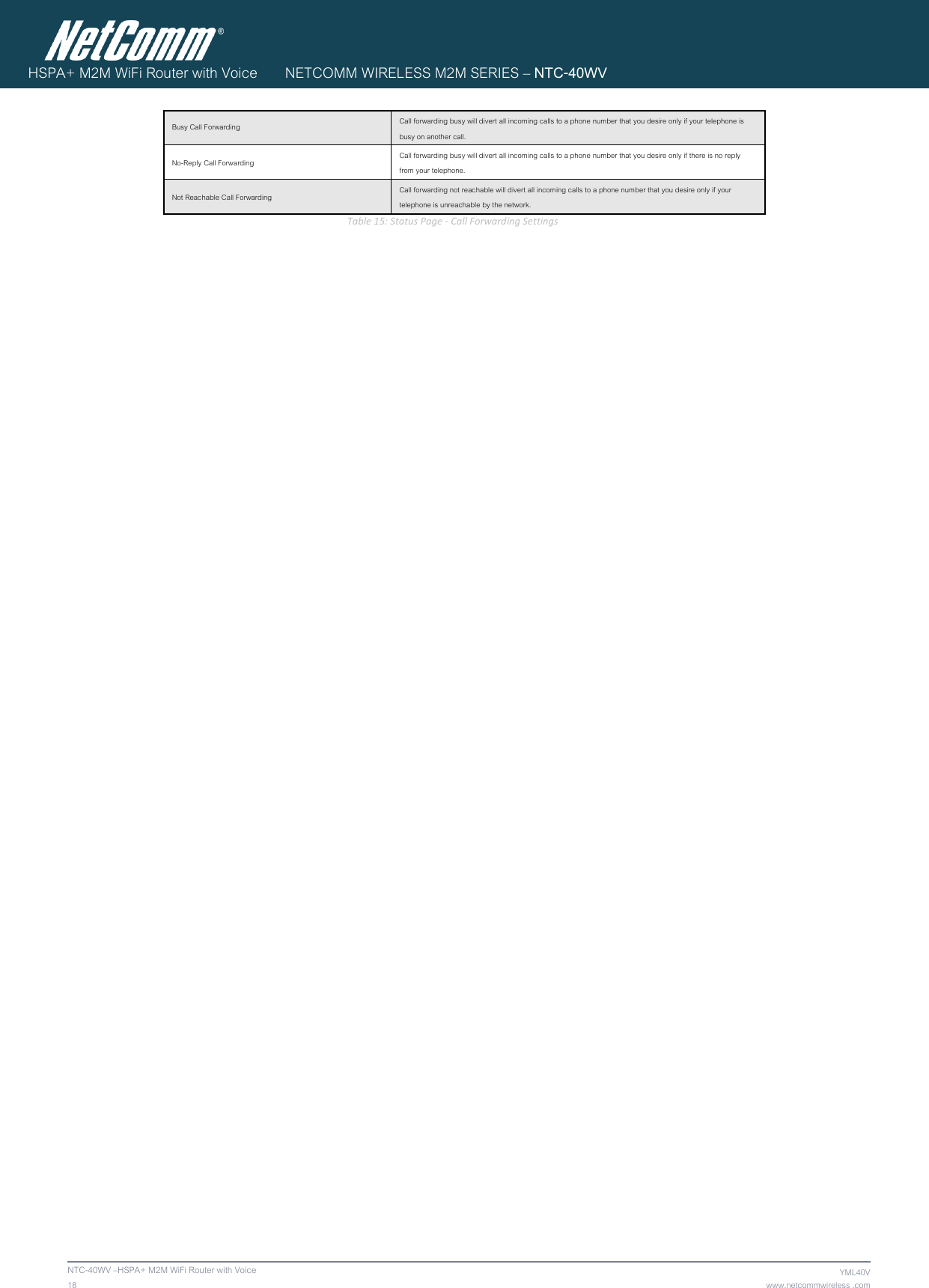

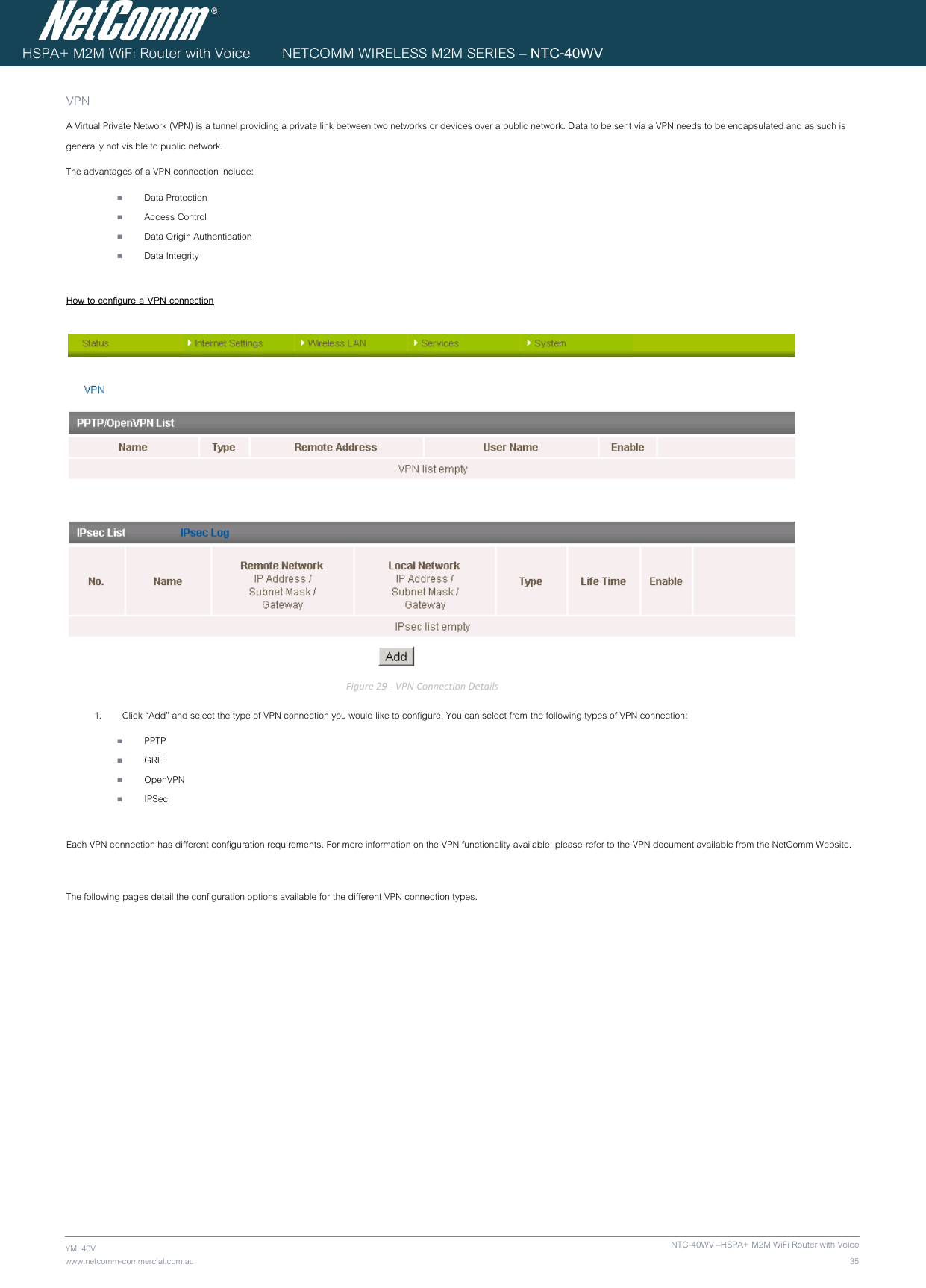
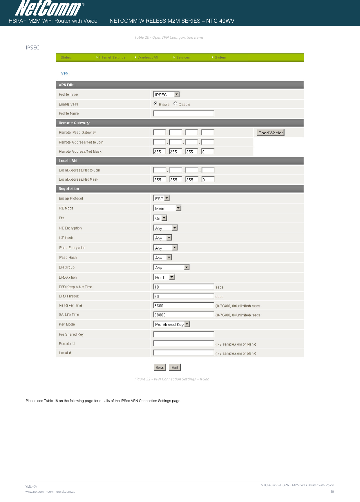

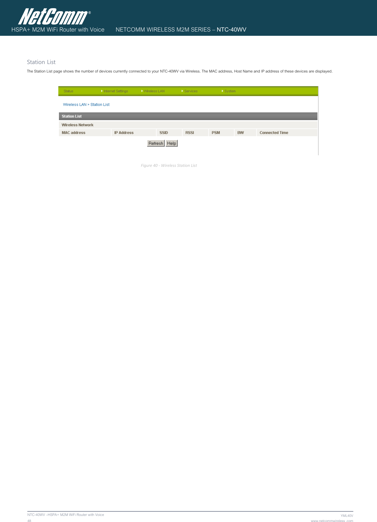
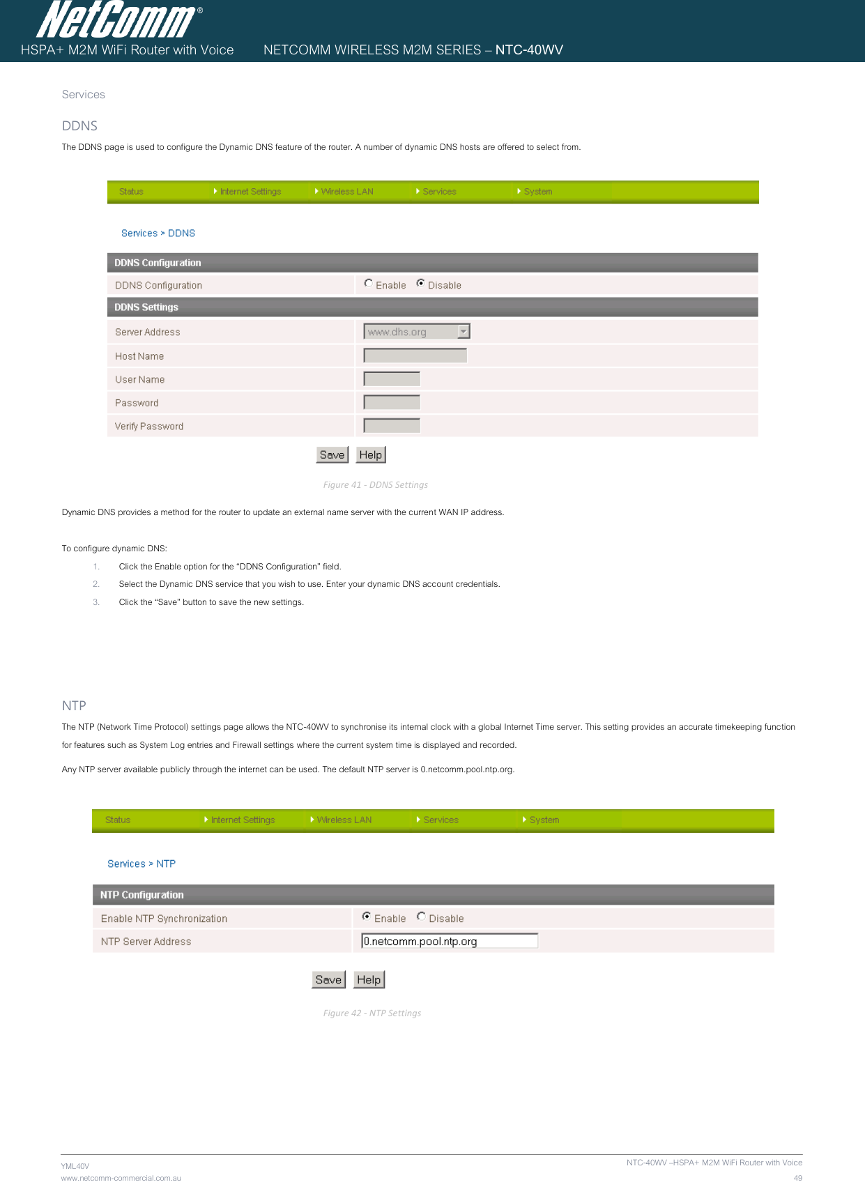
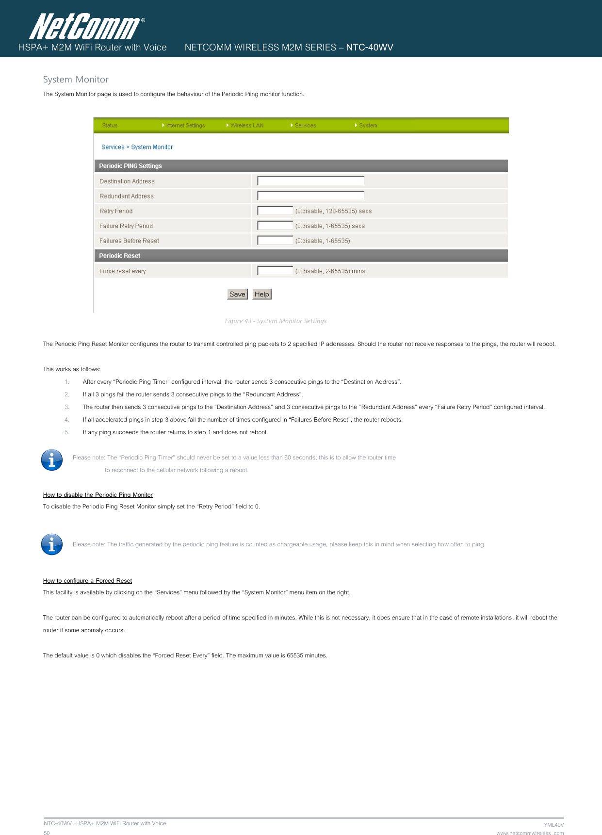
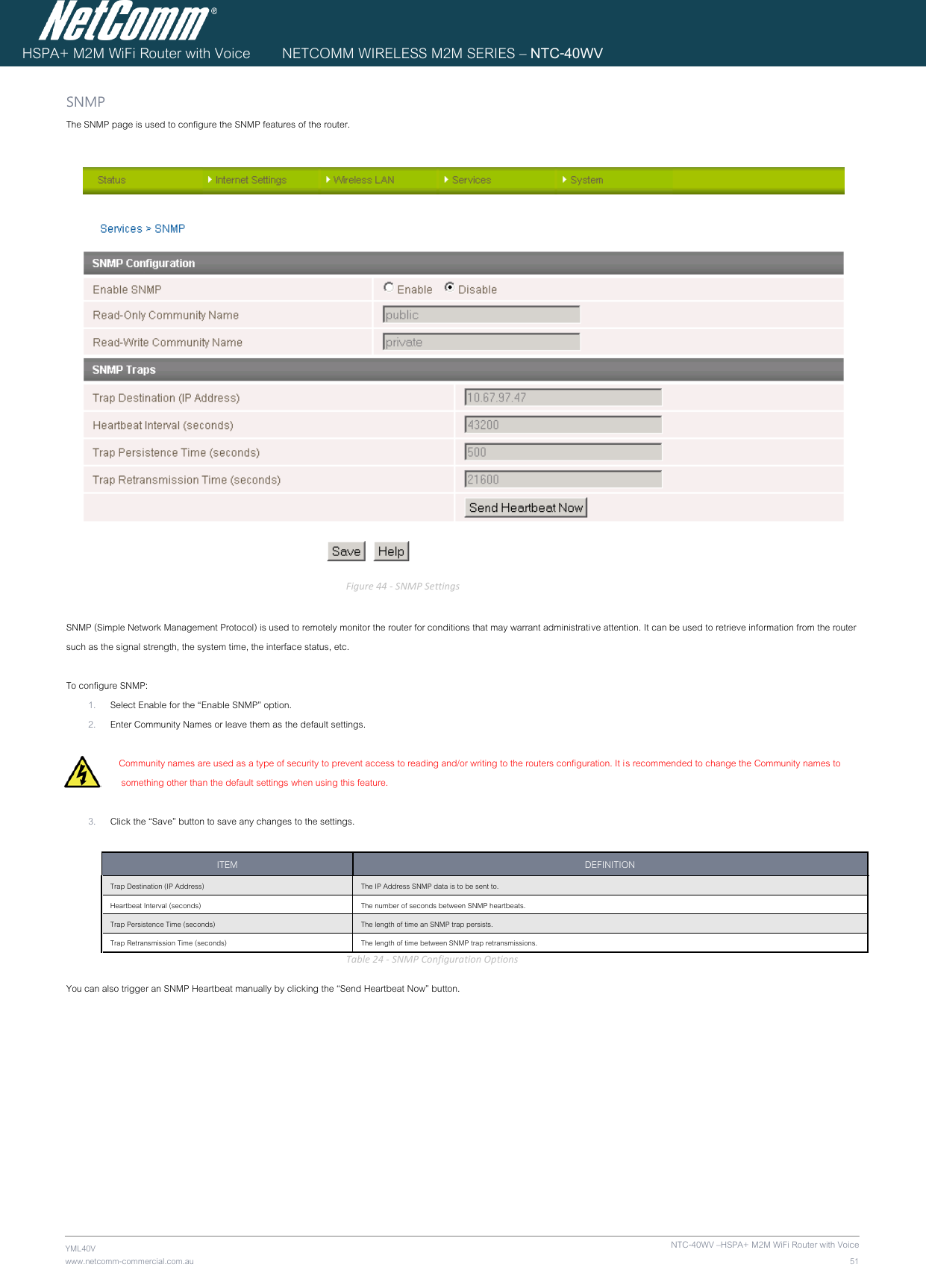
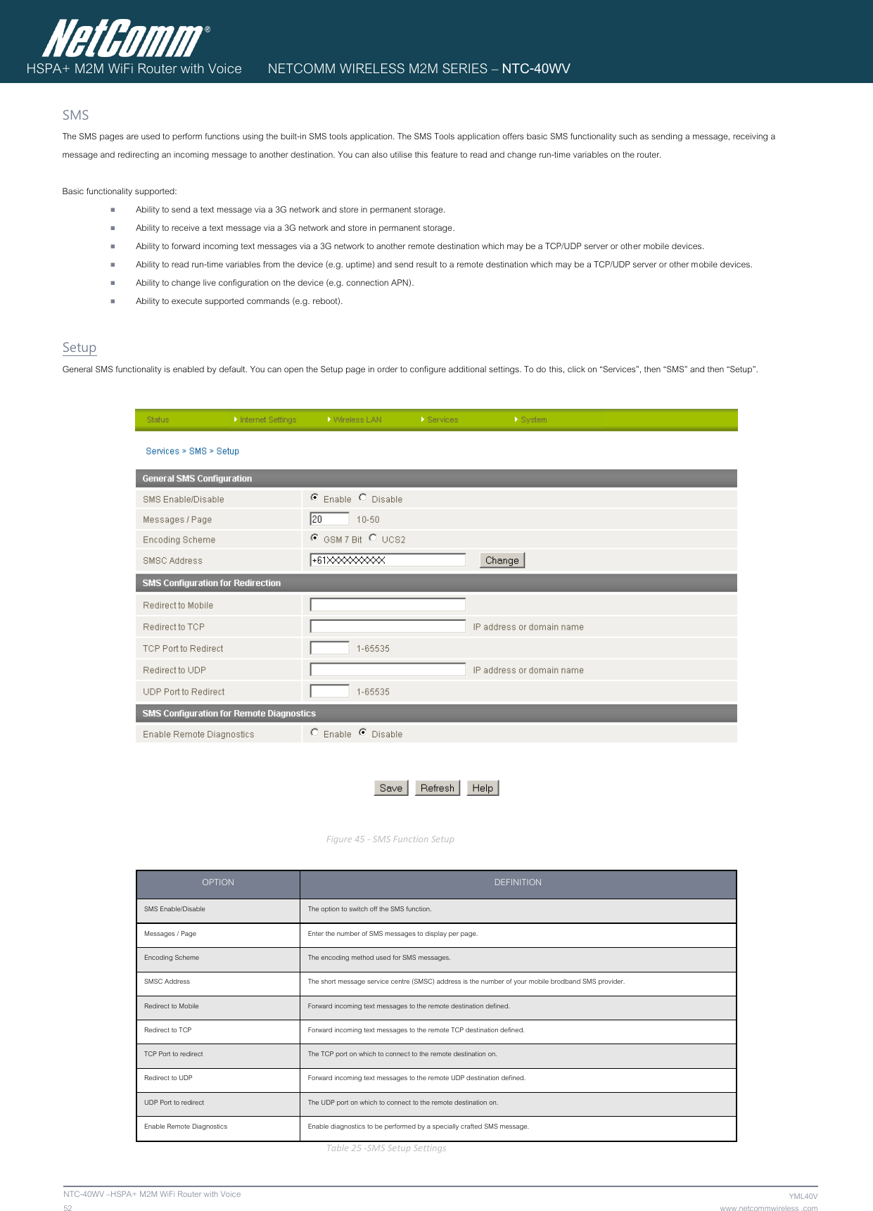


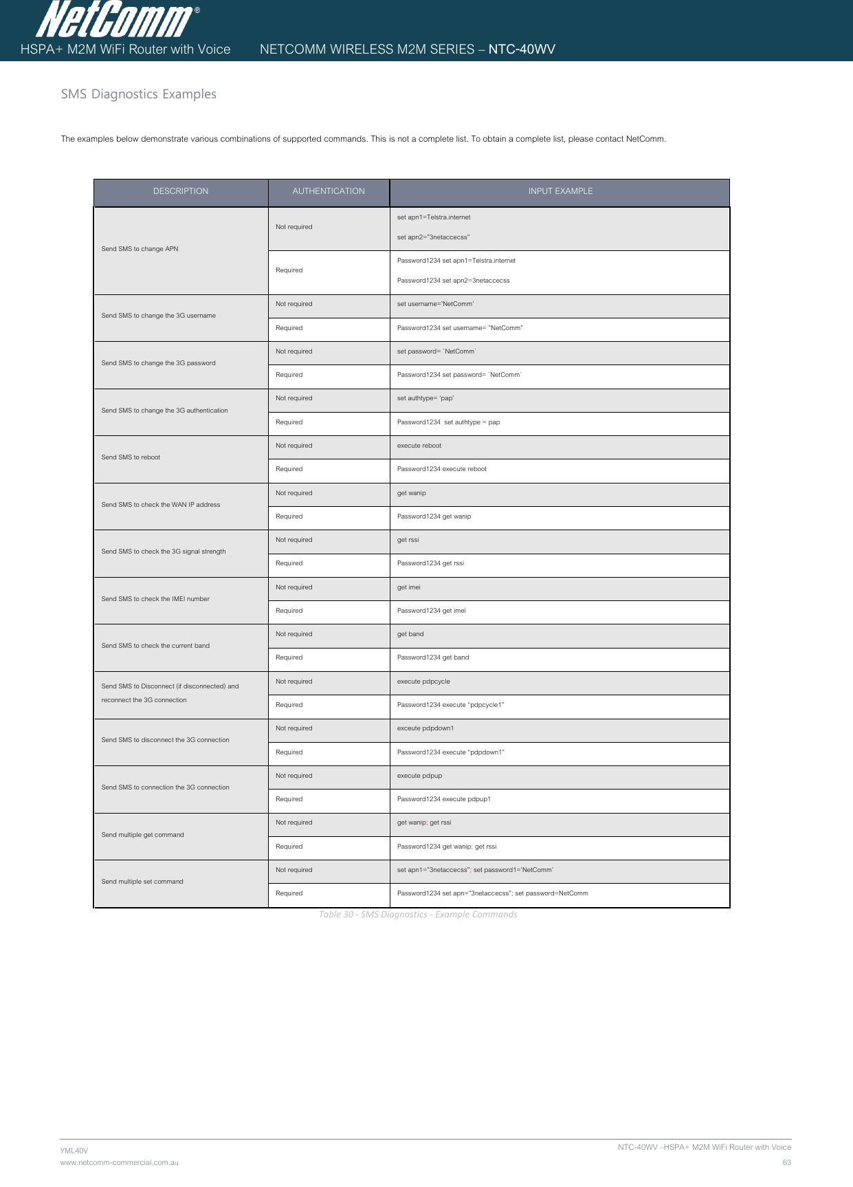
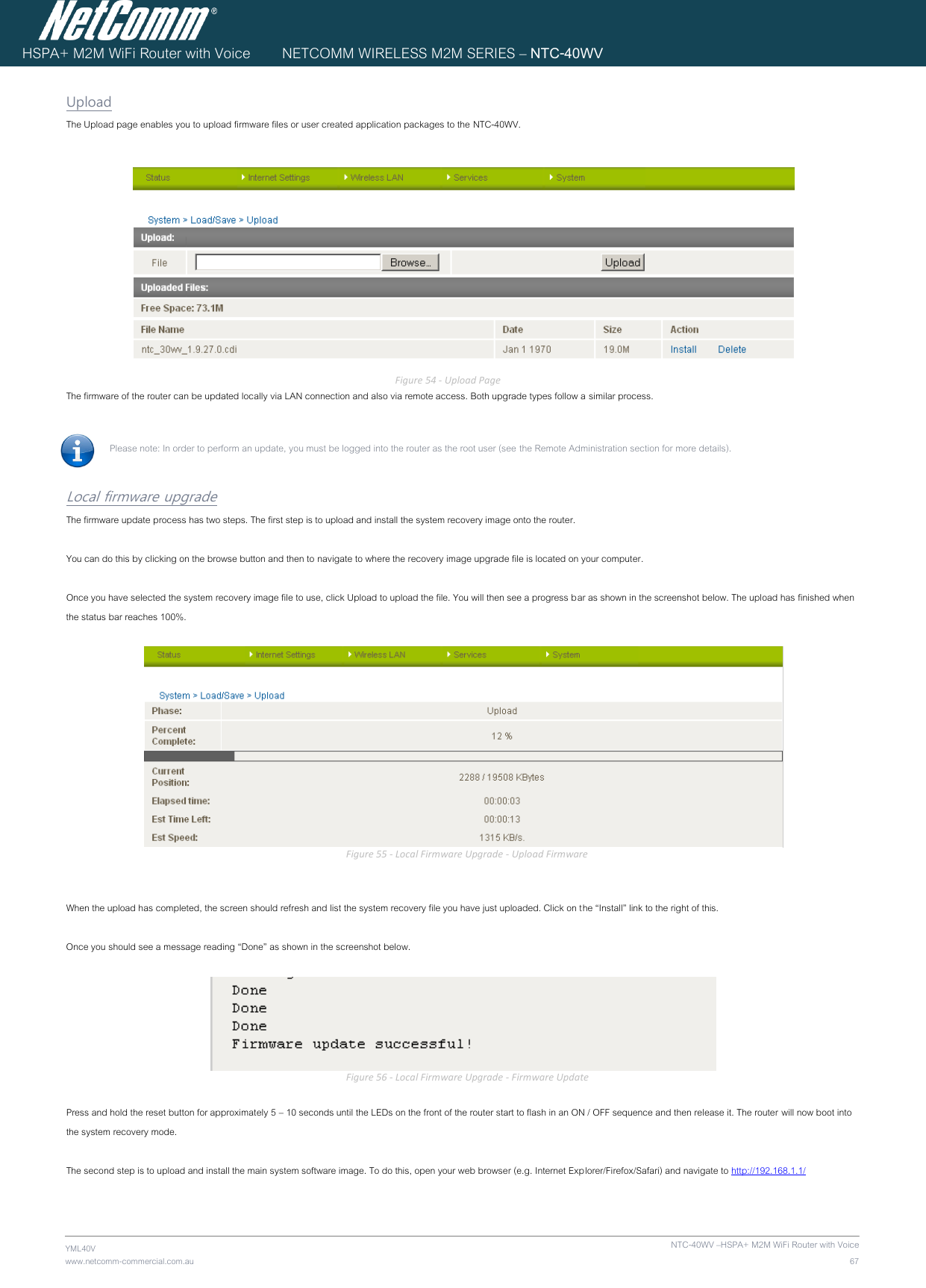
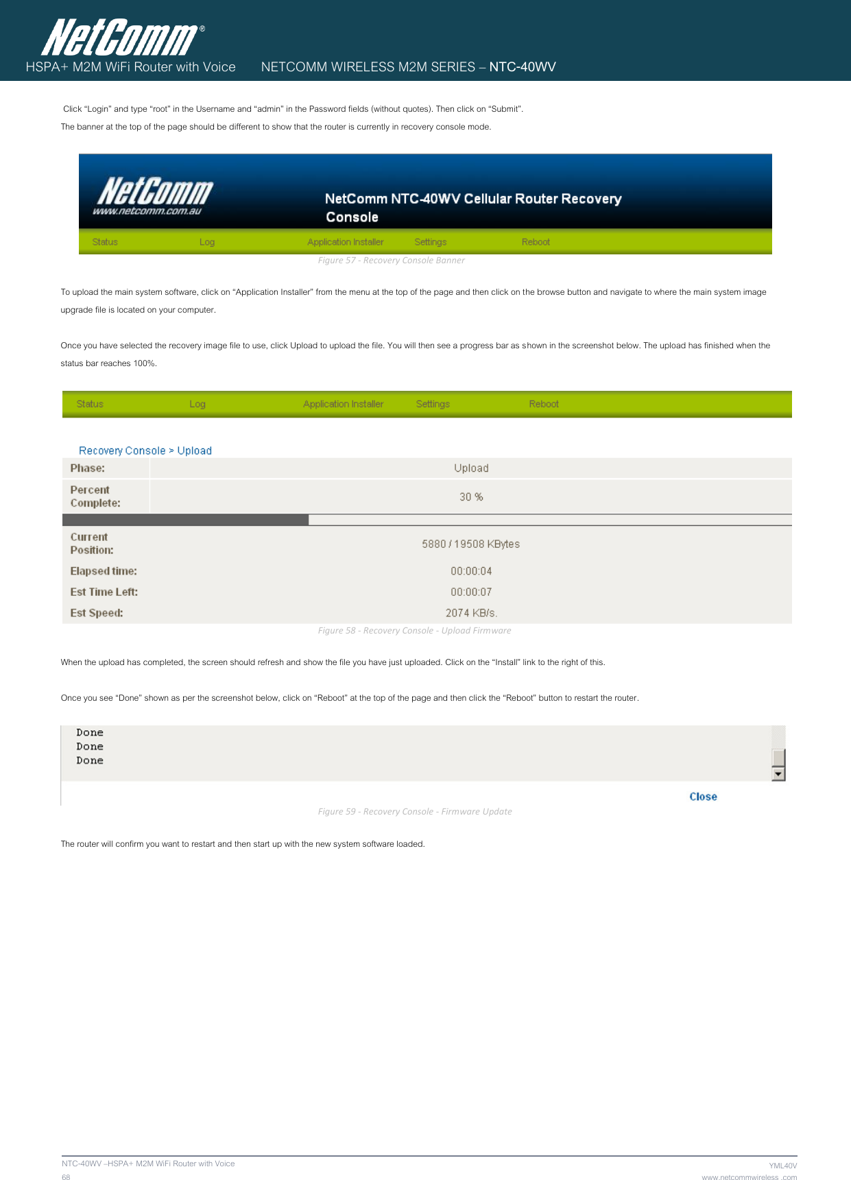
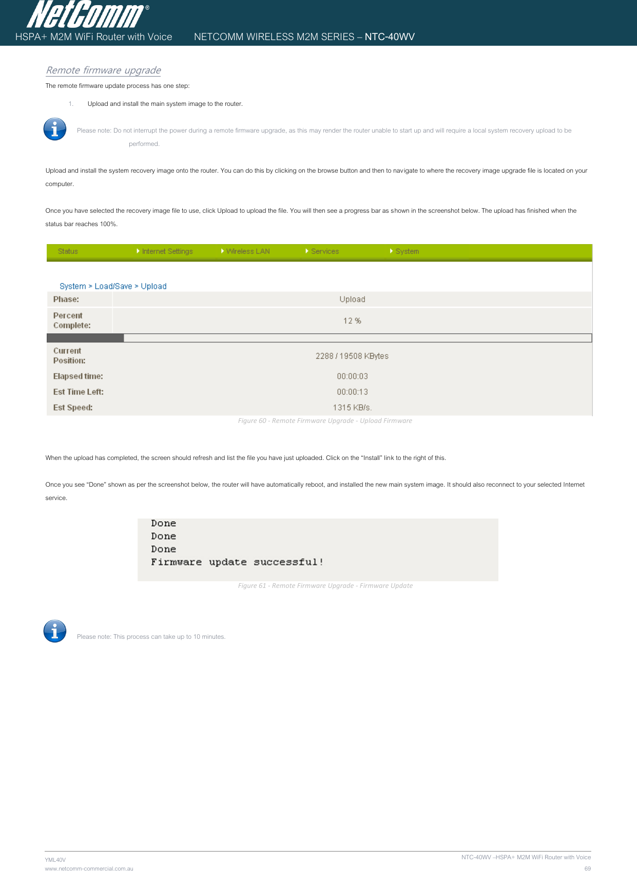
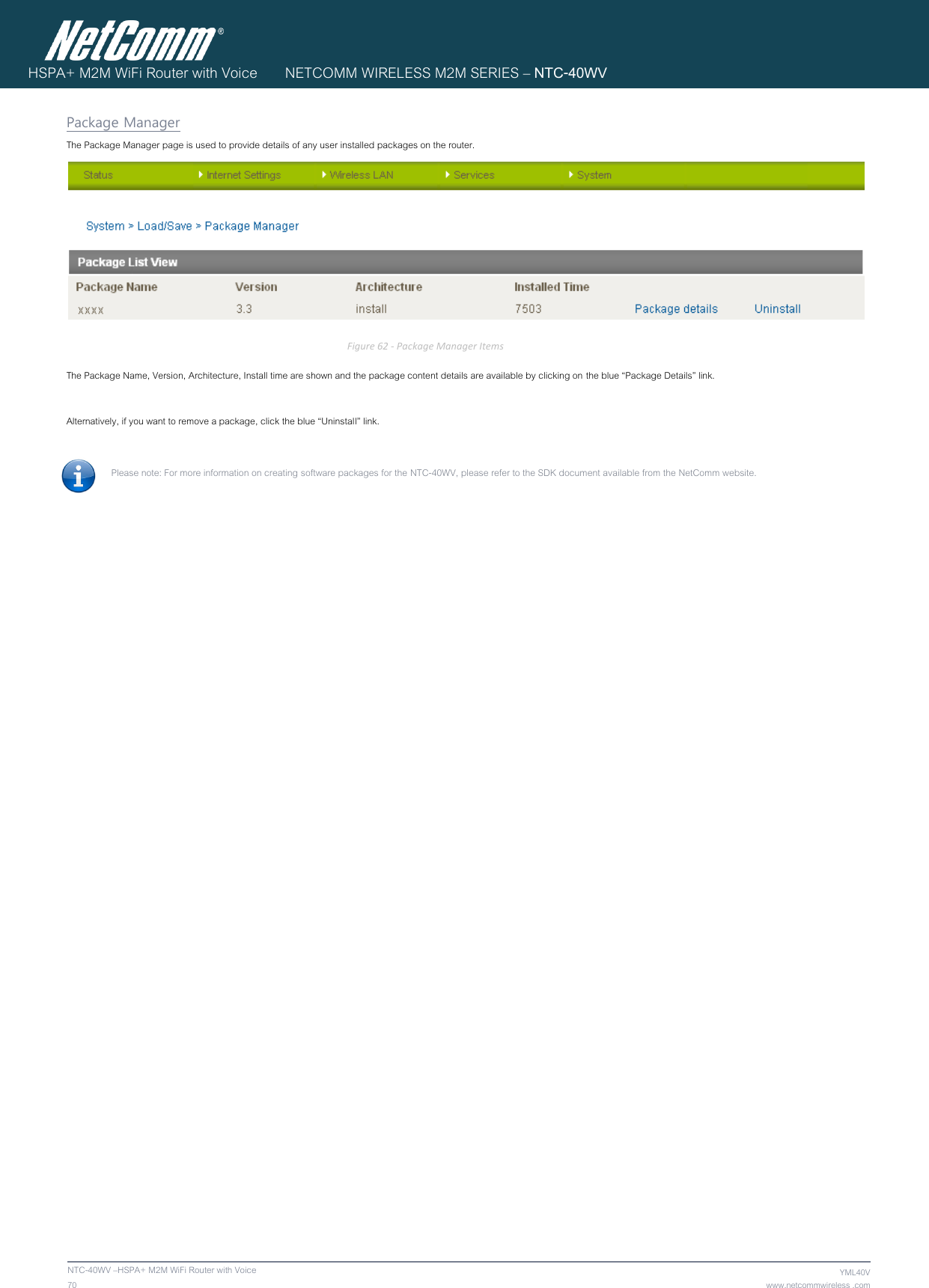

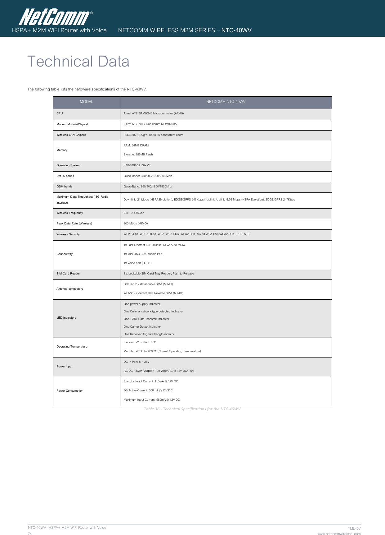
![YML40V www.netcomm-commercial.com.au NTC-40WV –HSPA+ M2M WiFi Router with Voice 73 HSPA+ M2M WiFi Router with Voice NETCOMM WIRELESS M2M SERIES – NTC-40WV System Configuration The System configuration page is used to specify an external syslog server and the TCP Keepalive settings. TCP Keepalive can be used to ensure the WWAN connection does not disconnect due to inactivity. Figure 64 - System Configuration Items OPTION DEFINITION IP / Hostname [:PORT] The IP address and port of the external syslog server you would like logging information sent to. Keepalive Enable or Disable the TCP Keepalive function. Keepalive Time The interval between the last packet sent and the first TCP keepalive packet being sent. Keepalive Interval The time between subsequent TCP Keepalive packets. Keepalive Probes The number of TCP Keepalive packets to send. Table 35 - System Configuration Items Logoff The logoff item will log you out of your web configuration session. Figure 65 - Logoff Reboot The reboot item will reboot the router. This can be useful if you have made configuration changes you want to implement or want to reboot the router. Figure 66 - Reboot Router](https://usermanual.wiki/NetComm-Wireless/NTC40WV/User-Guide-1785478-Page-73.png)