NetComm Wireless NWL1201 3G LIGHT INDUSTRIAL M2M ROUTER User Manual
NetComm Wireless Limited 3G LIGHT INDUSTRIAL M2M ROUTER
User Manual
N
N
WL-1
2
2
Series
– 3G L
i
U
s
i
ght In
d
s
er
d
ustria
l
Gu
i
l M2M
i
de
Route
r
r

2
Net
C
Cop
Cop
The
con
s
Sav
e
Wh
e
The
elec
Ple
a
Th
i
Net
C
Net
C
C
omm Wireless 3G Li
g
y
righ
t
y
right© 2013 NetCo
m
information containe
s
ent of NetComm Wi
r
Note: This d
e
our environment
e
n this equipment ha
s
cardboard box, the
p
tronic equipment alo
se be responsible a
n
i
s manual co
v
C
omm Wireless NWL
C
omm Wireless NWL
g
ht Industrial M2M Ro
u
m
m Wireless Limited
d herein is proprieta
r
r
eless.
ocument is subject t
o
s
reached the end o
f
p
lastic contained in t
o
ng with your househ
o
n
d protect our enviro
v
ers the follo
w
-12-01
-12-02
u
te
r
. All rights reserved.
r
y to NetComm Wirel
o
change without no
t
f
its useful life, it mus
t
he packaging, and t
h
o
ld waste. You may
b
nment.
w
ing product
s
ess. No part of this
d
t
ice.
t
be taken to a recyc
l
h
e parts that make u
p
b
e subject to penalti
e
s
:
d
ocument may be tra
ling centre and proc
e
p this device can be
e
s or sanctions und
e
nslated, transcribed
,
e
ssed separately fro
m
recycled in accord
a
e
r the law. Instead, a
s
reproduced, in any
f
m
domestic waste.
nce with regionally e
s
k for disposal instru
c
form, or by any mea
e
stablished regulatio
n
c
tions from your mu
n
www.netcommwire
l
n
s without prior writt
e
n
s. Never dispose of
n
icipal government.
l
ess.com
e
n
this

www
T
Ov
e
Pr
o
Ph
y
Pl
a
Ins
Ad
v
St
a
Int
Se
r
Sy
s
Ap
p
Ap
p
Ap
p
Ap
p
Ap
p
Ap
p
Sa
f
.netcommwireless.com
Initial docume
n
T
ab
l
e
rview .. ... ..
.
Introduction .............
Target audience ......
Prerequisites ...........
Notation ...................
o
duct int rodu
c
Product overview ....
Package contents ...
Product features ......
y
sical dimens
i
Physical dimension
s
LED indicators .........
Ethernet port LED in
Interfaces ................
a
cement of t h
e
Mounting options ....
t allat ion and
Powering the router .
Power consumption
Installing the router .
v
anced conf i
g
a
tus ...........
.
e
rnet .........
.
Data Connection .....
Connect on Deman
d
Operator Settings ....
SIM security setting
s
LAN .........................
Routing ....................
VPN .........................
r
vic e s . .. .. ... .
.
Dynamic DNS ..........
Network time (NTP) .
Data stream manag
e
Watchdogs ..............
SNMP ......................
TR-069 .....................
GPS .........................
SMS messaging ......
Diagnostics .............
Sending an SMS Di
a
s
t em . .. .. .. .. .
.
Log ..........................
System Configuratio
HTTPS key manage
m
SSH Key Managem
e
p
endix A: Ta
b
p
endix B: De
v
p
endix C: Mo
u
p
endix D: De
f
Restoring factory d
e
Recovery mode .......
p
endix E: HT
T
p
endix F: RJ-
4
f
et y and prod
u
nt release
l
e
o
.
................
.
.....................................
.
.....................................
.
.....................................
.
.....................................
c
tion ..........
.
.....................................
.
.....................................
.
.....................................
i
ons and indi
c
s
....................................
.
.....................................
dicators ........................
.
.....................................
e
r
out er .. ... .
.
.....................................
conf igurat ion
.
.....................................
.....................................
.
.....................................
g
urat i on . . . . . ..
.
................
.
................
.
.....................................
d
....................................
.
.....................................
s
....................................
.
.....................................
.
.....................................
.
.....................................
.
................
.
.....................................
.
.....................................
er
..................................
.
.....................................
.
.....................................
.
.....................................
.
.....................................
.
.....................................
.
.....................................
a
gnostic Command ......
.
................
.
.....................................
o
n ...................................
m
ent .............................
e
nt .................................
b
les . ... .. .. ... .
v
ice Mount ing
u
nt ing Bracke
t
f
ault Set t ings.
e
fault settings ................
.
.....................................
T
PS - Uploadi
n
4
5 connect or
u
ct care . .. ...
o
f C
o
................
.....................................
.....................................
.....................................
.....................................
................
.....................................
.....................................
.....................................
c
at ors . .. . .. .. .
.....................................
.....................................
.....................................
.....................................
................
.....................................
of t he 3G Li
g
.....................................
.....................................
.....................................
................
................
................
.....................................
.....................................
.....................................
.....................................
.....................................
.....................................
.....................................
................
.....................................
.....................................
.....................................
.....................................
.....................................
.....................................
.....................................
.....................................
.....................................
.....................................
................
.....................................
.....................................
.....................................
.....................................
................
Dimension s . .
t
...............
................
.....................................
.....................................
n
g a sel
f
-sign
e
................
................
DOCUMENT
V
Table
1
o
nt
e
................
.
.
.....................................
.
.....................................
.
.....................................
.
.....................................
................
.
.
.....................................
.
.....................................
.
.....................................
................
.
.
.....................................
.
.....................................
.
.....................................
.
.....................................
................
.
.
.....................................
g
ht Indust rial
M
.
.....................................
.
.....................................
.
.....................................
................
.
................
.
................
.
.
.....................................
.
.....................................
.
.....................................
.
.....................................
.
.....................................
.
.....................................
.
.....................................
................
.
.
.....................................
.
.....................................
.
.....................................
.
.....................................
.
.....................................
.
.....................................
.
.....................................
.
.....................................
.
.....................................
.
.....................................
................
.
.
.....................................
.
.....................................
.
.....................................
.
.....................................
................
.
................
.
................
.
................
.
.
.....................................
.
.....................................
e
d cert if icat e
.
................
.
................
.
V
ERSION
1
- Document Revisio
n
e
nt
s
.
................
.
.....................................
.
.....................................
.
.....................................
.
.....................................
.
................
.
.....................................
.
.....................................
.
.....................................
.
................
.
.....................................
.
.....................................
.
.....................................
.
.....................................
.
................
.
.....................................
M
2M rout er . .
.
.....................................
.
.....................................
.
.....................................
.
................
.
................
.
................
.
.....................................
.
.....................................
.
.....................................
.
.....................................
.
.....................................
.
.....................................
.
.....................................
.
................
.
.....................................
.
.....................................
.
.....................................
.
.....................................
.
.....................................
.
.....................................
.
.....................................
.
.....................................
.
.....................................
.
.....................................
.
................
.
.....................................
.
.....................................
.
.....................................
.
.....................................
.
................
.
................
.
................
.
................
.
.....................................
.
.....................................
.
................
.
................
.
................
n
History
s
................
.....................................
.....................................
.....................................
.....................................
................
.....................................
.....................................
.....................................
................
.....................................
.....................................
.....................................
.....................................
................
.....................................
................
.....................................
.....................................
.....................................
................
................
................
.....................................
.....................................
.....................................
.....................................
.....................................
.....................................
.....................................
................
.....................................
.....................................
.....................................
.....................................
.....................................
.....................................
.....................................
.....................................
.....................................
.....................................
................
.....................................
.....................................
.....................................
.....................................
................
................
................
................
.....................................
.....................................
................
................
................
N
e
................
.
.
.....................................
.
.....................................
.
.....................................
.
.....................................
................
.
.
.....................................
.
.....................................
.
.....................................
................
.
.
.....................................
.
.....................................
.
.....................................
.
.....................................
................
.
.
.....................................
................
.
.
.....................................
.
.....................................
.
.....................................
................
.
................
.
................
.
.
.....................................
.
.....................................
.
.....................................
.
.....................................
.
.....................................
.
.....................................
.
.....................................
................
.
.
.....................................
.
.....................................
.
.....................................
.
.....................................
.
.....................................
.
.....................................
.
.....................................
.
.....................................
.
.....................................
.
.....................................
................
.
.
.....................................
.
.....................................
.
.....................................
.
.....................................
................
.
................
.
................
.
................
.
.
.....................................
.
.....................................
................
.
................
.
................
.
etComm Wireless 3G
................
.
.
.....................................
.
.....................................
.
.....................................
.
.....................................
................
.
.
.....................................
.
.....................................
.
.....................................
................
.
.
.....................................
.
.....................................
.
.....................................
.
.....................................
................
.
.
.....................................
................
.
.
.....................................
.
.....................................
.
.....................................
................
.
................
.
................
.
.
.....................................
.
.....................................
.
.....................................
.
.....................................
.
.....................................
.
.....................................
.
.....................................
................
.
.
.....................................
.
.....................................
.
.....................................
.
.....................................
.
.....................................
.
.....................................
.
.....................................
.
.....................................
.
.....................................
.
.....................................
................
.
.
.....................................
.
.....................................
.
.....................................
.
.....................................
................
.
................
.
................
.
................
.
.
.....................................
.
.....................................
................
.
................
.
................
.
Light Industrial M2M
R
DATE
.
................
.....................................
.....................................
.....................................
.....................................
.
................
.....................................
.....................................
.....................................
.
................
.....................................
.....................................
.....................................
.....................................
.
................
.....................................
.
................
.....................................
.....................................
.....................................
.
................
.
................
.
................
.....................................
.....................................
.....................................
.....................................
.....................................
.....................................
.....................................
.
................
.....................................
.....................................
.....................................
.....................................
.....................................
.....................................
.....................................
.....................................
.....................................
.....................................
.
................
.....................................
.....................................
.....................................
.....................................
.
................
.
................
.
................
.
................
.....................................
.....................................
.
................
.
................
.
................
R
oute
r
3
.. 5
........ 5
........ 5
........ 5
........ 5
.. 6
........ 6
........ 6
........ 7
.. 8
........ 8
........ 9
...... 10
...... 11
. 12
...... 12
. 18
...... 18
...... 19
...... 19
. 20
. 21
. 24
...... 24
...... 28
...... 32
...... 33
...... 37
...... 41
...... 51
. 65
...... 65
...... 66
...... 67
...... 69
...... 72
...... 74
...... 75
...... 78
...... 82
...... 85
. 92
...... 92
...... 96
.... 103
.... 107
111
112
114
115
.... 116
.... 117
118
120
121

4
NetComm Wireless 3G Light Industrial M2M Route
r
www.netcommwireless.com

www
O
I
n
This
T
a
This
P
r
Bef
o
N
The
.netcommwireless.com
O
v
e
n
trodu
c
document provides
a
rget
a
document is intend
e
r
ereq
u
o
re continuing with th
A de
v
A we
b
A flat
h
N
otatio
n
following symbols a
r
The followin
g
The followi
n
The followi
n
e
rvi
e
c
tion
you all the informati
o
a
udien
c
e
d for system integra
u
isites
e installation of your
v
ice with a working E
t
b
browser such as In
h
ead screwdriver if fi
n
r
e used in this user g
g
note requires atte
n
n
g note provides a
w
n
g note provides use
f
e
w
o
n you need to set u
p
c
e
tors or experienced
h
3G Light Industrial
M
t
hernet network ada
p
ternet Explorer, Moz
i
eld terminated pow
e
uide:
n
tion.
w
arning.
f
ul information.
p
, configure and use
h
ardware installers
w
M
2M Router, please
c
p
ter.
lla Firefox or Google
r is required.
the NetComm Wirel
e
w
ho understand tele
c
c
onfirm that have the
Chrome.
e
ss NWL-12 3G Ligh
t
c
ommunications term
following:
N
e
Industrial M2M Rou
t
inology and concept
etComm Wireless 3G
t
e
r
.
t
s.
Light Industrial M2M
R
R
oute
r
5

6
NetComm Wireless 3G Light Industrial M2M Route
r
www.netcommwireless.com
Product introduction
Product overview
Penta-band 3G with quad-band 2G auto-fallback
HSPA+ up to 14.4 Mbps DL
Ethernet port with full passive Power over Ethernet (PoE) support (802.3af) (NWL-12-01 only)
RS232/RS422/RS485 Port and USB 2.0 OTG port
Integrated ZigBee multipoint mesh wireless networking (NWL-12-01 only)
Built in GPS supporting an active or passive GPS Antenna via external SMA connector
Three multi-purpose I/O ports
One dedicated ignition input
Internal diversity antennas with option for external main antenna (autosensing)
Intelligent, Tri-Colour LED display for clear, easy to read modem status information
Extensive device management with support for TR-069, Web GUI and full feature management with SMS
Flexible mounting suitable for in-home use or industrial applications with built-in wall mount and DIN rail mounting options
Package contents
The NetComm Wireless 3G Light Industrial M2M Router package consists of:
1 x 3G Light Industrial M2M Router
2 x 3G antennas
1 x 1.5m yellow Ethernet cable 8P8C
1 x DIN rail mounting bracket
1 x six-way terminal block
1 x quick start guide and safety manual
If any of these items are missing or damaged, please contact NetComm Wireless Support immediately. The NetComm Wireless Support website can be found at:
http://support.netcommwireless.com.

www
P
r
The
pro
v
hav
e
The
con
s
ope
n
The
.netcommwireless.com
r
oduct
NetComm Wireless
N
v
ide state-of-the-art f
e
e
an Internet connec
t
3G Light Industrial
M
s
erve usage; TR-069
n
management syste
NetComm Wireless
3
f
eatur
e
N
WL-12 3G Light In
d
e
atures and versatilit
y
t
ion via the use of S
M
M
2M Router includes
support for easy m
a
m allows you to exp
a
3
G Light Industrial M
e
s
d
ustrial M2M Router i
s
y
at an affordable pr
i
M
S diagnostics and
c
many features such
a
nagement of a grou
p
a
nd the feature set b
y
2M Router meets th
e
s
an M2M device de
s
ce. Compatible with
ommands.
as Dial on Demand
w
p
of 3G Light Industri
y
producing your ow
e
global demand for
a
s
igned by NetComm
network worldwide,
t
w
hich provides a me
al M2M routers; and
w
n custom software a
p
a
reliable and cost-e
f
Wireless to address
t
he 3G Light Industri
a
ans to seamlessly c
o
the ability to functio
n
p
plications.
f
fective M2M device
N
e
the rapid growth in
M
a
l M2M Router can
b
o
nnect or disconnect
n
as an SSH server t
o
that successfully cat
etComm Wireless 3G
M
2M deployments. I
t
b
e managed remotel
y
t
the mobile broadba
o
secure communica
t
ers to mass deploy
m
Light Industrial M2M
R
t
has been designed
y
even when it does
n
n
d connection to
tions.
A
dditionally, t
h
m
ent across busines
s
R
oute
r
7
to
n
ot
h
e
s
es.
8
Net
C
P
i
P
h
Bel
o
C
omm Wireless 3G Li
g
P
hy
s
ndi
h
ysica
l
o
w is a list of the phy
s
g
ht Industrial M2M Ro
u
s
ic
a
cat
o
l
dime
n
s
ical dimensions of t
h
u
te
r
a
l d
i
o
rs
n
sions
h
e 3G Light Industri
a
i
m
e
l M2M Router.
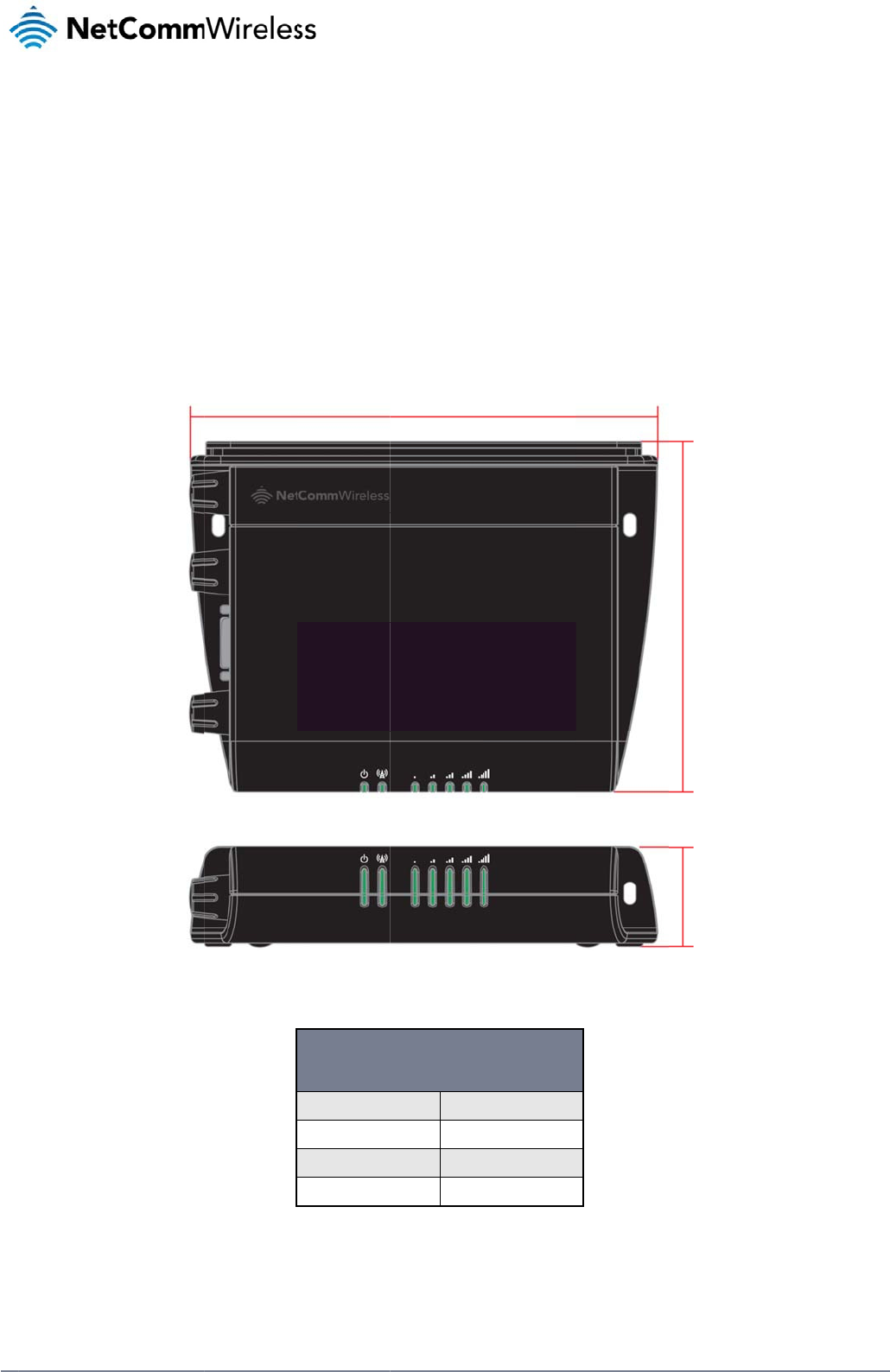
Figure 1 – 3G L
ig
3G LIG
H
(WITHOUT E
X
Length
Depth
Height
Weight
T
a
b
e
nsi
o
ig
ht Industrial M2M
R
H
T INDUSTRIAL M2
M
XTERNAL ANTENN
A
140 mm
103 mm
30 mm
b
le
2 - Device Dimen
s
o
n
s
R
oute
r
Dimensions
M
ROUTER
A
S ATTACHED)
s
ion
s
s
an
d
d
www.netcommwire
l
l
ess.com
www
L
E
The
1
Th
e
.netcommwireless.com
E
D ind
3G Light Industrial
M
L
E
e
term “blinking” mean
s
d
icator
s
M
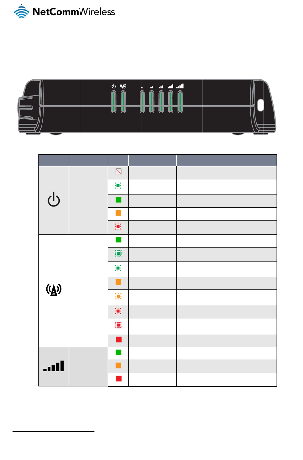
2M Router uses 7 L
E
E
D ICON
Power
Netwo
r
Signal
s
that the LED may puls
s
E
Ds to display the c
u
NAME
r
k
strength
e, with the intervals tha
t
u
rrent system and co
Figure 2 - 3G Lig
h
COLOUR
Off
Double
f
On
On
Slow fla
s
On
Blinking
1
Slow fla
s
On
Slow fla
s
Slow fla
s
Fast flas
On
On
On
On
T
t
the LED is on and off
n
nnection status.
gh
t Industrial M2M Ro
u
STATE
f
lash
s
hing
1
s
hing
s
hing
s
hing
s
hing
T
able
3 - LED Indicat
o
n
ot being equal. The te
u
te
r
LED Indicators
Power off
Powering up
Power on
Power on in recove
r
Hardware error
Connected via WW
A
Traffic via WWAN
Connecting PDP
Registered network
Registering networ
k
SIM PIN locked
SIM PUK locked
Can’t connect
3G
2G GPRS
GSM only (no GPR
S
o
r
s
rm “flashing” means th
a
N
e
DESCRIPTI
O
r
y mode
A
N
S
)
a
t the LED turns on and
etComm Wireless 3G
ON
d
off at equal intervals.
Light Industrial M2M
R
R
oute
r
9
10
NetComm Wireless 3G Light Industrial M2M Route
r
www.netcommwireless.com
Signal strength LEDs
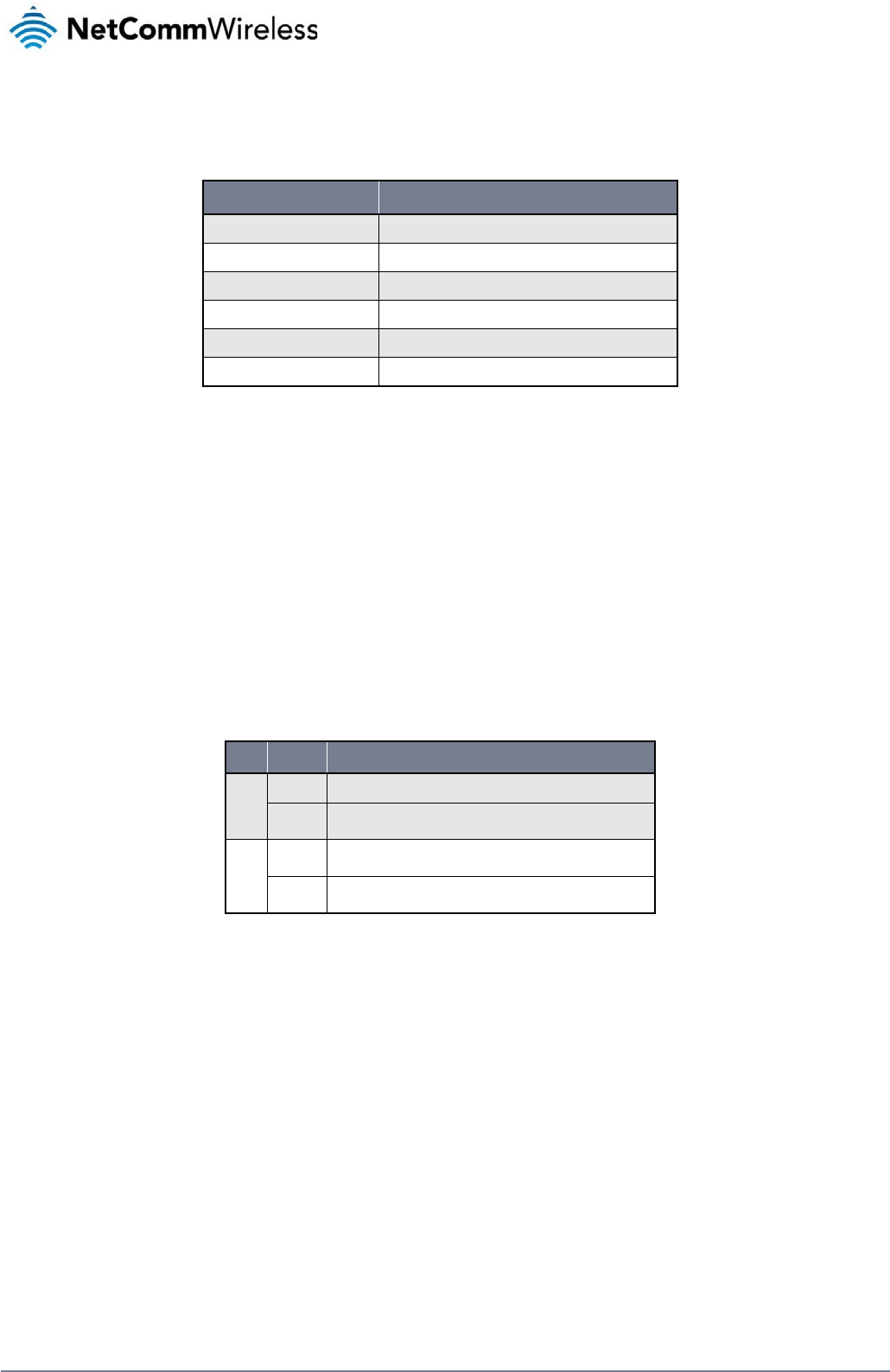
The following table lists the signal strength range corresponding with the number of lit signal strength LEDs.
NUMBER OF LIT LEDS SIGNAL STRENGTH
All LEDs unlit < -109 dBm
1 -109 dBm to -101dBm
2 -101 dBm to -91 dBm
3 -91 dBm to -85 dBm
4 -85 dBm to -77 dBm
5 > -77 dBm
Table 4 - Signal strength LED descriptions
LED update interval
The signal strength LEDs update within a few seconds with a rolling average signal strength reading. When selecting a location for the router or connected or positioning an external antenna,
please allow up to 20 seconds for the signal strength LEDs to update before repositioning.
Ethernet port LED indicators
The Ethernet port of the 3G Light Industrial M2M Router has two LED indicators on it.
Figure 3 - Ethernet port LED indicators
The table below describes the statuses of each light and their meanings.
LED STATUS DESCRIPTION
Green
On There is a valid network link.
Blinking There is activity on the network link.
Amber
On The Ethernet port is operating at a speed of 100Mbps.
Off The Ethernet port is operating at a speed of 10Mbps or no Ethernet cable is connected.
Table 5 - Ethernet port LED indicators description
www
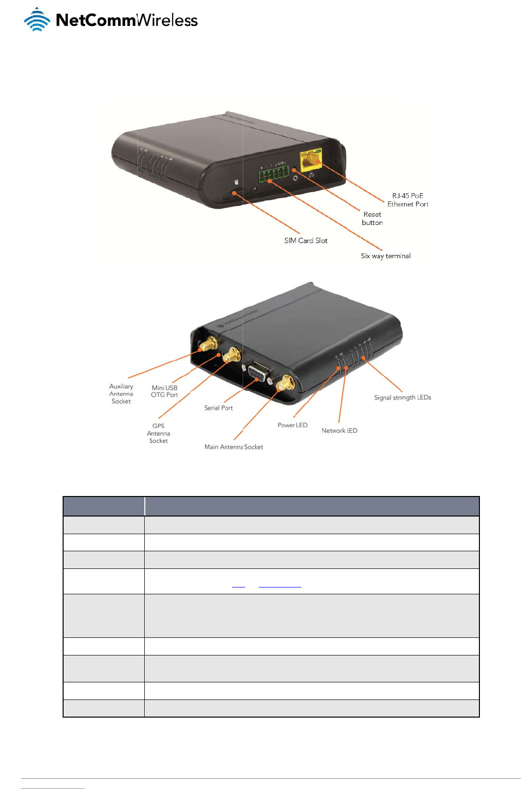
I
n
The
.netcommwireless.com
n
terfac
e
following interfaces
a
Main an
t
Auxiliar
y
GPS ant
e
Six-way
Reset b
u
SIM car
d
RJ45 Po
Mini US
B
Serial p
o
e
s
a
re available on the
3
ITEM
t
enna socket
y
antenna socket
enna socket
terminal block connector
u
tton
d
slot
E Ethernet port
B
2.0 OTG port
o
rt
3
G Light Industrial M
SMA female connec
SMA female connec
SMA female connec
Connect power sou
r
Refer to the diagra
m
Press and hold for l
e
Press and hold for 5
Press and hold for 1
Insert SIM card her
e
Connect one or sev
e
supply can serve as
Provides connectivi
t
Female DB9 port su
2
M Router:
tor for main antenna.
tor for auxiliary antenna.
tor for GPS antenna.
r
ce, ignition and I/O wires
h
m
and table on under Step
3
e
ss than 5 seconds to reb
o
to 15 seconds to reboot t
o
5 to 20 seconds to reset t
h
e
.
e
ral devices via a network
s
a backup power source if
y for optional external stor
a
p
porting 9-wire RS-232, R
S
Figure 4 - Interface
s
D
h
ere. Power, ignition and I
/
3
of the Installing your dev
o
ot to normal mode.
o
recovery mode.
h
e router to factory default
switch here. This port can
f
required (PoE available o
n
a
ge or a USB Ethernet do
n
S
-485 or RS-422 (software
Table 6 – Interface
s
s
D
ESCRIPTION
/
O wires may be terminate
d
ice section for correct wiri
n
settings.
also optionally receive Po
w
n
NWL-12-01 only).
n
gle. Supplies up to 0.5A t
o
selectable).
s
N
e
d
on optional terminal bloc
k
n
g of the terminal block. O
p
w
er over Ethernet (802.3af
o
connected device.
etComm Wireless 3G
k and connected to DC in
p
perates in the 8-40V DC r
a
PoE) in which case the D
C
Light Industrial M2M
R
p
ut jack.
nge.
C
power
R
oute
r
11
12
Net
C
P
The
adju
M
The
M
o
Wh
e
C
omm Wireless 3G Li
g
P
la
c
two external high-pe
sting the orientation
Note: When
s
M
ounti
n
3G Light Industrial
M
o
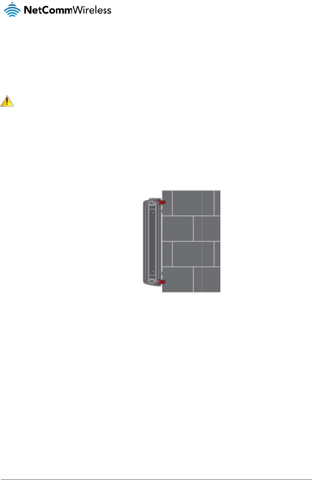
unted fl
a
e
n mounted flat agai
n
g
ht Industrial M2M Ro
u
c
e
m
e
rformance antennas
of the antennas. If y
o
s
electing a location f
o
n
g opti
o
M
2M router can be q
u
a
t against t
h
n
st the wall, the 3G L
i
u
te
r
m
ent
supplied with the ro
u
o
u are unable to get
a
o
r the router, allow a
t
o
ns
u
ickly and easily mo
u
h
e wall
i
ght Industrial M2M r
o
of
t
u
ter are designed to
a
n acceptable signa
l
t
least 20 seconds fo
u
nted in a variety of l
o
o
uter has a slimline f
Figure 5 -
W
t
he
provide optimum si
g
l, try moving the rout
e
o
r the signal strength
o
cations.
f
orm factor. Use app
r
W
all moun
t
- Flat ag
a
ro
u
g
nal strength in a wid
e
r to a different plac
e
LEDs to update bef
o
r
opriately sized scre
w
a
inst the wall
u
ter
e
range of environm
e
e
or mounting it diffe
r
o
re trying a different l
w
s in the mounting h
o
e
nts. If you find the
s
r
ently.
l
ocation or connecti
n
o
les provided on the
www.netcommwire
l
ignal strength is we
a
n
g an external anten
n
base of the unit.
l
ess.com
a
k, try
n
a.
www
P
e
If a l
app
r
C
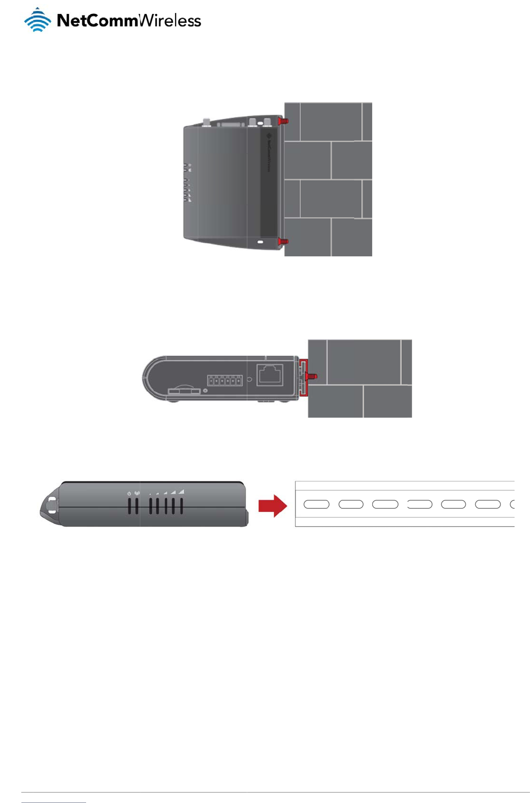
The
To
m
.netcommwireless.com
e
rpendicu
l
arge surface area is
r
opriately sized scre
w
Section D
I
3G Light Industrial
M
m
ount the unit on a C
-
l
ar to the
w
not available, there i
w
s in the mounting h
o
I
N Rail m
o
M
2M router easily sli
d
-
Section DIN rail, sli
d
w
all
s the option of moun
o
les provided on the
o
unt
d
es onto a C Section
d
e it on as illustrated
t
ing the router perpe
back of the unit.
Figure 6 - W
a
DIN rail so that it is h
Figur
e
below:
Figure 8
-
e
ndicular to the wall.
T
a
ll moun
t
- Perpendi
cu
h
orizontally mounted.
e
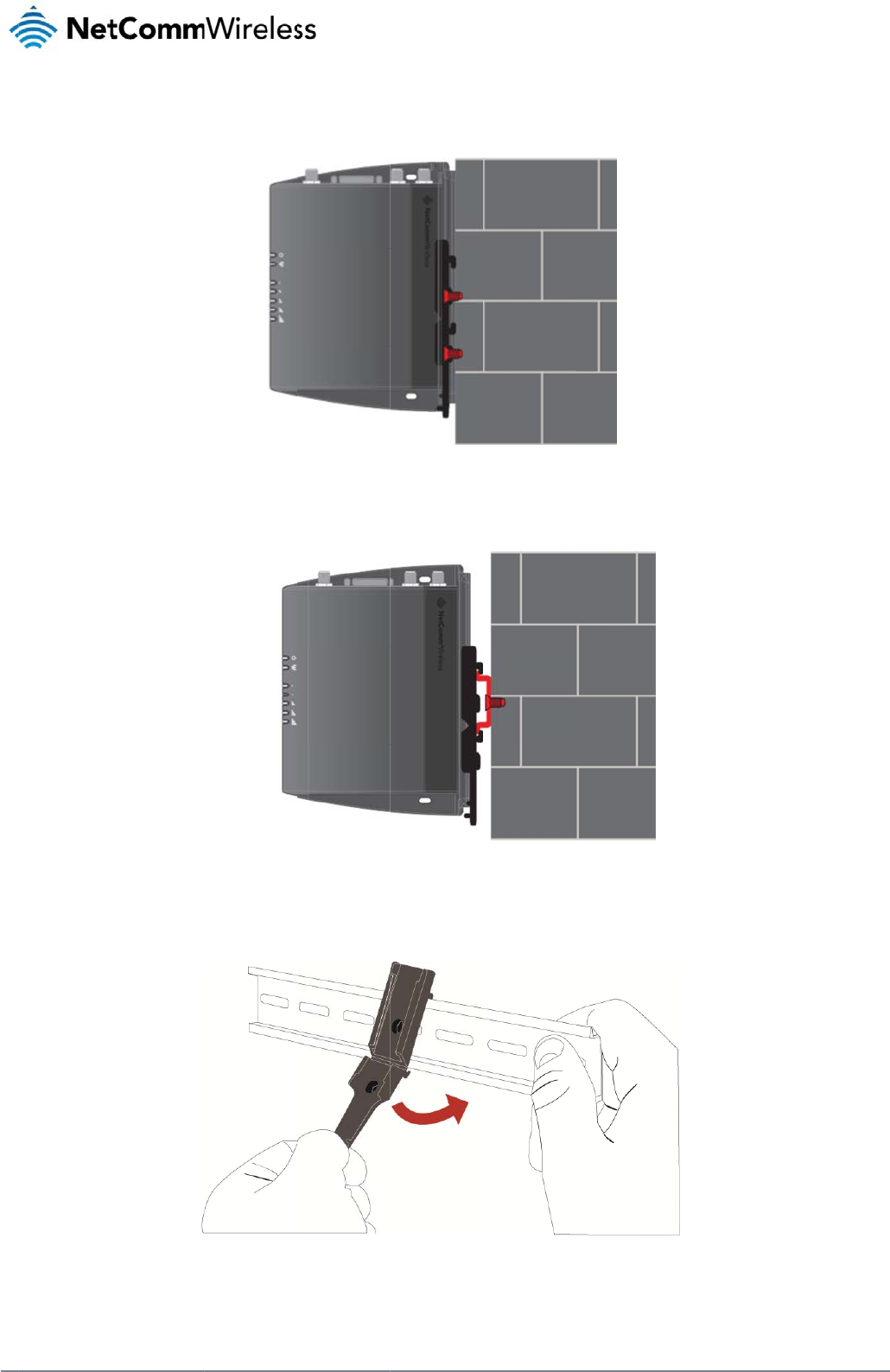
7 - C Section DIN ra
i
- Mounting the unit o
n
T
his gives the router
cu
lar to the wall
The DIN Rail mounti
i
l moun
t
n
a DIN rail
N
e
a small wall footprin
t
ng bracket is not re
q
etComm Wireless 3G
t
while remaining se
c
q
uired for C Section
D
Light Industrial M2M
R
c
urely attached. Use
D
IN rail mounting.
R
oute
r
13
14
NetComm Wireless 3G Light Industrial M2M Route
r
www.netcommwireless.com
Mounting bracket
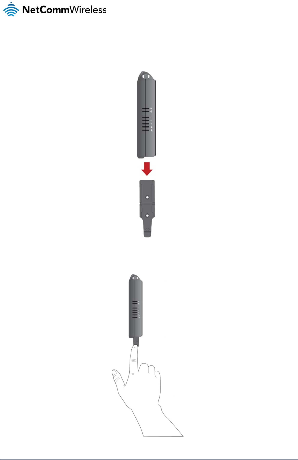
The provided mounting bracket provides additional methods of mounting the 3G Light Industrial M2M router.
To attach the mounting bracket, slide it onto the rear of the router as shown in the diagram below:
Figure 9 - Sliding on the mounting bracket
To remove the bracket, press the PUSH button and slide the router off the bracket:
Figure 10 - Removing the mounting bracket

www
.netcommwireless.com
N
e
etComm Wireless 3G
Light Industrial M2M
R
R
oute
r
15
16
Net
C
U
s
By fi
U
s
The
Alte
r
C
omm Wireless 3G Li
g
s
ing the
m
rst attaching the DI
N
s
ing the
m
3G Light Industrial
M
r
natively, you can att
a
g
ht Industrial M2M Ro
u
m
ounting b
r
N
rail bracket to the
w
m
ounting b
r
M
2M router may be v
e
a
ch it to the DIN Rail
u
te
r
r
acket for
w
all, the 3G Light Ind
u
r
acket for
e
rtically mounted to
t
by using the V ben
d
Figu
r
wall mou
n
u
strial M2M router c
a
Figure 11 – Wa
l
Top hat
D
t
he wall with the bra
c
Figur
e
d
in the bracket as ill
u
r
e
13 -
A
ttaching the
m
n
ting
a
n be easily attache
d
al
l moun
t
- Mounted v
ia
D
IN rail m
o
c
ket by sliding the br
a
re
12 -
T
op hat DIN ra
il
u
strated below:
m
ounting bracket to
t
d
and removed from
t
ia
DIN rail bracke
t
o
unting
a
cket onto a top hat
D
il
moun
t
th
e DIN rail using th
e
V
he bracket.
D
IN rail
V
bend
www.netcommwire
l
l
ess.com

www
D
e
In si
t
.netcommwireless.com
e
sk moun
t
t
uations where wall
m
t
m
ounts and DIN rails
are not required, yo
u
u
can simply place t
h
F
h
e 3G Light Industria
F
igure
14 - Desk mo
u
l M2M router on a d
e
u
n
t
N
e
e
sk using its rubber f
e
etComm Wireless 3G
e
et to prevent it from
Light Industrial M2M
R
slipping.
R
oute
r
17
18
NetComm Wireless 3G Light Industrial M2M Route
r
www.netcommwireless.com
Installation and configuration
of the 3G Light Industrial M2M
router
Powering the router
The 3G Light Industrial M2M router can be powered in one of three ways:
1. Power over Ethernet (802.3af PoE) (available on the NWL-12-01 only)
2. DC power input via 6-pin connector (8-40V DC)
3. DC power input via field terminated power source (8-40V DC)
The green power LED on the router lights up when a power source is connected.
Power over Ethernet (802.3af PoE) (available on the NWL-12-01 only)
Power over Ethernet (PoE) is a method of connecting network devices through Ethernet cable where power and data are passed along a single cable. This may be a desirable method of
powering the device if PoE is available, or if it’s most convenient in the desired installation environment to only have a single cable running to the 3G Light Industrial M2M router.
There are 5 power classes defined in the IEEE 802.3-2005 standard, of which the 3G Light Industrial M2M router is a class 3 device.
CLASS CLASSIFICATION CURRENT POWER RANGE CLASS DESCRIPTION
3 26-30 mA 6.49 – 12.95 W Mid power
Table 7 - PoE power classes
To use PoE to power the 3G Light Industrial M2M router, simply connect your router to a PoE injector or PoE network switch using the bundled yellow Ethernet cable 8P8C.
DC power via 6-pin connector
The DC input jack can accept power from a separately sold DC power supply. Both a standard temperature range DC power supply and an extended temperature range DC power supply are
available to purchase as accessories.
To power the device via DC Power via the 6-pin connector, remove the attached green terminal block from your router and connect the external DC power supply to the router’s green DC power
jack.
DC power via field terminated power source
If an existing 8-40V DC power supply is available, you can insert the wires into the supplied terminal block to power your router. Use a No. 3 flathead screwdriver to tighten the terminal block
screws and secure the power wires, making sure the polarity of the wires are correctly matched, as illustrated below.
Figure 15 - Locking Power Terminal Block

www
F
a
The
inpu
the
D
Vi
You
Dev
e
To v
stat
u
P
o
To
a
con
d
net
w
A
v
I
n
Afte
r
.netcommwireless.com
a
ilover po
w
3G Light Industrial
M
t jack of the router, t
h
D
C input jack, witho
u
i
ewing po
w
can view the curren
t
e
lopment Kit to acce
iew the router’s pow
e
u
s page.
o
wer
c
ssist with power con
d
itions. It’s important
w
ork activity.
v
erage po
w
n
stalli
n
r
you have mounted
t
1. Connect e
q
requires d
a
If you’re us
injector).
2. Ensure the
indicators
o
w
er supp
o
M
2M router includes
s
h
e router will source
u
t affecting the route
r
w
er sourc
e
t
power input mode i
n
ss this information fo
e
r source informatio
n
c
onsu
m
sumption planning, t
to note that this tabl
e
w
er cons
u
Powered on, idle
a
Powered on, con
n
Powered on, con
n
Peak power draw
n
g the
r
t
he router and conn
e
q
uipment that requir
e
a
ta access via the 3
G
ing PoE as the powe
external power sour
c
o
n the device with th
o
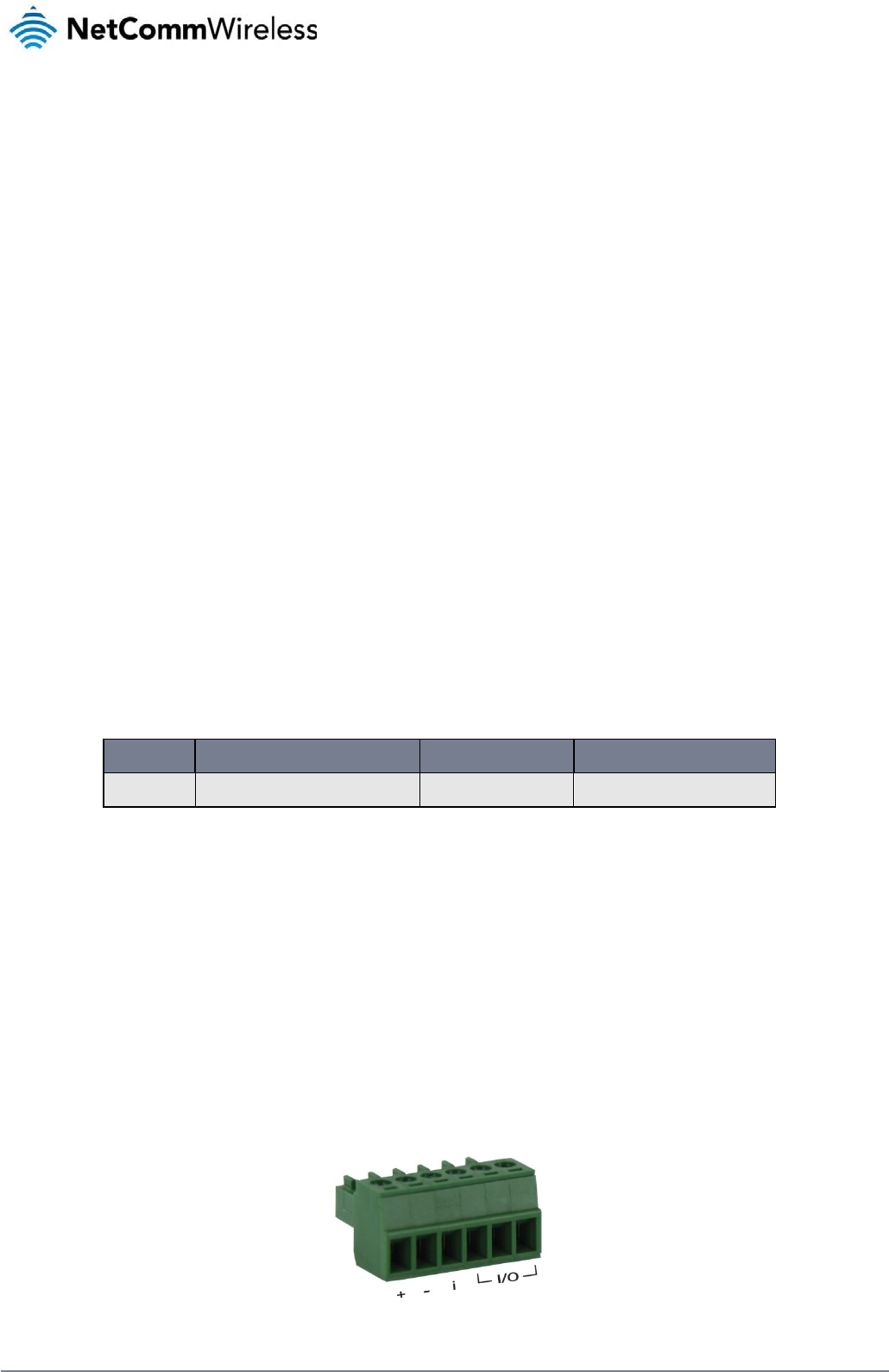
TERMINAL
+
-
i
I/O
o
rt (NWL-
1
s
upport for connecti
o
power exclusively fr
o
r
’s operation. When
P
e
informa
t
n
the Advanced stat
u
r advanced purpos
e
n
, log in to the router
m
ption
he following table su
e
serves as an indic
a
u
mption fi
g
a
nd connected to pa
n
ected to packet dat
a
n
ected to packet dat
a
at maximum 3G mo
d
r
outer
e
cted a power sourc
e
e
s network access to
G
Light Industrial M2
M
r source, you need t
o
c
e is switched on an
d
o
se listed on page 8
Positive wire for power
Ground wire.
Dedicated terminal for
Three terminals used f
o
Table 8
1
2-01 only
)
o
n of two power sour
c
o
m the PoE source. I
n
P
oE power is restore
d
t
ion
u
s section of the devi
s (e.g. configuring S
and expand the Adv
a
mmarises average
p
a
tion only as the po
w
g
ures
STATE
cket data
a
with average load
a
with heavy traffic
d
ule transmission po
w
Table 9 -
Av
e
, follow these steps
t
the Ethernet port of
y
M
router. You can co
n
o
connect any devic
e
d
wait 2 minutes for
y
of this guide.
DESC
R
r
.
ignition detection.
or input/output detection.
(
8
- Locking power blo
ck
)
c
es at the same tim
e
n
the event that pow
e
d
, the router automat
ce’s web user interf
a
MS alerts to inform
y
anced status box on
p
ower consumption
d
w
er consumed by the
w
e
r
Av
erage power consu
m
to complete the inst
a
your router. This ma
y
nnect one device di
r
e
s via an available d
a
y
our 3G Light Indust
r
R
IPTION
(
Please refer to the User G
u
ck
pin out
s
e
. When a PoE Ether
n
e
r from the PoE cabl
e
i
cally switches back
a
ce. This is useful for
ou of the power stat
u
the status page. Se
e
d
uring the various sta
device is affected b
y
m
ption figure
s
a
llation process.
y
be your computer f
o
r
ectly, or several dev
i
a
ta Ethernet port on
y
r
ial M2M router to st
a
N
e
u
ide).
et cable is connecte
e
is lost, the router w
i
t
o receive power fro
m
remotely monitoring
u
s of the router).
e
the Status section
o
t
es of the 3G Light I
n
y
many variables inc
l
POWER CONSUM
P
1.2W
2.0W
4.0W
5.0W
o
r advanced configu
ces using a network
y
our PoE power sour
a
rt up. To check the
s
etComm Wireless 3G
e
d and DC power is
a
w
ill automatically swit
c
m
the PoE input sou
r
the device. You ca
n
o
f this manual for mo
n
dustrial M2M router
luding signal strengt
P
TION
u
ration purposes, or
y
switch.
r
ce (be it a PoE netw
o
s
tatus of your router,
Light Industrial M2M
R
a
lso supplied to the
D
c
h to source power f
r
ce.
also use the Softwa
r
r
e information on the
under normal usage
h, network type, and
y
our end equipment
w
o
rk switch or PoE po
w
compare the LED
R
oute
r
19
D
C
r
om
r
e
w
hich
w
er
20
Net
C
A
The
To l
o
The
C
omm Wireless 3G Li
g
A
d
v
3G Light Industrial
M
o
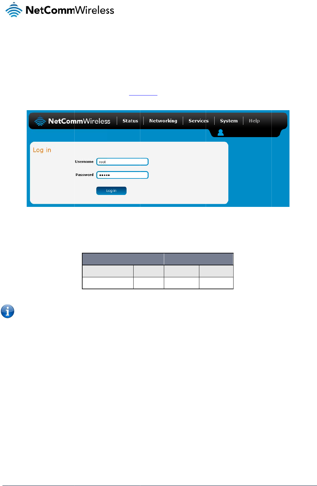
g in to the web-bas
e
1. Open a we
2. Enter the l
o
use one of
Note: To acc
e
For security r
e
then Adminis
t
Status page is displ
a
g
ht Industrial M2M Ro
u
v
an
c
M
2M Router comes
w
e
d user interface rou
t
b browse
r
(e.g. Inter
o
gin username and
p
the default account
d
e
ss all features of th
e
easons, we highly re
t
ration page.
a
yed when you log i
n
u
te
r
c
ed
w
ith preconfigured se
t
t
er:
net Explorer, Firefox
,
p
assword. If this is th
e
d
etails to log in.
ADMI
Username:
Password:
e
router, you must us
commend that you
c
n
successfully.
co
n
t
tings that should sui
Safari), type http://1
Figure 16 – Log i
n
e
first time you are lo
g
N MANAGER ACCO
a
d
a
d
Table 10 -
M
e
the root manager
a
hange the passwor
d
n
fi
g
t most customers. F
o
92.168.1.1 into the
a
n
prompt for the we
b
-
b
gging in or you have
O
UNT
d
min Us
e
d
min Pa
s
M
anagement accoun
t
a
ccount.
d
s for the root and a
d
g
ur
a
o
r advanced configu
r
ddress bar and pre
s
b
ased user interfac
e
not previously confi
g
ROOT MANAGER
A
e
rname: ro
o
s
sword: a
d
t
login detail
s
d
min accounts upon i
a
tio
n
r
ation, log in to the w
s Enter. The web-ba
g
ured the password
f
A
CCOUNT
ot
d
min
nitial installation. Yo
u
n
w
eb-based user inter
f
a
sed user interface l
o
for the “root” or “ad
m
u
can do so by navig
www.netcommwire
l
f
ace of the route
r
.
g in screen is displa
y
m
in” accounts, you c
a
ating to the System
a
l
ess.com
y
ed.
a
n
a
nd

www
S
The
Syst
butt
o
.netcommwireless.com
S
tat
u
status page of the w
em information, LAN
o
ns to show or hide t
u
s
eb interface provide
s
details, Cellular con
hem. Extra status bo
s
system related info
nection status, Pack
e
xes will appear as a
d
rmation and is displ
a
e
t data connection s
t
d
ditional software fe
a
Fi
g
a
yed when you log i
n
t
atus and Advanced
a
tures are enabled (
e
g
ure
17 -
T
he Status
p
to the 3G Light Ind
u
status details. You c
e
.g. VPN connectivit
y
p
age
N
e
strial M2M router m
a
a
n toggle the sectio
n
y
).
etComm Wireless 3G
a
nagement console.
T
n
s from view by click
Light Industrial M2M
R
T
he status page sho
w
ing the or
R
oute
r
21
w
s

22
NetComm Wireless 3G Light Industrial M2M Route
r
www.netcommwireless.com
ITEM DEFINITION
System information
System up time The current uptime of the router.
Board version The hardware version of the router.
Serial Number The serial number of the router.
Software The software version number running on the router.
Model The type of phone module and the firmware version of the module.
Firmware version The firmware revision of the phone module.
IMEI The International Mobile Station Equipment Identity number used to uniquely identify a mobile device.
LAN
IP The IP address and subnet mask of the router.
MAC Address The MAC address of the router.
Ethernet Port Status Displays the current status of the Ethernet port and its operating speed.
Cellular connection status
SIM Status Displays the activation status of the router on the carrier network.
Signal strength (dBm) The current signal strength measured in dBm
Network registration status The status of the router’s registration for the current network.
Operator selection The mode used to select an operator network.
Current operator The current operator network in use.
Roaming status The roaming status of the router.
Allowed bands The bands to which the router may connect.
Current band The current band being used by the router.
Coverage The mobile equipment identifier (MEID) of the router, a unique code for identifying devices on a CDMA network.
WWAN Connection Status
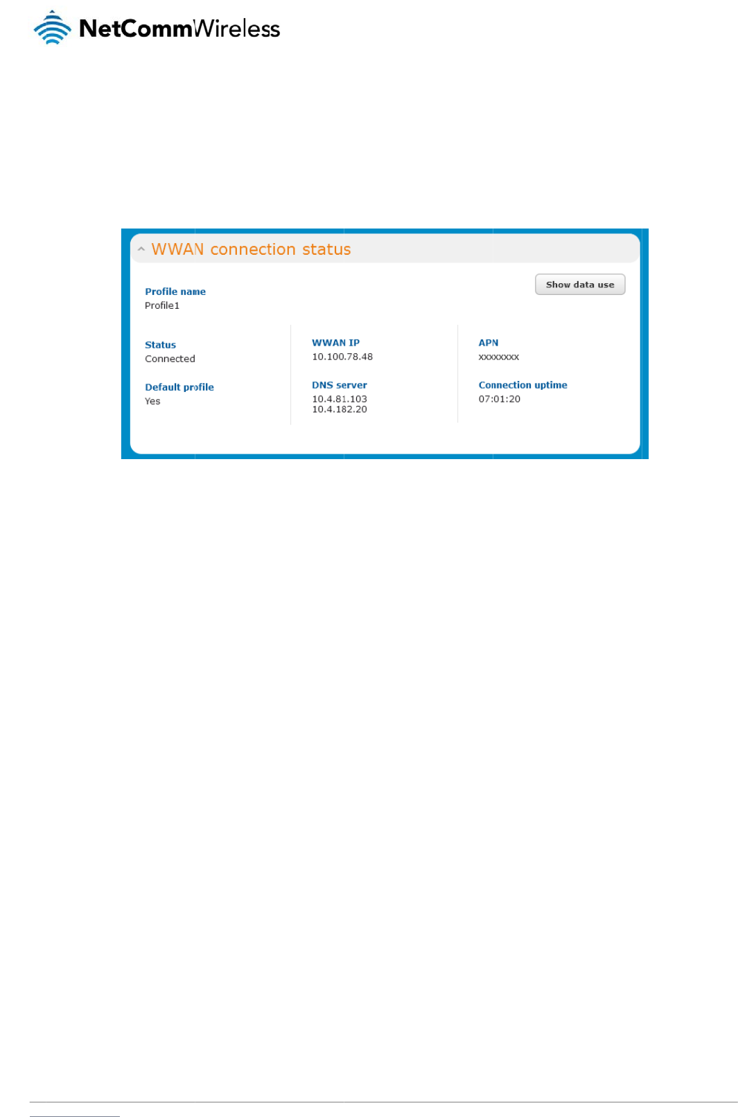
Profile name The name of the active profile.
Status The connection status of the active profile.
Default profile Indicates whether the current profile in use is the default profile.
WWAN IP The IP address assigned by the mobile broadband carrier network.
DNS server The primary and secondary DNS servers for the WWAN connection.
APN The Access Point Name currently in use.
Connection uptime The length of time of the current mobile connection session.
Advanced status
Mobile country code The Mobile Country Code (MCC) of the router.
Mobile network code The Mobile Network Code (MNC) of the router.
Signal quality (Ec/N0) A measurement of the portion of the received signal that is usable. This is the signal strength minus the signal noise level.
Received signal code power (RSCP) The power level of the signal on the current connection’s particular channel.
Power input mode Displays whether power is currently being sourced from the PoE Ethernet port or from the DC input jack (PoE available on NWL-12-01 only)
HSUPA category Displays the HSUPA category (1-9) for the current uplink
HSDPA category Displays the HSDPA category (1-8) for the current downlink.
SIM ICCID The Integrated Circuit Card Identifier of the SIM card used with the router, a unique number up to 19 digits in length.
Primary scrambling code (PSC) The Primary scrambling code for the current signal.
DC input voltage Displays the current voltage of the power input source provided via the DC Input jack
Location area code (LAC) The ID of the cell tower grouping the current signal is broadcasting from.

www.netcommwireless.com
IMSI
Cell ID
Channel number (UARF
C
C
N)
The Internation
a
A
unique code
t
The channel nu
m
a
l mobile subscriber identit
t
hat identifies the base sta
t
m
ber of the current 3G/2G
Table
t
y is a unique identifier of t
h
t
ion from within the locatio
n
connection.
1
1
- Status page ite
m
h
e user of a cellular netwo
r
n
area of the current mobil
e
m
details
N
e
r
k.
e
network signal.
etComm Wireless 3G
Light Industrial M2M
R
R
oute
r
23
24
NetComm Wireless 3G Light Industrial M2M Route
r
www.netcommwireless.com
Internet
The Internet section provides configuration options for Wireless WAN, LAN, Routing and VPN connectivity.
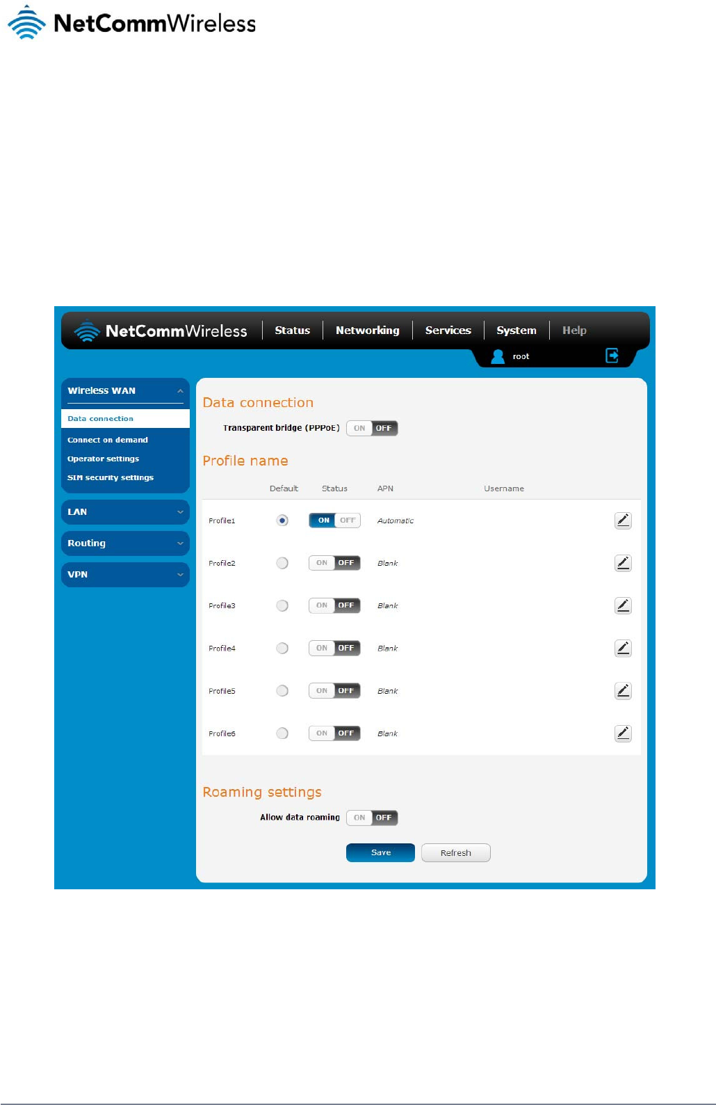
Data Connection
The data connection page allows you to configure and enable/disable the connection profile. To access this page, click on the Networking menu, and under the Wireless WAN menu, select the
Data Connection item.
Figure 18 – Data connection settings
www
C
o
The
bet
w
For
a
sele
c
con
f
ens
u
M
a
To
m
.netcommwireless.com
Data connection
Transparent Bridge (PPP
Profile name list
Default
Status
APN
Username
Roaming settings
Allow data roaming
o
nnecting
router supports the
c
w
een different conne
c
a
dvanced networkin
g
c
ting two profiles wit
h
f
lict and result in neit
h
u
re smooth operatio
n
a
nually c
o
m
anually configure a
1. Click the E
d
ITEM
P
oE)
to the mo
c
onfiguration of up t
o
c
tion settings.
g
purposes, you ma
y
h the same APN as t
h
er profile establishi
n
n
.
o
nfiguring
connection profile:
d
it button correspon
d
Toggles the tra
n
Sets the corres
p
Toggles the cor
The APN config
The username
u
When set to ON
router will deny
bile broa
d
o
six APN profiles; th
e
y
activate a maximu
m
his can cause only o
n
g a connection. We
a connec
t
d
ing to the Profile th
a
n
sparent bridge function o
n
p
onding profile to be the d
e
r
esponding profile on and
u
red for the correspondin
g
u
sed to log on to the corre
s
, the router will allow local
network access to data se
Table 1
2
d
band net
w
e
se profiles allow yo
u
m
of two profiles simu
ne profile to connec
t
recommend that the
t
ion profil
e
a
t you wish to modify
.
Figure 19
-
n
and off.
e
fault gateway for all outb
o
off. If your carrier support
s
g
profile.
s
ponding APN.
devices to access the Wir
e
e
rvices when roaming onto
2
- Data connection i
te
w
ork
u
to configure the se
t
ltaneously (depend
a
t
. Similarly, activatin
g
e
two active connecti
o
e
. The data connectio
- Data connection pr
o
DEFINITIO
N
o
und traffic except traffic f
o
s
it, two profiles may be tu
r
e
less WAN network when t
a foreign network. This se
t
te
m detail
s
t
tings that the router
w
a
nt on network supp
o
g
two profiles which
a
o
n profiles have diff
e
n profile settings pa
g
o
file setting
s
N
e
N
o
r which there are configur
e
n
ed on simultaneously.
h
e MachineLink 3G is roa
m
ting is ON by default.
w
ill use to connect to
rt). When activating
t
re both configured t
o
ring, manually confi
g
g
e is displayed.
etComm Wireless 3G
r
ed static route rules or pr
o
m
ing onto a foreign networ
o
the 2G/3G network
t
wo connection profi
l
o
automatically dete
r
g
ured APNs to avoid
Light Industrial M2M
R
file routing settings.
k
. When set to OFF, the
and switch easily
es, you should avoi
d
r
mine an APN can c
a
connection issues a
n
R
oute
r
25
d
a
use a
n
d
26
NetComm Wireless 3G Light Industrial M2M Route
r
www.netcommwireless.com
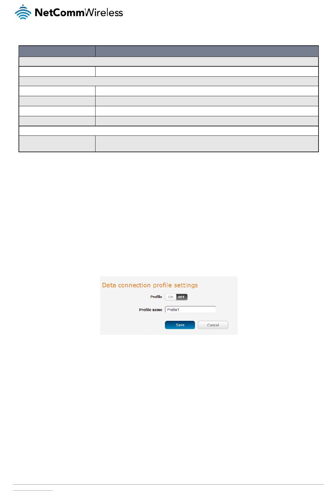
2. Click the Profile toggle key to turn the profile on. Additional settings appear.
Figure 20 - Data connection settings - Profile turned on
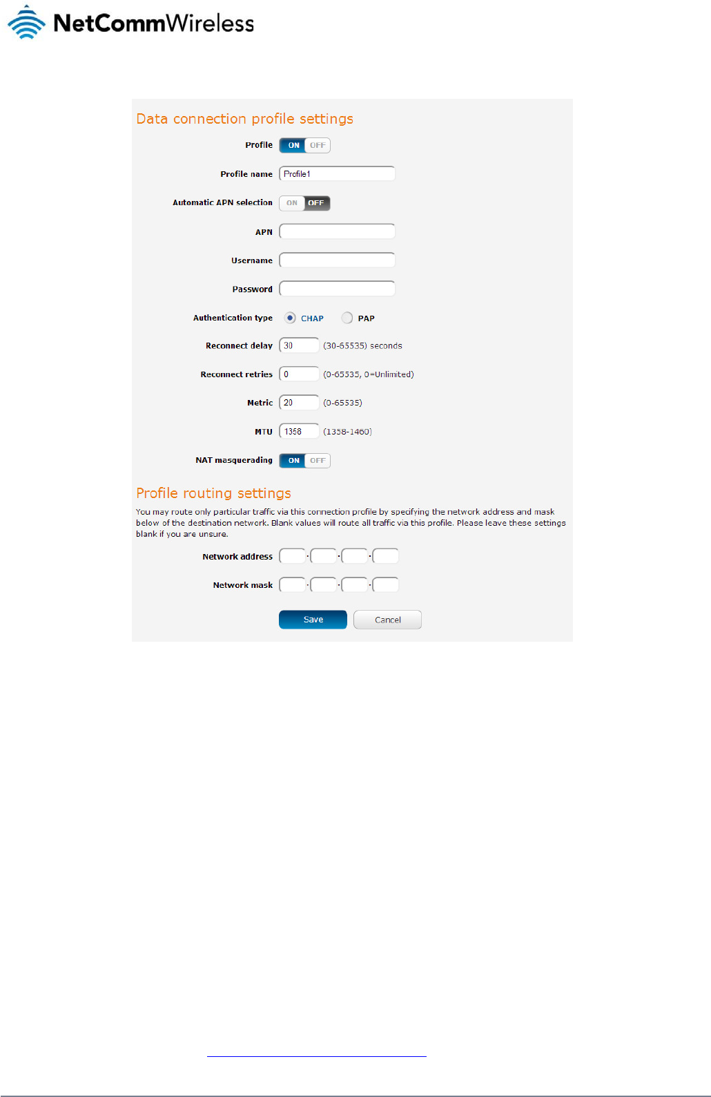
3. In the Profile name field, enter a name for the profile. This name is only used to identify the profile on the router.
4. Ensure that the Automatic APN selection toggle key is set to off. If it is not, click it to toggle it to the off position.
5. In the APN field, enter the APN Name (Access Point Name) and if required, use the Username and Password fields to enter your login credentials.
6. Next to Authentication type, select the either CHAP or PAP depending on the type of authentication used by your provider.
7. The Reconnect delay field specifies the number of seconds to wait between connection attempts. The default setting of 30 seconds is sufficient in most cases but you may modify it
to wait up to 65535 seconds if you wish.
8. The Reconnect retries field specifies the number of times to attempt to connect to the network if the router fails to establish a connection. It is set to 0 by default which causes the
router to attempt to reconnect indefinitely.
9. The Metric value is used by router to prioritise routes (if multiple are available) and is set to 20 by default. This value is sufficient in most cases but you may modify it if you are
aware of the effect your changes will have on the service.
10. The MTU field allows you to modify the Maximum Transmission Unit used on the connection. Do not change this unless instructed to by your carrier.
11. Use the NAT Masquerading toggle key to turn NAT Masquerading on or off. NAT masquerading, also known simply as NAT is a common routing feature which allows multiple LAN
devices to appear as a single WAN IP via network address translation. In this mode, the router modifies network traffic sent and received to inform remote computers on the internet
that packets originating from a machine behind the router actually originated from the WAN IP address of the router’s internal NAT IP address. This may be disabled if a framed
route configuration is required and local devices require WAN IP addresses.
12. For advanced networking such as using dual simultaneous PDP contexts, you may wish to configure a particular profile to route only certain traffic via that profile by configuring a
custom address and mask of traffic to send via that profile. To do this, in the Profile routing settings section, enter the Network address and Network mask of the remote network. If
you do not want to use this feature, or are unsure, please leave these fields blank, which will not designate any particular traffic to be routed via this profile. For more information on
configuring Profile routing settings, see the Setting a default gateway with two active connection profiles example.
www
C
o
Afte
r
con
n
usa
g
.netcommwireless.com
13. Click the S
a
o
nfirming
r
configuring the pa
c
n
ection, the WWAN
s
g
e button.
a
ve button when yo
u
a success
f
c
ket data session, an
d
s
ection is expanded
u
have finished enteri
f
ul conne
c
d
ensuring that it is
e
showing the details
o
ng the profile details
c
tion
e
nabled, click on the
o
f the connection an
d
Figure 21 - P
a
s
.
Status menu item at
d
the Status field dis
p
a
cket data connectio
n
the top of the page
t
p
lays Connected. To
n
status sectio
n
N
e
o return to the Statu
s
see details on the c
o
etComm Wireless 3G
s
page. When there i
s
o
nnected session, y
o
Light Industrial M2M
R
s
a mobile broadban
o
u can click the Sho
w
R
oute
r
27
d
w
data
28
Net
C
C
The
con
n
Wh
e
C
o
To
c
C
omm Wireless 3G Li
g
C
onnec
t
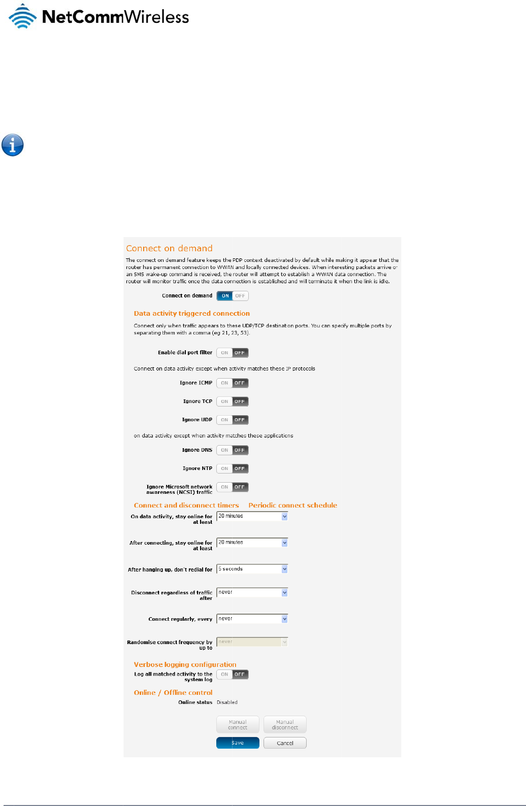
connect on demand
n
ection to the mobile
e
n the data connecti
o
Note: When i
o
nfigurin
g
onfigure Connect on
1. Click the N
2. On the Co
n
g
ht Industrial M2M Ro
u
t
on D
e
feature keeps the P
a
broadband network
o
n is established, the
nteresting packets a
g
Connect
demand:
etworking menu ite
m
n
nect on demand pa
g
u
te
r
e
mand
a
cket Data Protocol
(
. When a packet of i
n
router monitors traff
i
rrive, the recovery ti
m
on Dema
n
m
from the top menu
b
g
e, click the Connec
t
PDP) context deacti
v
n
terest arrives or an
S
c and terminates th
e
m
e for the wireless
W
n
d
b
ar.
t
on demand toggle
Figure 22 - Co
n
v
ated by default whil
S
MS wake-up comm
a
e
link when it is idle.
W
AN connection is a
p
key so that it is ON.
E
n
nect on demand con
f
e making it appea
r
t
o
a
nd is received, the
r
p
proximately 20-30 s
e
E
xtra options appea
r
f
iguration option
s
o
locally connected
d
r
outer attempts to es
t
e
conds.
. See the following s
u
d
evices that the rout
e
tablish a mobile bro
a
ub-sections for furth
e
www.netcommwire
l
e
r has a permanent
a
dband data connec
e
r instructions.
l
ess.com
tion.
www
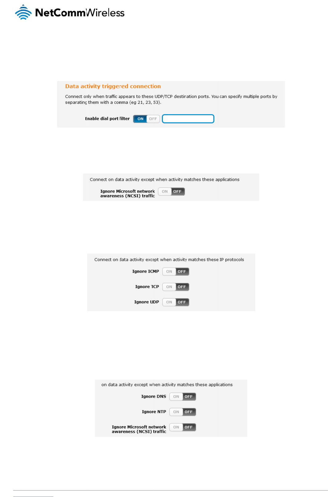
S
e
In s
o
this
f
host
You
to s
e
E
x
Dep
TCP
con
n
E
x
So
m
Net
w
that
.netcommwireless.com
e
tting the
r
o
me situations, you
m
f
eature, click Enable
on the specified po
r
can allow Microsoft
n
e
t it to ON.
x
cluding c
ending on your envi
r
, UDP or ICMP pack
e
n
ected device.
x
cluding c
m
e devices may gene
w
ork Time Protocol (
N
application type an
d
r
outer to
d
m
ay wish to have the
dial port filter and e
r
t(s) will trigger the c
o
n
etwork awareness (
c
ertain pa
c
r
onment, you might
p
e
ts. When any of the
s
c
ertain ap
p
e
rate general traffic a
s
N
TP) or Microsoft net
w
d
will not dial a conn
e
d
ial a conn
internet connection
d
nter the port numbe
r
o
nnection to dial. No
t
NCSI) traffic through
c
ket types
p
refer to exclude cert
s
e options are chec
k
p
lication t
y
s
a part of normal o
p
w
ork awareness (N
C
e
ction when this data
ection wh
e
d
isabled except at ti
m
or list of port numbe
t
e that when this fea
t
Figure 23 – Dial on
d
but if you prefer tha
t
Figure 24 -
D
from trig
g
ain types of traffic p
a
k
ed the router will no
t
Figure 25 – Di
a
y
pes from
p
eration which you m
a
C
SI) traffic from devic
type is received.
Figure 26 - Dial
o
en traffic
i
m
es when outbound
e
rs separated by co
m
t
ure is enabled, the
o
d
emand
- Data activi
ty
t they do not trigger
t
D
Ial on demand - Ign
o
g
ering th
e
a
ssing through the r
o
t
dial a connection w
ia
l
on demand - Exclu
d
triggerin
g
ay not want to trigge
c
es behind the router
o
n demand
- Excludin
g
i
s detecte
d
traffic to a particular
m
mas. When you sel
e
o
ptions to ignore spe
c
ty
triggered connectio
n
t
he connection, clic
k
o
re NCSI traffi
c
e
connecti
o
o
uter from triggering
t
h
en that type of outb
d
ing IP protocol
s
g
the con
n
r the data connectio
n
. When you check th
g
application type
s
N
e
d
on speci
external host’s port
o
e
ct this option, all out
b
c
ific packet types ar
e
n
the Ignore Microsoft
o
n to dial
t
he data connection.
o
und destined data
p
n
ection to
d
n
. You can set the ro
u
e
box for these optio
etComm Wireless 3G
i
fic ports
o
r range of ports is s
t
bound ICMP/TCP/U
D
e
not available.
t
network awareness
You can tell the rou
t
packet reaches the
r
d
ial
uter to ignore Domai
ns, it tells the router
t
Light Industrial M2M
R
e
nt to the router. To
u
D
P packets to any re
m
(NCSI) traffic toggl
e
er to ignore outboun
d
r
outer from a locally
n
Name System (DN
S
t
o ignore the reques
t
R
oute
r
29
u
se
m
ote
e
key
d
S
),
t
from
30
NetComm Wireless 3G Light Industrial M2M Route
r
www.netcommwireless.com
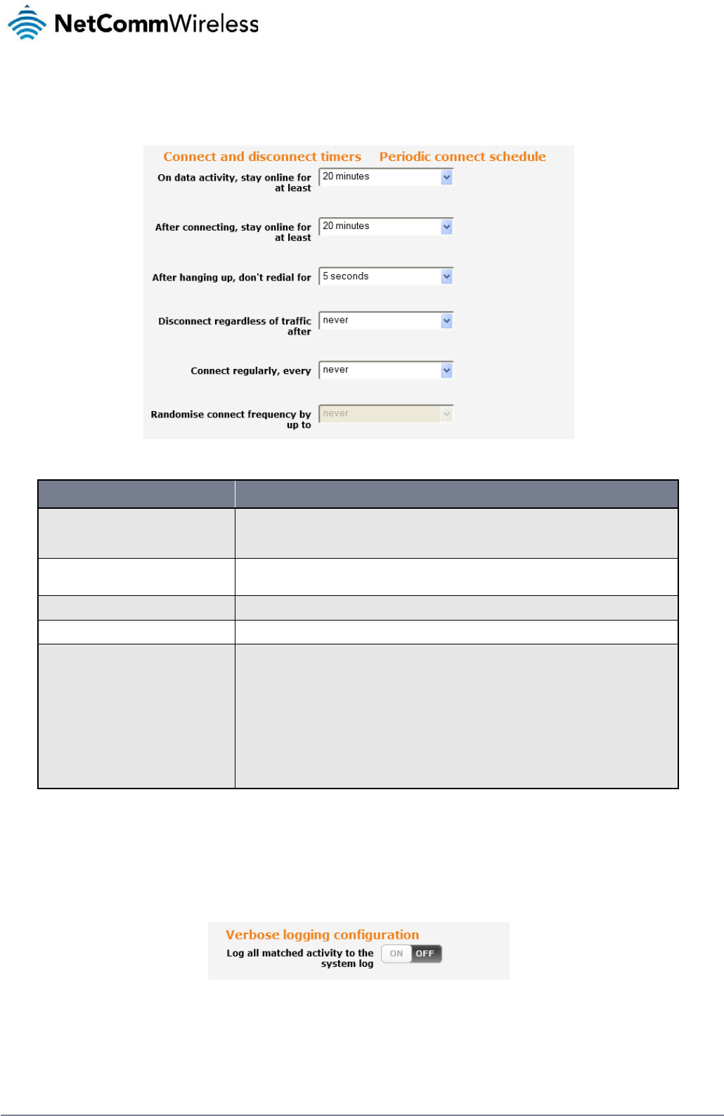
Setting timers for connection and disconnection
The router has a number of timer settings which let you determine when a connection is dialled and when it is disconnected.
Figure 27 – Dial on demand - Connect and disconnect timers
OPTION DESCRIPTION
On data activity, stay online for at least
When traffic as per the configured settings above appear, the router will either continue to stay online, or dial a connection and will not disconnect it
for the specified time period (min. 1 minute, max. 1 hour). This timer is continuously reset throughout the duration of a dial-up session, whenever
data activity is detected matching the rules above.
After connecting, stay online for at least This timer configures the router to not hang-up the connection for the specified time period after initially dialling the connection. This setting cannot
be less than the keep online period above. This timer affects the connection only once per dial up session, at the beginning of the session.
After hanging up, don’t redial for After a connection has been disconnected, you can tell the router to rest for a period of time before re-dialling.
Disconnect regardless of traffic after Forces the router to disconnect the connection regardless of the traffic passing through it. The default setting is never.
Connect regularly, every / Randomise connect frequency by
up to
If you want to have the router dial a connection at regular intervals, use Connect regularly, every to specify the interval between dials. Setting this to
never effectively disables this option.
The router also features the ability to randomise the time at which the first dial action is performed. This is useful in situations such as where you
have numerous routers in an area where a power outage has occurred. Setting a random dial time helps to reduce network congestion when all the
routers are powered on so they do not all try to connect simultaneously.
When it is set to at least 2 minutes, you are able to configure the router to randomise the time it begins to dial. The randomised dial timer only affects
the initial dial after the unit powers on or after the settings are saved. For example, if you configure the router to dial every 2 minutes with a
randomised dial time of 1 minute, the router will dial the initial connection at a time greater than 2 minutes, but less than 3 minutes. After the first dial,
the router will dial the connection exactly every 2 minutes.
Table 13 - Connect on demand - Connect and disconnect timers descriptions
Verbose mode
The router provides the option of logging all the data activity which matches the settings for the Dial on demand feature for advanced troubleshooting purposes. To enable the logging of the Dial
on demand feature, click the Enable verbose mode toggle key to switch it ON. See the System log section for more information.
Figure 28 – Dial on demand - Verbose logging configuration

www
M
a
The
r
whe
Wh
e
S
M
The
SM
S
.netcommwireless.com
a
nually c
o
r
e may be times whe
never necessary. Th
e
e
n you have finished
c
M
S Wake
u
router can also be
w
S
Wake up function.
o
nnecting
/
n you need to either
e
online status of the
c
onfiguring the opti
o
u
p
w
oken up by means
o
/
disconne
c
force a connection t
o
connection is displ
a
o
ns for the Dial on de
o
f an SMS message
u
c
ting
o
be made or force a
a
yed above the butto
n
Figure 29 - Di
a
m
and feature, click t
h
u
sing the SMS diagn
o
a
disconnection man
u
ns.
a
l on demand - Onlin
e
he Save button at th
e
o
stics feature by sen
u
ally. You can use th
e
e
/Offline control
e
bottom to save you
ding a zero byte cla
s
N
e
e
Manual connect an
r changes.
s
s 1 flash SMS. See t
h
etComm Wireless 3G
n
d Manual disconne
c
t
he Diagnostics secti
Light Industrial M2M
R
c
t buttons to do this
o
n for details on usi
n
R
oute
r
31
n
g the
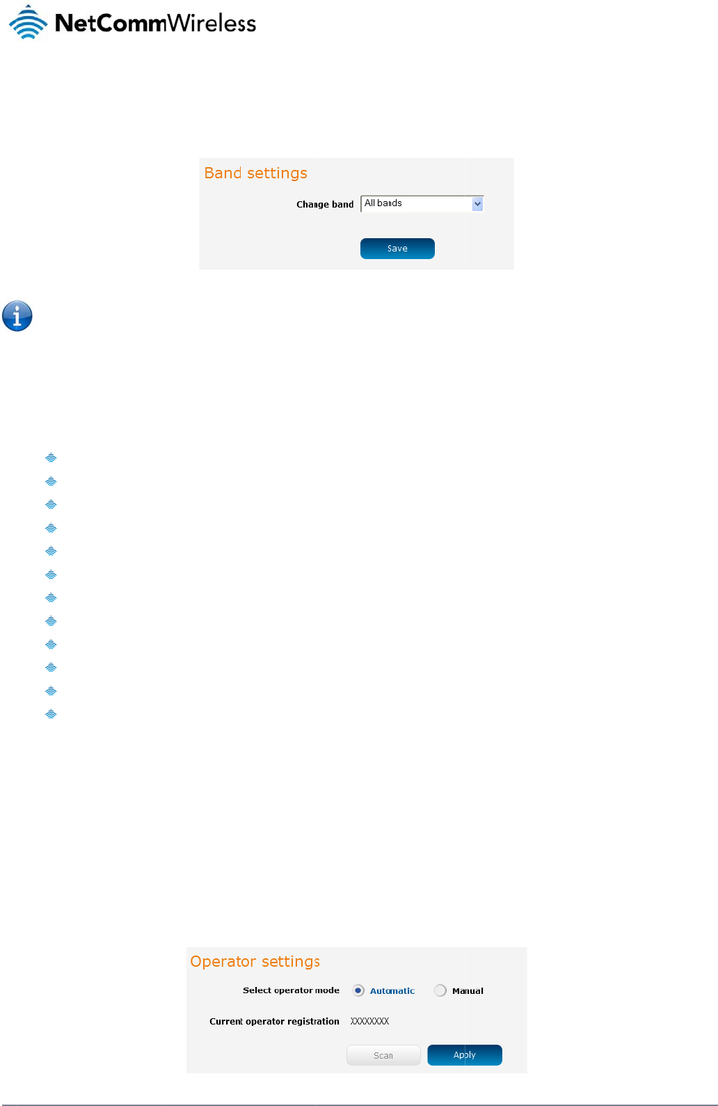
32
Net
C
O
The
You
con
n
Use
The
It is
forc
e
Wh
e
The
Clic
k
O
p
The
Sel
e
C
omm Wireless 3G Li
g
O
perat
o
Operator settings p
a
Note: In ord
e
already acti
v
may want to do this
i
n
ect on the network f
the Change band d
r
following band setti
n
All B
a
GSM
A
WCD
M
GSM
GSM
GSM
GSM
WCM
WCD
M
WCD
M
WCD
M
WCD
M
n
ot necessary to ch
a
e
d band selection is
e
n All bands is select
e
GSM All and the W
C
k
the Save button to
s
p
erator s
e
operator settings fe
a
e
ct operator mode fr
o
g
ht Industrial M2M Ro
u
o
r Setti
n
a
ge enables you to s
e
e
r to change the cell
u
v
e.
if you’re using the ro
u
f
requencies that suit
y
r
op down list to sele
c
n
gs options are avail
a
a
nds
All
M
A All
850
900
1800
1900
DA 850
M
A 900
M
A 800
M
A 1900
M
A 2100
a
nge the default setti
n
no longer available.
e
d, the router attem
p
C
DMA all options allo
w
s
ave and apply your
e
ttings
a
ture allows you perf
o
o
m automatic to Man
u
u
te
r
n
gs
e
lect which frequen
c
u
lar band settings, t
h
u
ter in a country with
y
our requirements.
c
t the band you wish
t
a
ble:
n
g of All bands in m
o
p
ts to find the most s
u
w
you to force the d
e
selection.
o
rm a scan of availa
b
u
al then click the sc
a
y band you will use
f
Fi
h
e data connection
m
multiple frequency
n
t
o use.
o
st cases. In fact, loc
u
itable band based
o
e
vice to lock to either
b
le networks, and to
o
a
n button. This opera
f
or your connection
a
F
igure
30 - Band setti
n
m
ust be disabled. W
h
n
etworks that may n
o
c
king to a particular
b
o
n the available net
w
r
2G networks only, o
o
ptionally lock to a p
a
tion can take a few
m
a
nd enables you to s
c
n
g
s
h
en you access this
p
o
t all support High S
p
b
and can cause con
n
w
orks for the inserted
r 3G networks only.
articular network ret
u
m
inutes and requires
c
an for available net
w
p
age, you are promp
t
p
eed Packet Access
n
ection difficulties if t
h
SIM card.
u
rned by the network
that the packet data
w
ork operators in yo
u
t
ed to disable the d
a
(HSPA). You can sel
he device is moved
t
k
scan. To scan for a
v
a
session be disconn
e
www.netcommwire
l
u
r area.
ta connection if it is
ect the router to onl
y
t
o a location where t
h
v
ailable networks, se
e
cted prior to scanni
l
ess.com
y
h
e
t the
ng.
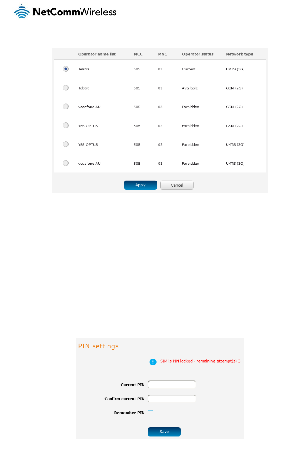
www
A lis
Sel
e
Wh
e
S
I
The
U
n
If th
e
stat
u
If yo
.netcommwireless.com
t of the detected 3G
ct the most appropri
e
n Select operator m
o
I
M sec
u
SIM security setting
s
n
locking
a
e
SIM card is locked,
u
s of the SIM at the t
o
u are not redirected
t
a) Click on th
e
service carriers in y
o
ate 3G service from
t
o
de is set to Automa
t
u
rity s
e
s
page can be used
f
a
PIN lock
e
,
you will receive a n
o
o
p of the page.
to the PIN settings p
a
e
Networking menu f
r
o
ur area is displayed
t
he list shown and cl
t
ic, the router selects
e
ttings
f
or authenticating SI
M
e
d SIM
o
tice when you acce
s
a
ge, to unlock the SI
r
om the top menu b
a
Fi
g
.
Figu
re
i
ck Apply.
the most appropriat
e
M
cards that have b
e
s
s the Status page a
f
M:
a
r, and then click SI
M
Figure 33 - S
I
g
ure
31 - Operator se
tt
re
32 - Detected oper
a
e operator based on
e
en configured with
a
f
ter which you will b
e
M
security settings.
SI
M security settings
-
S
tt
ing
s
a
tor lis
t
the inserted SIM ca
r
a
security PIN.
e
directed to the PIN
S
IM PIN locked
N
e
r
d. This is the default
s
ettings page to ent
e
etComm Wireless 3G
t
option and is suffici
e
e
r the PIN. The PIN
s
Light Industrial M2M
R
e
nt for most users.
ettings page lists th
e
R
oute
r
33
e
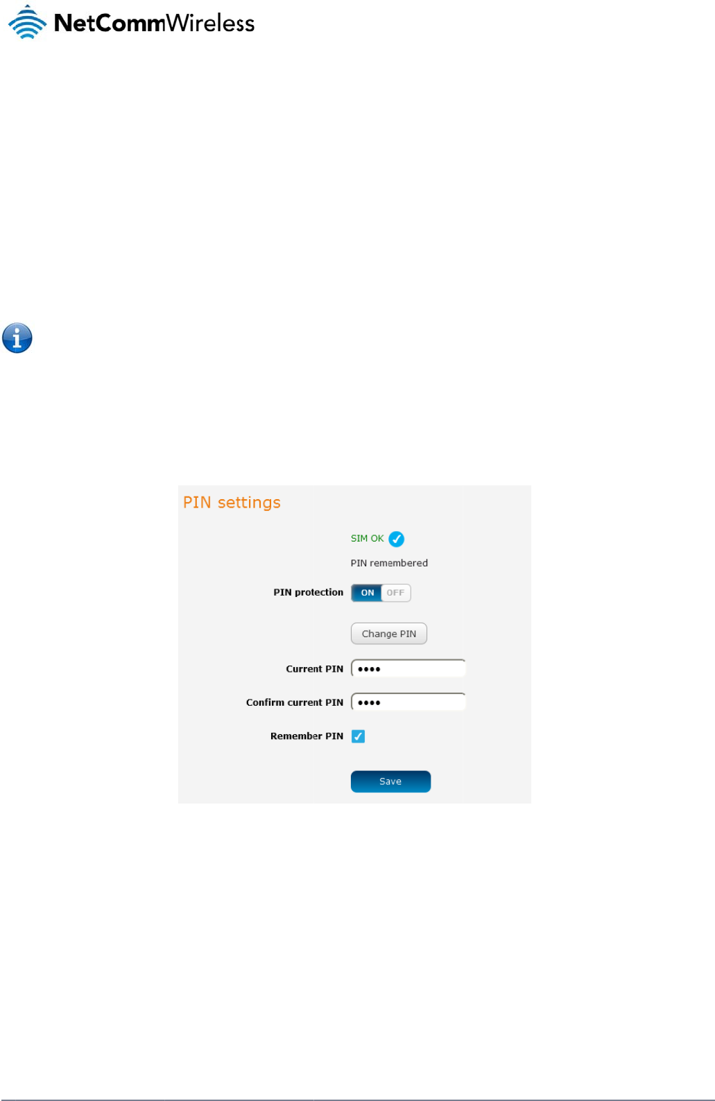
34
Net
C
E
n
The
C
omm Wireless 3G Li
g
b) Enter the P
c) If you are
p
SIM each ti
connect to
When this
f
PIN, the ro
u
When this
f
unattende
d
Note: Selec
t
d) Click the S
a
n
abling/D
i
security PIN protecti
g
ht Industrial M2M Ro
u
IN in the Current PI
N
p
lacing the router in
a
i
me the SIM asks for
the cellular service.
f
eature is enabled, t
h
u
ter decrypts the PI
N
f
eature is disabled a
n
d
, this is not desirabl
e
t
Remember PIN if y
o
a
ve button. If succe
s
i
sabling S
I
on can be turned on
u
te
r
N
field and then ente
r
a
remote, unattende
d
it (usually at power
u
h
e PIN you enter whe
N
and automatically
s
n
d the SIM is PIN loc
e
.
o
u do not want to en
t
s
sful, the router displ
a
I
M PIN pr
o
or off using the PIN
r
it again in the Confi
r
d
location, you may
w
u
p). This enables the
n setting the Reme
m
ends it to the SIM wi
t
ked and the PIN mu
s
t
e
r
the PIN code eac
h
a
ys the following scr
e
o
tection
protection toggle ke
y
F
r
m current PIN field
t
w
ish to check the Re
m
SIM to be PIN locke
m
ber PIN feature is e
n
t
hout user interventi
o
s
t be manually enter
e
h time the SIM is ins
e
e
en:
y
.
F
igure
34 - PIN Setti
ng
t
o confirm the PIN.
m
ember PIN option.
T
d
(to prevent unauth
o
n
crypted and stored
o
n.
e
d via the router‘s co
e
rted.
ngs
T
his feature allows th
o
rised re-use of the
S
locally on the router.
n
figuration interface.
h
e router to automati
c
S
IM elsewhere), whil
e
The next time the SI
.
In situations where
t
www.netcommwire
l
c
ally send the PIN to
e
still allowing the ro
u
M asks the router fo
r
t
he router will be
l
ess.com
the
u
ter to
r
the
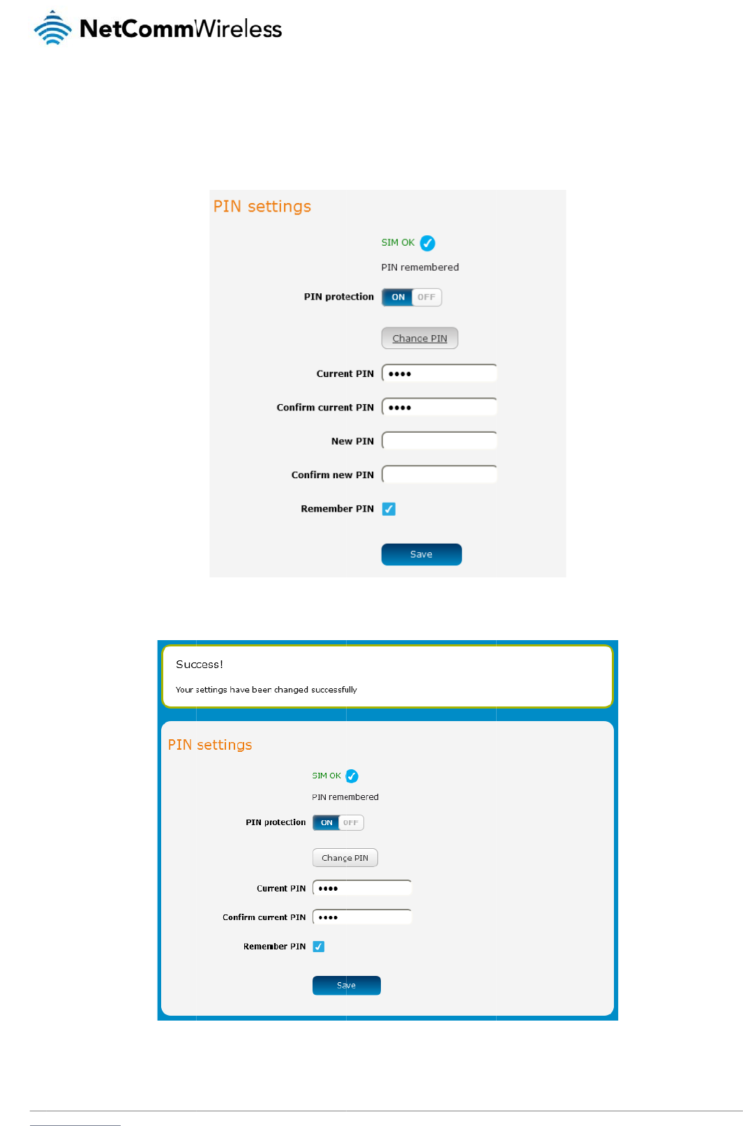
www
C
h
If yo
Con
f
Wh
e
.netcommwireless.com
h
anging t
h
u would like to chan
g
f
irm new PIN fields
a
e
n the PIN has been
c
h
e SIM PI
N
g
e the PIN, click the
C
a
nd click the Save b
u
c
hanged successfull
N
code
C
hange PIN button
a
u
tton.
y, the following scre
e
a
nd enter the current
Figure
3
e
n is displayed:
Figure 36 - SIM
s
t
PIN into the Current
35
- PIN settings - C
ha
s
ecurity settings
– PI
N
PIN and Confirm cu
ha
nge PIN
N
unlock successful
N
e
rrent PIN fields, then
etComm Wireless 3G
n
enter the desired P
I
Light Industrial M2M
R
N into the New PIN
a
R
oute
r
35
a
nd
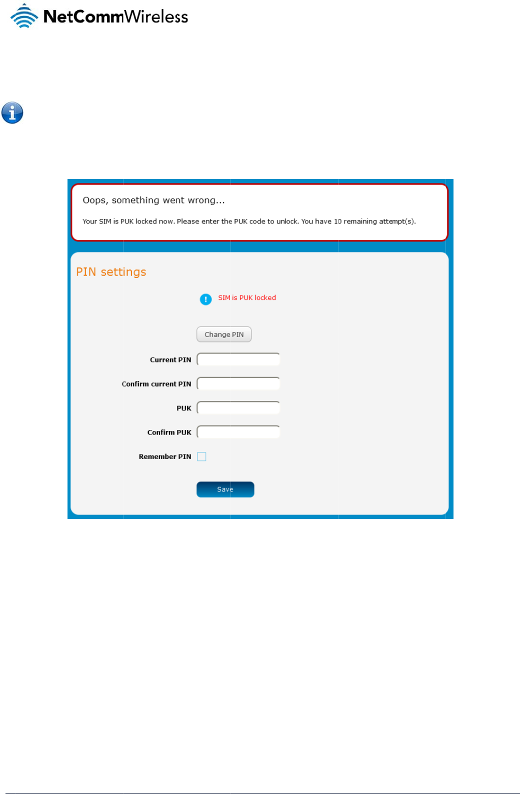
36
Net
C
U
n
Afte
r
You
Clic
k
C
omm Wireless 3G Li
g
n
locking
a
r
three incorrect atte
m
Note: To obta
will be issued a PU
K
k
the Save button w
h
g
ht Industrial M2M Ro
u
a
PUK lock
e
m
pts at entering the
in the PUK unlock c
o
K
to enable you to un
l
h
en you have finishe
d
u
te
r
e
d SIM
PIN, the SIM card b
e
o
de, you must conta
c
l
ock the SIM and ent
e
d
entering the new PI
e
comes PUK (Person
c
t Vodafone.
e
r a new PIN. Enter t
N and PUK codes.
Figure 3
7
n
al Unblocking Key) l
t
he new PIN and PU
K
7
- SIM security - SIM
P
ocked and you are r
e
K
codes.
P
UK locked
e
quested to enter a
P
P
UK code to unlock i
www.netcommwire
l
t.
l
ess.com
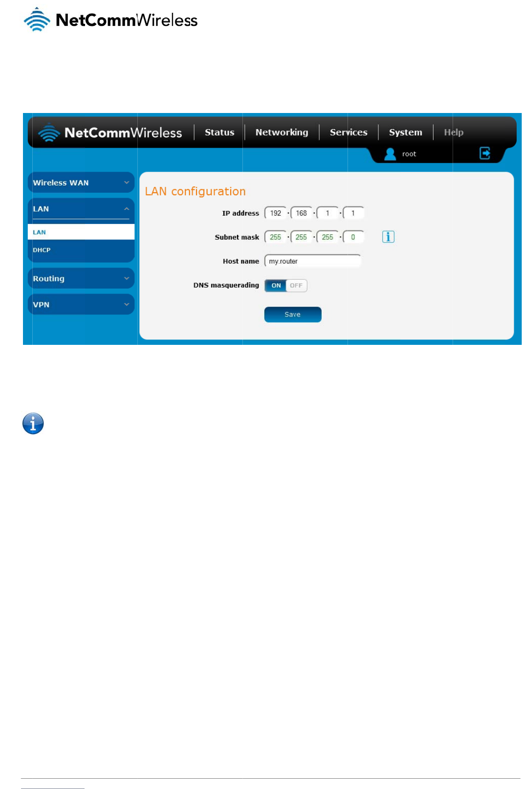
www
L
A
L
A
The
The
butt
o
D
N
DN
S
serv
With
dow
With
ups
t
You
the
D
In m
.netcommwireless.com
A
N
A
N config
u
LAN configuration p
a
default IP of the Eth
e
o
n.
Note: If you
c
N
S masquera
d
S
masquerading allo
w
er without needing t
o
DNS masquerading
nstream clients then
DNS masquerading
t
ream DNS servers
w
may also override th
D
HCP server assign
s
ost cases, it is not n
e
u
ration
a
ge is used to confi
g
e
rnet port is 192.168.
c
hange the IP addre
d
ing
w
s the router to prox
y
o
know the dynamic
a
ON, the DHCP serv
e
send DNS requests
OFF, the DHCP ser
v
w
ithout being proxied
e DNS Masqueradin
s
downstream devic
e
e
cessary to disable
D
g
ure the LAN setting
s
1.1 with subnet mas
k
ss, remember to reb
o
y
DNS requests from
a
lly assigned cellular
e
r embedded in the
3
to the 3G Light Indu
s
v
er hands out the up
by the 3G Light Ind
u
g option by specifyi
n
e
s the manually confi
g
D
NS masquerading
b
s
of the router and to
Figure
3
k
255.255.255.0. To
c
o
ot the router and e
n
LAN clients to dyna
m
network DNS server
s
3
G Light Industrial M
s
trial M2M router whi
s
tream DNS server I
P
u
strial M2M router.
n
g custom DNS Serv
e
g
ured addresses an
d
b
ut if you need to, cli
c
enable or disable D
N
38
– LAN configurati
on
c
hange the IP addre
n
ter the new IP addr
e
m
ically assigned DN
S
s
.
M
2M router hands ou
t
ch proxies them to t
h
P
addresses to dow
n
e
r IP addresses in th
d
the DNS Masquer
a
c
k the DNS masque
r
N
S Masquerading.
on
setting
s
s
s or Subnet mask,
e
e
ss into your browser
S
servers. When ena
its own IP address (
h
e upstream DNS se
r
n
stream clients direc
t
e DHCP Server conf
i
a
ding option is ignor
e
r
ading toggle key to
t
N
e
e
nter the new IP Add
r
address ba
r
.
b
led, clients on the r
o
e
.g. 192.168.1.1) as
r
vers.
t
ly, so that downstre
a
guration mentioned i
e
d.
urn it OFF and then
c
etComm Wireless 3G
ress and/or Subnet
m
r
outer’s LAN can the
n
the DNS serve
r
add
r
a
m clients send DNS
in the next section o
f
click the Save butto
n
Light Industrial M2M
R
m
ask and click the S
a
n
use the router as a
r
ess to LAN clients.
T
requests directly to
f
this guide. In this c
a
n
.
R
oute
r
37
a
ve
DNS
T
he
the
a
se
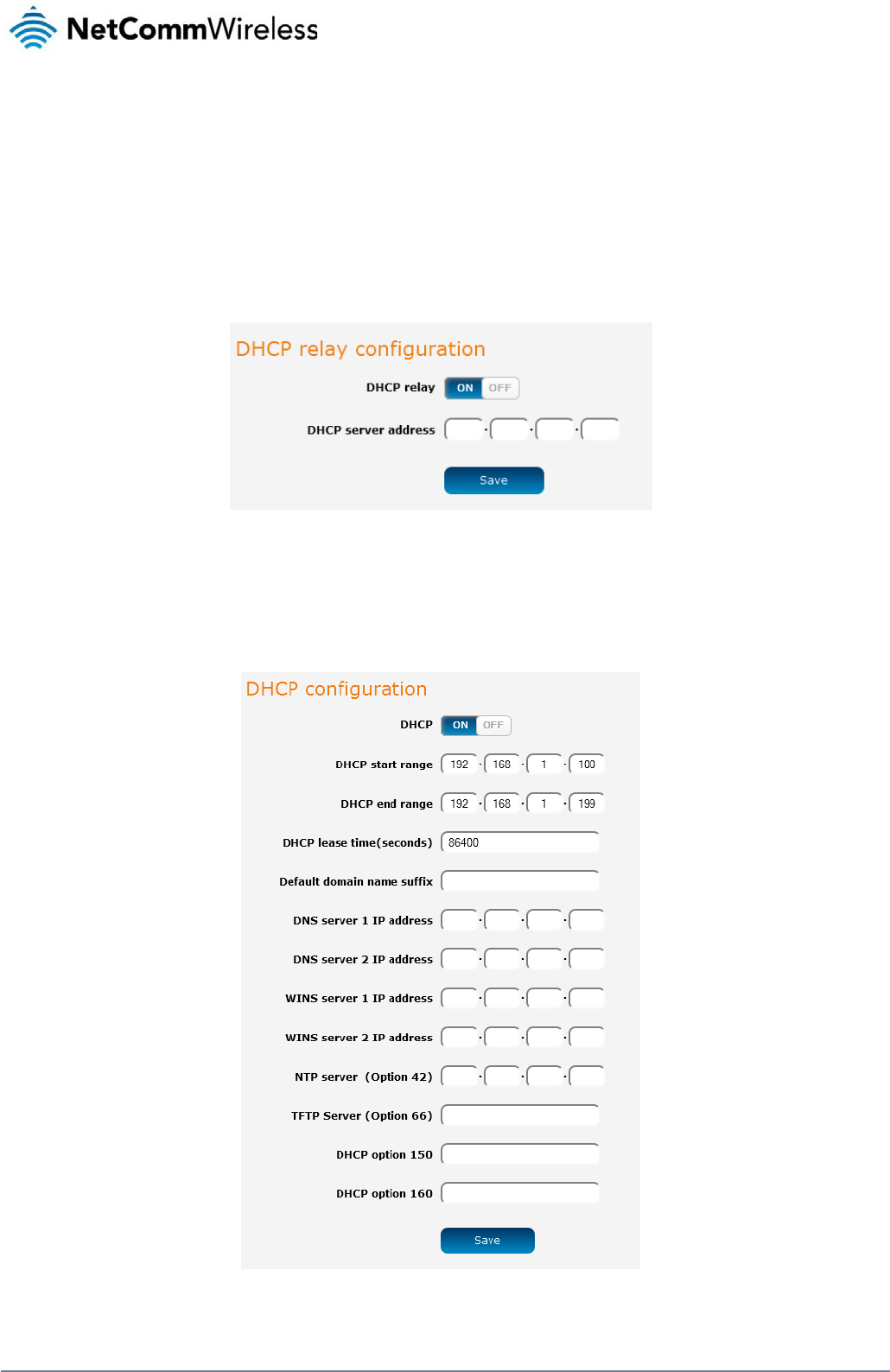
38
NetComm Wireless 3G Light Industrial M2M Route
r
www.netcommwireless.com
DHCP
The DHCP page is used to adjust the settings used by the router’s built in DHPC Server which assigns IP addresses to locally connected devices.
DHCP relay configuration
In advanced networks configurations where the 3G Light Industrial M2M Router should not be responsible for DHCP assignment, but instead an existing DHCP server is located on the Wireless
WAN connection, the clients behind the 3G Light Industrial M2M Router are able to communicate with the DHCP server when DHCP relay is enabled. This enables the 3G Light Industrial M2M
Router to accept client broadcast messages and to forward them onto another subnet.
To configure the router to act as a DHCP relay agent click the DHCP relay toggle key to turn it ON and enter the DHCP server address into the DHCP server address field. DHCP relay is
disabled by default.
Figure 39 – DHCP relay configuration
DHCP configuration
You can manually set the start and end address range to be used to automatically assign addresses within, the lease time of the assigned address, the default domain name suffix, primary and
secondary DNS server, the primary and secondary WINS server, as well as the advanced DHCP settings such as NTP, TFTP and Option 150/Option 160 (VoIP options).
Figure 40 - DHCP configuration
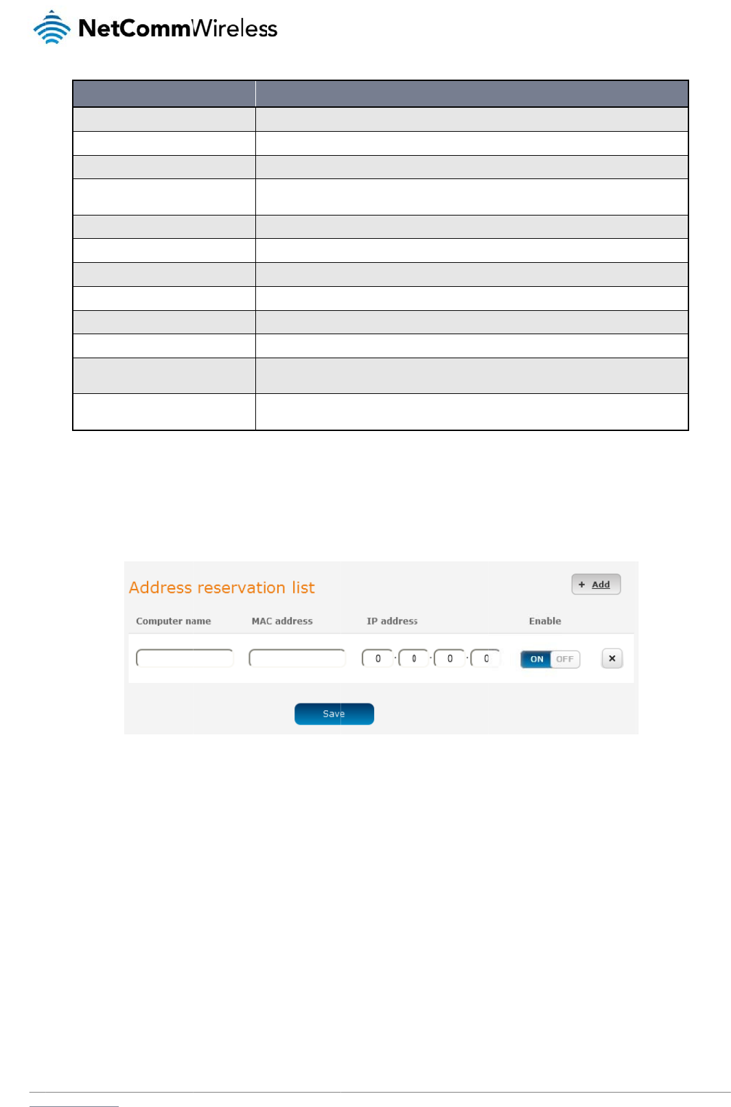
www
Ent
e
Ad
DH
C
To
a
.netcommwireless.com
DHCP start ra
DHCP end ra
n
DHCP lease ti
Default domai
DNS server 1
DNS server 2
WINS server 1
WINS server
2
NTP server (
O
TFTP Server (
O
DHCP option
DHCP option
e
r the desired DHCP
d
dress reserv
a
C
P clients are dynam
dd a device to the a
d
1. Click the +
A
2. In the Com
3. In the MA
C
4. In the IP A
d
5. If the Enab
l
6. Click the S
a
OPTION
nge
n
ge
me (seconds)
n name suffix
IP address
IP address
1
IP address
2
IP address
O
ption 42)
O
ption 66)
150
160
options and click th
e
a
tion list
ically assigned an I
P
d
dress reservation li
s
A
dd button.
puter Name field ent
C
Address field, ente
r
d
dress fields, enter t
h
le toggle key is not s
a
ve button to save t
h
S
S
T
h
S
w
S
S
S
S
S
S
T
h
r
e
T
h
s
e
e
Save button.
P
address as they co
n
s
t:
er a name for the de
v
r
the device’s MAC a
d
h
e IP address that y
o
et to ON, click it to s
w
h
e settings.
e
ts the first IP address of t
h
e
ts the last IP address of t
h
h
e length of time in secon
d
p
ecifies the default domai
n
w
ithout typing the full doma
i
p
ecifies the primary DNS (
p
ecifies the secondary DN
p
ecifies the primary WINS
p
ecifies the secondary WI
N
p
ecifies the IP address of
t
p
ecifies the TFTP (Trivial F
h
is is used to configure Ci
s
e
quest to the DHCP server
h
is is used to configure Po
e
nds a request to the DHC
n
nect, but you can r
e
Figure 41
–
v
ice.
d
dress.
o
u wish to reserve fo
r
w
itch it to the ON po
s
he DHCP range
h
e DHCP range
d
s that DHCP allocated IP
n
name suffix for the DHC
P
in name server1.domain.c
o
(
Domain Name System) se
N
S (Domain Name System)
(Windows Internet Name
S
N
S (Windows Internet Na
m
t
he NTP (Network Time Pr
o
F
ile Transfer Protocol) serv
e
s
co IP phones. When a Ci
s
to obtain this information.
o
lycom IP phones. When a
C
P server to obtain this info
e
serve an address fo
– DHCP –
A
ddress re
s
r
the device.
sition.
DESCRIPTI
O
a
ddresses are valid
P
clients. A domain name
s
o
m
rver’s IP address.
server’s IP address.
S
ervice) server IP address
m
e Service) server IP addr
e
o
tocol) server
e
r
s
co IP phone starts, if it is
n
Specify the string which w
Polycom IP phone starts, i
f
rmation. Specify the string
r a particular device
s
ervation lis
t
N
e
O
N
uffix enables users to acc
e
e
ss
n
ot pre-configured with the
ll be sent as a reply to the
f
it is not pre-configured wi
t
which will be sent as a re
p
using the address r
e
etComm Wireless 3G
e
ss a local server, for exa
m
e
IP address and TFTP add
option 150 request.
i
th the IP address and TFT
p
ly to the option 160 reque
e
servation list.
Light Industrial M2M
R
m
ple, server1,
ress, it sends a
P
address, it
st.
R
oute
r
39

40
NetComm Wireless 3G Light Industrial M2M Route
r
www.netcommwireless.com
Dynamic DHCP client list
The Dynamic DHCP client list displays a list of the DHCP clients. If you want to reserve the current IP address for future use, click the Clone button and the details will be copied to the address
reservation list fields. Remember to click the Save button under the Address reservation list section to confirm the configuration.
Figure 42 - Dynamic DHCP client list
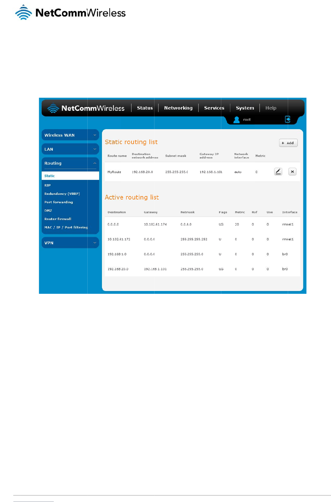
www
R
St
a
Stati
con
f
stati
c
So
m
Ad
To
a
.netcommwireless.com
outing
a
tic
c routing is the alter
n
f
iguring the routers i
n
c
route, the route wil
l
m
e routes are added
b
d
ding Static R
o
dd a new route to th
e
1. In the Rout
2. From the N
3. In the Dest
i
4. In the IP s
u
5. In the Gate
6. In the Metr
i
priority, se
t
7. Click the S
a
n
ative to dynamic ro
u
n
your network with a
l
be broken.
b
y default by the rou
t
o
utes
e
static routing list, c
e name field, type a
etwork interface dro
p
i
nation IP address fi
e
u
bnet mask field, ent
e
way IP address field
i
c field enter the met
r
t
it to 0.
a
ve button to save y
o
u
ting used in more c
o
ll the information ne
c
t
er on initialization s
u
lick the +Add button
.
name for the route s
o
p
down list, select th
e
e
ld, enter the IP add
r
e
r the subnet mask
o
, enter the IP addre
s
r
ic for the route. The
o
ur settings.
o
mplex network sce
n
c
essary to allow the
p
Fi
g
u
ch as the Ethernet s
u
.
The Static routes p
a
o
that it can be ident
i
e
interface for which
r
ess of the destinatio
o
f the route.
s of the gateway tha
t
metric value is used
n
arios and is used to
p
ackets to be forwar
d
g
ure
43 - Static routi
ng
ubnet route for routi
n
a
ge appears.
ified in the static rou
t
you would like to cr
e
n of the route.
t will facilitate the ro
u
by the router to prio
r
facilitate communic
a
d
ed to the correct de
ng
lis
t
n
g to a device on the
t
ing list.
e
ate a static route.
u
te.
r
itise routes. The low
e
N
e
a
tion between device
s
tination. If you chan
Ethernet subnet.
e
r the value, the high
etComm Wireless 3G
e
s on different netwo
r
n
ge the IP address o
f
h
er the priority. To gi
v
Light Industrial M2M
R
r
ks. Static routing inv
f
one of the devices i
n
v
e the route the high
e
R
oute
r
41
olves
n
the
e
st
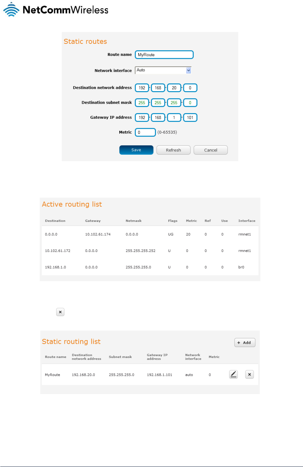
42
NetComm Wireless 3G Light Industrial M2M Route
r
www.netcommwireless.com
Figure 44 - Adding a static route
Active routing list
Static routes are displayed in the Active routing list.
Figure 45 - Active routing list
Deleting static routes
From the static routing list, click the icon to the right of the entry you wish to delete.
Figure 46 - Deleting a static route
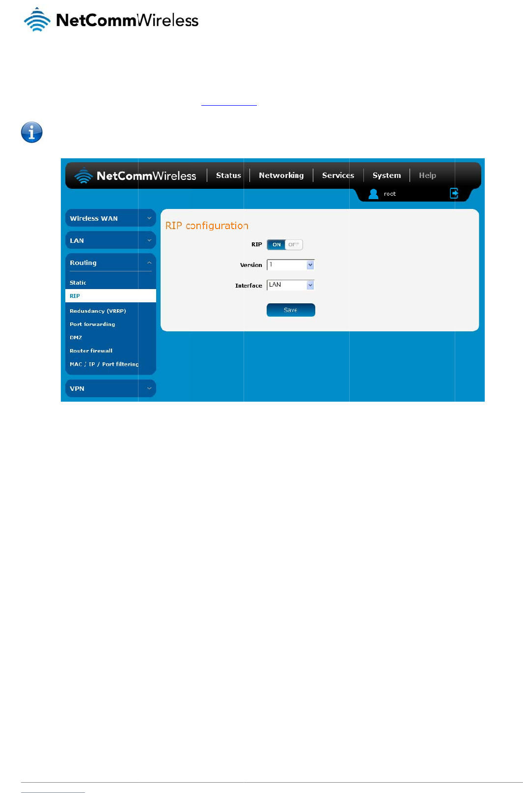
www
RI
RIP
for t
h
rout
e
To
e
.netcommwireless.com
P
(
Routing Information
h
e router’s Ethernet
s
e
s must be added m
Note: Some
r
nable Routing Infor
m
1. Click the R
2. Using the
V
3. Select the i
4. Click the S
a
Protocol) is used fo
r
s
ubnet could be adv
e
anually according to
r
outers will ignore RI
P
m
ation Protocol (RIP)
IP toggle key to swit
c
V
ersion drop down li
s
nterface for which y
o
a
ve button to confir
m
r
advertising routes t
o
e
rtised to a
r
outer on
your requirements.
S
P
.
c
h it to the ON positi
o
s
t, select the version
o
u want RIP to apply.
m
your settings.
o
other routers. Thus
the PPP interface si
d
S
ee Adding Static R
o
Fi
g
o
n.
of RIP that you woul
d
You can choose th
e
all the routes in the
r
d
e so that a router o
n
o
utes.
g
ure
47 - RIP configu
ra
d
like to use.
e
LAN interface, the
W
r
outer’s routing table
n
this network will kn
o
ra
tio
n
W
WAN interface or
B
N
e
will be advertised to
o
w how to route to a
d
oth.
etComm Wireless 3G
other nearby router
s
device on the router
’
Light Industrial M2M
R
s
. For example, the r
o
s Ethernet subnet. S
t
R
oute
r
43
o
ute
t
atic
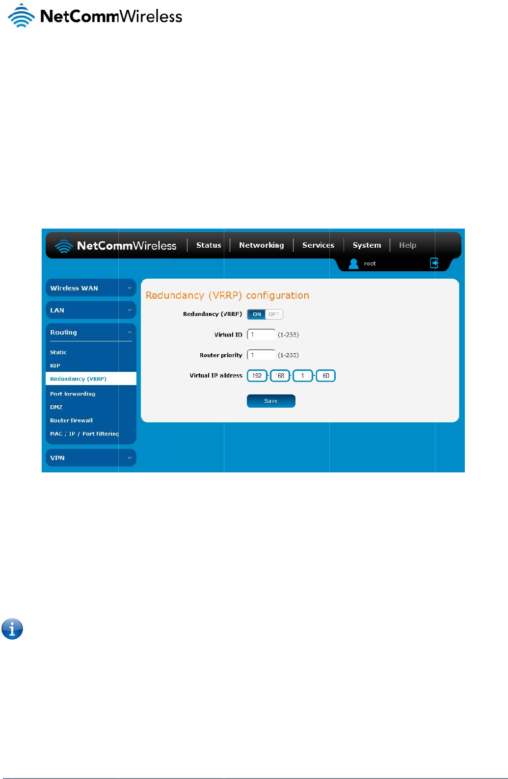
44
Net
C
R
e
Virt
u
incr
e
phy
s
routi
of th
Mas
A vi
r
This
To
c
C
omm Wireless 3G Li
g
e
dundanc
y
u
al Router Redundan
c
e
ased reliability is ac
s
ical router. Two or
m
ng the data on beha
e virtual router is cal
ter routers have a pr
i
r
tual router must use
address is used by
o
onfigure VRRP, conf
i
1. Click the R
2. In the Virtu
a
3. In the Rout
4. The Virtual
5. Click the S
a
Note: Config
u
on a comma
n
arp –d
g
ht Industrial M2M Ro
u
y
(VRRP)
c
c
y Protocol (VRRP) i
s
c
hieved by advertisin
g
m
ore physical routers
lf of the virtual route
r
led the master route
r
iority of 255 and bac
00-00-5E-00-01-XX
a
o
nly one physical ro
u
igure multiple devic
e
edundancy (VRRP)
t
a
l ID field, enter an I
D
er priority field, ente
r
IP address field is u
s
a
ve button to save t
h
u
ring VRRP change
s
n
d prompt type:
<ip addre
s
u
te
r
c
onfigurat
i
s
a non-proprietary r
e
g
a “virtual router” (
a
are then configured
r
fails, an arrangeme
n
r
.
kup router(s) can ha
v
a
s its (MAC) addres
s
u
ter at a time, and is
e
s as follows and co
n
t
oggle key to activat
e
D
between 1 and 25
5
r
a value for the prior
s
ed to specify the V
R
h
e new settings.
s
the MAC address o
f
s
s> (i.e. arp
i
on
e
dundancy protocol
n abstract represent
to stand for the virtu
n
t is made for anoth
e
v
e a priority betwee
n
s
. The last byte of the
the only way that oth
Fig
u
n
nect them all via an
e
VRRP.
5
. This is the VRRP I
D
i
ty – a higher value i
s
R
RP IP address – thi
s
f
the Ethernet port a
n
–d 192.16
8
designed to increas
e
t
ation of master and
b
al router, with only o
n
e
r physical router to
a
n
1 and 254.
e
address (XX) is the
h
er physical routers
c
u
re
48 - VRRP config
ur
Ethernet network sw
i
D
which is different f
o
s
a higher priority.
s
is the virtual IP add
n
d therefore if you w
a
8
.1.1) to clear
e
the availability of th
b
ackup routers actin
g
n
e doing the actual r
a
utomatically replac
e
Virtual Router Identif
c
an identify the mast
e
ur
atio
n
i
tch to downstream
d
o
r each virtual router
ress that both virtual
a
nt to resume with th
e
the arp cache.(old
M
e default gateway s
e
g
as a group) as a d
e
o
uting at any given ti
it. The physical rout
e
i
er (VRID), which is
d
e
r router within a virt
u
d
evices.
on the network.
routers share.
e
web configuration
y
M
AC address).
e
rvicing hosts on the
e
fault gateway to th
e
ime. If the current p
h
t
er that is currently fo
d
ifferent for each virt
u
u
al router.
y
ou must use the ne
w
www.netcommwire
l
same subnet. This
e
host(s) instead of o
n
h
ysical router that is
rwarding data on be
h
u
al router in the netw
o
w
IP address (VRRP
I
l
ess.com
n
e
h
alf
o
rk.
I
P) or
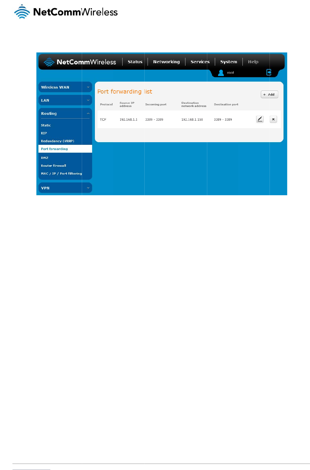
www
P
o
The
The
Ad
To
c
.netcommwireless.com
o
rt Forwar
d
Port forwarding list i
s
purpose of the port
f
d
ding a port f
o
reate a new port for
w
1. Click the +
A
2. Use the Pr
o
3. In the Sour
4. The Sourc
e
numbers b
y
(To) field.
5. In the Dest
i
6. The Destin
a
then the d
e
port range.
7. Click the S
a
ding
s
used to configure t
h
f
orwarding feature is
o
rwarding ru
l
w
arding rule:
A
dd button. The port
o
tocol drop down list
r
ce IP Address field,
e
e
Port Range (From)
y
entering the first in
i
nation network adre
s
a
tion Port Range (F
r
e
stination port may b
e
a
ve button to confir
m
h
e Network Address
to allow mapping of
l
e
forwarding settings
to select the type of
e
nter a “friendly” ad
d
and (To) fields are
u
the range in the (Fr
o
s
s field, enter the IP
a
r
om) and (To) fields
a
e
configured to any
p
m
your settings.
Translation (NAT) ru
l
Fig
u
inbound requests to
s
creen is displayed.
protocol you want t
o
d
ress that is allowed
u
sed to specify the p
o
o
m) field and the last
a
ddress of the client
a
re used to specify t
h
p
ort. If the Source po
les currently in effec
t
u
re
49 – Port forward
in
a specific port on th
o
use for the rule. Th
e
to access the router
ort(s) on the source
s
in the range in the (
T
to which the traffic
s
h
e port(s) on the de
s
o
rt range specifies a
r
t
on the router.
in
g lis
t
e
WAN IP address t
o
e
protocols selection
s
or a wildcard IP add
s
ide that are to be fo
T
o) field. To forward
s
hould be forwarded.
tination side that are
r
ange of port numbe
r
N
e
o
a device connecte
d
s
available are TCP,
ress (0.0.0.0) that all
r
warded. This allows
a
single port, enter t
h
to be forwarded. If t
h
r
s then the Destinati
o
etComm Wireless 3G
d
on the Ethernet int
e
UDP and All.
l
ows all IP addresse
s
s
you to send a rang
e
h
e po
r
t in the (From)
he Source port rang
e
o
n port range must b
Light Industrial M2M
R
e
rface.
s
to access the route
r
e
of consecutive port
field and repeat it in
e
specifies a single
p
e
the same as the S
o
R
oute
r
45
r
.
the
p
ort
o
urce
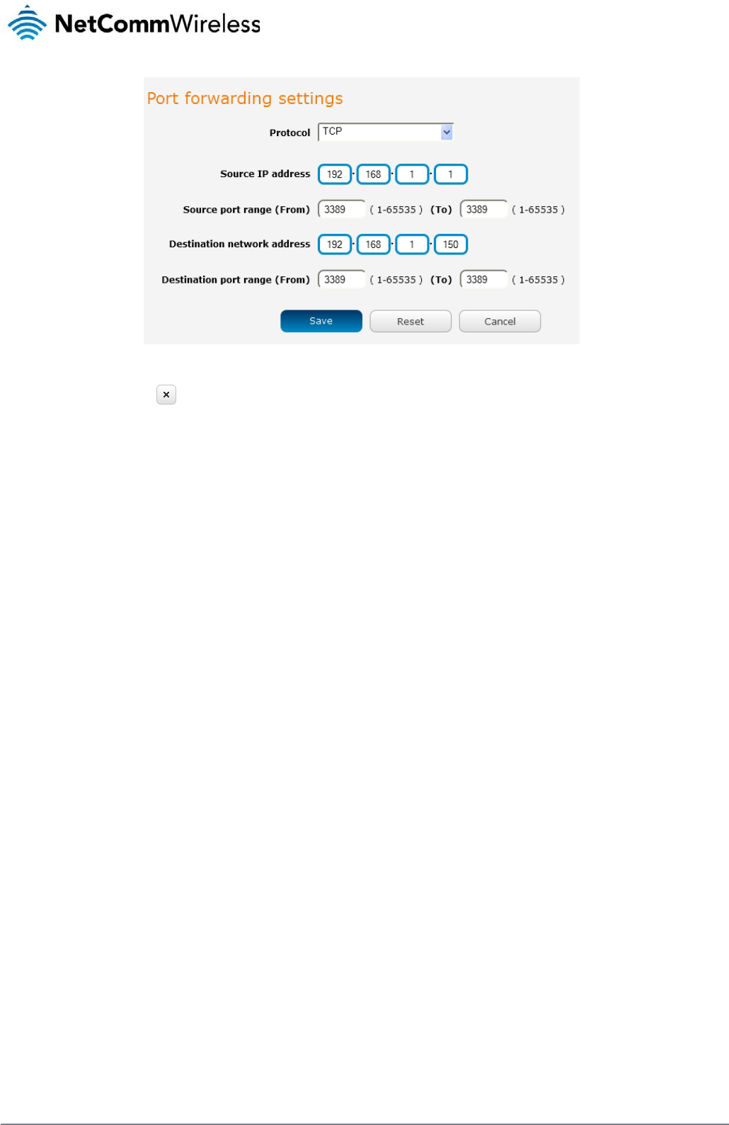
46
NetComm Wireless 3G Light Industrial M2M Route
r
www.netcommwireless.com
Figure 50 - Port forwarding settings
To delete a port forwarding rule, click the button on the Port forwarding list for the corresponding rule that you would like to delete.
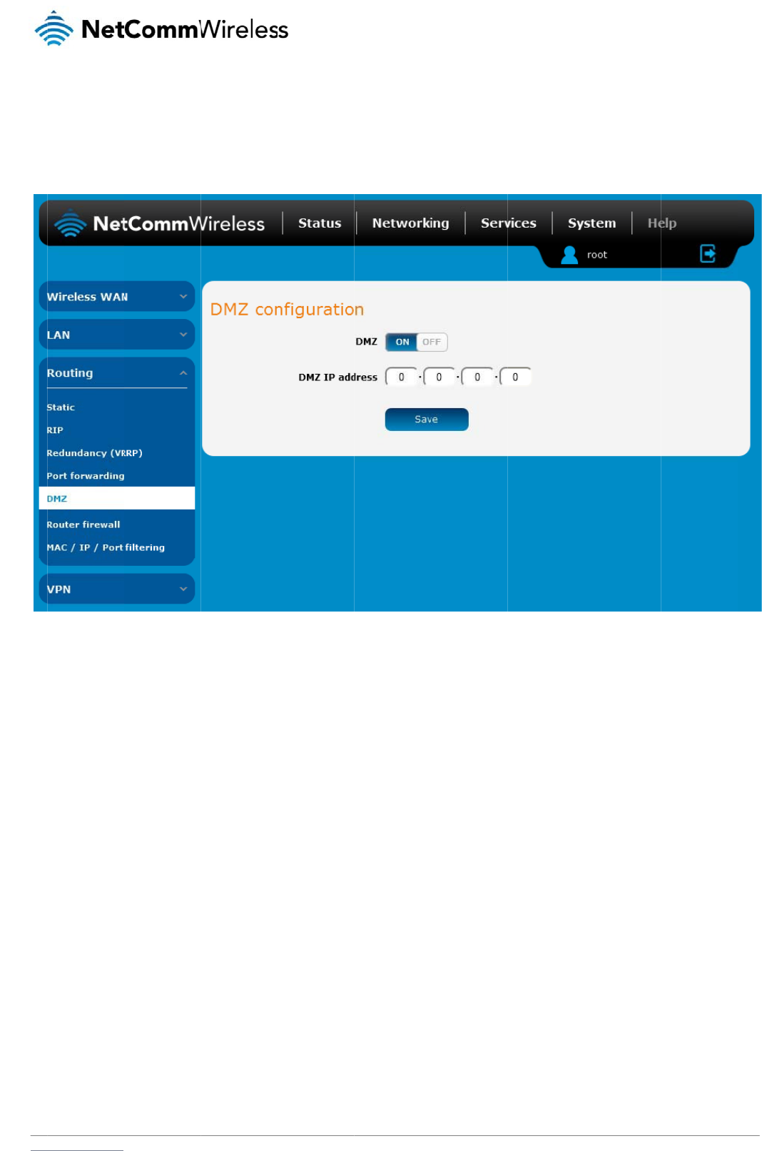
www
D
M
The
forw
The
.netcommwireless.com
M
Z
Demilitarized Zone (
arding rules, but it e
x
DMZ configuration
p
1. Click the D
2. Enter the I
P
3. Click the S
a
DMZ) allows you to
c
x
poses the device to
p
age is used to speci
MZ toggle key to tur
n
P
Address of the dev
a
ve button to save y
o
c
onfigure all incomin
g
untrusted networks
a
fy the IP Address of
n
the DMZ function
O
ice to be the DMZ h
o
o
ur settings.
g
traffic on all protoc
o
a
s there is no filterin
g
t
he device to use as
Fig
u
O
N.
o
st into the DMZ IP
A
ols to be forwarded
t
g
of what traffic is all
o
the DMZ host.
gu
re
51 - DMZ configu
r
A
ddress field.
t
o a selected device
o
wed and what is de
r
atio
n
N
e
behind the
r
outer. T
h
n
ied.
etComm Wireless 3G
h
is feature can be us
Light Industrial M2M
R
e
d to avoid complex
R
oute
r
47
port
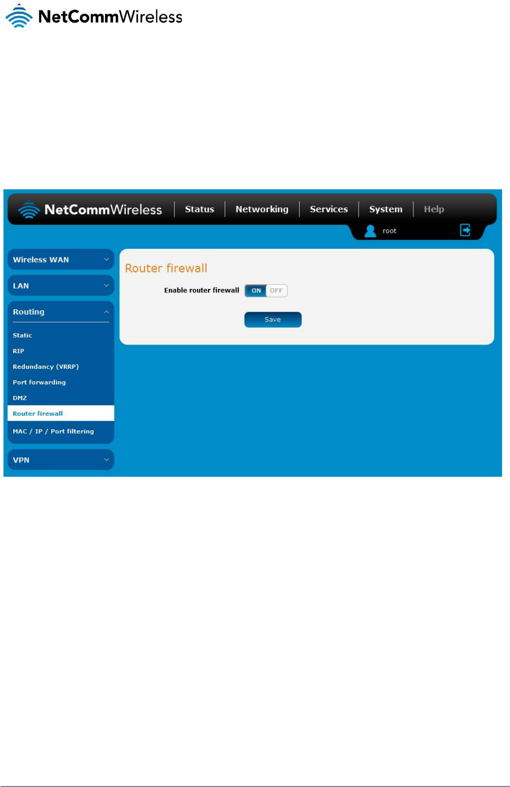
48
NetComm Wireless 3G Light Industrial M2M Route
r
www.netcommwireless.com
Router Firewall
The Router firewall page is used to enable or disable the in-built firewall on the router. When enabled, the firewall performs stateful packet inspection on inbound traffic from the wireless WAN
and blocks all unknown services, that is, all services not listed on the Services configuration page of the router.
With respect to the other Routing options on the Networking page, the firewall takes a low priority. The priority of the firewall can be described as:
DMZ > MAC/IP/Port filtering rules > MAC/IP/Port filtering default rule > Router firewall rules
In other words, the firewall is of the lowest priority when compared to other manual routing configurations. Therefore, a MAC/IP/Port filtering rule takes priority in the event that there is a conflict of
rules. When DMZ is enabled, MAC/IP/Port filtering rules and the router firewall are ignored but the router will still honour the configuration of the Remote router access control settings listed under
Administration Settings.
Figure 52 - Router Firewall toggle key
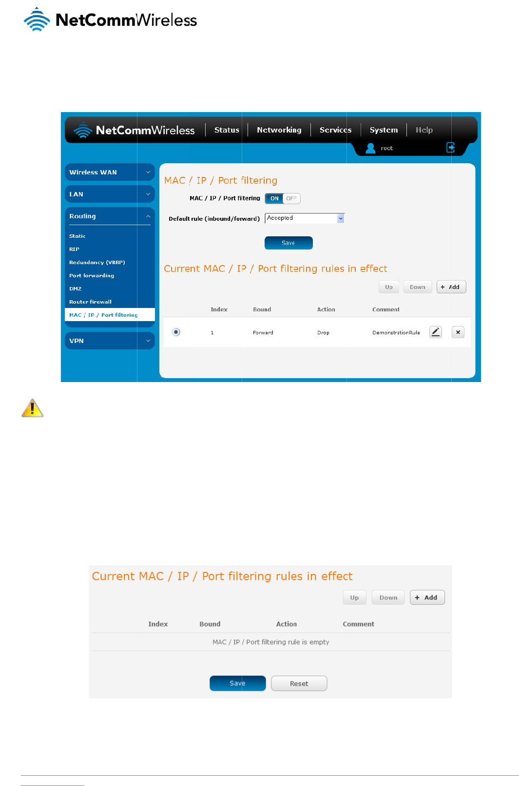
www
M
A
The
ena
b
“Dr
o
C
r
To
c
.netcommwireless.com
A
C / IP /
P
MAC/IP/Port filter fe
a
b
led with a default ru
o
pped”, all connectio
Note: When
MAC/IP to a
c
r
eating a
M
reate a filtering rule:
1. Click the
M
2. Using the
D
change thi
s
3. Click the S
a
4. In the Curr
e
5. Enter the d
P
ort filteri
n
a
ture allows you appl
le of “Accepted”, all
ns are denied exce
p
enabling MAC / IP /
c
cess the router, oth
e
M
AC / IP
/
M
AC / IP / Port filteri
n
D
efault rule (inbound
/
s
to Dropped, you sh
o
a
ve button to confir
m
e
nt MAC / IP / Port fil
t
etails of the rule in t
h
n
g
y a policy to the traf
f
connections will be
a
p
t for those listed in t
h
Port filtering and set
t
e
rwise you will not b
e
/
Port filte
r
n
g toggle key to swit
c
/
forward) drop down
o
uld first configure a
m
the default rule.
t
ering rules in syste
m
h
e section that is dis
p
ic that passes throu
g
a
llowed except thos
e
h
e filtering rules list.
Figur
e
t
ing the default rule t
o
e
able to access the
u
r
ing rule
c
h it to the ON positi
o
list, select the defau
filter rule that allows
m
section, click the +
A
Figure 54 - Curr
en
p
layed and click the
S
g
h the route
r
, both in
e
listed in the “Curre
n
e
53 - MAC / IP / Por
t
o
“Dropped”, you sh
o
u
ser interface of the
o
n.
lt action for the rout
e
at least one device
a
A
dd button.
e
nt MAC / IP/ Port fil
te
S
ave button.
b
ound and outboun
d
n
t MAC / IP / Port filte
t
filtering
o
uld ensure that you
router without resetti
n
e
r to take when traffic
a
ccess to the router,
te
ring rules in effec
t
N
e
d
, so that network ac
c
ring
r
ules in effect” li
have first added a fi
l
n
g the router to fact
o
reaches it. By defau
otherwise you will e
ff
etComm Wireless 3G
c
ess can be controll
e
i
st. Conversely, whe
n
ltering rule which all
o
o
ry default settings.
u
lt, this is configured
f
fectively be locked
o
Light Industrial M2M
R
e
d. When the filter is
n
the default rule is s
e
o
ws at least one kno
w
to Accepted. If you
o
ut of the router.
R
oute
r
49
e
t to
w
n
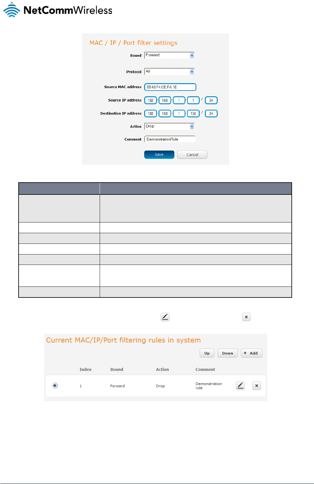
50
NetComm Wireless 3G Light Industrial M2M Route
r
www.netcommwireless.com
Figure 55 - MAC / IP / Port filtering settings
OPTION DESCRIPTION
Bound
Use the drop down list to select the direction of the traffic for which you want to apply to the rule. Inbound refers to all traffic that is entering the
router including data entering from the WAN and the LAN. Outbound refers to all traffic exiting the router including traffic leaving in the direction of
the WAN and traffic leaving in the direction of the LAN. Forward specifies traffic that enters on the LAN or WAN side and is forwarded to the
opposite end.
Protocol Use the drop down list to select the protocol for the rule. You can have the rule apply to All protocols, TCP, UDP, UDP/TCP or ICMP.
Source MAC Address Enter the MAC address in six groups of two hexadecimal digits separated by colons (:). e.g. 00:40:F4:CE:FA:1E
Source IP Address Enter the IPv4 address that the traffic originates from and the subnet mask using CIDR notation.
Destination IP Address Enter the IPv4 address that the traffic is destined for and the subnet mask using CIDR notation.
Action
Select the action to take for traffic which meets the above criteria. You can choose to Accept or Drop packets. When the default rule is set to Accept,
you cannot create a rule with an Accept action since the rule is redundant. Likewise, if the default rule is set to Dropped you cannot create a rule with
a Drop action.
Comment [Optional] Use this field to enter a comment as a meaningful description of the rule.
Table 14 - Current MAC / IP / Port filtering rules in effect
6. The new rule is displayed in the filtering rules list. You can edit the rule by clicking the Edit button or delete the rule by clicking the button.
Figure 56 - Completed filtering rule
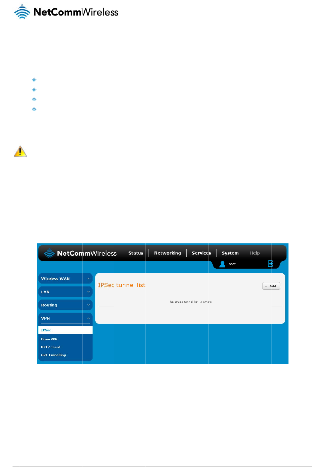
www
V
A Vi
r
gen
e
The
Eac
h
IP
S
IPS
e
rout
e
C
o
Fro
m
Clic
k
.netcommwireless.com
V
PN
r
tual Private Network
e
rally not visible to t
h
advantages of a VP
N
Data
P
Acce
s
Data
O
Data
I
h
VPN connection h
a
Note: The fo
website.
S
ec
e
c operates on Layer
er
supports IPsec en
o
nfigurin
g
m
the menu at the to
p
k
the +Add button to
(VPN) is a tunnel pr
o
h
e public network.
N
connection includ
e
P
rotection
s
s Control
O
rigin Authenticatio
n
Integrity
a
s different configura
t
llowing descriptions
r
3 of the OSI model
a
d points and can be
g
an IPSec
p
of the screen, click
begin configuring a
n
o
viding a private link
e
:
n
t
ion requirements. T
h
are an overview of t
h
a
nd as such can pro
t
configured with Site
VPN
Networking and und
n
IPSec VPN connec
t
between two netwo
r
h
e following pages d
e
h
e various VPN optio
n
t
ect higher laye
r
ed p
to Site VPN tunnels
w
er the VPN section,
c
Fig
t
ion.
r
ks or devices over a
etail the configuratio
ns available. More d
e
p
rotocols. IPSec is us
w
ith third party VPN
r
c
lick IPSec.
A
list of
Fi
gure
57 - IPSec VPN
L
public network. Dat
a
n
options available f
o
e
tailed instructions a
ed for both site to sit
r
outers.
configured IPSec V
P
L
is
t
N
e
a
to be sent via a VP
N
o
r the different VPN
c
r
e available in separ
a
e
VPN and Remote
A
P
N connections is di
s
etComm Wireless 3G
N
needs to be enca
p
c
onnection types.
ate whitepapers on t
A
ccess VPN. The 3G
s
played.
Light Industrial M2M
R
p
sulated and as suc
h
he NetComm Wirele
s
Light Industrial M2
M
R
oute
r
51
h
is
s
s
M
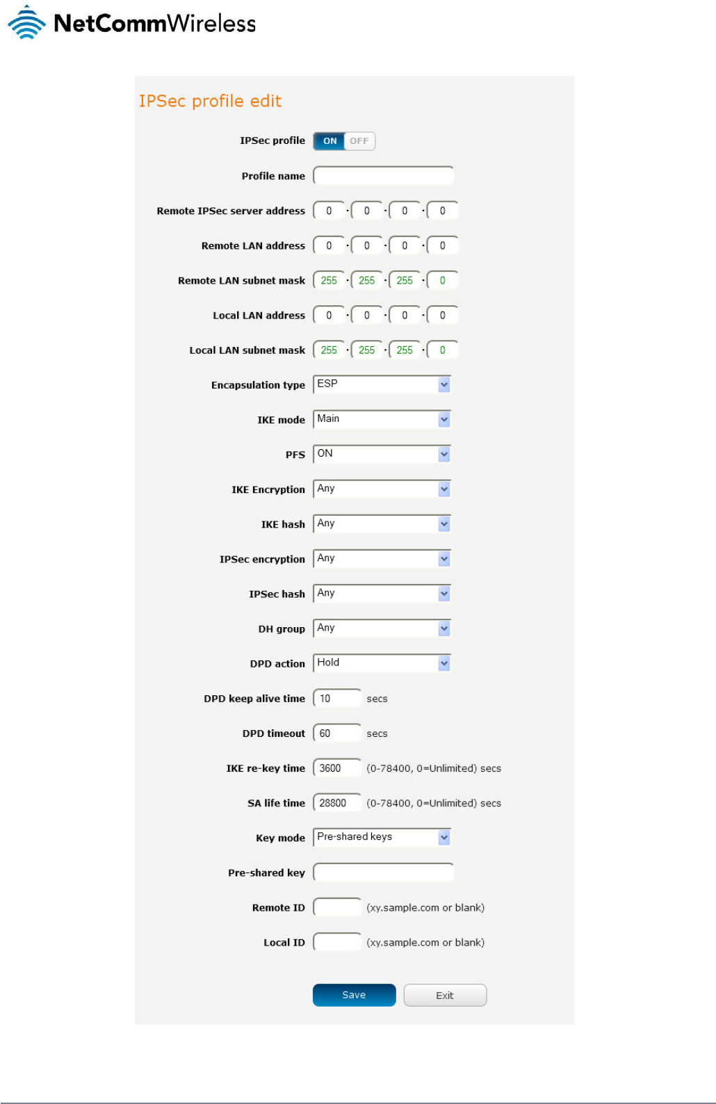
52
NetComm Wireless 3G Light Industrial M2M Route
r
www.netcommwireless.com
Figure 58 – IPSec profile edit

www
.netcommwireless.com
N
e
etComm Wireless 3G
Light Industrial M2M
R
R
oute
r
53

54
NetComm Wireless 3G Light Industrial M2M Route
r
www.netcommwireless.com
The following table describes each of the fields of the IPSec VPN Connection Settings page.
ITEM DEFINITION
IPSec profile Enables or disables the VPN profile.
Profile name A name used to identify the VPN connection profile.
Remote IPSec server address The IP address of the IPSec server.
Remote LAN address Enter the IP address of the remote network for use on the VPN connection.
Remote LAN subnet mask Enter the subnet mask in use on the remote network.
Local LAN address Enter the IP address of the local network for use on the VPN connection.
Local LAN subnet mask Enter the subnet mask in use on the local network.
Encapsulation type Select the encapsulation protocol to use with the VPN connection. You can choose ESP, AH or Any.
IKE mode Select the IKE mode to use with the VPN connection. You can choose Main, Aggressive or Any.
PFS Choose whether Perfect Forward Secrecy is ON or OFF for the VPN connection.
IKE encryption Select the cipher type to use for the Internet Key Exchange.
IKE hash Select the IKE Hash type to use for the VPN connection. The hash is used for authentication of packets for the key exchange.
IPSec encryption Select the IPSec encryption type to use with the VPN connection.
IPSec hash Select the IPSec hash type to use for the VPN connection. The hash is used for authentication of packets for the VPN connection.
DH group Select the desired Diffie-Hellman group to use. Higher groups are more secure but also require longer to generate a key.
DPD action Select the desired Dead Peer Detection action. This is the action to take when a dead Internet Key Exchange Peer is detected.
DPD keep alive time Enter the time in seconds for the interval between Dead Peer Detection keep alive messages.
DPD timeout Enter the time in seconds of no response from a peer before Dead Peer Detection times out.
IKE re-key time Enter the time in seconds between changes of the encryption key. To disable changing the key, set this to 0.
SA life time Enter the time in seconds for the security association lifetime.
Key mode
Select the type of key mode in use for the VPN connection. You can select from:
Pre Shared Key
RSA keys
Certificates
Pre-shared key The pre-shared key is the key that peers used to authenticate each other for Internet Key Exchange.
Remote ID Specifies the domain name of the remote network.
Local ID Specifies the domain name of the local network.
Update Time Displays the last time the key was updated.
Local RSA Key Upload Select the RSA key file for the local router here by clicking the Browse button.
Remote RSA Key Upload Select the RSA key file for the remote router here by clicking the Browse button.
Private key Passphrase The Private key passphrase of the router is the passphrase used when generating the router’s private key using OpenSSL CA.
Key / Certificate Select the type of key or certificate to use for authentication. You can select Local private key, Local public certificate, Remote public certificate, CA certificate, CRL certificate.
IPSec Certificate Upload Select the IPSec certificate to upload by clicking the Browse button.
Table 15 - IPSec Configuration Items
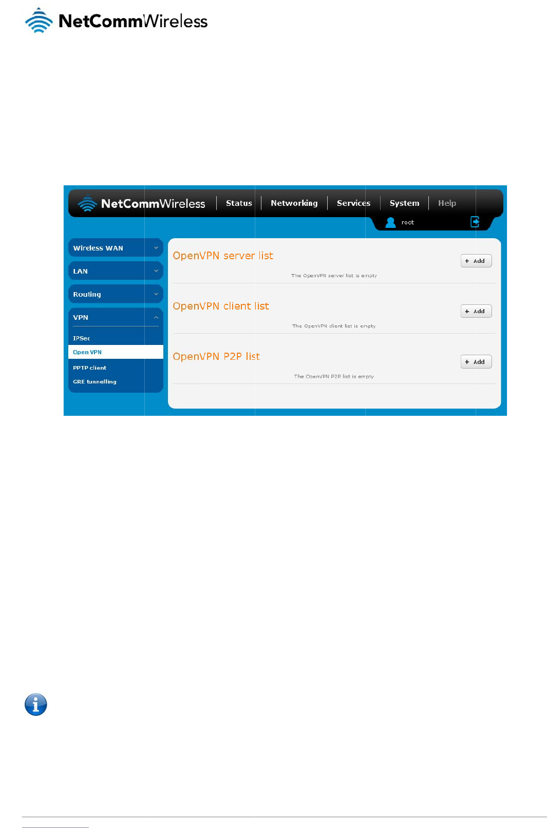
www
O
p
Ope
tran
s
tran
s
C
o
Fro
m
Clic
k
O
p
To
c
.netcommwireless.com
p
enVPN
nVPN is an open so
u
s
lation (NAT) and fir
e
s
ports. Support for
O
o
nfigurin
g
m
the menu at the to
p
k
the +Add button fo
r
p
enVPN S
e
onfigure an OpenVP
1. Click the O
2. Type a na
m
3. Use the Se
default pa
c
4. In the VPN
differs fro
m
5. Next to Dif
f
6. Under Ser
v
the Gener
a
7. Under the
S
Note: The
D
u
rce virtual private n
e
e
walls and allows au
t
O
penVPN is available
g
an Open
p
of the screen, click
r
the type of OpenVP
e
rver
N Server:
O
penVPN profile togg
m
e for the OpenVPN
s
e
rver port field to sel
e
c
ket type is UDP.
network address an
m
your existing addre
s
f
ie-Hellman paramet
e
v
er Certificates, ente
r
a
te CA certificate but
t
S
erver certificates s
e
D
iffie-Hellman param
e
e
twork (VPN) progra
m
t
hentication by ce
r
tifi
c
on several operatin
g
VPN serv
e
Networking and fro
m
N server/client you
w
le key to switch it to
t
s
erver profile you ar
e
e
ct a port number an
d
d VPN network sub
n
s
s scheme.
e
rs, click the Genera
t
r
the required details
t
on to generate the
C
e
ction, select the Aut
h
e
ters can take up to
1
m
for creating point-t
o
c
ate, pre-shared ke
y
g
systems, including
e
r
m
the VPN section on
Fi
gu
w
ould like to configur
e
t
he ON position.
e
creating.
d
then use the drop
d
n
et mask fields, ente
r
t
e DH button. This wi
.
All fields must be c
o
C
ertificate Authority (
C
h
entication type that
y
1
0 minutes to gener
a
o-point or server-to-
m
y
or username and p
a
Windows, Linux, Ma
c
the left, click Open
V
gu
re
59 - OpenVPN V
PN
e
.
d
own list to select a
p
r
the IP address and
i
ll create an encrypti
o
o
mpleted. The Coun
t
C
A) certificate base
d
you would like to us
e
a
te. Please be patien
t
m
ulti-client encrypte
d
a
ssword. OpenVPN
w
c
OS, Solaris, Open
B
V
PN.
A
list of configu
r
PN
Lis
t
p
acket type to use f
o
network subnet mas
o
n key to secure you
t
ry field must consist
d
on this information.
e
for the OpenVPN S
e
t
.
N
e
d
tunnels between ho
w
orks well through p
r
B
SD, FreeBSD, NetB
S
r
ed OpenVPN VPN c
r your OpenVPN Se
r
k
to assign to your V
P
r OpenVPN connecti
of two characters o
n
e
rver.
etComm Wireless 3G
o
st computers. It can
r
oxy servers and ca
n
S
D and QNX.
c
onnections is displa
y
r
ver. The default Op
e
P
N. This is ideally a
n
i
on.
n
ly. When the details
Light Industrial M2M
R
traverse network ad
d
n
run over TCP and U
y
ed.
e
nVPN port is 1194 a
n
internal IP address
w
have been entered,
R
oute
r
55
d
ress
DP
n
d
w
hich
click
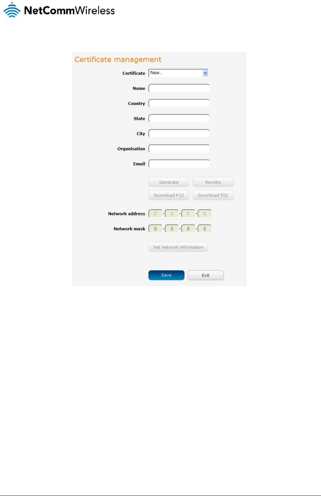
56
NetComm Wireless 3G Light Industrial M2M Route
r
www.netcommwireless.com
Certificate Authentication
In the Certificate Management section, enter the required details to create a client certificate. All fields are required. When you have finished entering the details, click the Generate button.
Figure 60 - OpenVPN server configuration – Certificate management
When it is done, you can click the Download P12 button or the Download TGZ button to save the certificate file depending on which format you would like. If for some reason the integrity of your
network has been compromised, you can return to this screen and use the Certificate drop down list to select the certificate and then press the Revoke button to disable it.
Optional: To inform the OpenVPN server of the network address scheme of the currently selected certificate, enter the network address and network subnet mask in the respective fields and
click the Set network information button. If you do not enter the remote subnet here, any packet requests from the server to the client will not be received by the client network because it is not
aware of the remote client’s subnet.
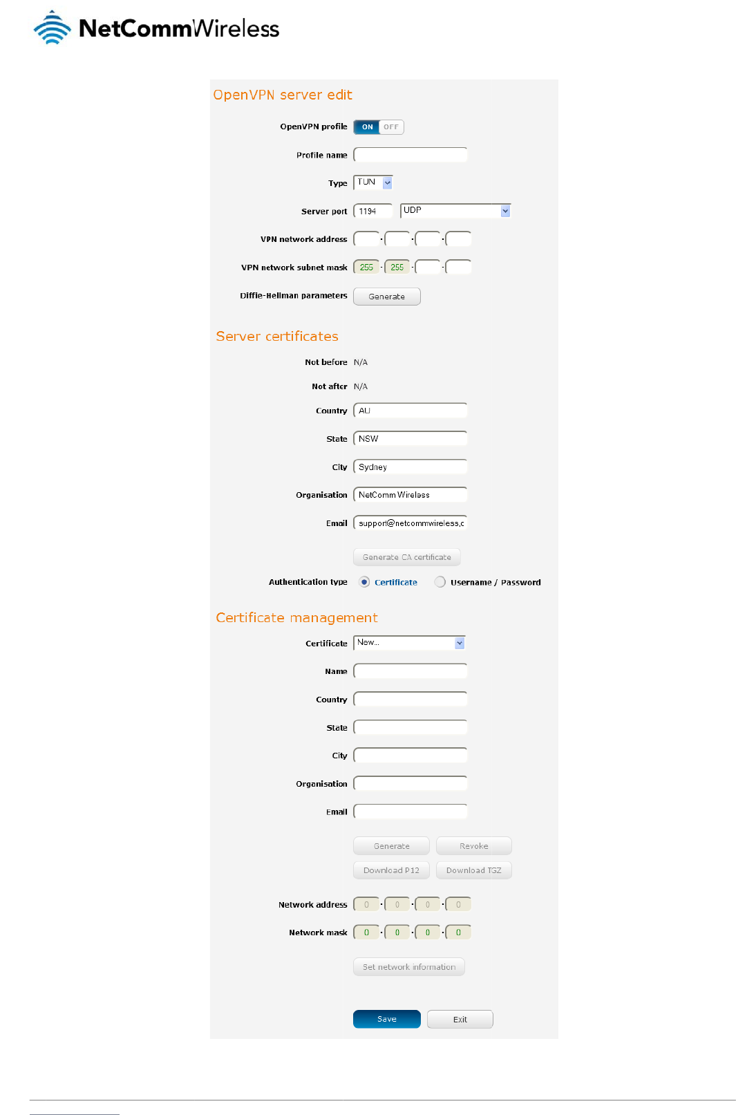
www
.netcommwireless.com
Figure 61 – OpenVPN server pr
o
o
file setting
s
N
e
etComm Wireless 3G
Light Industrial M2M
R
R
oute
r
57
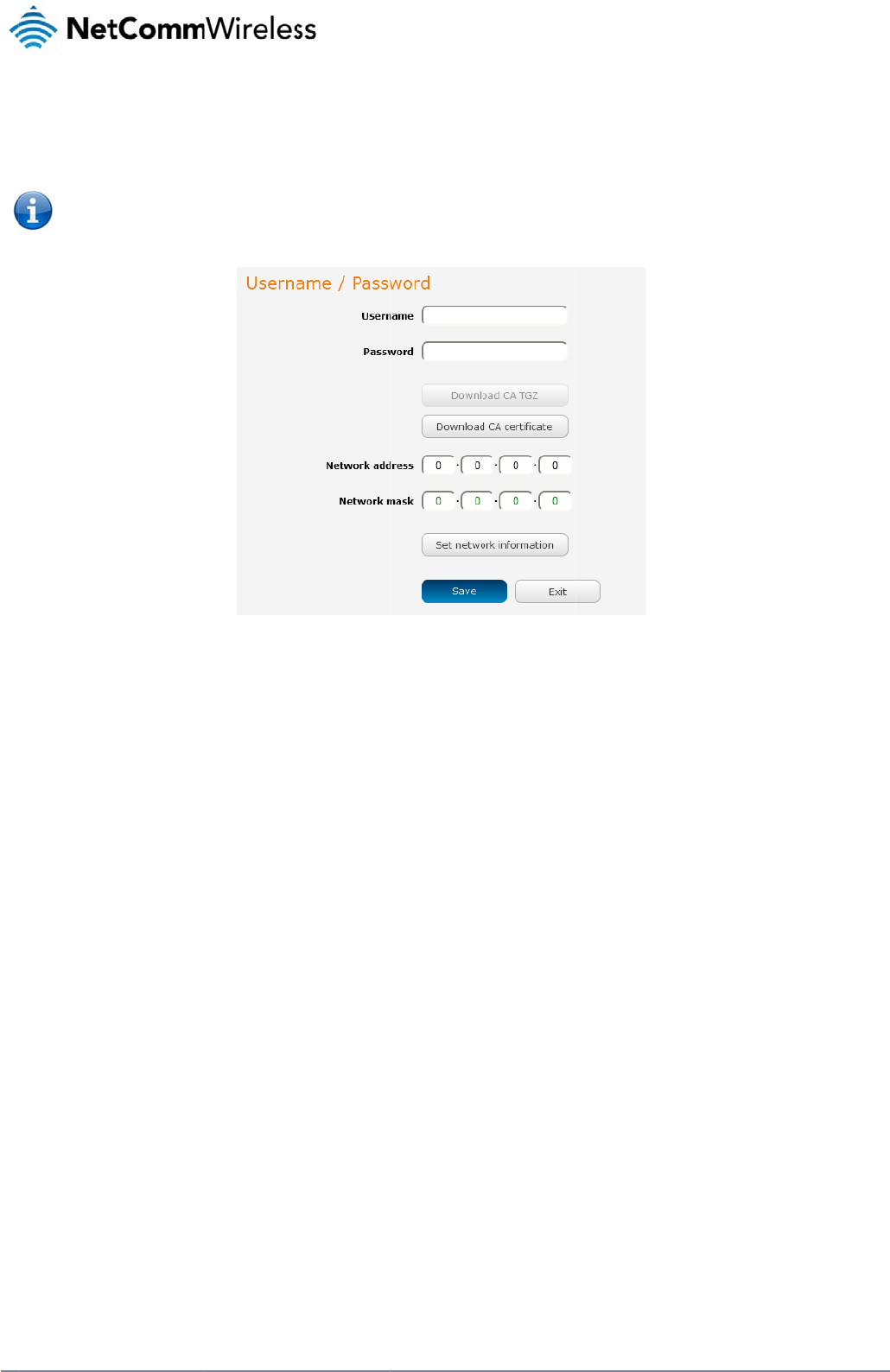
58
Net
C
Us
e
In th
ca.c
Opti
o
clic
k
awa
Wh
e
C
o
C
omm Wireless 3G Li
g
e
rname / Pas
s
e Username/Passw
o
r
t file. This file will ne
Note: If y
o
connecti
o
o
nal: To inform the
O
k
the Set Network Inf
o
re of the remote clie
n
e
n you have finished
e
o
nfigurin
g
1. Click the O
2. In the Profi
l
3. In the Serv
e
4. Use the Se
default pa
c
5. If the Defa
u
selected, t
h
6. Use the Au
g
ht Industrial M2M Ro
u
s
word Authe
n
o
rd section, enter the
ed to be provided to
o
u wish to have mor
e
o
n.
O
penVPN server of th
o
rmation button. If y
o
n
t’s subnet.
e
ntering all the requi
g
an Open
V
O
penVPN profile togg
le name field, type a
e
r IP address field, t
y
e
rve
r
port field to sel
e
c
ket type is UDP.
u
lt gateway option is
h
e OpenVPN conne
c
thentication type opt
u
te
r
n
tication
username and pass
the client.
e
than one client con
n
e network address s
o
u do not enter the r
e
red information, clic
k
V
PN Clie
n
le key to switch it to
t
name for the Open
V
y
pe the WAN IP add
e
ct a port number an
d
applied on the Ope
n
c
tion allows for secur
e
ions to select the Au
t
w
ord you would like
t
n
ect to this OpenVP
N
Figure 62 - OpenV
P
cheme of the curren
t
e
mote subnet here,
a
k
Save to finish confi
g
n
t
t
he ON position.
V
PN client profile you
r
ess of the OpenVP
N
d
then use the drop
d
n
VPN client page, th
e
e
communication lin
k
t
hentication type tha
t
to use for authentica
N
server, you must u
s
P
N Serve
r
– Usernam
e
t
ly selected certifica
t
a
ny packet requests
f
g
uring the OpenVPN
are creating.
N
server.
d
own list to select a
p
e
OpenVPN server w
i
k
s between this rout
e
t
you would like to u
s
tion on the OpenVP
N
s
e Certificate authen
t
e
/ Password section
t
e, enter the network
f
rom the server to th
e
server.
p
acket type to use f
o
i
ll enable connection
er
and the remote O
p
s
e for the OpenVPN
c
N
Server. Click the D
o
t
ication mode as Us
e
a
ddress and networ
k
e
client will not be re
c
r the OpenVPN serv
e
s
to be made to othe
enVPN serve
r
only.
c
lient.
o
wnload CA certifica
t
e
rname/Password on
k
subnet mask in the
c
eived by the client
n
e
r. The default Open
e
r client networks co
n
www.netcommwire
l
t
e button to save the
ly allows for a single
respective fields an
d
n
etwork because it is
V
PN port is 1194 an
d
n
nected to it. If it is n
o
l
ess.com
client
d
not
d
o
t
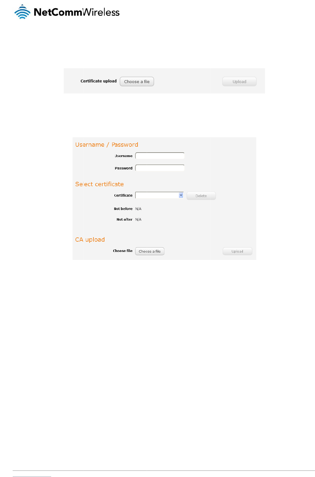
www
C
e
In th
sele
c
Us
e
Ent
e
Use
Clic
k
C
o
To
c
.netcommwireless.com
e
rtificate Aut
h
e Certificate upload
c
ted, click the Uploa
e
rname / Pas
s
e
r the username and
the Browse button t
o
k
the Save button to
o
nfigurin
g
onfigure an OpenVP
1. Set the Op
e
2. In the Profi
l
3. On the rou
t
h
entication
section at the botto
m
d button to send it t
o
s
word Authe
n
password to authent
o
locate the CA certi
f
complete the Open
V
g
an Open
V
N pee
r
-to-peer conn
e
nVPN profile toggle
le name field, type a
t
er designated as th
e
m
of the screen, click
o
the router.
n
tication
icate with the Open
V
f
icate file you saved
f
V
PN Client configurat
V
PN P2P
C
ection:
key to switch it to th
name for the Open
V
e
master, leave the S
the Browse button a
Figure 63 -
O
V
PN server.
Figure 64 - Open
V
f
rom the OpenVPN S
e
i
on.
C
onnectio
n
e
ON position.
V
PN P2P profile you
a
e
rver IP address fiel
d
nd locate the certific
O
penVPN
client - Cer
t
V
PN Clien
t
- Usernam
e
erver and then pres
s
n
a
re creating.
d
empty. On the rou
t
ate file you downloa
d
ti
ficate
upload
e
/Password sectio
n
s
the Upload button t
o
t
er designated as th
e
N
e
d
ed when you config
o
send it to the route
r
slave, enter the WA
etComm Wireless 3G
g
ured the OpenVPN
s
r
.
A
N IP address of the
m
Light Industrial M2M
R
s
erver. When it has b
m
aster.
R
oute
r
59
een
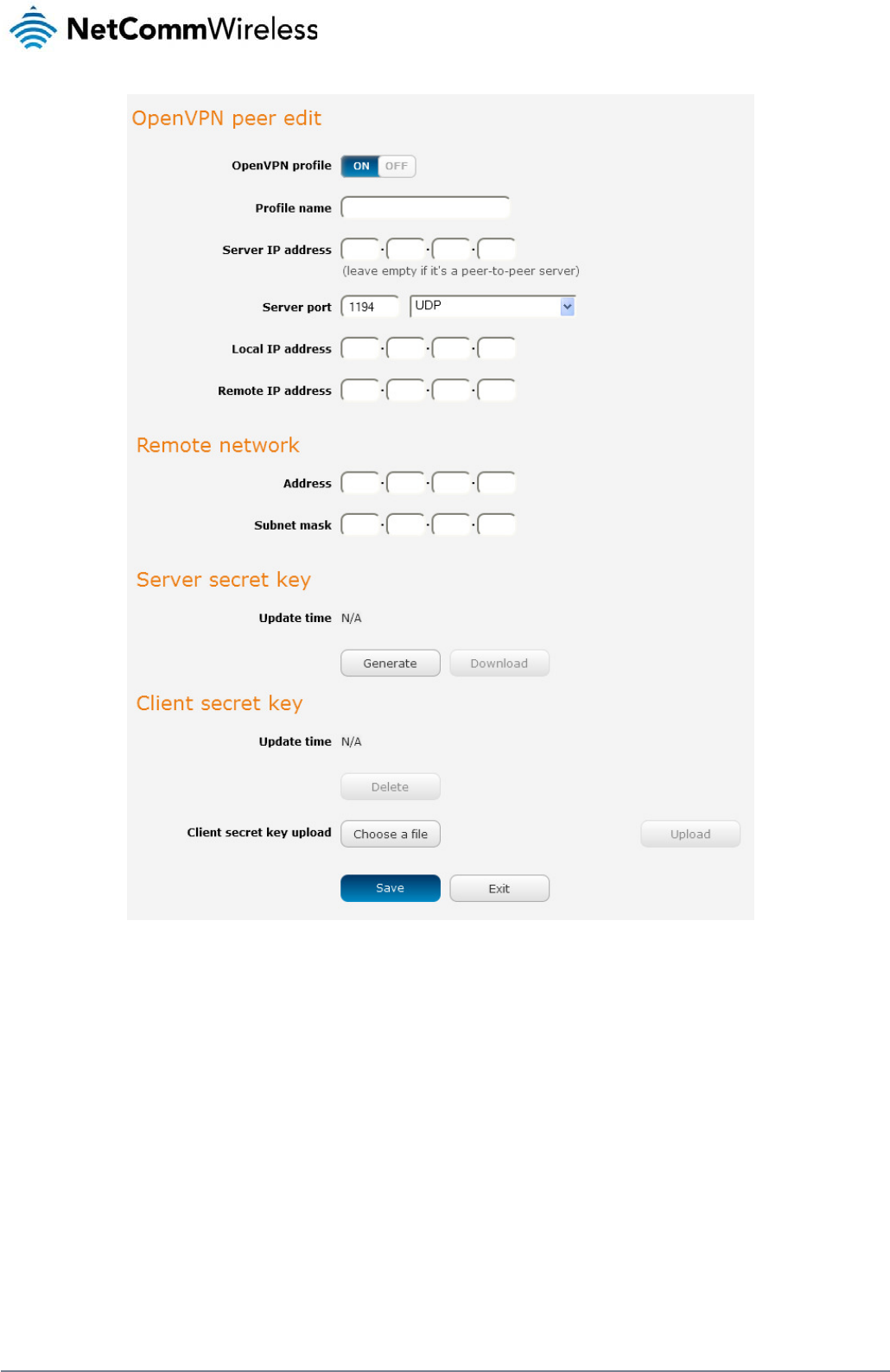
60
NetComm Wireless 3G Light Industrial M2M Route
r
www.netcommwireless.com
Figure 65 - OpenVPN P2P mode settings
4. Use the Server port field to select a port number and then use the drop down list to select a packet type to use for the OpenVPN server. The default OpenVPN port is 1194 and
default packet type is UDP.
5. In the Local IP Address and Remote IP Address fields, enter the respective local and remote IP addresses to use for the OpenVPN tunnel. The slave should have the reverse
settings of the master.
6. Under the Remote network section, enter the network Address and network Subnet mask. The Network Address and Network Mask fields inform the Master node of the LAN
address scheme of the slave.
7. Press the Generate button to create a secret key to be shared with the slave. When the timestamp appears, you can click the Download button to save the file to exchange with the
other router.
8. When you have saved the secret key file on each router, use the Browse button to locate the secret key file for the master and then press the Upload button to send it to the slave.
Perform the same for the other router, uploading the slave’s secret key file to master.
9. When they are uploaded click the Save button to complete the peer-to-peer OpenVPN configuration.
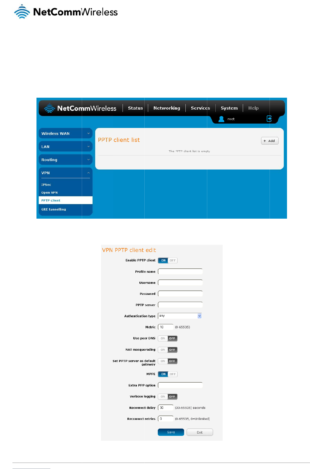
www
P
P
The
OSI
C
o
To
c
.netcommwireless.com
P
TP-Client
Point-to-Point Tunne
model and is includ
e
o
nfigurin
g
onfigure the PPTP cl
1. From the
m
2. Click the +
A
t
lling Protocol (PPTP)
e
d on Windows com
p
g
the PPTP
ient:
m
enu bar at the top o
f
A
dd button to begin
c
is a method for impl
e
p
uters.
Client
f
the screen, click N
e
c
onfiguring a new P
P
e
menting virtual priv
a
e
tworking and then fr
o
Fig
P
TP client profile. Th
e
Fig
ur
a
te networks using a
o
m the VPN section
Fi
gure
66 - PPTP clien
t
e
PPTP client edit sc
r
u
re
67 -
V
PN PPTP cli
en
TCP and GRE tunn
e
on the left side of th
e
t
lis
t
r
een is displayed.
en
t edi
t
N
e
e
l to encapsulate PP
P
e
screen, click PPTP
etComm Wireless 3G
P
packets. PPTP ope
client. The PPTP cli
e
Light Industrial M2M
R
rates on Layer 2 of t
h
e
nt list is displayed.
R
oute
r
61
h
e

62
NetComm Wireless 3G Light Industrial M2M Route
r
www.netcommwireless.com
3. Click the Enable PPTP client toggle key to switch it to the ON position.
4. In the Profile name list, enter a profile name for the tunnel. This may be anything you like and is used to identify the tunnel on the router.
5. Use the Username and Password fields to enter the username and password for the PPTP account.
6. In the PPTP server address field, enter the IP address of the PPTP server.
7. From the Authentication type drop down list, select the Authentication type used on the server. If you do not know the authentication method used, select any and the router will
attempt to determine the correct authentication type for you. There are 5 authentication types you can choose from:
CHAP – uses a three way handshake to authenticate the identity of a client.
MS-CHAP v1 – This is the Microsoft implementation of the Challenge Handshake Authentication Protocol for which support was dropped in Windows® Vista.
MS-CHAP v2 - This is the Microsoft implementation of the Challenge Handshake Authentication Protocol which was introduced in Windows® NT 4.0 and is still supported
today.
PAP – The Password Authentication Protocol uses a password as a means of authentication and as such, is commonly supported. PAP is not recommended because it
transmits passwords unencrypted and is not secure.
EAP – Extensible Authentication Protocol. An Authentication protocol commonly used in wireless networks.
8. The metric value helps the router to prioritise routes and must be a number between 0 and 65535. The default value is 30 and should not be modified unless you are aware of the
effect your changes will have.
9. The Use peer DNS option allows you to select whether the remote clients will use the Domain Name Server of the PPTP server. Click the toggle key to set this to ON or OFF as
required.
10. NAT masquerading allows the router to modify the packets sent and received to inform remote computers on the internet that packets originating from a machine behind the router
actually originated from the WAN IP address of the router’s internal NAT IP address. Click the toggle key to switch this to the ON position if you want to use this feature.
11. Set default route to PPTP sets all outbound data packets to go out through the PPTP tunnel. Click the toggle key to switch this to the ON position if you want to use this feature.
12. The Verbose logging option sets the router to output detailed logs regarding the PPTP connection in the System Log section of the router interface.
13. The Reconnect delay is the time in seconds that the router will wait before attempting to connect to the PPTP server in the event that the connection is broken. The minimum time to
wait is 30 seconds so as to not flood the PPTP server with connection requests, while the maximum time to wait is 65335 seconds.
14. The Reconnect retries is the number of connection attempts that the router will make in the event that the PPTP connection goes down. If set to 0, the router will retry the connection
indefinitely, otherwise the maximum number of times to retry cannot be greater than 65335.
15. Click the Save button to save the changes. The VPN will attempt to connect after your click Save. Click the Status button at the top left of the interface to return to the status window
and monitor the VPN’s connection state.
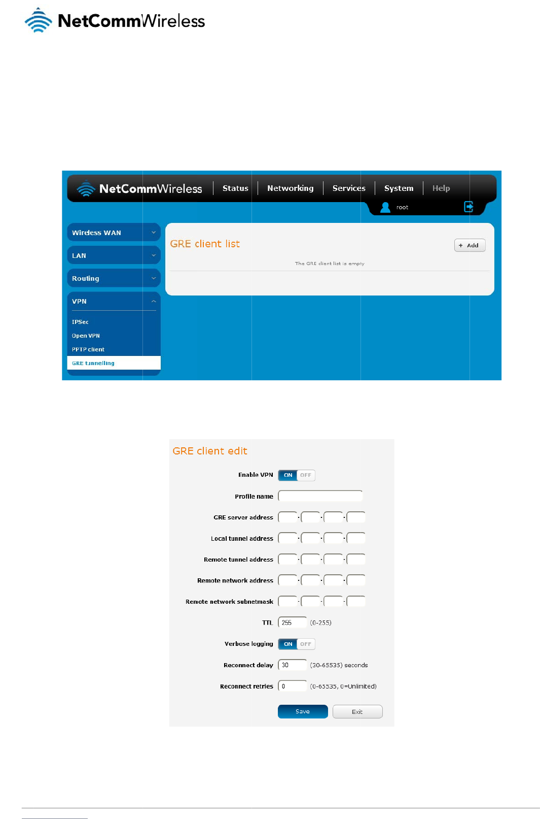
www
G
R
The
clie
n
C
o
To
c
.netcommwireless.com
R
E tunnel
l
Generic Route Enca
n
ts only. Once a PPT
P
o
nfigurin
g
onfigure GRE tunnel
1. From the
m
2. Click the +
A
3. Click the E
n
l
ing
psulation (GRE) prot
o
P
control session est
g
GRE tun
n
ling:
m
enu bar at the top o
f
A
dd button to begin
c
nable GRE Tunnel t
o
o
col is used in additi
ablishes the VPN tu
n
n
elling
f
the screen, click N
e
c
onfiguring a new G
R
o
ggle key to switch it
on to Point-to-Point
T
n
nel GRE is used to
s
e
tworking and then fr
o
Fi
R
E tunnelling client
p
F
ig
to the ON position.
T
unnelling Protocol (
P
s
ecurely encapsulat
e
o
m the VPN section
F
igure
68 - GRE clien
t
p
rofile. The GRE Clie
n
ig
ure
69 – GRE client
e
P
PTP) to create VPN
s
e
the data or payload
on the left side of th
e
lis
t
n
t Edit screen is disp
e
di
t
N
e
s
(virtual private net
w
.
e
screen, click GRE.
layed.
etComm Wireless 3G
w
orks) between clien
t
The GRE client list i
s
Light Industrial M2M
R
t
s and servers or bet
w
s
displayed.
R
oute
r
63
w
een

64
NetComm Wireless 3G Light Industrial M2M Route
r
www.netcommwireless.com
4. In the Profile name, enter a profile name for the tunnel. This may be anything you like and is used to identify the tunnel on the router.
5. In the GRE server address field, enter the IP address of the GRE server.
6. In the Local tunnel address field, enter the IP address you want to assign the tunnel locally.
7. In the Remote tunnel address field, enter the IP address you want to assign to the remote tunnel.
8. In the Remote network address field, enter the IP address scheme of the remote network.
9. In the Remote network subnetmask field, enter the subnet mask of the remote network.
10. The TTL (Time To Live) field is an 8-bit field used to remove an undeliverable data packet from a network to avoid unnecessary network traffic across the internet. The default value
of 255 is the upper limit on the time that an IP datagram can exist. The value is reduced by at least one for each hop the data packet takes to the next router on the route to the
datagram’s destination. If the TTL field reaches zero before the datagram arrives at its destination the data packet is discarded and an error message is sent back to the sender.
11. The Verbose logging option sets the router to output detailed logs regarding the GRE tunnel in the System Log section of the router interface.
12. The Reconnect delay is the time in seconds that the router will wait before attempting to connect to the GRE server in the event that the connection is broken. The minimum time to
wait is 30 seconds so as to not flood the GRE server with connection requests, while the maximum time to wait is 65335 seconds.
13. The Reconnect retries is the number of connection attempts that the router will make in the event that the GRE connection goes down. If set to 0, the router will retry the connection
indefinitely, otherwise the maximum number of times to retry cannot be greater than 65335.
14. Click the Save button to save the changes. The VPN will attempt to connect after your click Save. Click the Status button at the top left of the interface to return to the status window
and monitor the VPN’s connection state.
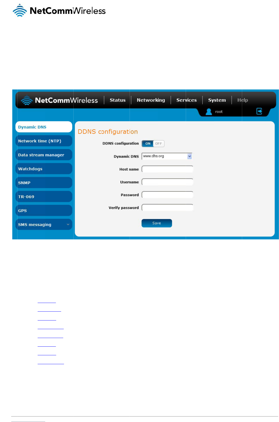
www
S
D
The
Dyn
a
To
c
.netcommwireless.com
S
er
v
D
ynami
c
DDNS page is used
a
mic DNS provides
a
onfigure dynamic D
N
1. Click the D
2. From the D
www.
d
www.
d
www.
d
www.
e
www.
j
www.
o
www.
t
www.
z
3. In the User
4. Click the S
a
v
ic
e
c
DNS
to configure the Dyn
a
method for the rout
e
N
S:
DNS configuration t
o
ynamic DNS drop d
o
d
hs.org
d
yndns.org
d
yns.cx
e
asydns.com
j
ustlinux.com
o
ds.org
t
zo.com
z
oneedit.com
r
name and Password
a
ve button to save t
h
e
s
amic DNS feature of
e
r to update an exte
r
o
ggle key to switch it
o
wn list, select the D
y
fields, enter the log
o
h
e DDNS configurati
o
the router. A numbe
Figur
e
r
nal name server wit
h
to the ON position.
y
namic DNS service
o
n credentials for yo
u
o
n settings.
r of Dynamic DNS h
o
e
70 – Dynamic DNS
s
h
the current WAN IP
that you wish to use
u
r DDNS account. E
n
o
sts are available fro
m
s
ettings
address.
.
The available DDN
S
n
ter the password fo
r
N
e
m
which to select.
S
services available
a
the account again i
n
etComm Wireless 3G
a
re:
n
the Verify passwor
d
Light Industrial M2M
R
d
field.
R
oute
r
65
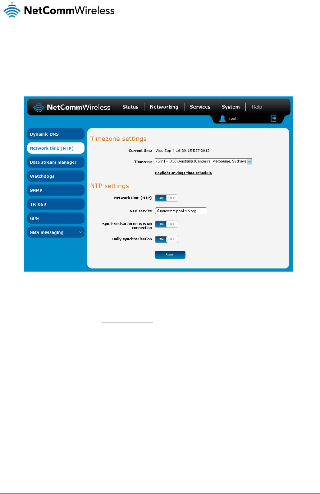
66
NetComm Wireless 3G Light Industrial M2M Route
r
www.netcommwireless.com
Network time (NTP)
The NTP (Network Time Protocol) settings page allows you to configure the 3G Light Industrial M2M router to synchronize its internal clock with a global Internet Time server and specify the time
zone for the location of the router. This provides an accurate timekeeping function for features such as System Log entries and Firewall settings where the current system time is displayed and
recorded.
Any NTP server available publicly on the internet may be used. The default NTP server is 0.netcomm.pool.ntp.org.
Figure 71 - NTP settings
Configuring Timezone settings
To configure time zone settings:
1. The Current time field shows the time and date configured on the router. If this is not accurate, use the Time zone drop down list to select the correct time zone for the router. If the
selected zone observes daylight savings time, a Daylight savings time schedule link appears below the drop down list. Click the link to see the start and end times for daylight
savings.
2. When you have selected the correct time zone, click the Save button to save the settings.
Configuring NTP settings
To configure NTP settings:
1. Click the Network time (NTP) toggle key to switch it to the ON position.
2. In the NTP service field, enter the address of the NTP server you wish to use.
3. The Synchronization on WWAN connection toggle key enables or disables the router from performing a synchronization of the time each time a mobile broadband connection is
established.
4. The Daily synchronisation toggle key enables or disables the router from performing a synchronization of the time each day.
5. When you have finished configuring NTP settings, click the Save button to save the settings.
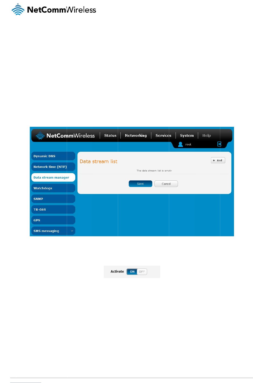
www
D
The
pro
c
Kit.
The
out
p
NM
E
The
.netcommwireless.com
D
ata str
e
data stream manag
e
c
essing by each virtu
data stream manag
e
p
uts of the router. Ce
r
E
A format) through t
h
following is an exam
1. Click the +
A
2. Click the A
c
3. In the Data
4. Under the
E
5. Under the
E
the serial p
e
am
m
e
r provides you with
t
al data tunnel. Cust
o
e
r provides a wide ra
r
tain accessories co
n
h
e built-in serial port
o
ple of how to config
u
A
dd button on the ri
g
c
tivate toggle key so
stream name field,
e
E
ndpoint A section,
u
E
ndpoint B section,
u
p
ort output. The scre
e
m
anage
r
t
he ability to create
m
o
mers interested in d
e
nge of possibilities
a
n
nected via the USB
o
r out of the USB po
r
u
re the router to sen
d
g
ht side of the page.
that it is in the ON
p
e
nter a name to iden
t
u
se the Type drop d
o
u
se the Type drop d
o
e
nshot below shows
a
r
m
appings between in
e
veloping their own
a
nd expands upon si
m
port such as USB to
r
t using a USB to Ser
d
GPS data through t
h
Fi
g
osition.
F
ig
t
ify the mapping on t
o
wn list to select GP
S
o
wn list to select Seri
a
a
n example of typic
a
n
put ports and outpu
t
a
pplications to creat
e
m
ple PAD functional
i
Serial cables are al
s
r
ial cable.
h
e serial port:
ig
ure
72 - Data strea
m
ig
ure
73 -
A
ctivate bu
t
t
he Data stream list.
S
.
al. Under the Serial
p
a
l settings for this sc
e
t
ports (e.g. Serial P
o
e
custom mappings
c
ty to include the for
w
s
o supported. For ex
a
m
lis
t
t
to
n
p
ort settings section,
e
nario.
N
e
rt, SMS, GPS, USB)
a
c
an contact NetCom
w
arding and translati
o
a
mple, you could se
n
use the drop down l
etComm Wireless 3G
a
nd performs any re
q
m Wireless about ou
o
n of data between
a
n
d the GPS data rec
e
l
ists to select the ap
p
Light Industrial M2M
R
q
uired translation or
d
r Software Develop
m
a
ny of the inputs and
e
ived by the module
p
ropriate parameters
R
oute
r
67
d
ata
m
ent
(in
for
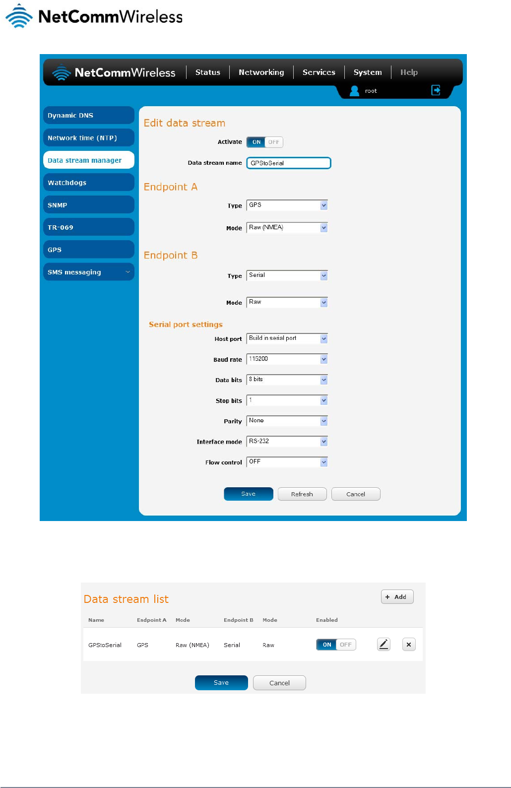
68
NetComm Wireless 3G Light Industrial M2M Route
r
www.netcommwireless.com
Figure 74 - Data stream manager - GPS to Serial port example
6. Click the Save button to confirm your settings. The new data stream appears in the Data stream list.
Table 16 - Data stream list entry
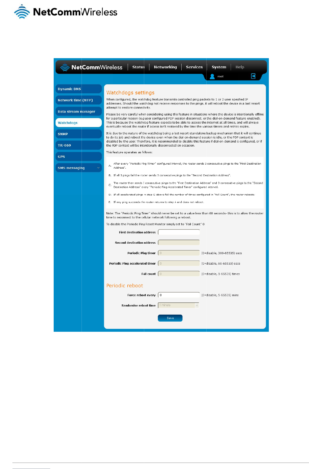
www
W
To
a
Wat
c
con
t
reb
o
We
r
This
the
f
It is
d
the
m
be i
n
.netcommwireless.com
W
atchd
o
ccess the Watchdo
g
c
hdogs are features
w
t
rolled ping packets
t
o
ot the device in a la
s
r
ecommend using c
a
is because the watc
f
ail count is reached.
d
ue to the nature of
t
m
obile broadband c
o
n
tentionally disconn
e
o
gs
g
s page, click the Se
w
hich monitor the ro
t
o 1 or 2 use
r
specifi
e
s
t resort attempt to r
e
a
ution when implem
e
c
hdog expects to be
a
t
he watchdog being
a
o
nnection is disable
d
e
cted on occasion.
rvices menu item, th
e
uter for anomalies a
n
e
d IP addresses to c
e
store connectivity.
e
nting this feature in
s
a
ble to access the i
n
a
last resort standal
o
d
by the user. Theref
o
e
n select the Watchd
Fig
u
n
d restart the router i
f
onfirm an active con
n
s
ituations where the
d
n
ternet at all times, a
n
o
ne backup mechani
s
o
re, we recommend
e
d
ogs menu item on th
u
re
75 - Watchdogs S
e
f
an anomaly occurs
nection. If the watch
d
d
evice is intentionall
y
n
d will always event
u
sm that it will contin
u
e
d that you disable t
h
e left.
e
tting
s
preventing its norm
a
d
og does not receiv
e
y
offline for a particul
a
ally reboot the route
r
u
e to do its job and r
e
h
is feature if Dial-on-
d
N
e
a
l operation. When c
o
e
responses to the pi
n
a
r reason, for examp
r
if access isn't resto
r
e
boot the device eve
n
d
emand is configure
d
etComm Wireless 3G
o
nfigured, the watch
d
ngs afte
r
a specified
p
le, when Dial-on-de
m
red by the time the v
n when the Dial-on-
d
d
or if the mobile bro
Light Industrial M2M
R
d
ogs feature transmi
t
number of failures, i
m
and has been ena
b
arious timers expire
a
d
emand session is id
l
adband connection
w
R
oute
r
69
t
s
t will
b
led.
a
nd
l
e, or
w
ill
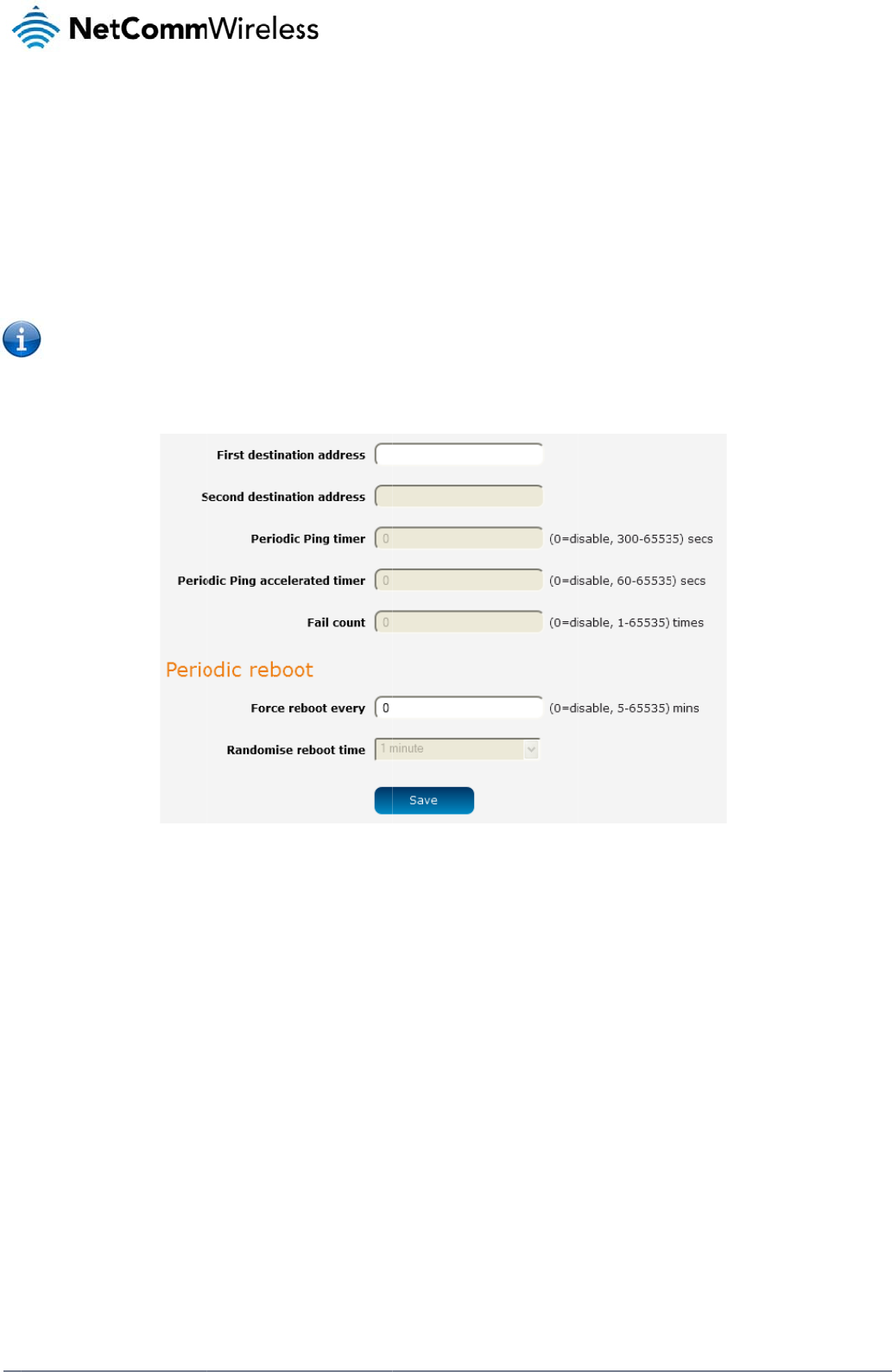
70
Net
C
The
To
d
C
omm Wireless 3G Li
g
watchdog works as
f
a) The router
s
b) If all 3 ping
c) If all 3 ping
d) If all 3 acc
e
e) If all 3 acc
e
f) When the
n
Note: The P
e
d
isable the periodic
p
g
ht Industrial M2M Ro
u
f
ollows:
s
ends 3 consecutive
s to the first destinat
s to the second des
t
e
lerated pings to the
e
lerated pings to the
n
umber of failures re
a
e
riodic Ping timer sh
o
p
ing reset monitor, s
e
u
te
r
pings to the first de
s
ion address fail, the
r
t
ination address fail,
t
first destination add
r
second destination
a
a
ches the number c
o
o
uld not be set to a
v
e
t Fail count to 0.
s
tination address at t
r
outer sends 3 cons
e
t
he router sends 3 pi
r
ess fail, the router s
e
a
ddress fail, the rout
e
o
nfigured in the Fail
c
v
alue of less than 21
0
Figur
e
t
he interval specified
e
cutive pings to the
s
ngs to the first desti
n
e
nds 3 pings to the
s
e
r registers this as a
c
ount field, the route
r
0
seconds to allow th
e
76 – Ping watchdog
s
in the Periodic Ping
s
econd destination a
d
n
ation address using
s
econd destination a
d
fail and returns to st
e
r
reboots. If any ping
e router time to reco
s
etting
s
timer field.
d
dress at the Periodi
c
the Periodic Ping a
c
d
dress at the Periodi
c
e
p C.
succeeds, the route
r
n
nect to the cellular
n
c Ping timer interval
.
c
celerated timer inte
r
c Ping accelerated t
i
r returns to step A a
n
network following a
r
www.netcommwire
l
r
val.
me
r
interval.
n
d does not reboot.
e
boot.
l
ess.com

www
C
o
The
To
c
D
i
To
d
C
o
The
reb
o
.netcommwireless.com
o
nfigurin
g
Periodic Ping settin
g
onfigure the ping w
a
1. In the First
2. In the Sec
o
3. In the Peri
o
watchdog
f
4. In the Peri
o
to the seco
5. In the Fail
c
watchdog
f
i
sabling t
h
d
isable the Periodic
P
Note: The traf
f
o
nfigurin
g
router can be config
o
ot if some anomaly
o
1. In the Forc
e
reboots is
5
2. If you have
preventing
time and t
h
3. Click the S
a
g
Periodic
g
s configure the rout
e
a
tchdog:
destination address
o
nd destination addr
e
o
dic Ping timer field,
f
unction.
o
dic Ping accelerate
d
nd destination addr
e
c
ount field, enter an
i
f
unction.
h
e Periodi
c
P
ing reset function, s
e
f
ic generated by the
g
a Period
i
ured to automaticall
y
o
ccurs.
e
reboot eve
r
y field,
5
minutes while the
m
configured a forced
a large number of d
e
h
en randomly reboot
w
a
ve button to save t
h
Ping setti
n
e
r to transmit controll
field, enter a websit
e
e
ss field, enter a we
b
enter an integer bet
w
d
timer field, enter a
n
e
ss. Setting this to 0
d
i
nteger between 1 a
n
c
Ping res
e
e
t Fail count to 0.
periodic ping featur
e
i
c reboot
y
reboot after a perio
d
enter the time in min
m
aximum value is 65
5
reboot time, you ca
n
e
vices from rebootin
g
w
ithin the configure
d
h
e settings.
n
gs
ed ping packets to
2
e
address or IP addr
e
b
site address or IP a
d
w
een 300 and 65535
integer between 60
d
isables the ping wa
t
n
d 65535 for the nu
m
e
t functio
n
e
is usually counted
a
d
of time specified i
n
u
tes between forced
5
35 minutes.
n
use the Randomis
e
g
simultaneously an
d
d
Randomise reboot
t
2
specified IP addres
e
ss to which the rout
d
dress to which the r
for the number of s
e
and 65535 for the n
u
tchdog function
m
ber of times an acc
e
n
a
s chargeable data
u
n
minutes. While this
reboots. The defaul
t
e
reboot time drop d
o
d
flooding the netwo
r
time.
ses. If the router do
e
er should send the fi
outer should send th
e
conds the router sh
o
u
mber of seconds th
e
e
lerated ping should
u
sage. Please keep
t
is not necessary, it d
t
value is 0 which dis
o
wn list to select a ra
r
k with connection at
t
N
e
s not receive respon
r
st round of ping req
e
second round of p
i
o
uld wait between pi
n
e
router should wait
b
f
ail before the router
his in mind when sel
e
oes ensure that in th
e
a
bles the Periodic r
e
n
dom reboot timer.
R
empts. The router wi
etComm Wireless 3G
n
ses to the pings, th
e
uests.
ing requests.
n
g attempts. Setting
b
etween accelerate
d
reboots. Setting this
ecting how often to
p
e case of remote ins
e
boot function. The
m
R
andomising the reb
o
i
ll wait for the config
u
Light Industrial M2M
R
e
router will reboot.
t
his to 0 disables th
e
d
ping attempts, i.e.
p
to 0 disables the pi
n
p
ing.
t
allations, the router
w
m
inimum period betw
e
o
ot time is useful for
u
red Force reboot ev
R
oute
r
71
e
ping
p
ings
n
g
w
ill
e
en
ery
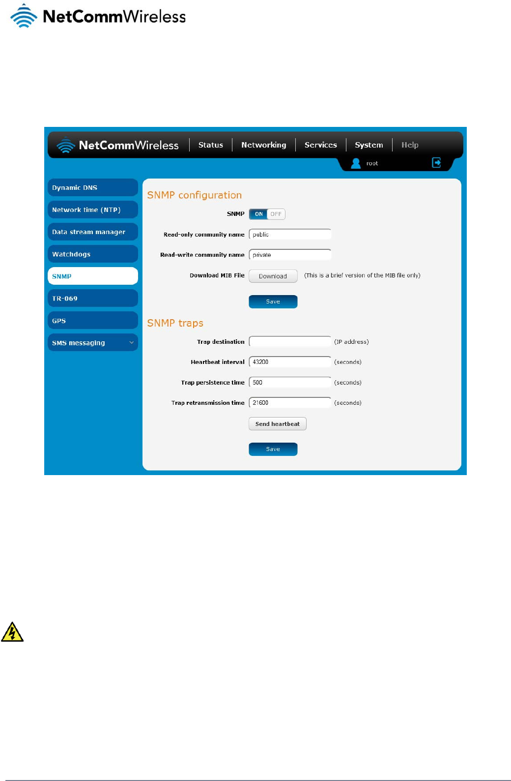
72
NetComm Wireless 3G Light Industrial M2M Route
r
www.netcommwireless.com
SNMP
SNMP configuration
The SNMP page is used to configure the SNMP features of the router.
Figure 77 - SNMP configuration
SNMP (Simple Network Management Protocol) is used to remotely monitor the router for conditions that may warrant administrative attention. It can be used to retrieve information from the router
such as the signal strength, the system time and the interface status.
To configure SNMP:
1. Click the SNMP toggle key to switch it to the ON position.
2. Enter Read-only community name and Read-write community name which are used for client authentication.
Community names are used as a type of security to prevent access to reading and/or writing to the routers configuration. It is recommended that you change the Community names
to something other than the default settings when using this feature.
3. Click the Save button to save any changes to the settings.
The Download button displays the Management information base (MIB) of the router. The MIB displays all the objects of the router that can have their values set or report their status. The MIB is
formatted in the SNMP-related standard RFC1155.
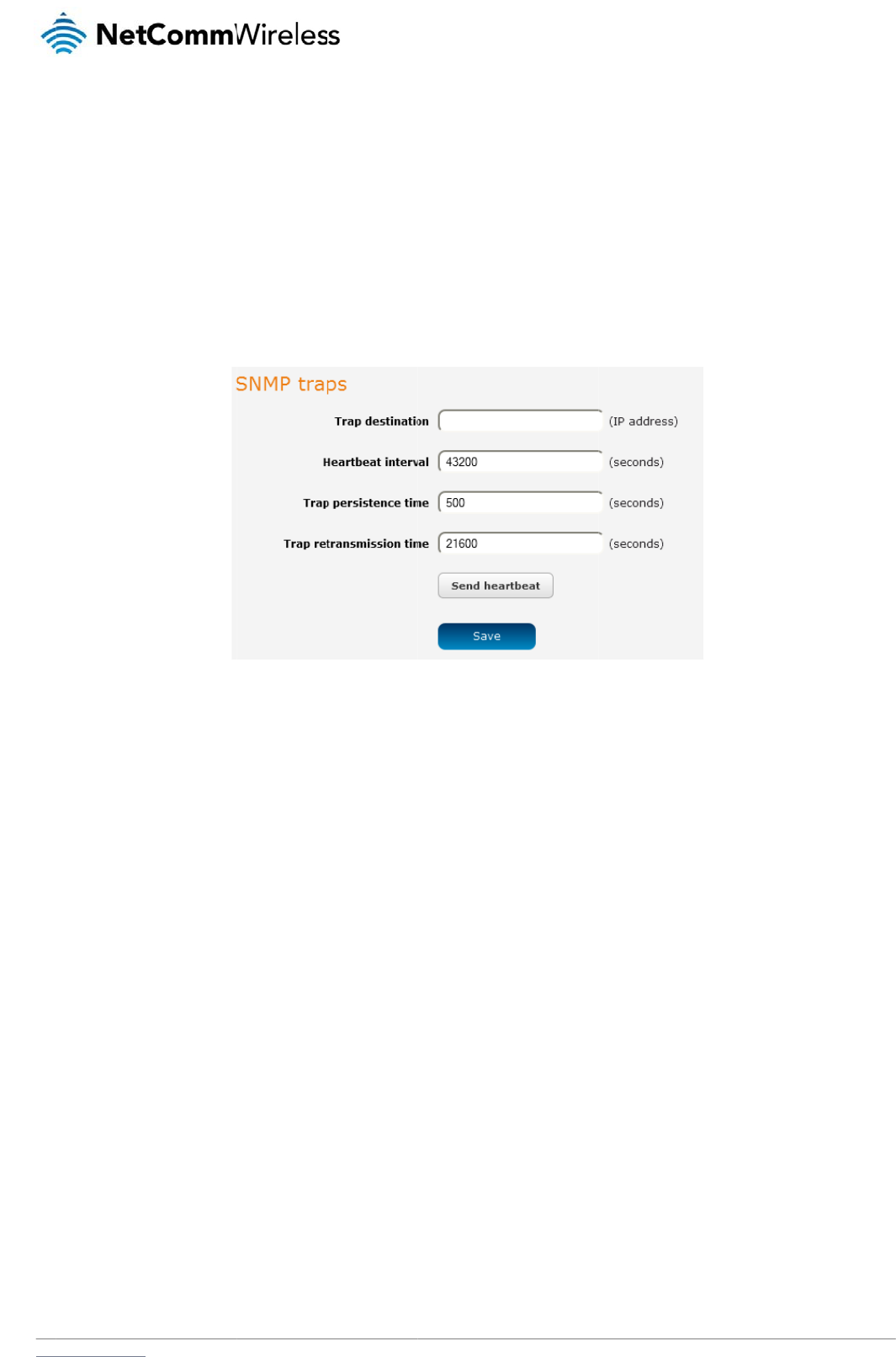
www
S
N
SN
M
whe
t
C
o
To
c
To s
.netcommwireless.com
N
MP traps
M
P traps are messag
e
t
her the link is up or
d
o
nfigurin
g
onfigure SNMP trap
s
1. In the Trap
2. In the Hea
r
3. Use the Tr
a
4. Use the Tr
a
end a manual SNMP
e
s from the router to
d
own.
g
SNMP tr
a
s
:
destination field, en
t
r
tbeat interval field, e
a
p persistence field t
o
a
p retransmission ti
m
P
Heartbeat, click the
the Network Manag
e
a
ps
t
er the IP address to
nter the number of s
e
o
specify the time in
m
e to specify the len
g
Send heartbeat butt
e
ment System sent a
s
which SNMP data is
e
conds between SN
M
seconds that an SN
M
g
th of time in second
s
F
on. When you have f
s
UDP packets. The
y
to be sent.
M
P heartbeats.
M
P trap persists.
s
between SNMP tra
p
F
igure
78 - SNMP tra
p
f
inished configuring
t
y
are often used to n
o
p
retransmissions.
ps
t
he SNMP traps, clic
k
N
e
o
tify the managemen
t
k
the Save button to
s
etComm Wireless 3G
t system of any signi
s
ave the settings.
Light Industrial M2M
R
ficant events such a
s
R
oute
r
73
s
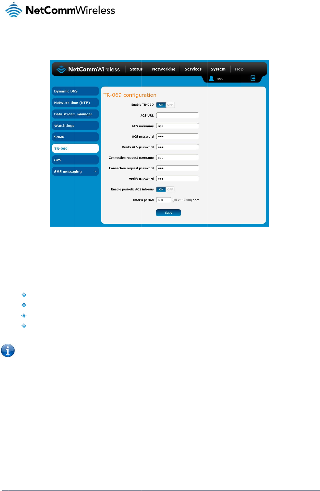
74
Net
C
T
R
To
a
The
con
f
net
w
TR-
0
T
R
To
c
C
omm Wireless 3G Li
g
R
-069
ccess the TR-069 c
o
TR-069 (Technical
R
f
iguration of end-use
r
w
orks to multiple CP
E
0
69 uses a bi-directi
o
Simpl
Enabl
Firm
w
Diag
n
Note: You m
u
R
-069 conf
i
onfigure TR-069:
1. Click the E
n
2. In the ACS
3. Use the A
C
4. In the ACS
5. In the Con
n
6. In the Con
n
7. The inform
messages.
8. In the Infor
m
9. Click the S
a
g
ht Industrial M2M Ro
u
o
nfiguration page, cli
c
R
eport 069) protocol i
r
devices such as cu
E
s.
o
nal SOAP/HTTP-ba
s
ifies the initial config
es easy restoration
o
w
are and software ve
r
n
ostics and monitorin
u
st have your own c
o
fi
guration
nable TR-069 toggle
URL field, enter the
C
S username field to
password and Verif
y
n
ection Request Use
n
ection Request Pas
message acts as a
b
m
Period field, enter
a
ve button to save t
h
u
te
r
c
k the Services men
s a technical specifi
c
stome
r
-premises eq
u
s
ed protocol based
o
uration of a device d
o
f service after a fact
o
r
sion management
g
o
mpatible ACS infras
key to switch it to th
Auto Configuration
S
specify the usernam
y
ACS password fiel
d
rname field, enter th
e
sword and Verify pa
s
b
eacon to inform the
the number of seco
n
h
e settings.
u
item, then select t
h
Figu
re
c
ation also known as
u
ipment (CPE) and
A
n the application lay
e
uring installation
o
ry reset or replace
m
t
ructure to use TR-0
6
e
ON position.
S
erve
r
’s full domain n
e for the Auto Confi
g
d
s, enter the Auto C
o
e
username to use f
o
s
sword fields, enter t
h
ACS of the existenc
e
n
ds between the info
r
h
e TR-069 menu item
r
e
79 - TR-069 confi
gu
CPE WAN Manage
m
A
uto Configuration S
e
er protocol and prov
m
ent of a faulty devic
6
9.In order to acces
s
n
ame or IP address.
g
uration Server.
o
nfiguration Server p
a
o
r the connection req
h
e connection reque
e
of the router. Click
t
r
m messages.
on the left.
gu
ratio
n
m
ent Protocol (CWM
P
e
rvers (ACS). It is pa
r
ides several benefit
s
e
s
and configure the T
a
ssword.
uests.
st password.
t
he Enable periodic
A
P
). It is a f
r
amework f
o
r
ticularly efficient in
a
for the maintenance
R
-069 settings you
m
A
CS informs toggle
k
f
or remote managem
a
pplying configuratio
e
of a field of CPEs:
m
ust be logged into t
h
k
ey to turn on the pe
r
www.netcommwire
l
e
nt and auto-
n updates across
h
e router as the root
r
iodic ACS inform
l
ess.com
user.
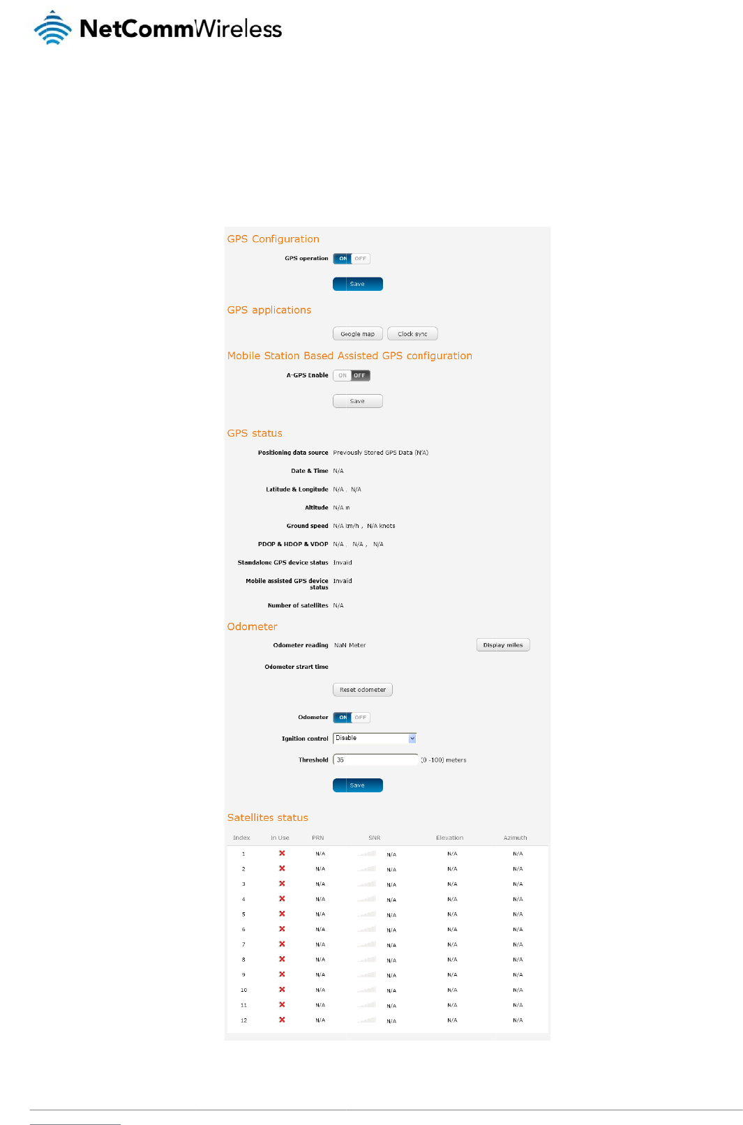
www
G
The
the
c
To u
.netcommwireless.com
G
PS
built-in GPS module
c
urrent location and
t
se the GPS function,
allows you to use lo
c
t
he current GPS sign
set the GPS operati
c
ation-based service
al conditions (positi
o
on toggle key to ON
s, monitor field depl
o
o
n dilution of precisio
and click the Save
b
o
yed hardware or fin
d
o
n (PDOP), horizonta
l
b
utton.
d
your current locati
o
dilution of precision
N
e
o
n. The GPS Status
w
(HDOP) and vertical
etComm Wireless 3G
w
indow provides up t
l dilution of precision
Light Industrial M2M
R
o
date information a
b
(VDOP)) of the rout
e
R
oute
r
75
b
out
er
.
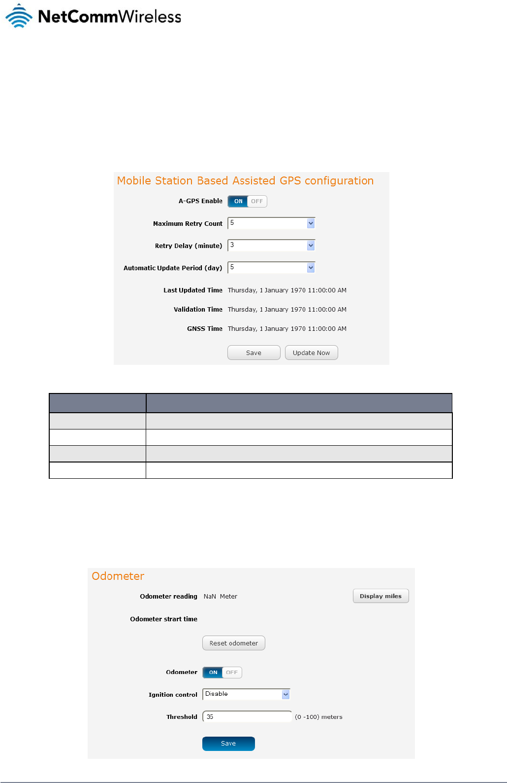
76
NetComm Wireless 3G Light Industrial M2M Route
r
www.netcommwireless.com
The Google map button provides a quick short cut to show your router’s current position on a map and because GPS positioning relies on accurate clock settings to obtain the correct
information about your location, the Clock Sync button allows you to quickly set the router clock to the correct time. This ensures you will always have the correct GPS position information
available.
Mobile Station Based Assisted GPS configuration
If you are not using a dedicated GPS antenna, you may use the nearby mobile base stations to triangulate your position. To do this, set the A-GPS toggle key to the ON position and use the drop
down lists to configure the automatic retry options.
Figure 80 - Mobile Stations Based Assisted GPS configuration options
ITEM DESCRIPTION
A-GPS Enable Enables or disables the mobile station based assisted GPS function.
Maximum Retry Count Sets the maximum number of times the router should attempt to triangulate its position.
Retry delay (minute) Sets the number of minutes the router should wait between attempts to triangulate its position.
Automatic Update Period (day) Sets the number of days that the router should automatically update the A-GPS data. The maximum update period is 7 days.
Table 17 - Mobile Station Based Assisted GPS configuration options
Odometer

www
.netcommwireless.com
N
e
etComm Wireless 3G
Light Industrial M2M
R
R
oute
r
77
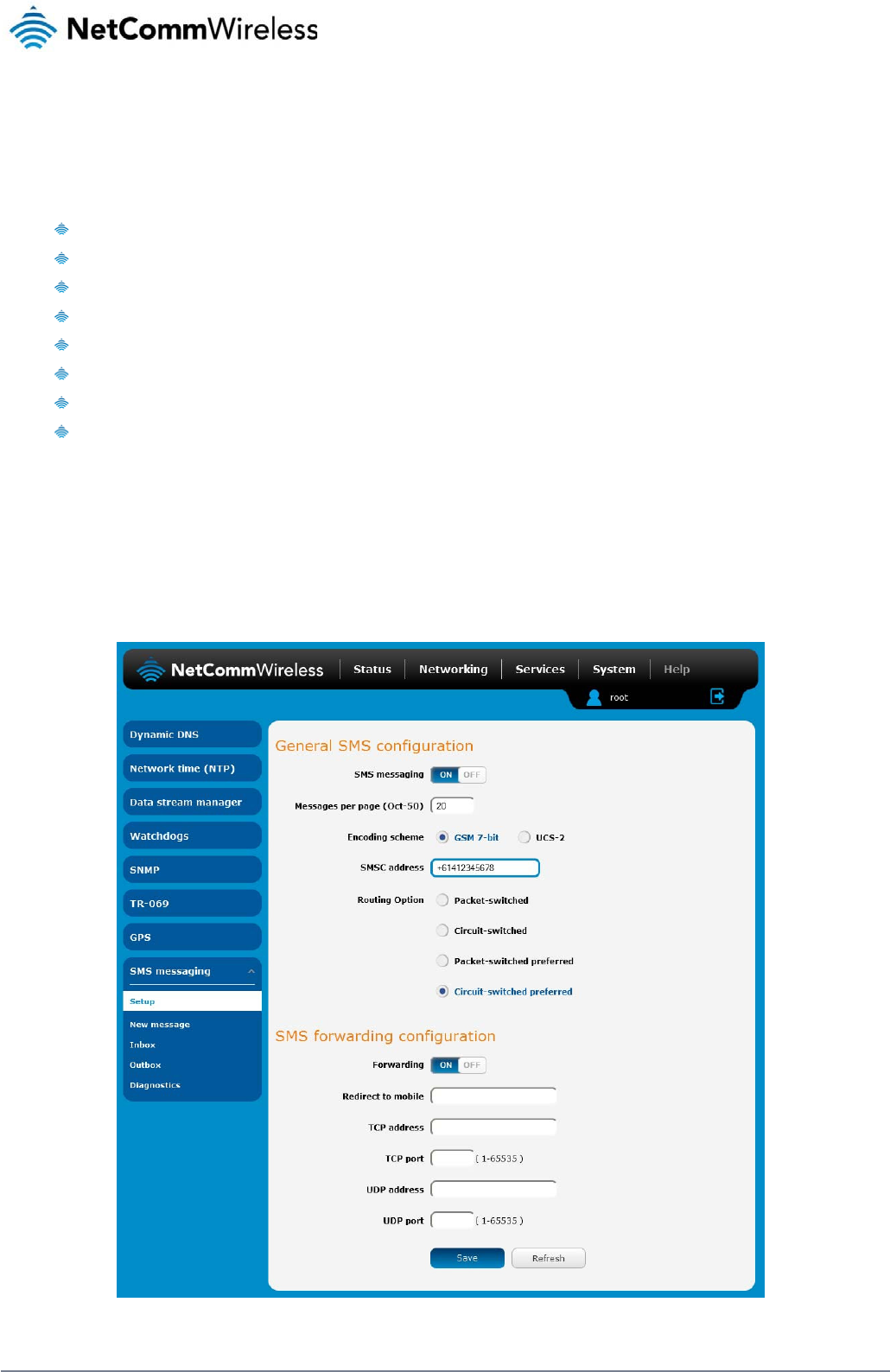
78
NetComm Wireless 3G Light Industrial M2M Route
r
www.netcommwireless.com
SMS messaging
The 3G Light Industrial M2M router offers an advanced SMS feature set, including sending messages, receiving messages, redirecting incoming messages to another destination, as well as
supporting remote commands and diagnostics messages.
Some of the functions supported include:
Ability to send a text message via a CDMA network and store it in permanent storage.
Ability to receive a text message via a CDMA network and store it in permanent storage.
Ability to forward incoming text messages via a CDMA network to another remote destination which may be a TCP/UDP server or other mobile devices.
Ability to receive run-time variables from the device (e.g. uptime) on request via SMS
Ability to change live configuration on the device (e.g. network username) via SMS.
Ability to execute supported commands (e.g. reboot) via SMS
Ability to trigger the 3G Light Industrial M2M router to download and install a firmware upgrade
Ability to trigger the 3G Light Industrial M2M router to download and apply a configuration file
To access the SMS messaging functions of the 3G Light Industrial M2M router, click on the Services menu item from the top menu bar, and then select one of the options under the SMS
messaging section on the left hand menu.
Setup
The Setup page provides the options to enable or disable the SMS messaging functionality and SMS forwarding functionalities of the router. SMS messaging is enabled by default.
Figure 81 - General SMS Configuration

www
S
M
Inc
o
R
e
You
For
E
If so
To
d
R
e
You
mes
The
For
E
If so
“20
0
To
d
.netcommwireless.com
Gen
e
SM
S
Mes
s
Enc
o
SM
S
For
w
Redi
TCP
TCP
UDP
UDP
M
S forwar
d
ming text messages
e
direct to
m
can forward incomi
n
E
xample:
meone sends a text
m
d
isable redirection to
e
direct to
T
can also forward inc
sages.
TCP/UDP address c
a
E
xample:
meone sends a text
m
0
2” at the same time.
d
isable redirection to
OPTION
e
ral SMS configuration
S
messaging
s
ages per page (10-50)
o
ding scheme
S
forwarding configuration
w
arding
rect to mobile
address
port
P
address
P
port
d
ing confi
g
can be redirected t
o
m
obile
n
g text messages to
a
message and Redir
e
a mobile, clear the
R
T
CP / UD
P
c
oming text message
a
n be an IP address
message and TCP
a
a TCP or UDP addr
e
T
o
Th
Th
ch
b
e
T
o
E
n
E
n
Th
E
n
Th
g
uration
o
another mobile dev
a
different destinatio
n
e
ct to mobile is set to
R
edirect to mobile fie
P
address
s to a TCP/UDP bas
e
or domain name. Th
a
ddress is set to “192
e
ss, clear the TCP a
d
ggles the SMS functionalit
y
e number of SMS messag
e
e encoding method used
f
aracters if the message in
c
e
up to 50 characters in len
ggles the SMS forwarding
ter a mobile number as th
e
ter an IP address or doma
e TCP port on which to co
n
ter an IP address or doma
e UDP port on which to co
T
a
bl
ice and/or a TCP/U
D
n
number. This desti
n
“+61412345678”, t
h
ld and click the Sav
e
e
d destination. The T
e
port number rang
e
.168.20.3” and TCP
d
dress and UDP add
r
y of the router on and off.
e
s to display per page. M
u
f
or outbound SMS messag
c
ludes special characters.
n
gth.
function of the router on a
e
destination for forwarde
d
a
in name as the destinatio
n
nnect to the remote destin
a
a
in name as the destinatio
n
o
nnect to the remote destin
bl
e
18 - SMS Setup S
et
D
P message server.
n
ation number can b
h
e text message is st
o
e
button.
T
CP or UDP server c
a
e
is from 1 to 65535.
P
port is set to “2002”
,
ress fields and click
DEFINITION
u
st be a value between 10
es. GSM 7-bit mode perm
i
UCS-2 mode allows the s
e
n
d off.
d
SMS messages.
n
for forwarded SMS mess
a
a
tion.
n
for forwarded SMS mess
a
ation.
et
ting
s
e another mobile ph
o
o
red on the router a
n
a
n be any kind of pu
b
P
lease refer to your
T
,
this text message i
s
the Save button.
N
e
a
nd 50.
ts up to 160 characters p
e
e
nding of Unicode charact
a
ges using TCP.
a
ges using UDP.
o
ne or a 3G router p
h
n
d forwarded to “+61
b
lic or private server
T
CP/UDP based SM
S
stored in the router
a
etComm Wireless 3G
e
r message but drops to 5
0
t
ers and permits a messa
g
h
one number.
412345678” at the s
a
if the server accept
s
S
server configuratio
n
and forwarded to “1
9
Light Industrial M2M
R
0
e to
a
me time.
s
incoming text-base
d
n
for which port to us
9
2.168.20.3” on port
R
oute
r
79
d
e.
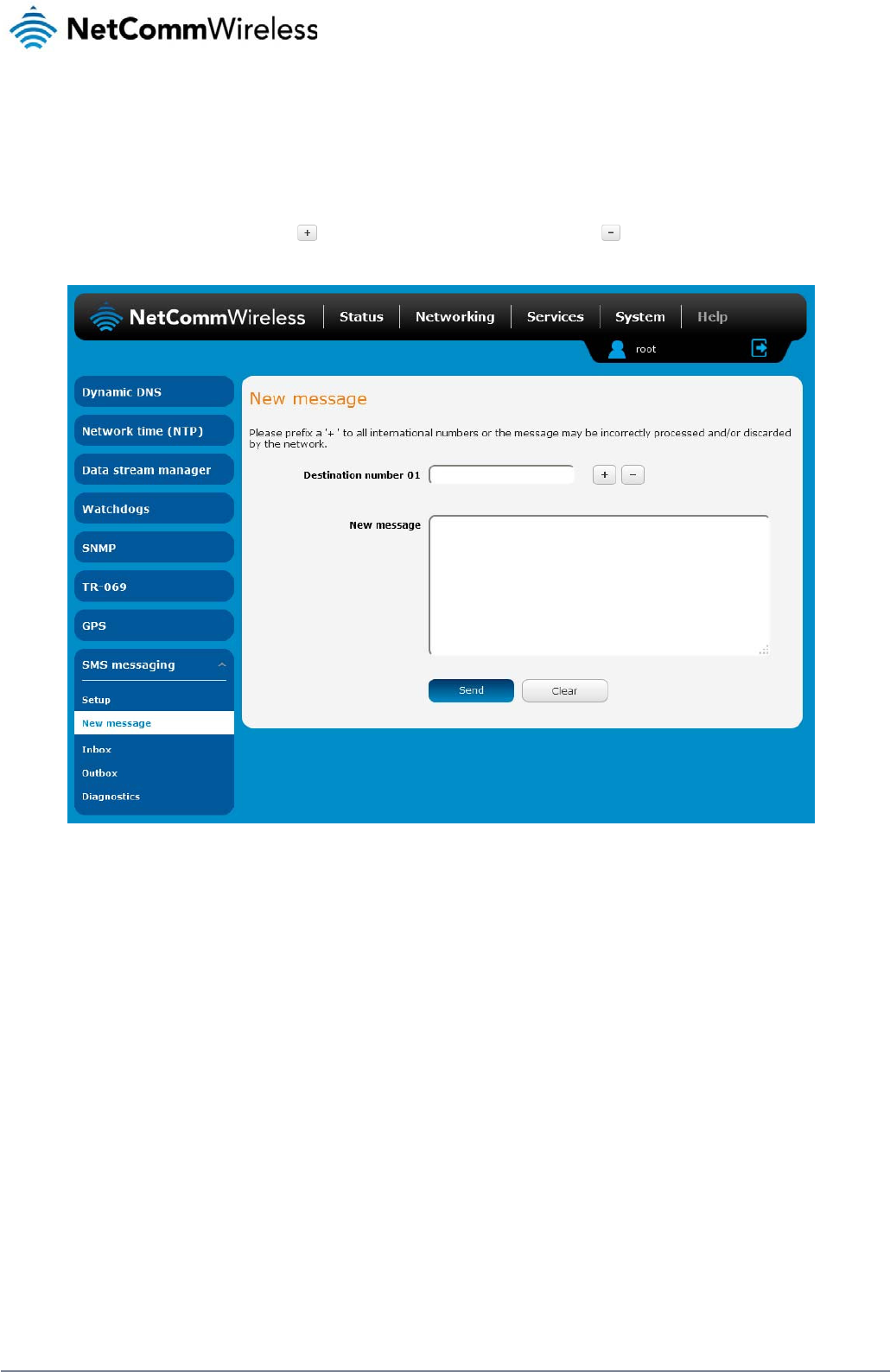
80
NetComm Wireless 3G Light Industrial M2M Route
r
www.netcommwireless.com
New message
The New message page can be used to send SMS text messages to a single or multiple recipients.
A new SMS message can be sent to a maximum of 100 recipients at the same time. After sending the message, the result is displayed next to the destination number as “Success” or “Failure” if
the message failed to send. By default, only one destination number field is displayed. Additional destination numbers may be added one at a time after entering a valid number for the current
destination number field. To add a destination number, click the button and to remove the last destination in the list, click the button.
Figure 82 - SMS - New Message
Destination numbers should begin with the “+” symbol followed by the country calling code. To send a message to a destination number, enter the “+” symbol followed by the country calling
code and then the destination number.
For example:
To send a message to the mobile destination number 0412345678 in Australia (country calling code 61), enter “+61412345678”.
After entering the required recipient numbers, type your SMS message in the New message field. As you type your message, a counter shows how many characters you have entered out of the
total number available for your chosen encoding scheme. When you have finished typing your message and you are ready to send it, click the Send button.
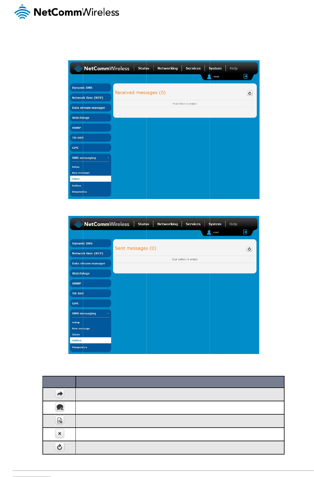
www
In
b
The
.netcommwireless.com
b
ox / Out
b
Inbox displays all re
c
b
ox
c
eived messages th
a
ICON
For
w
Re
p
Ad
d
Del
Re
f
a
t are stored on the
r
w
ard button. Click this but
t
p
ly button. Click this butto
n
d
to White list. Click this b
u
ete button. Click this butto
f
resh button. Click this butt
o
outer while the Outb
o
F
t
on to open a new messag
n
to open a new message
w
tton to add the sender’s m
n
to delete the correspond
o
n to refresh the inbox or
o
T
a
bl
o
x displays all sent
m
Figure 83 - SMS Inb
o
F
igure
84 - SMS Out
b
DESC
e window where you can f
w
indow where you can re
p
m
obile number to the white
d
ing message.
o
utbox to see new messag
b
le
19 - Inbox/Outbo
x
m
essages.
ox
b
o
x
RIPTION
o
rward the corresponding
ly to the sender.
list on the router.
es.
x
icon
s
N
e
message to another recipi
etComm Wireless 3G
i
ent.
Light Industrial M2M
R
R
oute
r
81
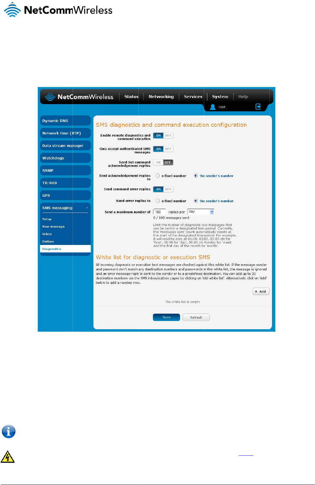
82
Net
C
D
The
stat
u
To
a
S
M
The
En
Ena
b
If re
m
C
omm Wireless 3G Li
g
D
iagno
s
Diagnostics page is
u
s of the router via S
M
ccess the Diagnosti
c
M
S diagno
options on this page
a
ble remote
d
b
les or disables the
r
m
ote diagnostics co
m
Note: It is p
restore nor
m
We highly r
e
g
ht Industrial M2M Ro
u
s
tics
used to configure th
e
M
S commands.
c
s page, click on the
stics and
c
e
are described belo
w
d
iagnostics a
n
r
emote diagnostics f
e
m
mands are found, t
ossible to adjust set
t
m
al operation.
e
commended that y
o
u
te
r
e
SMS diagnostics a
Services menu item
F
c
ommand
w
.
n
d command
e
ature. If this setting
he router executes t
h
t
ings and prevent yo
u
o
u use the white list
a
nd command execu
t
then select the SM
S
F
igure
85 - SMS diag
n
executio
n
execution
is enabled all incomi
h
ose commands. Thi
s
u
r router from functio
a
nd a password whe
n
t
ion configuration. T
h
S
menu on the left an
d
n
ostics and comman
d
n
configur
a
i
ng text messages a
r
s feature is enabled
o
ning correctly using
n
utilising this featur
e
h
is allows you to cha
n
d
finally select Diagn
d
execution configura
ti
a
tion
r
e parsed and tested
by default. All remot
e
remote diagnostics.
e
to prevent unautho
r
n
ge the configuration
o
stics beneath it.
ti
o
n
for remote diagnosti
e
diagnostic comma
n
If this occurs, you wi
ised access. See th
e
n
, perform functions
r
ics commands.
n
ds that are receive
d
i
ll need to perform a
e
White list descripti
o
www.netcommwire
l
r
emotely and check
o
d
are stored in the In
b
f
actory reset in orde
r
o
n for more informati
o
l
ess.com
o
n the
b
ox.
r
to
o
n.

www
O
n
Ena
b
If au
pas
s
If th
e
This
Se
n
The
M2
M
Wa
k
Out
b
This
Se
n
This
If a
f
ack
n
Fi
x
This
Fixe
Se
n
Ena
b
Se
n
Wh
e
Nu
m
to th
Se
n
You
The
The
.netcommwireless.com
n
ly accept aut
h
b
les or disables che
c
thentication is enabl
e
s
word in the white lis
t
e
number does not e
x
is enabled by defau
n
d Set comm
a
3G Light Industrial
M
M
router are optional
w
k
eup command. If di
s
b
ox after they have b
can be useful to det
n
d acknowle
d
option allows you to
f
ixed numbe
r
is sele
c
n
owledgement mess
a
x
ed number t
o
field defines the de
s
d Numbe
r
.
n
d command
b
les or disables the
s
n
d error repl
i
e
n Send Error SMS f
o
m
be
r
. When set to S
M
e number specified i
n
d a maximu
m
can set the maximu
m
router will send a m
a
number of message
s
henticated S
M
c
king the sender’s p
h
e
d, the router will ch
e
t
for the correspondi
n
x
ist in the white list o
lt and it is strongly a
d
a
nd acknowl
e
M
2M router will auto
m
w
ith set commands
a
s
abled, the router do
e
b
een sent.
ermine if a comman
d
d
gement rep
l
specify where to se
n
c
ted, the acknowled
g
a
ge will be sent to th
o
send replie
s
s
tination number to
w
error replie
s
s
ending of an error
m
i
es to
o
r Get/Set/Exec Co
m
M
S Sender Numbe
r
t
h
i
n the following field.
m
number o
f
m
number of ackno
w
a
ximum of 100 replie
s
s
sent is shown belo
w
M
S messages
h
one number agains
t
e
ck if the sender’s n
u
n
g sending numbe
r
.
r the password doe
s
d
vised that you leav
e
e
dgement re
p
m
atically reply to cert
a
a
nd the Wakeup co
m
e
s not send any ack
n
d
was received and
e
l
ies to
n
d acknowledgment
g
ement message will
e number that the S
M
s
to
w
hich error message
s
s
m
essage resulting fro
m
mand is set to ON,
t
h
e router will reply to
w
ledgement and erro
r
s
by default.
w
the options. The to
t
the allowed sender
u
mber exists in the
w
If they match, the di
a
not match, the rout
e
e
this feature enable
d
p
lies
a
in types of comman
m
mand. This option E
n
owledgement after
e
e
xecuted by the rout
e
messages after the
e
be sent to the numb
M
S diagnostic or co
m
s
are sent after the e
x
m the execution of a
his option is used to
the originating num
b
r
messages sent wh
e
t
al transmitted mess
a
white list for incomi
n
w
hite list. If it exists, t
h
a
gnostic or comman
d
e
r does not execute t
d
to maintain securit
y
ds received, such a
s
nables or disables s
e
e
xecution of a set c
o
e
r. This option is dis
a
e
xecution of a set, o
r
b
er defined in the Fix
e
m
mand message ori
g
x
ecution of a get, se
t
get, set, or exec co
m
specify where the e
r
b
er of the SMS diagn
e
n an SMS diagnosti
c
a
ge count resets aft
e
g diagnostics and c
o
h
e router then check
s
d
is executed.
he incoming diagno
s
y
.
s
get commands, or
e
e
nding an acknowle
d
o
mmand or SMS Wa
k
a
bled by default.
r
exec command.
e
d number to send r
e
g
inated from. The de
f
, or exec command.
m
mand.
A
ll error rep
l
r
ror SMS is sent. Use
ostic or command.
W
c
or command is exe
e
r a reboot or at the
b
N
e
o
mmand execution
S
s
the password (if co
n
s
tic or command in t
h
e
xecute commands.
d
gment message aft
e
eup command.
A
ll a
c
e
plies to field. If the
s
f
ault setting is to use
This field is only dis
p
ies are stored in the
the radio buttons to
W
hen set to Fixed Nu
cuted. The maximu
m
b
eginning of the time
etComm Wireless 3G
S
MS messages.
nfigured) in the inco
m
h
e SMS message.
However replies fro
m
e
r execution of a set
cknowledgment repl
s
ender’s numbe
r
is
s
the sender’s numbe
p
layed when Send
E
Outbox after they h
a
select either Fixed
N
mbe
r
the router will
s
m
limit can be set pe
r
frame specified.
Light Industrial M2M
R
m
ing message again
m
the 3G Light Indus
t
command or SMS
ies are stored in the
s
elected, the
r
.
E
rror SMS to is set to
a
ve been sent.
N
umbe
r
or SMS Sen
d
s
end the error mess
a
r
hour, day, week or
m
R
oute
r
83
st the
t
rial
d
er
a
ges
m
onth.
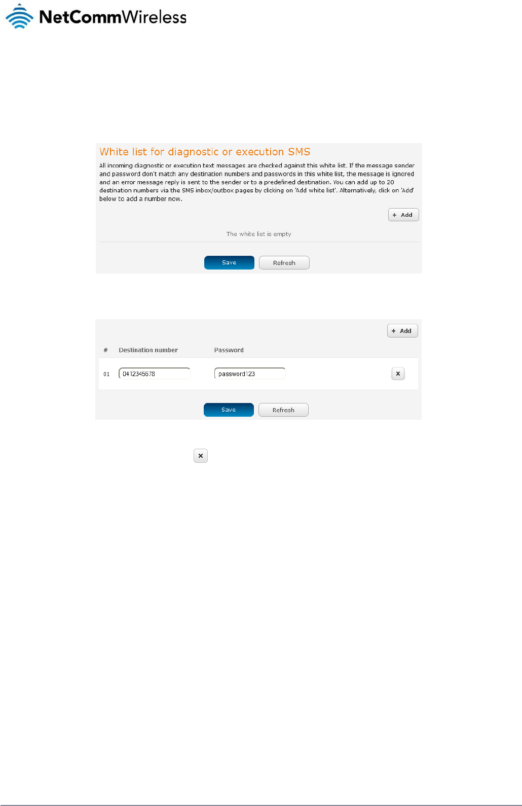
84
NetComm Wireless 3G Light Industrial M2M Route
r
www.netcommwireless.com
White List for diagnostic or execution SMS
The white list is a list of mobile numbers that you can create which are considered “friendly” to the router. If Only accept authenticated SMS messages is enabled in the diagnostics section, the
router will compare the mobile number of all incoming diagnostic and command messages against this white list to determine whether the diagnostic or command should be executed. You may
optionally configure a password for each number to give an additional level of security. When a password is specified for a number, the SMS diagnostic or command message is parsed for the
password and will only be executed if the number and password match.
Figure 86 - White list for diagnostic or execution SMS
A maximum of 20 numbers can be stored on the router in the white list. To add a number to the white list, click the “+Add” button.
Figure 87 – Adding a number to the SMS white list
The White List numbers and passwords can be cleared by pressing the button to the right of each entry. To add a number to the white list, enter it in the Destination number field and
optionally define a password in the Password field. When you have finished adding numbers click the Save button to save the entries.

www
S
e
Foll
o
T
y
The
r
If au
The
S
M
The
com
valu
e
.netcommwireless.com
e
ndin
g
o
w the steps below t
o
1. Navigate t
o
2. Confirm th
a
3. If you wish
for diagno
s
you wish t
o
4. If you woul
d
Note: An alt
e
button next
t
5. Click the S
a
y
pes of S
M
r
e are three types of
c
exec
u
get V
A
set V
A
thentication is enabl
e
PASS
PASS
PASS
following are some
e
pass
w
get rs
set a
p
M
S ackno
w
router automatically
mand acknowledge
m
e
is incorrect, for ex
a
g
an S
M
o
configure the route
r
o
the Services > SM
S
a
t the Enable remote
to have the router o
n
s
tic or execution SM
S
o
also configure a pa
s
d
prefer to accept S
M
e
rnative method of a
d
t
o the message whi
c
a
ve button.
M
S diagno
s
c
ommands that can
u
te COMMAND
A
RIABLE
A
RIABLE=VALUE
e
d, each command
m
WORD execute CO
M
WORD get VARIAB
L
WORD set VARIABL
e
xamples of SMS dia
g
w
ord6657 execute re
s
si
p
n1=testAPNvalue
w
ledgmen
replies to get comm
a
m
ent replies toggle k
e
a
mple, due to missp
e
M
S Dia
g
r
to optionally accep
t
S
messaging > Diag
n
diagnostics and co
m
n
ly accept command
S
messages section,
s
sword, enter the pa
s
M
S diagnostic comm
d
ding a number to t
h
c
h corresponds to th
e
s
tic comm
a
be sent; execute, ge
t
m
ust be preceded b
y
M
MAND
L
E
E=VALUE
g
nostic commands:
boo
t
t replies
a
nds with a value an
d
e
y is set to ON. If th
e
e
lling.
g
nostic
t
SMS diagnostic co
m
n
ostics page
m
mand execution to
g
s
from authenticated
click the +Add butto
s
sword in the Passw
o
ands from any send
e
h
e white list is to sen
d
e
sender’s number.
a
nds
t
and set. The basic
y
the password:
d
execute command
s
e
Send command err
o
Com
m
m
mands only from a
u
g
gle key is set to the
senders, ensure th
a
n and enter the sen
d
w
ord field correspond
e
r, set the Only acce
d
an SMS message t
syntax is as follows:
s
with either a succe
s
or replies toggle key
m
and
u
thenticated sender
s
ON position. If it is s
e
a
t Only accept authe
n
d
er’s number in inter
n
ing to the destinatio
n
pt authenticated SM
S
o
the router, navigat
e
s
s or error response.
is set to ON, the rou
N
e
and learn how to se
e
t to OFF click the to
n
ticated SMS messa
g
n
ational format into t
h
n
number.
S
messages toggle
k
e
to Services > SMS
Set commands will
o
t
er will send a reply i
f
etComm Wireless 3G
e
nd SMS diagnostic
c
o
ggle key to switch it
ges is set to the ON
p
h
e Destination numb
e
k
ey to the OFF positi
o
messaging > Inbox
only be responded t
o
i
f the command is c
o
Light Industrial M2M
R
c
ommands to the rou
to the ON position.
p
osition. In the Whit
e
er
field that appears.
o
n.
a
nd then click the
o
if the Send Set
o
rrect but a variable
o
R
oute
r
85
ter.
e
list
If
o
r

86
NetComm Wireless 3G Light Industrial M2M Route
r
www.netcommwireless.com
SMS command format
Generic Format for reading variables:
get VARIABLE
PASSWORD get VARIABLE
Generic Format for writing to variables:
set VARIABLE=VALUE
PASSWORD set VARIABLE=VALUE
Generic Format for executing a command:
Execute COMMAND
PASSWORD execute COMMAND
Replies
Upon receipt of a successfully formatted, authenticated (if required) command, the gateway will reply to the SMS in the following format:
TYPE SMS CONTENTS NOTES
get command “VARIABLE=VALUE”
set command “Successfully set VARIABLE to VALUE” Only sent if the acknowledgment message function is enabled
execute command “Successfully executed command COMMAND”
Table 20 - SMS Diagnostic Command Syntax
Where “VARIABLE” is the name of the value to be read
Where “VARIABLE (x)” is the name of another value to be read
Where “VALUE” is the content to be written to the “VARIABLE”
Where “COMMAND” is a supported command to be executed by the device (e.g. reboot)
Where “PASSWORD” is the password (if configured) for the corresponding sender number specified in the White List
Multiple commands can be sent in the same message, if separated by a semicolon.
For Example:
get VARIABLE1; get VARIABLE2; get VARIABLE3
PASSWORD get VARIABLE1; get VARIABLE2
set VARIABLE=VALUE1 ; set VARIABLE2=VALUE2
PASSWORD set VARIABLE1=VALUE1; set VARIABLE2=VALUE2; set VARIABLE3=VALUE3
If required, values can also be bound by an apostrophe, double apostrophe or back tick.
For Example:
“set VARIABLE=’VALUE’”
“set VARIABLE=”VALUE””
“set VARIABLE=`VALUE`”
“get VARIABLE”

www
.netcommwireless.com
N
e
etComm Wireless 3G
Light Industrial M2M
R
R
oute
r
87

88
Net
C
A p
a
“PA
S
“PA
S
If th
e
reb
o
For
E
“PA
S
“PA
S
Li
s
A lis
“pd
p
prof
i
C
omm Wireless 3G Li
g
a
ssword (if required),
S
SWORD get Variabl
S
SWORD set VARIA
B
e
command sent incl
o
ot with this same pa
s
E
xample:
S
SWORD execute re
b
S
SWORD execute re
b
Note: Comm
s
t of valid
t of valid commands
p
cycle”, “pdpdown”
i
le list page of the W
e
#
1 re
2 p
d
3 p
d
4 p
d
5 fa
c
6 d
o
g
ht Industrial M2M Ro
u
,
only needs to be s
p
e1”; “get VARIABLE
2
B
LE1=VALUE1”; “se
t
udes the “reboot” c
o
s
sword.
boot; getVariable1”;
boot; PASSWORD g
e
ands, variables and
comman
d
which can be used
i
and “pdpup” comm
a
e
b-UI.
COMMAN
D
boot
d
pcycle
d
pdown
d
pup
c
torydefaults
o
wnload
u
te
r
p
ecified once per SM
2
”
t
VARIABLE2=VALU
E
o
mmand and has alr
e
“get VARABLE2”
e
t Variable1”; “get V
A
values are case sen
s
d
s
i
n conjunction with t
h
a
nds can have a pro
D
NAME
S, but can be prefix
e
E
2”
e
ady passed the whi
t
A
RABLE2”
s
itive.
h
e execute comman
d
f
ile number suffix ‘x’
a
Immediately performs a
Disconnects (if connect
e
specified profile in cas
e
profile number is select
e
Disconnects the PDP. If
profile number is select
e
profile.
Reconnects the PDP. If
selected, the router trie
s
executing the comman
d
Performs a factory rese
t
Performs a download a
n
If the file is a firmware i
m
location is specified im
m
If the file is a .tar.gz file,
If the file is a .pdf, the r
o
on the Web-UI.
Note: If your download
U
ftp://username:passwor
d
Note: Authenticated FT
P
ftp://username:passwor
d
Table 21 - Li
st
e
d to each comman
d
t
e list password che
c
d
are listed below:
added. Without the
s
soft reboot.
t
ed) and reconnects the d
a
e
the profile is active. If no
p
e
d and there is no currentl
f
a profile number is select
e
e
d, try to disconnect the c
u
a profile number is select
e
s
to connect to the last act
i
d
. The router reports an er
r
t
on the router.
n
d install of a Firmware U
p
m
age as in the case of a .
c
m
ediately after the comma
n
the router will apply the fil
o
uter will assume this is a
u
U
RL includes any space c
d@serveraddress/director
y
P
addresses may be used
d@serveraddress/director
y
st
of Valid SMS diagn
o
d
if desired.
c
k, the device keeps
s
uffix specified, the c
DESC
R
a
ta connection. If a profile
n
p
rofile number is selected,
y
activated profile.
e
d in the command, the ro
u
u
rrent active profile. Repo
r
e
d in the command, the ro
u
ve profile. The gateway wi
r
or if no profile number is s
e
grade (.cdi), Config File (.
t
c
di file, the router will appl
y
n
d and may be from an H
T
e as a configuration file u
p
u
ser guide document and
s
h
aracters, please encode
t
y
%20with%20spaces/filen
a
following the format as de
f
y
/filename.cdi
o
stic command
s
this password and e
x
ommand operates a
g
R
IPTION
n
umber is selected in the
c
try to disconnect/reconne
c
u
ter tries to disconnect the
t
s an error if no profile nu
m
u
ter tries to connect with th
e
l
l check the currently activ
a
e
lected and there is no sto
ar.gz) or a help document
the recovery image first a
n
T
TP or FTP source URL.
date for the device and re
b
s
ave it to the router and m
a
t
hese prior to transmission
a
me.cdi
f
ined in RFC1738, for exa
m
e
xecutes the remaini
n
gainst the default pr
o
c
ommand, try to disconne
c
ct the current active profil
e
e
specified profile in case t
m
ber is selected and there
h
e specified profile. If no p
r
ated profile and disconne
c
o
red last active profile num
t
(.pdf) file.
nd then the main firmware
boot afterwards.
a
ke the file available for vi
e
according to RFC1738, f
o
m
ple:
www.netcommwire
l
n
g command line aft
e
o
file configured on t
h
c
t/reconnect the
e
. Reports an error if no
h
e profile is active. If no
is no currently activated
r
ofile number is
c
t this profile before
ber.
image. The download
e
wing via the help menu
o
r example:
l
ess.com
e
r the
h
e

www
The
vari
a
0
2
3
4
5
6
7
8
9
10
11
S
M
The
.netcommwireless.com
following table lists
v
a
bles are read from
o
#
link.profile.1.en
link.profile.1.ap
link.profile.1.us
e
link.profile.1.pa
link.profile.1.au
t
link.profile.1.ipl
o
link.profile.1.st
a
link.profile.1.us
e
link.profile.1.pa
link.profile.1.au
t
link.profile.1.ipl
o
wwan.0.radio.i
n
wwan.0.meid
statistics.usag
e
statistics.usag
e
/proc/uptime
wwan.0.system
M
S diagno
examples below de
m
D
Send SMS to cha
n
Send SMS to cha
n
Send SMS to cha
n
authentication
Send SMS to reb
o
Send SMS to che
c
Send SMS to che
c
v
alid variables where
o
r written to for the s
p
RDB VARIABLE N
A
able
p
n
e
r
a
ss
th_type
o
cal
a
tus
e
r
a
ss
th_type
o
cal
n
formation.signal_strength
e
_current
e
_current
_network_status.current_
b
stics exa
m
m
onstrate various co
m
DESCRIPTION
n
ge the data connection u
s
n
ge the data connection p
a
n
ge the data connection
o
ot
c
k the WAN IP address
c
k the mobile signal stren
g
“x” is a profile num
b
p
ecified profile num
b
A
ME
b
and
m
ples
m
binations of suppo
r
AU
T
s
ername
Not requir
e
Required
a
ssword
Not requir
e
Required
Not requir
e
Required
Not requir
e
Required
Not requir
e
Required
g
th
Not requir
e
Required
b
er (1-6). If no profile
er (‘x’).
SMS VARI
A
BLE
profile
username
password
authtype
wanip
rssi
meid
usage
wanuptime
deviceuptime
band
Table 22 -
r
ted commands. Thi
s
T
HENTICATION
e
d
e
d
e
d
e
d
e
d
e
d
is specified, variabl
e
NAME READ/
W
E
RW
RW
RW
RW
R
R
R
R
R
R
R
List of SMS diagnos
ti
s
is not an exhaustiv
e
set username=’NetCo
PASSWORD set user
n
set password= `NetC
o
PASSWORD set pass
w
set authtype= ‘pap’
PASSWORD set auth
t
execute reboot
PASSWORD execute
r
get wanip
PASSWORD get wani
p
get rssi
PASSWORD get rssi
e
s are
r
ead from or
w
W
RIT DESC
R
Profile
3G username
3G password
3G Authentica
t
WAN IP addre
s
3G signal stre
n
MEID number
3G data usage
session
Up time of cur
r
Device up tim
e
Current Frequ
e
band
ti
cs
v
ariables
e
list and serves as a
mm’
n
ame= ”NetComm”
o
mm`
w
ord= `NetComm`
t
ype = pap
r
eboot
p
N
e
w
ritten to for the curre
R
IPTION
Re
a
(pr
o
1,a
t
Wri
t
(at
d
atd
#
Gu
e
Gu
e
ion type ”p
a
s
s 20
2
gth -65
0x
0
of current “R
x
byt
e
e
nt 3G session 1 d
1 d
ncy channel & CH
n example of possib
i
INPUT EXAMPLE
etComm Wireless 3G
e
nt active profile. If a
EXA
M
a
d:
o
file no,atd#xxx,user,pass
,
a
td#777,username,passwo
r
i
te:
d
#xxx, user, pass,auth)
d
#777,username,password
est, could also return “null
”
est, could also return “null
”
a
p” or”chap”
2
.44.185.111
5
dBm
0
0A1000021D003BB
x
500 bytes, Tx 1024 bytes
t
e, Total 0 byte” when wwa
d
ays 02:30:12 or 0 days 00
d
ays 02:30:12
H
:425 PCS-B Band
ilities only.
Light Industrial M2M
R
profile is specified,
M
PLE VALUE
,
auth,iplocal,status)
r
d, chap,202.44.185.111,u
”
”
, Total 1524 bytes” or “Rx
0
n down
:00:00 when wwan down
R
oute
r
89
p
0
byte, Tx 0

90
NetComm Wireless 3G Light Industrial M2M Route
r
www.netcommwireless.com
Send SMS to check the MEID number
Not required get meid
Required PASSWORD get meid
Send SMS to check the current band
Not required get band
Required PASSWORD get band
Send SMS to Disconnect (if connected) and
reconnect the data connection
Not required execute pdpcycle
Required PASSWORD execute pdpcycle
Send SMS to disconnect the data connection
Not required execute pdpdown
Required PASSWORD execute pdpdown
Send SMS to connect the data connection
Not required execute pdpup
Required PASSWORD execute pdpup
Send multiple get command
Not required get wanip; get rssi
Required PASSWORD get wanip; get rssi
Send multiple set command
Not required set ssh.genkeys=1; set username=test; set auth=pap
Required PASSWORD set ssh.genkeys=1; set username=test; set auth=pap
Send SMS to reset to factory default settings
Not required execute factorydefaults
Required PASSWORD execute factorydefaults
Send SMS to retrieve status of router
Not required get status
Required PASSWORD get status
Send SMS to retrieve the history of the session,
including start time, end time and total data usage
Not required get sessionhistory
Required PASSWORD get sessionhistory
Send SMS to configure the router to send syslog to a
remote syslog server
Not required set syslogserver
Required PASSWORD set syslogserver
Send SMS to wake up the router, turn on the default
gateway and trigger the ‘connect on demand’ profile
if in waiting state.
Not required execute wakeup
Required PASSWORD execute wakeup
Send SMS to perform firmware upgrade when
firmware is located on HTTP server
Not required
execute download http://download.com:8080/firmware_image.cdi
execute download http://download.com:8080/firmware_image_r.cdi
Required
PASSWORD execute download http://download.com:8080/firmware_image.cdi
PASSWORD execute download http://download.com:8080/firmware_image_r.cdi
Send SMS to perform firmware upgrade when
firmware is located on FTP server
Not required
execute download ftp://username:password@download.com/firmware_image.cdi
execute download ftp://username:password@ download.com/firmware_image_r.cdi
Required
PASSWORD execute download ftp://username:password@ download.com/firmware_image.cdi
PASSWORD execute download ftp://username:password@ download.com/firmware_image_r.cdi
Send SMS to turn off PPPoE
Not required set pppoe=0
Required PASSWORD set pppoe=0
Send SMS to turn on PPPoE and set dialstring and
service name
Not required set pppoe=1,atd#777, Test
Required PASSWORD set pppoe=1,atd#777, Test
Send SMS to retrieve the PPPoE status, currently
configured dial string and service name
Not required get pppoe
Required PASSWORD get pppoe
Send SMS to set the LED mode timeout to 10 minutes
Not required set ledmode=10
Required PASSWORD set ledmode=10
Send SMS to retrieve the current LED mode
Not required get ledmode
Required PASSWORD get ledmode
Retrieve current SSH protocol
Not required get ssh.proto
Required PASSWORD get ssh.proto

www
.netcommwireless.com
Select SSH proto
c
Retrieve passwor
d
Enable/disable p
a
Generate set of p
u
Clear client publi
c
Retrieve the MEI
D
c
ol
d
authentication status
a
ssword authentication on
h
u
blic/private keys on the h
o
c
keys stored on host
D
of the router
Not requir
e
Required
Not requir
e
Required
h
ost
Not requir
e
Required
o
st
Not requir
e
Required
Not requir
e
Required
Not requir
e
Required
Table 23 - S
M
e
d
e
d
e
d
e
d
e
d
e
d
M
S diagnostics exam
p
set ssh.proto=1
PASSWORD set ssh.
p
get ssh.passauth
PASSWORD get.ssh.
p
set ssh.passauth=1 o
r
PASSWORD set ssh.
p
execute ssh.genkeys
PASSWORD execute
s
execute ssh.clearkey
s
PASSWORD execute
s
get MEID
PASSWORD get MEI
D
p
le command
s
p
roto=1
p
assauth
r
set ssh.passauth=0
p
assauth=1 or PASSWOR
D
s
sh.genkeys
s
s
sh.clearkeys
D
N
e
set ssh.passauth=0
etComm Wireless 3G
Light Industrial M2M
R
R
oute
r
91
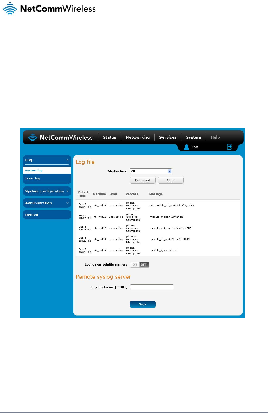
92
NetComm Wireless 3G Light Industrial M2M Route
r
www.netcommwireless.com
System
Log
The Log pages are used to display or download the System log and IPSec logs on the router.
System log
The System Log enables you to troubleshoot any issues you may be experiencing with your 3G Light Industrial M2M router. To access the System Log page, click on the System menu. The
System Log is displayed.
Figure 88 - System log file
Log file
Use the Display level drop-down list to select a message level to be displayed. The message levels are described in the table below.
To download the System log for offline viewing, right-click the Download button and choose Save as.. to save the file. To clear the System log, click the Clear button. The downloaded log file is in
Linux text format with carriage return (CR) only at the end of a line, therefore in order to be displayed correctly with new lines shown, it is recommended to use a text file viewer which displays
this format correctly (e.g. Notepad++).
Log data is stored in RAM and therefore, when the unit loses power or is rebooted, it will lose any log information stored in RAM. To ensure that log information is accessible between reboots of
the router there are two options:
1. Enable the Log to file option

www.netcommwireless.com
2. Use a rem
o
o
te syslog serve
r
N
e
etComm Wireless 3G
Light Industrial M2M
R
R
oute
r
93
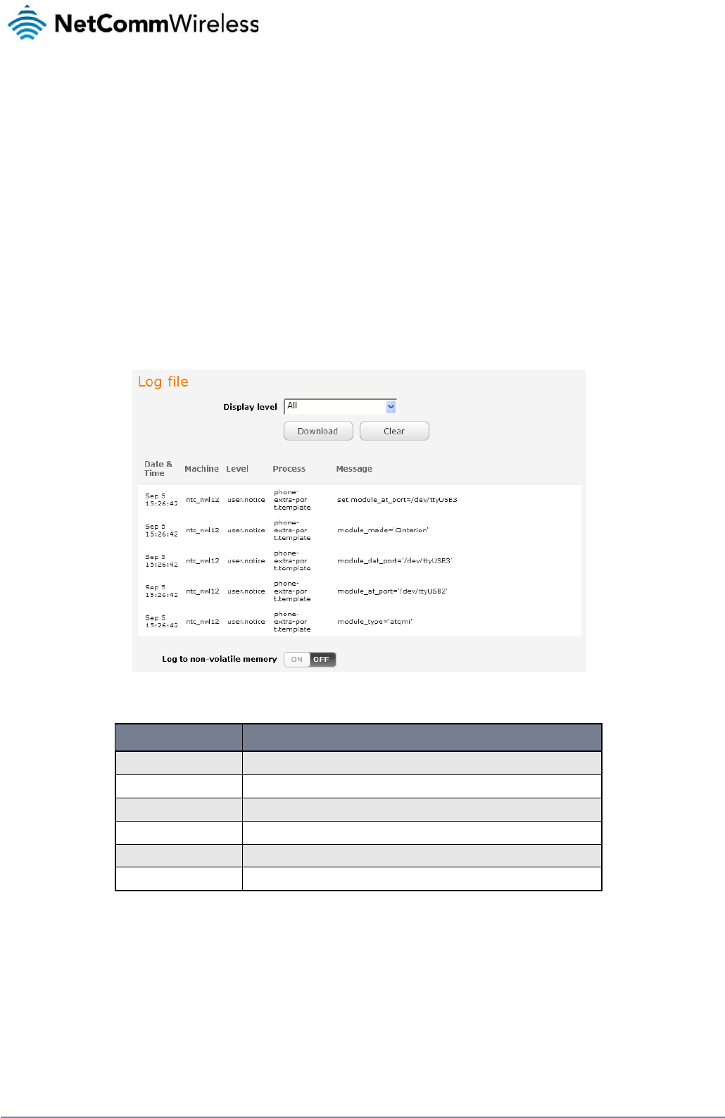
94
NetComm Wireless 3G Light Industrial M2M Route
r
www.netcommwireless.com
Enable the log to file option
When the router is configured to log to a file, the log data is stored in flash memory, making it accessible after a reboot of the router. Up to 512kb of log data will be stored before it is overwritten
by new log data. Flash memory has a finite number of program-erase operations that it may perform to the blocks of memory. While this number of program-erase operations is quite large, we
recommend that you do not enable this option for anything other than debugging to avoid excessive wear on the memory.
Use a remote syslog server
The router can be configured to output log data to a remote syslog server. This is an application running on a remote computer which accepts and displays the log data. Most syslog servers can
also save the log data to a file on the computer on which it is running allowing you to ensure that no log data is lost between reboots.
To configure the 3G Light Industrial M2M Router to output log data to a remote syslog server:
1. Click on the System menu from the top menu bar. The System log item is displayed.
2. Under the Remote syslog server section, enter the IP address or hostname of the syslog server in the IP / Hostname [:PORT] field. You can also specify the port number after the
IP or hostname by entering a semi-colon and then the port number e.g. 192.168.1.102:514. If you do not specify a port number, the router will use the default UDP port 514.
3. Click the Save button to save the configuration.
Figure 89 - System log
ITEM DEFINITION
All Display all system log messages.
Debug Show extended system log messages with full debugging level details.
Info Show informational messages only.
Notice Show normal system logging information.
Warning Show warning messages only.
Error Show error condition messages only.
Table 24 - System log detail levels

www
IP
S
The
Use
be
d
To
d
.netcommwireless.com
S
ec log
IPSec log section pr
o
the Log level drop d
d
isconnected as a c
h
d
ownload the IPSec l
o
o
vides the ability for
own list to specify th
h
ange in logging lev
e
o
g, click the Downlo
a
you to download the
e type of detail you
w
e
l requires the IPSec
a
d IPSec log button
a
log for the IPSec VP
w
ant to capture in th
e
s
ervice to be restart
e
a
nd you will be prom
P
N function. This can
Figure 90 - IPSec lo
g
e
log and then click t
e
d.
m
pted to save the file.
assist in troublesho
o
g
h
e Save button. Wh
e
N
e
o
ting any problems y
o
n you change the lo
g
etComm Wireless 3G
o
u may have with th
e
g
ging level, any acti
v
Light Industrial M2M
R
e
IPSec VPN.
v
e IPSec VPN tunnel
s
R
oute
r
95
s
will
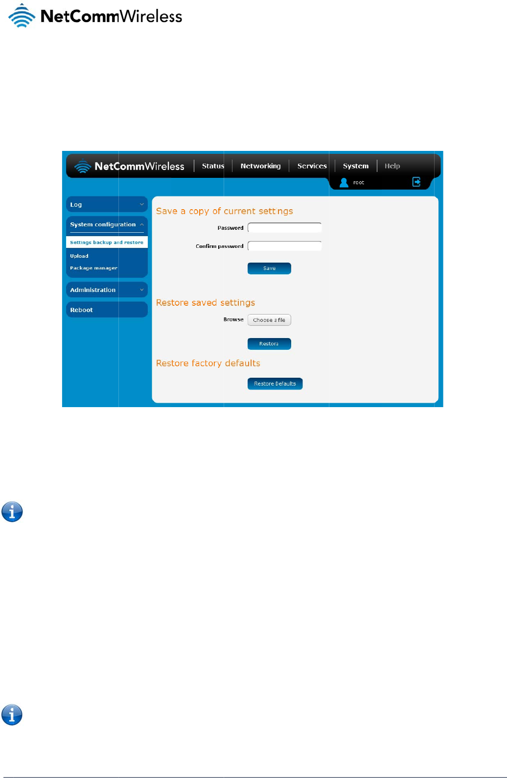
96
Net
C
S
y
S
e
The
inte
r
with
Ba
c
Log
If yo
you
r
Re
s
Re
s
Clic
k
rest
o
C
omm Wireless 3G Li
g
y
stem
C
e
ttings ba
c
settings backup / re
s
r
face as root usi
n
your desired setting
s
c
k up your ro
in to the web config
u
u want to password
p
r
files, just click on S
a
Note: The fol
l
It is NOT p
o
You may c
h
s
tore your b
a
1. In the web
2. From the
R
3. Click Rest
o
s
toring the r
o
k
the Restore Defaul
t
o
ring of factory defa
u
Note: All cur
r
root and
d
g
ht Industrial M2M Ro
u
C
onfi
g
c
kup and
r
s
tore page is used t
o
n
g the password a
d
s
, backing them up t
o
uter’s config
u
u
ration interface, clic
p
rotect your backup
a
ve. The router will t
h
l
owing conditions ap
o
ssible to edit the co
h
ange the name of t
h
a
ckup config
u
configuration interfa
c
R
estore saved setting
o
re to copy the settin
g
o
uter’s factor
y
t
s button to restore t
h
u
lts, click OK.
r
ent settings on the r
o
d
efault password a
d
u
te
r
g
uratio
n
r
estore
o
backup or restore t
h
d
min. The backup
o a file and then rest
u
ration
k on the System me
n
configuration files, e
h
en prompt you to se
ply:-
ntents of the file do
w
h
e file if you wish but
u
ratio
n
c
e click on the Syste
s section, click on B
r
g
s to the new 3G Li
g
y
default conf
i
h
e factory default co
n
o
uter will be lost whe
d
min will be confi
g
n
h
e router’s configura
t
/
restore functions c
a
oring that file to mult
i
Figure 9
1
n
u and select Setting
nter your password i
lect a location to sa
v
w
nloaded; if you mod
i
the filename extensi
o
m menu and select
S
r
owse or Choose a fi
ht Industrial M2M ro
u
i
guration
n
figuration. The rout
e
n
performing a resto
r
g
ured.
tion or to reset it to f
a
a
n be used to easily
c
iple 3G Light Industr
91
– Settings backup
a
g
s backup and restor
e
n the fields under S
a
v
e the settings file.
ify the contents of th
e
on must remain as “.
S
ettings backup and
i
le and select the ba
c
u
te
r
. The router will
a
e
r asks you to confir
m
re of factory default
s
a
ctory defaults. In or
d
c
onfigure a large nu
m
ial M2M routers.
a
nd restor
e
e
.
a
ve a copy of curren
t
e
configuration file in
cfg”
restore.
c
kup configuration fil
a
pply these settings
a
m
that you wish to re
s
s
ettings. The device
d
er to view the settin
g
m
ber of 3G Light Ind
u
t
settings and click o
n
any way you will not
e on your computer.
a
nd inform you it will
r
s
tore factory default
s
I
P address will chan
g
g
s page you must b
e
ustrial M2M router b
y
n Save. If you don’t
w
t
be able to restore it
reboot - click on OK
.
s
ettings. If you wish t
g
e to 192.168.1.1 an
www.netcommwire
l
e
logged into the we
b
y
configuring one ro
u
w
ant to password pr
o
later.
.
o
continue with the
d
the default userna
m
l
ess.com
b
user
u
ter
o
tect
m
e
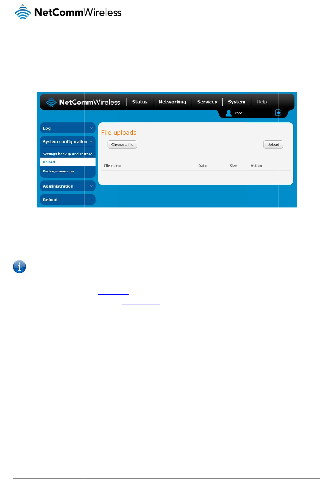
www
U
p
To
a
The
they
For
m
U
p
The
To u
.netcommwireless.com
p
load
ccess the Upload p
a
Upload page allows
can also be installe
d
m
ore information on
a
p
dating th
e
firmware update pro
Note: In ord
e
pdate the 3G Light I
n
1. Power on t
h
2. Log in to t
h
3. Select the
S
4. Under the
F
ntc_nwl12
_
5. Click the U
a
ge, click on the Sys
t
you to upload firmw
a
d
from this page. PD
F
a
pplication develop
m
e Firmwa
r
cess involves first u
p
e
r to perform an upd
a
n
dustrial M2M Route
h
e router as describ
e
h
e router with the roo
t
S
ystem item from th
e
F
ile uploads section,
_
x.xx.xx.x_r.cdi while
pload button. The fir
m
t
em menu, then Syst
a
re files, HTTPS certi
F
files, such as this
u
m
ent, contact NetCo
m
r
e
p
dating the recovery
a
te, you must be log
g
r’s firmware:
e
d in the Installing th
e
t
user account (See
t
e
top menu bar, sele
c
click the Browse bu
t
the main system fir
m
m
ware image is uplo
a
e
m Configuration an
d
ficates or user creat
e
ser guide may also
b
m
m Wireless about o
F
image firmware and
g
ed into the router wi
t
e
route
r
section.
t
he Advanced config
c
t the System config
u
t
ton. Locate the reco
m
ware image is nam
e
a
ded to the storage
o
d then Upload.
e
d application pack
a
b
e uploaded for acc
e
ur Softwa
r
e Develop
F
igure
92 - Upload p
ag
then updating the m
th the root manager
uration section for d
e
u
ration item from the
o
very firmware image
e
d ntc_nwl12_x.xx.x
x
o
n the router.
a
ges to the 3G Light
e
ss on the router’s h
e
ment Kit.
age
ain firmware image.
a
ccount (see the
A
d
v
e
tails)
menu on the left an
d
file on your comput
e
x
.x.cdi.
N
e
I
ndustrial M2M route
r
e
lp page.
v
anced configuratio
n
d
then select the Upl
o
e
r and click Open. T
h
etComm Wireless 3G
r. When firmwa
r
e file
n
section for more d
e
o
ad menu item.
h
e recovery image is
Light Industrial M2M
R
s have been upload
e
e
tails).
named
R
oute
r
97
e
d,
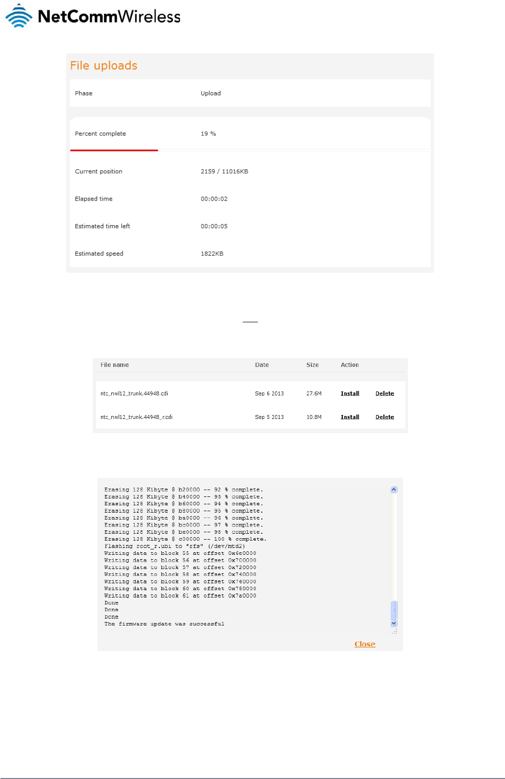
98
NetComm Wireless 3G Light Industrial M2M Route
r
www.netcommwireless.com
Figure 93 - File upload
6. Repeat steps 4 and 5 for the main system firmware image.
7. The uploaded firmware images are listed in the Uploaded files section. Click the Install link next to the recovery image to begin installing the recovery firmware image and then click
OK on the confirmation window that appears.
Figure 94 - Uploaded files
8. The recovery firmware image is flashed and when it is complete, the router displays “The firmware update was successful” and returns to the main Upload screen.
Figure 95 - Recovery firmware flash process
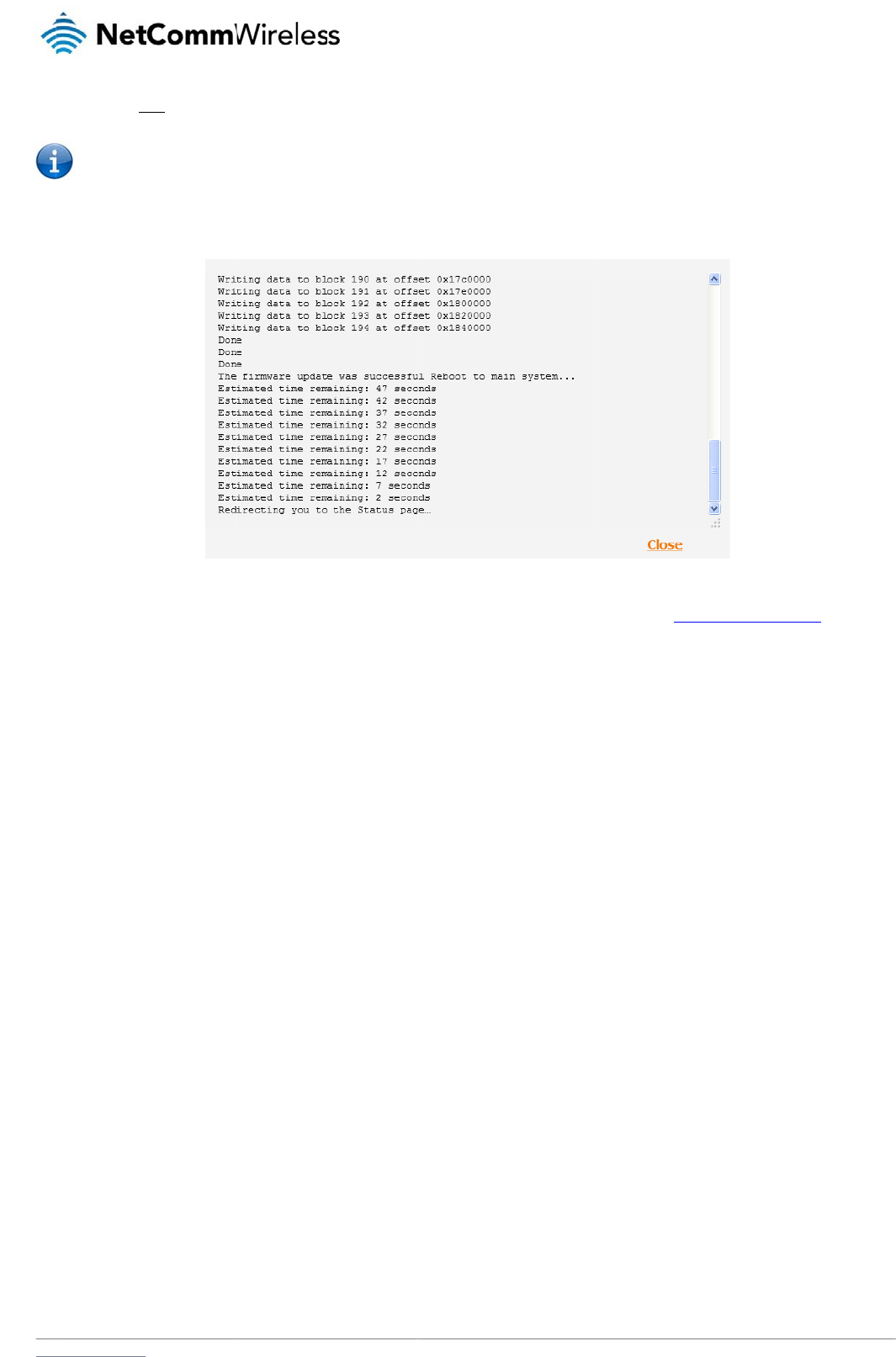
www
.netcommwireless.com
9. Click the I
n
Note: Do not
10. The install
a
11. Hold down
information
n
stall link to the right
o
remove the power
w
a
tion is complete wh
e
the reset button on
t
.
o
f the main firmware
w
hen the router’s LE
D
e
n the countdown re
a
t
he router for 15-20 s
image you uploade
d
D
s are flashing as thi
s
a
ches zero. The rout
e
Figure 96
-
e
conds to reboot an
d
d
and then click OK
t
s
is when the firmwar
e
r attempts to redire
c
-
– Installing main fir
m
d
restore the factory
t
o confirm that you w
a
e
update is in proce
s
c
t you to the Status
p
m
ware imag
e
default settings of th
N
e
a
nt to continue with t
s
s.
age.
e
router. See the Re
s
etComm Wireless 3G
t
he installation.
s
toring factory defau
Light Industrial M2M
R
l
t settings section fo
r
R
oute
r
99
r
more

100
NetComm Wireless 3G Light Industrial M2M Route
r
www.netcommwireless.com
Package manager
The Package Manager page is used to provide details of any user installed packages on the router and allow them to be uninstalled.
For more information on application development, contact NetComm Wireless about our Software Development Kit.
Figure 97 – Software applications manager
The Application name, Version number of the application, the architecture type and time of installation are all displayed. Clicking the Package details link will display a pop-up window with
further details of the package.
To uninstall any software applications, click the Uninstall link.
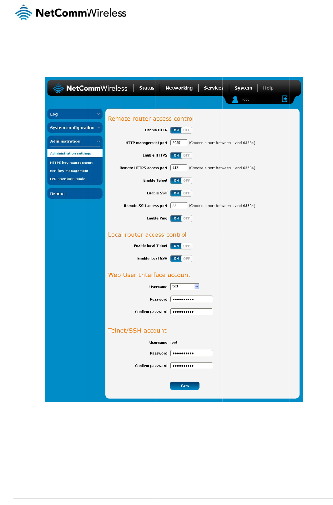
www
A
d
To
a
The
.netcommwireless.com
d
ministrat
i
ccess the Administr
a
Administration settin
i
on settin
g
a
tion Settings page,
c
gs page is used to e
g
s
c
lick on the System
m
nable or disable pro
t
m
enu then the Admi
n
t
ocols used for remo
t
Figu
r
n
istration menu on th
e
te access and confi
g
u
re
98 -
A
dministratio
n
e
left and then click
o
g
ure the passwords
f
n
pag
e
N
e
o
n Administration Se
t
o
r the user accounts
etComm Wireless 3G
t
tings.
s
used to log in to th
e
Light Industrial M2M
R
e
router.
R
oute
r
101
102
Net
C
To
a
C
omm Wireless 3G Li
g
ccess the router’s c
o
1. Open a ne
w
Note: You ca
n
2. Enter the u
s
Note: To perf
o
account.
OPTION
Remote router access c
o
Enable HTTP
HTTP management port
Enable HTTPS
Remote HTTPS access
p
Enable Telnet
Enable SSH
Remote SSH Access Por
t
Enable Ping
Web User Interface acc
o
Username
Password
Confirm password
Telnet/SSH account
Username
Password
Confirm password
g
ht Industrial M2M Ro
u
o
nfiguration pages r
e
w
browser window a
n
n
find the router’s W
A
s
ername and passw
o
o
rm functions like Fir
m
o
ntrol
Enable or dis
a
Enter a port n
u
Enable or dis
a
p
ort Enter a port n
u
Enable or dis
a
Enable or dis
a
r
t Enter the port
Enable or dis
a
o
unt
Use the drop
Enter the desi
Re-enter the
d
Displays the
T
Enter the desi
Re-enter the
d
u
te
r
e
motely:
n
d navigate to the W
A
A
N IP address by clic
o
rd to login to the ro
u
m
ware upgrade, dev
i
a
ble remote HTTP access
t
u
mber between 1 and 655
a
ble remote HTTPS acces
s
u
mber between 1 and 655
a
ble remote telnet (comma
a
ble Secure Shell on the r
o
number for remote SSH a
c
a
ble remote ping respons
e
down list to select the root
red web user interface pa
s
d
esired web user interface
T
elnet/SSH.username. This
red Telnet/SSH password.
d
esired Telnet/SSH passw
Table 25 -
Ad
A
N IP address and
a
king on the “Status”
m
u
ter and click Log in.
i
ce configuration ba
c
t
o the router. You can also
3
4 to use when accessing
s
to the router using a sec
u
3
4 to use when accessing
nd line) access to the rout
e
uter.
c
cess. Must be a port num
s on the WWAN connectio
or admin account to chan
g
s
sword.
password.
may not be changed.
o
rd.
Ad
ministration
config
u
a
ssigned port numb
e
menu. The WWAN I
P
c
kup and to restore
a
D
set the port you would lik
e
the router remotely.
u
re connection.
the router remotely over a
er.
ber between 1 and 65534
.
o
n.
g
e its web user interface
p
u
ratio
n
options
r of the router, for ex
P
field in the WWAN
C
a
nd reset the router t
o
D
EFINITION
e
remote HTTP access to b
secure HTTPS connectio
n
.
p
assword.
a
mple http://123.209
C
onnection Status se
o
factory defaults, yo
e
available on.
.
9
.130.249:8080
e
ction shows the rout
e
o
u must be logged in
www.netcommwire
l
e
r’s WAN IP address
with the root manag
e
l
ess.com
.
e
r
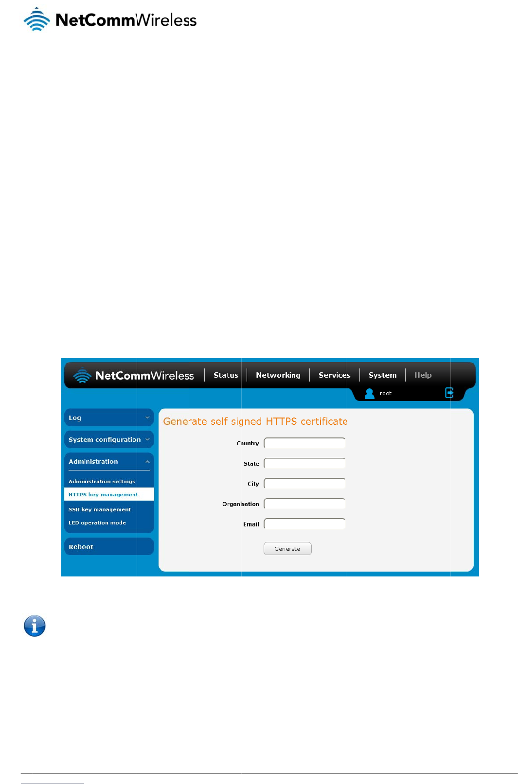
www
H
W
HTT
site
t
of c
e
it ca
The
r
The
info
r
info
r
Eac
h
gen
e
auth
G
e
To
g
.netcommwireless.com
H
TTPS
k
W
hat is HT
T
P Secure or HTTPS i
s
t
o which it is connec
t
e
rtificates issued by
t
n verify the authenti
c
r
e are two main diffe
r
1. HTTPS use
2. Over an H
T
encryption is achiev
e
r
mation (encrypt it),
m
r
mation and can be
d
h
3G Light Industrial
e
rating your own uni
q
ority and then uploa
d
e
nerating
g
enerate your own se
1. Click the S
y
2. Enter the c
e
Note: The
C
k
ey ma
T
P Secure
?
s
the use of the HTT
P
t
ed. This is especiall
y
t
rusted certificate au
t
c
ity of the site using
a
r
ences between how
s port 443 while HT
T
T
TPS connection, all
d
e
d through the use
o
m
aking the informati
o
d
istributed freely. Th
e
M2M router contain
s
q
ue key. Additionally
d
those certificates t
o
your own
e
lf-signed certificate:
y
stem item from the
t
e
rtificate details usin
C
ountry field must co
n
nage
m
?
P
protocol over an S
S
y
important when yo
u
t
horities such as Ver
i
a
built-in list of truste
d
HTTPS and HTTP c
o
T
P uses port 80 by d
e
d
ata sent and receiv
o
f a pair of public an
d
o
n secure and visible
e
private key is used
s
a self-signed digital
, you may use third
p
o
the router.
self-sign
e
t
op menu bar, then
A
g the appropriate fie
n
tain a code for the
d
m
ent
S
L/TLS protocol. It is
u
wish to have a sec
u
Sign. When a web b
d
certificate authoriti
e
o
nnections work:
e
fault.
ed is encrypted with
d
private keys on bot
h
only to those who h
a
to decrypt informati
o
certificate which is i
d
p
arty software to gen
e
e
d certific
a
A
dministration from t
h
lds. Each field must
b
Figure 99 -
Ge
d
esired country from
used primarily to pr
o
u
re connection over
a
rowser makes a con
n
e
s.
SSL while over an H
h
sides of the conne
c
a
ve the correspondi
n
o
n and must be secr
e
dentical on all 3G Li
g
erate your own self-
s
a
te
h
e side menu bar an
d
be completed in ord
e
Ge
nerate self signed
HT
the list below.
o
tect against eavesd
r
a
public network su
c
n
ection attempt to a
s
TTP connection, all
d
c
tion. In cryptograph
n
g key to recover (d
e
e
t by its owner.
g
ht Industrial M2M r
o
s
igned digital certific
a
d
then HTTPS key
m
e
r to generate a cert
i
T
TPS certificat
e
N
e
r
opping of communi
c
h as the internet. HT
T
s
ecured web site, a
d
d
ata is sent unencry
p
y, a key refe
r
s to a n
u
crypt) the informatio
n
o
uters. For a greater l
a
te or purchase a si
g
anagement.
ficate.
etComm Wireless 3G
c
ation between a we
b
TPS connections ar
e
d
igital certificate is s
p
ted.
umerical value used
n. The public key is
u
level of security, the
g
ned certificate from
Light Industrial M2M
R
b
browser and the w
e
e
secured through th
e
e
nt to the browser s
o
by an algorithm to a
u
sed to encrypt
router also supports
a trusted certificate
R
oute
r
103
e
b
e
use
o
that
lter

104
NetComm Wireless 3G Light Industrial M2M Route
r
www.netcommwireless.com
CODE COUNTRY CODE COUNTRY CODE
COUNTRY CODE
COUNTRY
AX Åland Islands E
R
Eritrea LS
Lesotho
S
A
Saudi Arabia
AD Andorra ES Spain LT
Lithuania
SB
Solomon Islands
AE United Arab Emirates
ET Ethiopia LU
Luxembourg
SC
Seychelles
AF Afghanistan FI Finland L
V
Latvia
SE
Sweden
AG Antigua and Barbuda
FJ Fiji L
Y
Libya
SG
Singapore
AI Anguilla FK Falkland Islands (Malvinas)
M
A
Morocco
SH
St. Helena
AL Albania FM Micronesia
MC
Monaco
SI
Slovenia
AM Armenia FO Faroe Islands
MD
Moldova
SJ
Svalbard and Jan Mayen Islands
AN Netherlands Antilles F
R
France ME
Montenegro
SK
Slovak Republic
AO Angola FX France, Metropolitan
MG
Madagascar
SL
Sierra Leone
AQ Antarctica G
A
Gabon MH
Marshall Islands
SM
San Marino
A
R
Argentina GB Great Britain (UK)
MK
Macedonia
SN
Senegal
AS American Samoa GD Grenada ML
Mali
S
R
Suriname
AT Austria GE Georgia MM
Myanmar
ST
Sao Tome and Principe
AU Australia GF French Guiana
MN
Mongolia
SU
USSR (former)
AW Aruba GG Guernsey MO
Macau
S
V
El Salvador
AZ Azerbaijan GH Ghana MP
Northern Mariana Islands
SZ
Swaziland
B
A
Bosnia and Herzegovina
GI Gibraltar MQ
Martinique
TC
Turks and Caicos Islands
BB Barbados GL Greenland
M
R
Mauritania
TD
Chad
BD Bangladesh GM Gambia MS
Montserrat
TF
French Southern Territories
BE Belgium GN Guinea MT
Malta
TG
Togo
BF Burkina Faso GP Guadeloupe
MU
Mauritius
TH
Thailand
BG Bulgaria GQ Equatorial Guinea
M
V
Maldives
TJ
Tajikistan
BH Bahrain G
R
Greece MW
Malawi
TK
Tokelau
BI Burundi GS S. Georgia and S. Sandwich Isls.
MX
Mexico
TM
Turkmenistan
BJ Benin GT Guatemala
M
Y
Malaysia
TN
Tunisia
BM Bermuda GU Guam MZ
Mozambique
TO
Tonga
BN Brunei Darussalam G
W
Guinea-Bissau
N
A
Namibia
TP
East Timor
BO Bolivia G
Y
Guyana NC
New Caledonia
T
R
Turkey
B
R
Brazil HK Hong Kong
NE
Niger
TT
Trinidad and Tobago
BS Bahamas HM Heard and McDonald Islands
NF
Norfolk Island
T
V
Tuvalu
BT Bhutan HN Honduras NG
Nigeria
T
W
Taiwan
BV Bouvet Island H
R
Croatia (Hrvatska)
NI
Nicaragua
TZ
Tanzania
BW Botswana HT Haiti NL
Netherlands
U
A
Ukraine
BZ Belize HU Hungary NO
Norway
UG
Uganda
C
A
Canada ID Indonesia NP
Nepal
UM
US Minor Outlying Islands
CC Cocos (Keeling) Islands
IE Ireland N
R
Nauru
US
United States
CF Central African Republic
IL Israel NT
Neutral Zone
UY
Uruguay
CH Switzerland IM Isle of Man
NU
Niue
UZ
Uzbekistan
CI Cote D'Ivoire (Ivory Coast) IN India NZ
New Zealand (Aotearoa)
V
A
Vatican City State (Holy See)
CK Cook Islands IO British Indian Ocean Territory
OM
Oman
VC
Saint Vincent and the Grenadines
CL Chile IS Iceland P
A
Panama
VE
Venezuela
CM Cameroon IT Italy PE
Peru
VG
Virgin Islands (British)
CN China JE Jersey PF
French Polynesia
VI
Virgin Islands (U.S.)
CO Colombia JM Jamaica PG
Papua New Guinea
VN
Viet Nam
C
R
Costa Rica JO Jordan PH
Philippines
VU
Vanuatu
CS Czechoslovakia (former)
JP Japan PK
Pakistan
WF
Wallis and Futuna Islands
CV Cape Verde KE Kenya PL
Poland
WS
Samoa
CX Christmas Island KG Kyrgyzstan
PM
St. Pierre and Miquelon
YE
Yemen
CY Cyprus KH Cambodia
PN
Pitcairn
YT
Mayotte
CZ Czech Republic KI Kiribati P
R
Puerto Rico
Z
A
South Africa
DE Germany KM Comoros PS
Palestinian Territory
ZM
Zambia
DJ Djibouti KN Saint Kitts and Nevis
PT
Portugal
COM
US Commercial
DK Denmark K
R
Korea (South)
PW
Palau
EDU
US Educational
DM Dominica KW Kuwait P
Y
Paraguay
GO
V
US Government
DO Dominican Republic KY Cayman Islands
Q
A
Qatar
INT
International
DZ Algeria KZ Kazakhstan
RE
Reunion
MIL
US Military
EC Ecuador L
A
Laos RO
Romania
NET
Network
EE Estonia LC Saint Lucia
RS
Serbia
ORG
Non-Profit Organization
EG Egypt LI Liechtenstein
RU
Russian Federation
A
RP
A
Old style Arpanet
EH Western Sahara LK Sri Lanka RW
Rwanda

www
.netcommwireless.com
N
e
etComm Wireless 3G
Light Industrial M2M
R
R
oute
r
105

106
NetComm Wireless 3G Light Industrial M2M Route
r
www.netcommwireless.com
3. When you have entered all the required details, press the Generate button. The certificate takes several minutes to generate. When the certificate has been generated, you are
informed that it has been successfully generated and installed. The web server on the router restarts and you are logged out of the router. Click OK to be taken back to the login
screen.
Figure 100 - New certificate successfully generated message
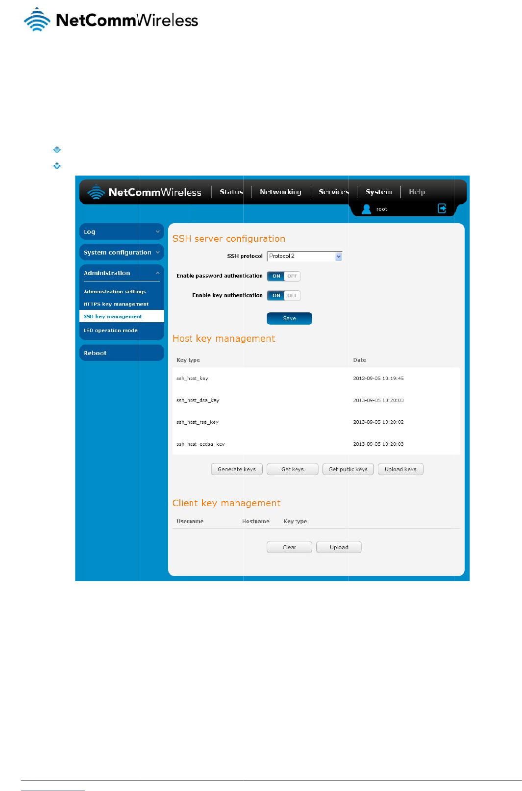
www
S
S
Sec
u
bet
w
SSH
S
S
To
c
.netcommwireless.com
S
H Ke
y
u
re Shell (SSH) is U
N
w
een machines. It w
a
uses RSA public ke
y
Use
a
Use
a
S
H Server
C
onfigure the SSH se
r
1. Use the SS
2. Select the
t
authentica
t
3. Click the S
a
y
Mana
g
N
IX-based command
a
s designed as a rep
y
cryptography for b
o
a
utomatically genera
t
a
manually generate
d
C
onfigur
a
r
ver settings:
H Protocol drop do
w
t
ypes of authenticati
o
t
ion methods on but
y
a
ve button to confir
m
g
eme
n
interface and netwo
lacement for Telnet
a
o
th connection and
a
t
ed public-private ke
y
d
public-private key
p
a
tion
w
n list to select the p
r
o
n you want to use b
y
y
ou may not turn the
m
m
your settings.
n
t
r
k protocol used to g
a
nd other insecure r
e
a
uthentication. Two
c
y
pairs to encrypt th
e
p
air to perform the a
u
Figure
1
r
otocol that you want
y
clicking the Enable
m
both off.
g
ain secure access t
o
e
mote shell protocols
c
ommon ways of usi
n
e
network connectio
n
u
thentication and all
o
1
0
1
- SSH Server Co
nf
to use. Protocol 2 is
e
password authentic
o
a remote compute
r
which send informa
t
n
g SSH are:
n
and then use pass
w
o
w users or program
s
f
iguratio
n
more recent and is
c
ation and Enable ke
y
N
e
,
execute command
s
t
ion, including pass
w
w
ord authentication t
o
s
to log in without usi
n
c
onsidered more sec
y
authentication togg
etComm Wireless 3G
s
on a remote machi
n
w
ords, as plain text.
o
log on.
ng a password.
c
ure.
g
le keys on or off. No
t
Light Industrial M2M
R
n
e or to transfer files
t
e that you may have
R
oute
r
107
both
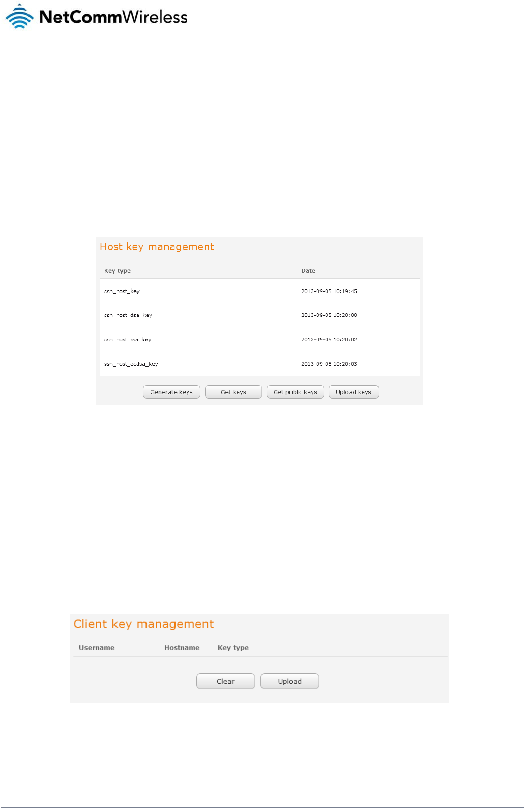
108
NetComm Wireless 3G Light Industrial M2M Route
r
www.netcommwireless.com
Host key management
SSH keys provide a means of identification using public key cryptography and challenge response authentication. This means that a secure connection can be established without transmitting a
password, thereby greatly reducing the threat of someone eavesdropping and guessing the correct credentials.
SSH Keys always come in pairs with one being a public key and the other a private key. The public key may be shared with any server to which you want to connect. When a connection request
is made, the server uses the public key to encrypt a challenge (a coded message) to which the correct response must be given. Only the private key can decrypt this challenge and produce the
correct response. For this reason, the private key should not be shared with those who you do not wish to give authorization.
The Host key management section displays the current public keys on the router and their date and timestamp. These public keys are provided in different formats, including DSA, RSA and
ECDSA. Each format has advantages and disadvantages in terms of signature generation speed, validation speed and encryption/decryption speed. There are also compatibility concerns to
consider with older clients when using ECDSA, for example.
Generating new keys
The complete set of keys can be re-generated by selecting the Generate keys button. This key generation process takes approximately 30 seconds to complete.
Downloading keys
The Get keys button allows you to download the complete set of public and private keys while the Get public keys button will download only the set of public keys.
Uploading your own key files
Click the Upload keys button to upload your own public key to the router.
Client key management
The Client Key Management section is used for uploading the public key file of clients. To upload a client public key, click the Upload button, browse to the file and click Open.
When the file is uploaded, it is examined for validity. If the key file is not a valid public key, it will not be uploaded.
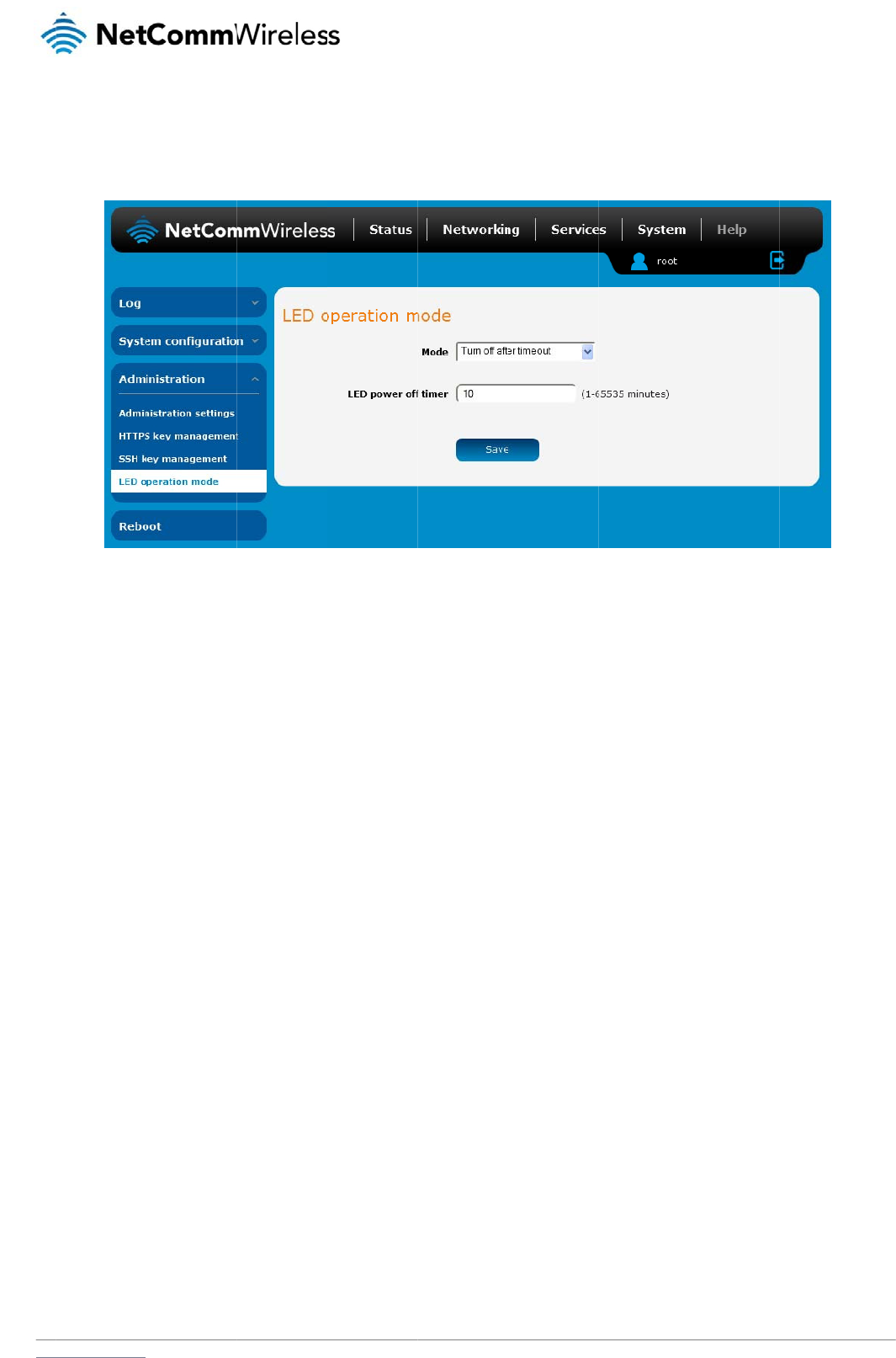
www
L
E
The
on t
h
The
spe
c
indi
c
The
up
a
.netcommwireless.com
E
D operati
7 front LED indicato
r
h
e left and finally sel
e
Mode drop down lis
t
c
ified period, select
T
c
ators. The LED Pow
e
wait period begins f
r
a
nd wait for the confi
g
i
on mode
r
s may be turned off
a
e
ct LED Operation
M
t
sets the operation
m
T
urn off after timeou
t
e
r Off Timer must be
r
om the time the Sav
e
g
ured time before tu
r
a
fter a timeout perio
d
M
ode.
m
ode of the LEDs on
t
. When configured t
o
an integer between
e
button is clicked.
W
r
ning off again.
d
for aesthetic or po
w
Figu
re
the front panel of th
e
o
turn off after timeo
u
1 and 65535.
W
hen the wait period
w
er saving reasons.
T
re
102 - LED Operatio
n
e
router. To set the li
g
u
t, use the LED pow
e
expires, the LEDs w
i
T
o access the LED
O
n
Mod
e
g
hts to operate at all
t
e
r off timer field to s
p
i
ll turn off. If the rout
e
N
e
O
peration Mode pag
e
t
imes, set this to Alw
a
ecify the time in min
u
e
r is rebooted, the LE
etComm Wireless 3G
e
, click the System
m
w
ays on. To set the li
g
u
tes to wait before t
u
E
D power off timer is
Light Industrial M2M
R
enu, then Administr
a
hts to turn off after a
rning off the LED
reset. The router will
R
oute
r
109
a
tion
boot
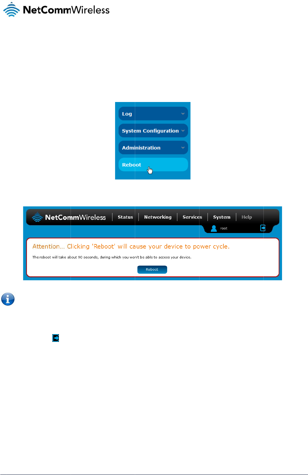
110
Net
C
R
e
The
To r
e
L
o
To l
o
C
omm Wireless 3G Li
g
e
boot
reboot option in the
S
e
boot the router:
1. Click the S
y
2. Click the R
3. The router
d
Note: It can
o
gging ou
t
o
g out of the router,
c
g
ht Industrial M2M Ro
u
S
ystem section perf
o
y
stem menu item fro
m
eboot button from th
e
d
isplays a warning t
h
take up to 2 minute
s
t
c
lick the icon at
u
te
r
o
rms a soft reboot of
m
the top menu bar.
e
menu on the left si
d
h
at you are about to
p
s
for the router to reb
the top right corner
o
t
he router. This can
b
d
e of the screen.
Figu
re
p
erform a reboot. If
y
Figu
re
oot.
o
f the web user inter
f
b
e useful if you have
re
103 - Reboot men
u
y
ou wish to proceed,
re
104 - Reboot confi
r
f
ace.
made configuration
u
optio
n
click the Reboot bu
t
r
matio
n
c
hanges you want t
o
t
on then click OK on
o
implement.
the confirmation wi
n
www.netcommwire
l
n
dow which appears.
l
ess.com

www
A
Ta
b
Ta
b
Ta
b
Ta
b
Ta
b
Ta
b
Ta
b
Ta
b
Ta
b
Ta
b
Ta
b
Ta
b
Ta
b
Ta
b
Ta
b
Ta
b
Ta
b
Ta
b
Ta
b
Ta
b
Ta
b
Ta
b
Ta
b
Ta
b
Ta
b
Ta
b
.netcommwireless.com
A
p
p
b
le 1 - Document
b
le 2 - Device Di
m
b
le 3 - LED Indic
a
b
le 4 - Signal stre
b
le 5 – Interfaces
b
le 6 - PoE powe
r
b
le 7 - Locking p
o
b
le 8 - Average p
o
b
le 9 - Managem
e
b
le 10 - Status pa
b
le 11 - Data con
n
b
le 12 - Connect
o
b
le 13 - Current
M
b
le 14 - IPSec Co
b
le 15 - SMS Set
u
b
le 16 - Inbox/Ou
t
b
le 17 - SMS Dia
g
b
le 18 - List of Va
l
b
le 19 - List of S
M
b
le 22 - SMS dia
g
b
le 23 - System l
o
b
le 24 - Administr
b
le 25 - LAN Man
a
b
le 26 - Web Inte
r
b
le 27 - Telnet Ac
b
le 28 - RJ-45 co
n
p
en
d
Revision History
.
m
ensions ............
.
a
tors ....................
.
ngth LED descri
p
...........................
.
r
classes .............
.
o
wer block pin o
u
o
wer consumpti
o
e
nt account login
ge item details ..
.
n
ection item det
a
o
n demand - Co
n
M
AC / IP / Port filt
e
nfiguration Items
u
p Settings .........
.
t
box icons ..........
.
g
nostic Comman
d
l
id SMS diagnost
M
S diagnostics v
a
g
nostics example
o
g detail levels ...
.
r
ation configurati
o
a
gement Default
r
face Default Set
t
cess ...................
.
n
nector pin outs .
.
d
ix
.
..........................
.
.
..........................
.
.
..........................
.
p
tions .................
.
.
..........................
.
.
..........................
.
u
ts .......................
.
o
n figures ............
.
details ..............
.
.
..........................
.
a
ils ......................
.
n
nect and discon
e
ring rules in effe
..........................
.
.
..........................
.
.
..........................
.
d
Syntax .............
.
ic commands ....
.
a
riables ...............
.
commands .......
.
.
..........................
.
o
n options ..........
.
Settings ............
.
t
ings ...................
.
.
..........................
.
.
..........................
.
A:
T
...........................
...........................
...........................
...........................
...........................
...........................
...........................
...........................
...........................
...........................
...........................
nect timers desc
ct ........................
...........................
...........................
...........................
...........................
...........................
...........................
...........................
...........................
...........................
...........................
...........................
...........................
...........................
T
ab
.
...........................
.
...........................
.
...........................
.
...........................
.
...........................
.
...........................
.
...........................
.
...........................
.
...........................
.
...........................
.
...........................
riptions ...............
.
...........................
.
...........................
.
...........................
.
...........................
.
...........................
.
...........................
.
...........................
.
...........................
.
...........................
.
...........................
.
...........................
.
...........................
.
...........................
.
...........................
les
...........................
...........................
...........................
...........................
...........................
...........................
...........................
...........................
...........................
...........................
...........................
...........................
...........................
...........................
...........................
...........................
...........................
...........................
...........................
...........................
...........................
...........................
...........................
...........................
...........................
...........................
N
e
...........................
.
...........................
.
...........................
.
...........................
.
...........................
.
...........................
.
...........................
.
...........................
.
...........................
.
...........................
.
...........................
.
...........................
.
...........................
.
...........................
.
...........................
.
...........................
.
...........................
.
...........................
.
...........................
.
...........................
.
...........................
.
...........................
.
...........................
.
...........................
.
...........................
.
...........................
.
etComm Wireless 3G
...........................
...........................
...........................
...........................
...........................
...........................
...........................
...........................
...........................
...........................
...........................
...........................
...........................
...........................
...........................
...........................
...........................
...........................
...........................
...........................
...........................
...........................
...........................
...........................
...........................
...........................
Light Industrial M2M
R
...........................
.
...........................
.
...........................
.
...........................
.
...........................
.
...........................
.
...........................
.
...........................
.
...........................
.
...........................
.
...........................
.
...........................
.
...........................
.
...........................
.
...........................
.
...........................
.
...........................
.
...........................
.
...........................
.
...........................
.
...........................
.
...........................
.
...........................
.
...........................
.
...........................
.
...........................
.
R
oute
r
111
.
.... 3
.
.... 8
.
.... 9
.
.. 10
.
.. 11
.
.. 18
.
.. 19
.
.. 19
.
.. 20
.
.. 23
.
.. 25
.
.. 30
.
.. 50
.
.. 54
.
.. 79
.
.. 81
.
.. 86
.
.. 88
.
.. 89
.
.. 91
.
.. 94
.
102
.
115
.
115
.
115
.
120
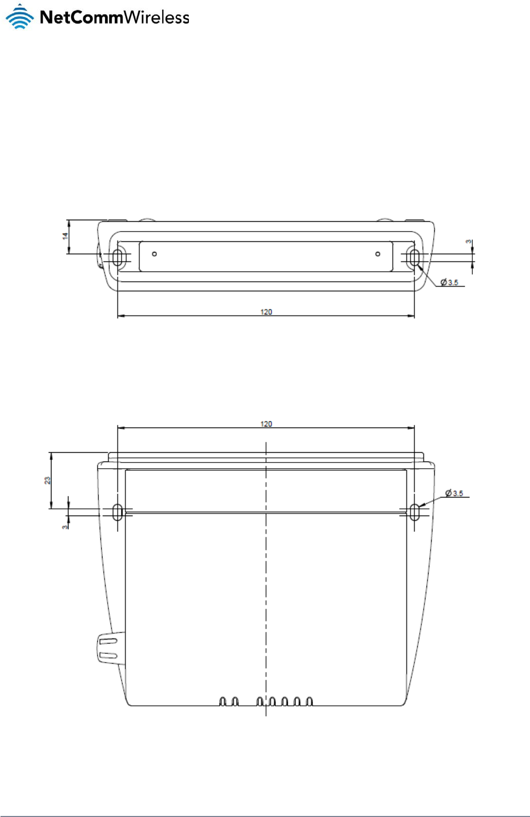
112
NetComm Wireless 3G Light Industrial M2M Route
r
www.netcommwireless.com
Appendix B: Device Mounting
Dimensions
The image below is at 100% scale and may be used as a template for mounting the device. All dimensions shown are in millimetres.
Figure 105 - Device mounting dimensions

www
.netcommwireless.com
N
e
etComm Wireless 3G
Light Industrial M2M
R
R
oute
r
113
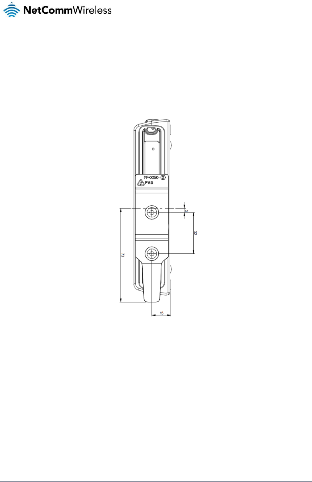
114
NetComm Wireless 3G Light Industrial M2M Route
r
www.netcommwireless.com
Appendix C: Mounting
Bracket
The image below is at 100% scale and may be used as a template for mounting the bracket. All dimensions shown are in millimetres.
Figure 106 - Mounting bracket
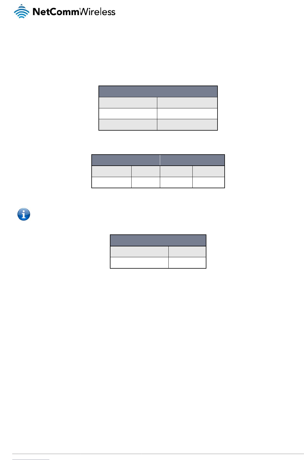
www
A
The
.netcommwireless.com
A
p
p
following tables list t
h
Note: Th
e
to factory
p
en
d
he default settings f
o
e
admin manager ac
c
default settings, whi
d
ix
o
r the 3G Light Indus
t
Static
Subn
e
Defau
ADMI
Username:
Password:
c
ount allows you to
m
ch are privileged on
l
D:
D
t
rial M2M router.
IP Address:
e
t Mask:
l
t Gateway:
Table 26 -
L
N MANAGER ACCO
admi
admi
Table 27
m
anage all settings o
f
y to the root manag
e
3G LIGHT INDUS
T
Username:
Password:
T
D
ef
a
LAN (MANAGEMEN
T
192.168
255.255
192.168
L
AN Management De
f
O
UNT
R
i
n Usern
a
i
n Pass
w
7
- Web Interface Defa
u
f
the router except f
u
e
r account.
TRIAL M2M ROUTE
R
r
a
T
able
28 -
T
elnet Acc
e
a
ul
t
T
)
.1.1
.255.0
.1.1
f
ault Setting
s
R
OOT MANAGER AC
C
a
me: root
w
ord: admi
u
lt Setting
s
u
nctions such as firm
w
R
TELNET ACCESS
r
oo
t
a
dmin
e
s
s
N
e
t
Se
t
C
OUNT
n
w
are upgrade, devi
c
etComm Wireless 3G
t
tin
g
c
e configuration bac
k
Light Industrial M2M
R
g
s
k
up and restore and
r
R
oute
r
115
r
eset

116
NetComm Wireless 3G Light Industrial M2M Route
r
www.netcommwireless.com
Restoring factory default settings
Restoring factory defaults will reset the 3G Light Industrial M2M router to its factory default configuration. You may encounter a situation where you need to restore the factory defaults on your 3G
Light Industrial M2M router such as:
You have lost your username and password and are unable to login to the web configuration page;
You are asked to perform a factory reset by support staff.
There are two methods you can use to restore factory default settings on your 3G Light Industrial M2M router:
Using the web-based user interface
Using the reset button on the interface panel of the router
Using the web-based user interface
To restore your router to its factory default settings, please follow these steps:
1. Open a browser window and navigate to the IP address of the router (default address is http://192.168.1.1). Login to the router using root as the User Name and admin as
the password.
2. Click the System item from the top menu bar, then System configuration on the left menu and then click Settings backup and restore.
3. Under the Restore factory defaults section, click the Restore Defaults button. The router asks you to confirm that you wish to restore factory defaults. Click OK to continue. The
router sets all settings to default. Click OK again to reboot the router.
4. When the Power light returns to a steady red, the reset is complete. The default settings are now restored.
Using the reset button on the interface panel of the router
Use a pen to depress the Reset button on the device for 15-20 seconds. The router will restore the factory default settings and reboot.
When you have reset your 3G Light Industrial M2M router to its default settings you will be able to access the device’s configuration web interface using http://192.168.1.1 with username
admin or root and password admin.
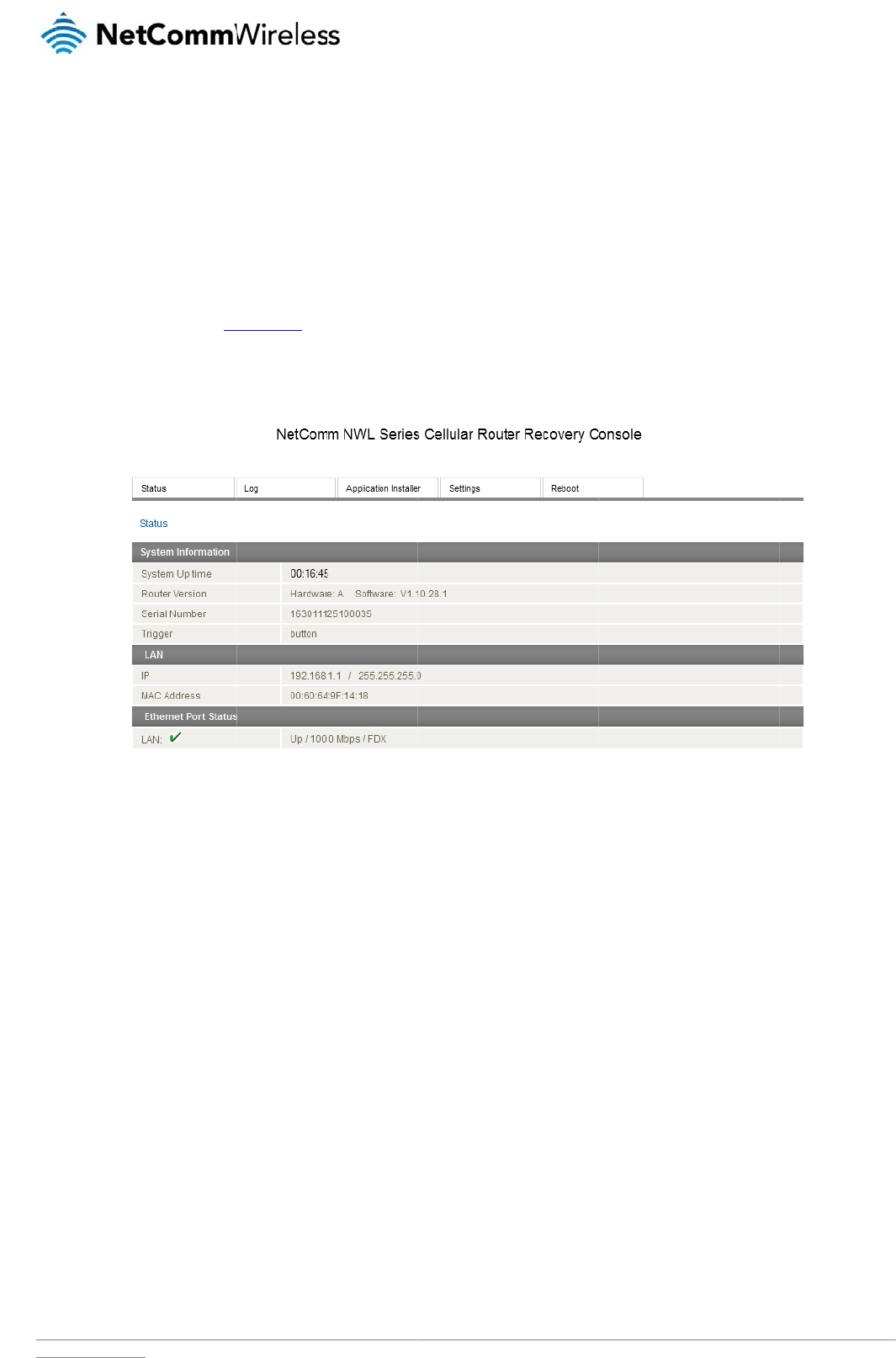
www
R
The
to u
s
Bot
h
may
To s
The
and
and
.netcommwireless.com
ecove
r
3G Light Industrial
M
s
e one in order to re
s
h
systems have Web
be triggered to star
t
tart the router in rec
o
1. Press and
h
release the
2. In your bro
w
The router’
s
recovery console pr
o
install different firm
w
the Reboot tab allo
w
r
y mo
d
M
2M router features t
w
s
tore the other in the
interfaces that can
b
t
in recovery mode if
o
very mode:
h
old the physical re
s
reset button. The ro
w
ser, navigate to htt
p
s
recovery console i
s
o
vides limited functi
o
w
are, allowing you to
w
s you to perform a s
o
d
e
w
o independent ope
event that one syste
m
b
e used to manipulat
e
desired.
s
et button on the inte
r
uter then boots into
r
p
://192.168.1.1. The
s
displayed.
o
nality. Basic status i
n
roll back to a previo
u
o
ft reboot of the rout
e
rating systems, eac
h
m
becomes damage
e
the other inactive s
y
r
face panel of the ro
u
r
ecovery mode.
r
outer’s recovery mo
d
Fig
u
n
formation is availab
u
s firmware in the ev
e
e
r.
h
with its own file sys
t
d or corrupted (suc
h
ystem. The 3G Light
u
ter for 5 to 15 seco
n
de is hardcoded to
u
u
re
107 - Recovery c
o
le, as well as acces
s
e
nt that an upgrade
f
t
ems. These two sys
t
h
as during a firmwar
e
Industrial M2M rout
e
n
ds. When the LEDs
o
u
se this address reg
a
o
nsol
e
s
to the System log f
o
f
ails. The Settings m
e
N
e
ems are referred to
a
e
upgrade failure).
er
starts up by defaul
o
n the front panel ch
a
a
rdless of the IP add
r
r troubleshooting. T
h
e
nu provides the abil
etComm Wireless 3G
a
s 'Main' and 'Recov
l
t in the Main system
ange to amber and
c
r
ess that was config
u
h
e Application Install
e
ity to reset the route
r
Light Industrial M2M
R
ery'. It is always pos
s
mode, however the
r
c
ountdown in a sequ
e
u
red in the main syst
e
e
r can be used to u
p
r
to factory default s
e
R
oute
r
117
s
ible
r
outer
e
nce,
e
m.
p
load
e
ttings
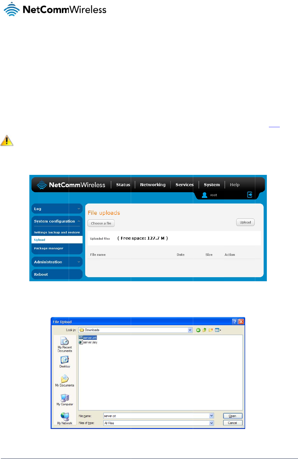
118
Net
C
A
U
c
If yo
To u
C
omm Wireless 3G Li
g
A
p
p
U
pl
o
c
ert
u have your own sel
f
Note: Your k
e
pload your certificat
e
1. Click on th
e
2. Click the C
g
ht Industrial M2M Ro
u
p
en
d
o
a
d
ific
a
f
-signed certificate o
r
e
y and certificate fil
e
e
:
e
System item from t
h
hoose a File button
a
u
te
r
d
ix
d
in
g
a
te
r
one purchased els
e
e
s must be named s
e
h
e top menu ba
r
. Fr
o
a
nd locate your serv
e
E:
H
g
a s
e
where and signed b
rver.key and server.
c
o
m the side menu ba
r
Fi
e
r certificate file and
Figu
re
H
T
T
elf
-
b
y a Certificate Autho
c
rt respectively othe
r
r, select System Co
n
Fi
gure
108 - Upload p
a
click Open.
re
109 - Browse for s
e
T
PS
-
-
sig
n
rity, you can upload
r
wise they will not wo
n
figuration and then
U
a
g
e
e
rver.cr
t
-
n
e
d
it to the 3G Light Ind
rk.
U
pload. The file uplo
a
d
ustrial M2M Router
u
a
d screen is display
e
www.netcommwire
l
u
sing the Upload pa
g
e
d.
l
ess.com
g
e.
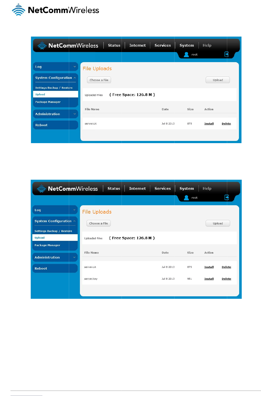
www
.netcommwireless.com
3. Click the U
4. Repeat ste
p
5. Click the I
n
removed fr
o
pload button to begi
n
ps 2 and 3 for the se
n
stall link next to the
s
o
m the list of stored
f
n
uploading it to the
r
rver key file.
s
erver.crt file then cli
c
f
iles.
r
outer. The file appe
a
Figure 11
0
c
k OK on the promp
t
Figure
1
a
rs in the list of files
s
0
- Server certificate
fi
t
that is displayed. T
h
1
1
1
- Installing the se
r
s
tored on the router.
fi
le uploaded
h
e certificate file is in
r
ver.crt fil
e
N
e
s
talled. Repeat this f
etComm Wireless 3G
f
or the key file. When
Light Industrial M2M
R
each file is installed
R
oute
r
119
it is

120
NetComm Wireless 3G Light Industrial M2M Route
r
www.netcommwireless.com
Appendix F: RJ-45 connector
The RJ-45 connector provides an interface for a data connection and for device input power using the pin layout shown below.
Pin: 8 1
Figure 112 -The RJ-45 connector
PIN COLOUR SIGNAL (802.3AF MODE A) SIGNAL (802.3AF MODE B)
1 White/Orange
stripe Rx + Rx + DC +
2 Orange Solid Rx - Rx - DC +
3 White/Green stripe Tx + Tx + DC -
4 Blue solid DC + unused
5 White/Blue stripe DC + unused
6 Green solid Tx - Tx - DC -
7 White/Brown stripe DC - unused
8 Brown solid DC - unused
Table 29 - RJ-45 connector pin outs

www
S
R
You
r
pow
This
This
This
20c
m
E
x
Any
with
req
u
Any
0.2
d
C
This
The
man
The
rele
v
Nor
m
this
d
bod
y
The
qual
Mar
k
This
CE
S
CE
R
CE
E
CE
S
NO
T
This
.netcommwireless.com
S
af
e
F
Exp
o
r
device contains a t
r
er level at which you
device meets the g
o
device is designed
a
device complies wit
h
m
separation from th
e
x
ternal an
t
optional external an
t
any other antenna o
u
ired for high-gain a
n
external antenna ga
i
d
Bi (850MHz) and 2.
7
C
E
A
pp
r
device has been te
s
CE Mark applies to t
ufacturer affixes the
wireless device is a
p
v
ant provisions of th
e
m
s – N 60950 – Prod
u
d
evice has properly
y
number 0682 after
CE Marking is not a
q
ity markings are vol
u
k
ing: The product sh
a
product has also pa
S
AR- EN62311/EN50
R
F – EN301511, EN3
E
MC – EN301489-1/-
S
afety – EN60950
T
E: It is highly recom
m
is a regulatory requi
e
ty
a
o
sure
r
ansmitter and a rec
e
r device transmits.
o
vernment’s require
m
a
nd manufactured n
o
h FCC radiation exp
o
e
body. Failure to ob
t
enna
t
enna used for this tr
a
r transmitter. Please
n
tennas.
i
n must meet RF exp
o
7
dBi (1900MHz).
r
oval
s
ted to and conform
s
he products regulat
e
marking in order to
b
p
proved to be used i
n
e
Radio and Telecom
uct Safety, EN 301 4
8
demonstrated that t
h
the CE mark.
q
uality mark. Forem
o
u
ntary.
a
ll bear the CE mark
a
ssed the following c
e
385
01908-1/-2,
7
/
-24, EN55022/EN5
m
ended that the dev
rement and applies
t
a
nd
e
iver. When it is on, i
t
m
ents for exposure t
o
o
t to exceed the emi
s
o
sure limits set forth
f
serve these instructi
o
a
nsmitter must be in
s
consult the health a
n
o
sure and maximum
s
to the regulatory re
q
e
d by the central Eur
o
b
e allowed to sell the
n
the member states
munications Termin
a
8
9 EMC, EN301511
G
h
e requirements of th
o
st, it refers to the sa
f
, the notified body n
u
e
rtification standard
s
5024
ice must be kept at l
e
t
o all 3G capable de
v
pr
o
receives and trans
m
radio waves.
s
sion limits for expos
f
or an uncontrolled e
o
ns could result in y
o
s
talled to provide a s
e
n
d safety guide of th
e
radiated output po
w
q
uirements of the Eu
r
o
pean health, safety
ir product in the Eur
o
of the EU. NetCom
m
a
l Equipment Directi
v
G
SM RF, EN301908
e directive have bee
f
ety rather than to th
e
u
mber(s) as depicte
d
s
–
e
ast 20cm away fro
m
v
ices meeting stand
a
o
d
u
m
its RF energy. Whe
n
s
ure to radio frequen
c
nvironment. To ensu
o
ur RF exposure exc
e
eparation distance
o
e
chosen antenna fo
r
w
er limits of the appli
c
r
opean Union and at
t
and environmental
p
o
pean market.
m
Wireless declares t
v
e 1999/5/EC (R&TT
E
UMTS RF, EN 62311
n met and has issue
d
e
quality of the prod
u
d
to the right. CE068
2
m
the human body.
a
rd regulatory compl
u
ct
c
n
you communicate
w
c
y (RF) energy set b
y
re compliance with
R
e
eding the relevant
g
o
f at least 20 cm from
r
specific body sepa
r
c
able rule section. T
h
t
ained CE Marking.
T
p
rotection legislation.
hat the wireless devi
c
E
Directive). Complia
n
SAR Technical req
u
d
a favourable certifi
u
ct. Secondly, CE M
a
2
.
iance such as the c
o
N
e
c
ar
e
w
ith your device, the
s
y
the Federal Comm
u
R
F exposure guidelin
e
g
uideline limits.
all pe
r
sons and mu
s
r
ation guidelines as
a
h
e maximum antenn
a
he CE Mark is a con
f
The CE Mark is obli
g
c
e is in compliance
w
n
ce with this directiv
e
irement for radio eq
u
c
ate of expert opinio
rking is mandatory f
o
mpliance standards
etComm Wireless 3G
e
system handling yo
u
u
nications Commissi
o
es the device must
b
s
t not be co-located
o
a
greater distance of
a
gain for this device
formity marking con
s
g
atory for products i
t
w
ith the essential re
q
e
implies conformity
u
ipment. A notified b
o
n. As such the devi
c
o
r the product it app
listed above.
Light Industrial M2M
R
u
r connection control
s
o
n of the U.S. Gover
n
b
e used with a minim
o
r operated in conju
n
separation may be
as reported to the F
C
s
isting of the letters “
C
t
applies to: the
q
uirements and other
to the following Euro
o
dy has determined
e will bear the notifi
e
l
ies to whereas most
R
oute
r
121
s
the
n
ment.
um of
n
ction
C
C is:
C
E.”
pean
that
e
d

122
NetComm Wireless 3G Light Industrial M2M Route
r
www.netcommwireless.com
FCC Statement
FCC compliance
Federal Communications Commission Notice (United States): Before a wireless device model is available for sale to the public, it must be tested and certified to the FCC that it does not exceed
the limit established by the government-adopted requirement for safe exposure.
FCC regulations
§ 15.19 (a)(3)
This device complies with part 15 of the FCC Rules. Operation is subject to the following two conditions: (1) This device may not cause harmful interference, and (2) this device must accept any
interference received, including interference that may cause undesired operation.
§ 15.21
Changes or modifications not expressly approved by the party responsible for compliance could void the user‘s authority to operate the equipment.
****************************************************************************************************************************
§ 15.105 (b)
This equipment has been tested and found to comply with the limits for a Class B digital device, pursuant to part 15 of the FCC Rules. These limits are designed to provide reasonable protection
against harmful interference in a residential installation. This equipment generates, uses and can radiate radio frequency energy and, if not installed and used in accordance with the instructions,
may cause harmful interference to radio communications. However, there is no guarantee that interference will not occur in a particular installation. If this equipment does cause harmful
interference to radio or television reception, which can be determined by turning the equipment off and on, the user is encouraged to try to correct the interference by one or more of the
following measures:
—Reorient or relocate the receiving antenna.
—Increase the separation between the equipment and receiver.
—Connect the equipment into an outlet on a circuit different from that to which the receiver is connected.
—Consult the dealer or an experienced radio/TV technician for help.
RF Exposure Information (MPE)
This equipment complies with radio frequency (RF) exposure limits adopted by the Federal Communications Commission for an uncontrolled environment. This equipment should be installed
and operated with minimum distance 20 cm between the radiator & your body.

www
I
C
RS
S
This
(1) t
h
(2) t
h
Le
p
(1) l'
(2) l'
****
*
ICE
S
CA
N
****
*
RSS
This
ant
e
Ant
e
Ant
e
**
*
IC
Th
eq
.netcommwireless.com
C
Reg
u
S
-Gen 7.1.3
device complies wit
h
h
is device may not c
h
is device must acc
e
p
résent appareil est
c
appareil ne doit pas
utilisateur de l'appa
r
***********************
*
S
-003
N
ICES-3(B)/ NMB-3(
B
***********************
*
-Gen 7.1.2
radio transmitter ha
s
nna type indicated.
A
e
nna types: Dipole
e
nna gain: 850MHz:
0
*
*************
*
RF Expos
is equipmen
uipment sh
o
u
lation
s
h Industry Canada li
c
ause interference, a
n
e
pt any interference,
c
onforme aux CNR d
'
produire de brouilla
g
r
eil doit accepter tou
t
*
**********************
*
B
)
*
**********************
*
s
been approved by
A
ntenna types not in
c
0
.2dBi; 1900MHz: 2.
7
*
*************
*
ure State
m
t complies
w
o
uld be instal
s
:
c
ense-exempt RSS
s
n
d
including interferen
c
'
Industrie Canada a
p
g
e, et
t
brouillage radioéle
c
*
***********************
*
*
***********************
*
Industry Canada to
o
c
luded in this list, ha
v
7
dBi
*
*************
*
m
ent (MPE)
w
ith IC RSS-
1
led and ope
r
tandard(s). Operatio
c
e that may cause u
n
p
plicables aux appar
e
c
trique subi, même si
*
**********************
*
*
**********************
*
o
perate with the ante
v
ing a gain greater t
h
*
*************
*
1
02 RF exp
o
r
ated with m
i
o
n is subject to the fo
n
desired operation o
f
eils radio exempts d
e
i
le brouillage est su
s
*
***********************
*
***********************
nna types listed bel
o
h
an the maximum g
a
*************
*
o
sure limits
s
inimum dist
a
llowing two conditio
n
f
the device.
e
licence. L'exploitat
s
ceptible d'en comp
r
**
**
o
w with the maximu
m
a
in indicated for that
t
*
*************
*
s
et forth for
a
a
nce 20 cm
b
N
e
n
s:
i
on est autorisée aux
r
omettre le fonctionn
e
permissible gain an
t
ype, are strictly pro
h
*
*************
*
n uncontroll
e
b
etween the
etComm Wireless 3G
x
deux conditions sui
v
e
ment."
n
d required antenna i
h
ibited for use with t
h
*
*************
*
e
d environm
radiator & y
o
Light Industrial M2M
R
v
antes:
mpedance for each
h
is device.
*
**********
ent. This
o
ur body.
R
oute
r
123

124
NetComm Wireless 3G Light Industrial M2M Route
r
www.netcommwireless.com
Electrical safety
Accessories
Only use approved accessories.
Do not connect with incompatible products or accessories.
Connection to a car
Seek professional advice when connecting a device interface to the vehicle electrical system.
Distraction
Operating machinery
Full attention must be given to operating the machinery in order to reduce the risk of an accident.
Product handling
You alone are responsible for how you use your device and any consequences of its use.
You must always switch off your device wherever the use of a mobile phone is prohibited. Do not use the device without the clip-on covers attached, and do not remove or change the covers
while using the device. Use of your device is subject to safety measures designed to protect users and their environment.
Always treat your device and its accessories with care and keep it in a clean and dust-free place.
Do not expose your device or its accessories to open flames or lit tobacco products.
Do not expose your device or its accessories to liquid, moisture or high humidity.
Do not drop, throw or try to bend your device or its accessories.
Do not use harsh chemicals, cleaning solvents, or aerosols to clean the device or its accessories.
Do not paint your device or its accessories.
Do not attempt to disassemble your device or its accessories, only authorised personnel must do so.
Do not use or install this product in extremely hot or cold areas. Ensure that the device is installed in an area where the temperature is within the supported operating temperature range (-20°C to
65°C)
Do not use your device in an enclosed environment or where heat dissipation is poor. Prolonged use in such space may cause excessive heat and raise ambient temperature, which will lead to
automatic shutdown of your device or the disconnection of the mobile network connection for your safety. To use your device normally again after such shutdown, cool it in a well-ventilated place
before turning it on.
Please check local regulations for disposal of electronic products.
Do not operate the device where ventilation is restricted
Installation and configuration should be performed by trained personnel only.
Do not use or install this product near water to avoid fire or shock hazard. Avoid exposing the equipment to rain or damp areas.
Arrange power and Ethernet cables in a manner such that they are not likely to be stepped on or have items placed on them.
Ensure that the voltage and rated current of the power source match the requirements of the device. Do not connect the device to an inappropriate power source.
Small children
Do not leave your device and its accessories within the reach of small children or allow them to play with it.
They could hurt themselves or others, or could accidentally damage the device.
Your device contains small parts with sharp edges that may cause an injury or which could become detached and create a choking hazard.

www
E
m
This
em
e
D
e
You
r
F
a
Do
n
Onl
y
If yo
.netcommwireless.com
m
ergency
device, like any wir
e
rgency communicati
e
vice hea
t
r
device may becom
e
a
ulty a
n
n
ot attempt to disass
e
y
qualified personnel
ur device or its acce
situation
s
e
less device, operat
e
ons.
t
ing
e
warm during norm
a
nd da
m
e
mble the device or
must service or rep
a
ssories have been s
u
s
e
s using radio signal
s
a
l use.
m
aged
its accessories.
a
ir the device or its a
c
u
bmerged in water
p
s
, which cannot guar
a
produ
c
c
cessories.
unctured or subject
e
antee connection in
a
c
ts
e
d to a severe fall, d
o
a
ll conditions. There
f
o
not use until they h
a
N
e
f
ore, you must never
a
ve been checked a
t
etComm Wireless 3G
rely solely on any wi
t
an authorised servi
c
Light Industrial M2M
R
r
eless device for
c
e centre.
R
oute
r
125

126
NetComm Wireless 3G Light Industrial M2M Route
r
www.netcommwireless.com
Interference
Care must be taken when using the device in close proximity to personal medical devices, such as pacemakers and hearing aids.
Pacemakers
Pacemaker manufacturers recommend that a minimum separation of 15cm be maintained between a device and a pacemaker to avoid potential interference with the pacemaker.
Hearing aids
People with hearing aids or other cochlear implants may experience interfering noises when using wireless devices or when one is nearby.
The level of interference will depend on the type of hearing device and the distance from the interference source, increasing the separation between them may reduce the interference. You may
also consult your hearing aid manufacturer to discuss alternatives.
Medical devices
Please consult your doctor and the device manufacturer to determine if operation of your device may interfere with the operation of your medical device.
Hospitals
Switch off your wireless device when requested to do so in hospitals, clinics or health care facilities. These requests are designed to prevent possible interference with sensitive medical
equipment.
Interference in cars
Please note that because of possible interference to electronic equipment, some vehicle manufacturers forbid the use of devices in their vehicles unless an external antenna is included in the
installation.
Explosive environments
Petrol stations and explosive atmospheres
In locations with potentially explosive atmospheres, obey all posted signs to turn off wireless devices such as your device or other radio equipment.
Areas with potentially explosive atmospheres include fuelling areas, below decks on boats, fuel or chemical transfer or storage facilities, areas where the air contains chemicals or particles, such
as grain, dust, or metal powders.
Blasting caps and areas
Turn off your device or wireless device when in a blasting area or in areas posted turn off “two-way radios” or “electronic devices” to avoid interfering with blasting operations.