Netgear orporated 05100002 54 Mbps Wireless Router User Manual FullManual
Netgear Incorporated 54 Mbps Wireless Router FullManual
Contents
- 1. User Manual 1
- 2. User Manual 2
- 3. User Manual 3
User Manual 3

Network, Routing, Firewall, and Basics B-1
July 2004 202-10036-01
Appendix B
Network, Routing, Firewall, and Basics
This chapter provides an overview of IP networks, routing, and networking.
Related Publications
As you read this document, you may be directed to various RFC documents for further
information. An RFC is a Request For Comment (RFC) published by the Internet Engineering
Task Force (IETF), an open organization that defines the architecture and operation of the Internet.
The RFC documents outline and define the standard protocols and procedures for the Internet. The
documents are listed on the World Wide Web at www.ietf.org and are mirrored and indexed at
many other sites worldwide.
Basic Router Concepts
Large amounts of bandwidth can be provided easily and relatively inexpensively in a local area
network (LAN). However, providing high bandwidth between a local network and the Internet can
be very expensive. Because of this expense, Internet access is usually provided by a slower-speed
wide-area network (WAN) link such as a cable or DSL modem. In order to make the best use of the
slower WAN link, a mechanism must be in place for selecting and transmitting only the data traffic
meant for the Internet. The function of selecting and forwarding this data is performed by a router.
What is a Router?
A router is a device that forwards traffic between networks based on network layer information in
the data and on routing tables maintained by the router. In these routing tables, a router builds up a
logical picture of the overall network by gathering and exchanging information with other routers
in the network. Using this information, the router chooses the best path for forwarding network
traffic.
Routers vary in performance and scale, number of routing protocols supported, and types of
physical WAN connection they support. The 54 Mbps Wireless Router WGR614 v6 is a small
office router that routes the IP protocol over a single-user broadband connection.

Reference Manual for the 54 Mbps Wireless Router WGR614 v6
B-2 Network, Routing, Firewall, and Basics
July 2004 202-10036-01
Routing Information Protocol
One of the protocols used by a router to build and maintain a picture of the network is the Routing
Information Protocol (RIP). Using RIP, routers periodically update one another and check for
changes to add to the routing table.
The WGR614 v6 router supports both the older RIP-1 and the newer RIP-2 protocols. Among
other improvements, RIP-2 supports subnet and multicast protocols. RIP is not required for most
home applications.
IP Addresses and the Internet
Because TCP/IP networks are interconnected across the world, every machine on the Internet must
have a unique address to make sure that transmitted data reaches the correct destination. Blocks of
addresses are assigned to organizations by the Internet Assigned Numbers Authority (IANA).
Individual users and small organizations may obtain their addresses either from the IANA or from
an Internet service provider (ISP). You can contact IANA at www.iana.org.
The Internet Protocol (IP) uses a 32-bit address structure. The address is usually written in dot
notation (also called dotted-decimal notation), in which each group of eight bits is written in
decimal form, separated by decimal points.
For example, the following binary address:
11000011 00100010 00001100 00000111
is normally written as:
195.34.12.7
The latter version is easier to remember and easier to enter into your computer.
In addition, the 32 bits of the address are subdivided into two parts. The first part of the address
identifies the network, and the second part identifies the host node or station on the network. The
dividing point may vary depending on the address range and the application.
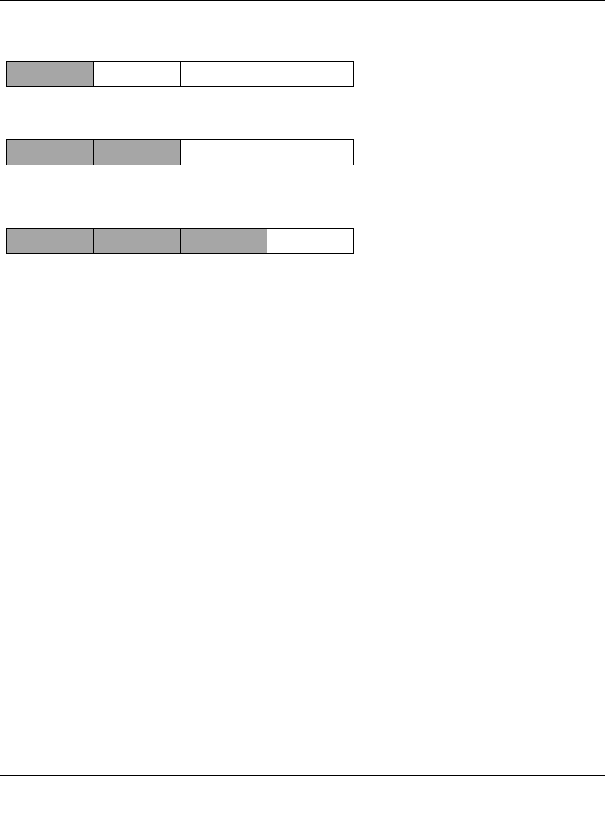
There are five standard classes of IP addresses. These address classes have different ways of
determining the network and host sections of the address, allowing for different numbers of hosts
on a network. Each address type begins with a unique bit pattern, which is used by the TCP/IP
software to identify the address class. After the address class has been determined, the software
can correctly identify the host section of the address. The follow figure shows the three main
address classes, including network and host sections of the address for each address type.
Reference Manual for the 54 Mbps Wireless Router WGR614 v6
Network, Routing, Firewall, and Basics B-3
July 2004 202-10036-01
Figure B-1: Three Main Address Classes
The five address classes are:
• Class A
Class A addresses can have up to 16,777,214 hosts on a single network. They use an eight-bit
network number and a 24-bit node number. Class A addresses are in this range:
1.x.x.x to 126.x.x.x.
• Class B
Class B addresses can have up to 65,354 hosts on a network. A Class B address uses a 16-bit
network number and a 16-bit node number. Class B addresses are in this range:
128.1.x.x to 191.254.x.x.
• Class C
Class C addresses can have 254 hosts on a network. Class C addresses use 24 bits for the
network address and eight bits for the node. They are in this range:
192.0.1.x to 223.255.254.x.
• Class D
Class D addresses are used for multicasts (messages sent to many hosts). Class D addresses are
in this range:
224.0.0.0 to 239.255.255.255.
• Class E
Class E addresses are for experimental use.
7261
C
lass A
N
etwork Node
C
lass B
C
lass C
Network Node
Network Node

Reference Manual for the 54 Mbps Wireless Router WGR614 v6
B-4 Network, Routing, Firewall, and Basics
July 2004 202-10036-01
This addressing structure allows IP addresses to uniquely identify each physical network and each
node on each physical network.
For each unique value of the network portion of the address, the base address of the range (host
address of all zeros) is known as the network address and is not usually assigned to a host. Also,
the top address of the range (host address of all ones) is not assigned, but is used as the broadcast
address for simultaneously sending a packet to all hosts with the same network address.
Netmask
In each of the address classes previously described, the size of the two parts (network address and
host address) is implied by the class. This partitioning scheme can also be expressed by a netmask
associated with the IP address. A netmask is a 32-bit quantity that, when logically combined (using
an AND operator) with an IP address, yields the network address. For instance, the netmasks for
Class A, B, and C addresses are 255.0.0.0, 255.255.0.0, and 255.255.255.0, respectively.
For example, the address 192.168.170.237 is a Class C IP address whose network portion is the
upper 24 bits. When combined (using an AND operator) with the Class C netmask, as shown here,
only the network portion of the address remains:
11000000 10101000 10101010 11101101 (192.168.170.237)
combined with:
11111111 11111111 11111111 00000000 (255.255.255.0)
Equals:
11000000 10101000 10101010 00000000 (192.168.170.0)
As a shorter alternative to dotted-decimal notation, the netmask may also be expressed in terms of
the number of ones from the left. This number is appended to the IP address, following a backward
slash (/), as “/n.” In the example, the address could be written as 192.168.170.237/24, indicating
that the netmask is 24 ones followed by 8 zeros.
Subnet Addressing
By looking at the addressing structures, you can see that even with a Class C address, there are a
large number of hosts per network. Such a structure is an inefficient use of addresses if each end of
a routed link requires a different network number. It is unlikely that the smaller office LANs would
have that many devices. You can resolve this problem by using a technique known as subnet
addressing.
Reference Manual for the 54 Mbps Wireless Router WGR614 v6
Network, Routing, Firewall, and Basics B-5
July 2004 202-10036-01
Subnet addressing allows us to split one IP network address into smaller multiple physical
networks known as subnetworks. Some of the node numbers are used as a subnet number instead.
A Class B address gives us 16 bits of node numbers translating to 64,000 nodes. Most
organizations do not use 64,000 nodes, so there are free bits that can be reassigned. Subnet
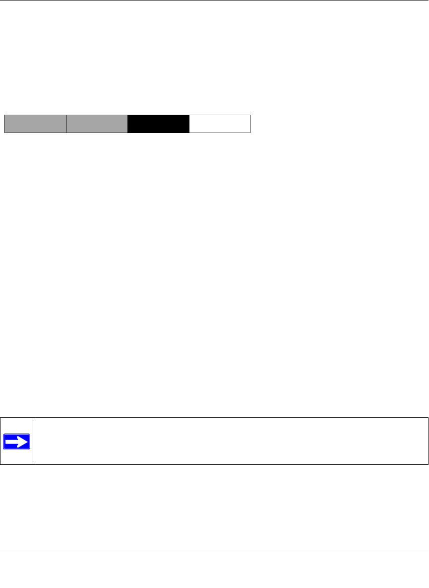
addressing makes use of those bits that are free, as shown below.
Figure B-2: Example of Subnetting a Class B Address
A Class B address can be effectively translated into multiple Class C addresses. For example, the
IP address of 172.16.0.0 is assigned, but node addresses are limited to 255 maximum, allowing
eight extra bits to use as a subnet address. The IP address of 172.16.97.235 would be interpreted as
IP network address 172.16, subnet number 97, and node number 235. In addition to extending
the number of addresses available, subnet addressing provides other benefits. Subnet addressing
allows a network manager to construct an address scheme for the network by using different
subnets for other geographical locations in the network or for other departments in the
organization.
Although the preceding example uses the entire third octet for a subnet address, note that you are
not restricted to octet boundaries in subnetting. To create more network numbers, you need only
shift some bits from the host address to the network address. For instance, to partition a Class C
network number (192.68.135.0) into two, you shift one bit from the host address to the network
address. The new netmask (or subnet mask) is 255.255.255.128. The first subnet has network
number 192.68.135.0 with hosts 192.68.135.1 to 129.68.135.126, and the second subnet has
network number 192.68.135.128 with hosts 192.68.135.129 to 192.68.135.254.
Note: The number 192.68.135.127 is not assigned because it is the broadcast address
of the first subnet. The number 192.68.135.128 is not assigned because it is the network
address of the second subnet.
7262
C
lass B
Network Subnet Node

Reference Manual for the 54 Mbps Wireless Router WGR614 v6
B-6 Network, Routing, Firewall, and Basics
July 2004 202-10036-01
The following table lists the additional subnet mask bits in dotted-decimal notation. To use the
table, write down the original class netmask and replace the 0 value octets with the dotted-decimal
value of the additional subnet bits. For example, to partition your Class C network with subnet
mask 255.255.255.0 into 16 subnets (4 bits), the new subnet mask becomes 255.255.255.240.
The following table displays several common netmask values in both the dotted-decimal and the
masklength formats.
Configure all hosts on a LAN segment to use the same netmask for the following reasons:
Table 8-1. Netmask Notation Translation Table for One Octet
Number of Bits Dotted-Decimal Value
1 128
2 192
3 224
4 240
5 248
6 252
7 254
8 255
Table 8-2. Netmask Formats
Dotted-Decimal Masklength
255.0.0.0 /8
255.255.0.0 /16
255.255.255.0 /24
255.255.255.128 /25
255.255.255.192 /26
255.255.255.224 /27
255.255.255.240 /28
255.255.255.248 /29
255.255.255.252 /30
255.255.255.254 /31
255.255.255.255 /32

Reference Manual for the 54 Mbps Wireless Router WGR614 v6
Network, Routing, Firewall, and Basics B-7
July 2004 202-10036-01
• So that hosts recognize local IP broadcast packets
When a device broadcasts to its segment neighbors, it uses a destination address of the local
network address with all ones for the host address. In order for this scheme to work, all devices
on the segment must agree on which bits comprise the host address.
• So that a local router or bridge recognizes which addresses are local and which are remote
Private IP Addresses
If your local network is isolated from the Internet (for example, when using NAT), you can assign
any IP addresses to the hosts without problems. However, the IANA has reserved the following
three blocks of IP addresses specifically for private networks:
10.0.0.0 - 10.255.255.255
172.16.0.0 - 172.31.255.255
192.168.0.0 - 192.168.255.255
Choose your private network number from this range. The DHCP server of the WGR614 v6 router
is preconfigured to automatically assign private addresses.
Regardless of your particular situation, do not create an arbitrary IP address; always follow the
guidelines explained here. For more information about address assignment, refer to RFC 1597,
Address Allocation for Private Internets, and RFC 1466, Guidelines for Management of IP
Address Space. The Internet Engineering Task Force (IETF) publishes RFCs on its Web site at
www.ietf.org.
Single IP Address Operation Using NAT
In the past, if multiple computers on a LAN needed to access the Internet simultaneously, you had
to obtain a range of IP addresses from the ISP. This type of Internet account is more costly than a
single-address account typically used by a single user with a modem, rather than a router. The
WGR614 v6 router employs an address-sharing method called Network Address Translation
(NAT). This method allows several networked computers to share an Internet account using only a
single IP address, which may be statically or dynamically assigned by your ISP.
The router accomplishes this address sharing by translating the internal LAN IP addresses to a
single address that is globally unique on the Internet. The internal LAN IP addresses can be either
private addresses or registered addresses. For more information about IP address translation, refer
to RFC 1631, The IP Network Address Translator (NAT).
Reference Manual for the 54 Mbps Wireless Router WGR614 v6
B-8 Network, Routing, Firewall, and Basics
July 2004 202-10036-01
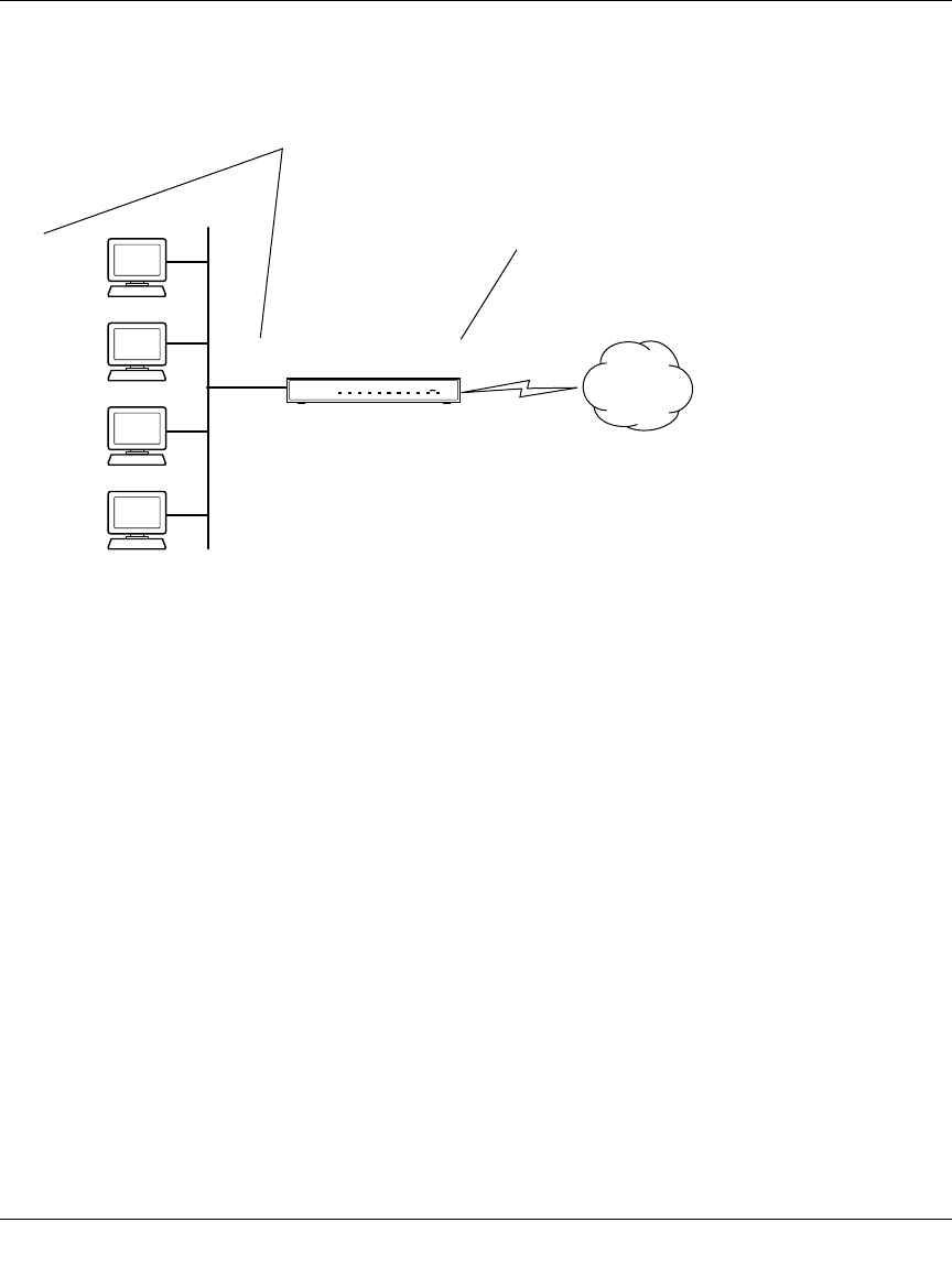
The following figure illustrates a single IP address operation.
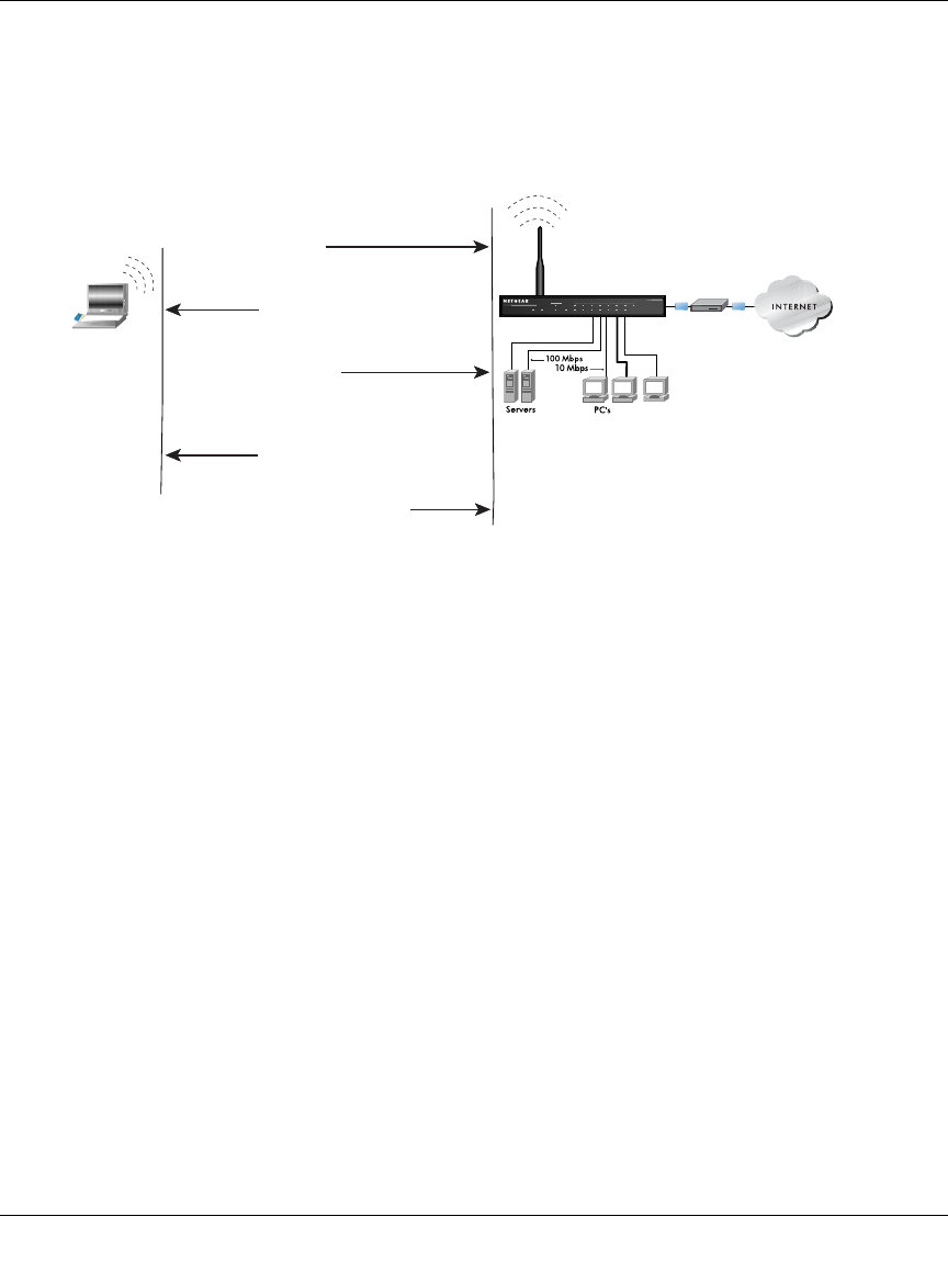
Figure B-3: Single IP Address Operation Using NAT
This scheme offers the additional benefit of firewall-like protection because the internal LAN
addresses are not available to the Internet through the translated connection. All incoming
inquiries are filtered out by the router. This filtering can prevent intruders from probing your
system. However, using port forwarding, you can allow one computer (for example, a Web server)
on your local network to be accessible to outside users.
MAC Addresses and Address Resolution Protocol
An IP address alone cannot be used to deliver data from one LAN device to another. To send data
between LAN devices, you must convert the IP address of the destination device to its media
access control (MAC) address. Each device on an Ethernet network has a unique MAC address,
which is a 48-bit number assigned to each device by the manufacturer. The technique that
associates the IP address with a MAC address is known as address resolution. Internet Protocol
uses the Address Resolution Protocol (ARP) to resolve MAC addresses.
7786EA
1
92.168.0.2
1
92.168.0.3
1
92.168.0.4
1
92.168.0.5
192.168.0.1 172.21.15.105
Private IP addresses
assigned by user
Internet
IP addresses
assigned by ISP

Reference Manual for the 54 Mbps Wireless Router WGR614 v6
Network, Routing, Firewall, and Basics B-9
July 2004 202-10036-01
If a device sends data to another station on the network and the destination MAC address is not yet
recorded, ARP is used. An ARP request is broadcast onto the network. All stations on the network
receive and read the request. The destination IP address for the chosen station is included as part of
the message so that only the station with this IP address responds to the ARP request. All other
stations discard the request.
Related Documents
The station with the correct IP address responds with its own MAC address directly to the sending
device. The receiving station provides the transmitting station with the required destination MAC
address. The IP address data and MAC address data for each station are held in an ARP table. The
next time data is sent, the address can be obtained from the address information in the table.
For more information about address assignment, refer to the IETF documents RFC 1597, Address
Allocation for Private Internets, and RFC 1466, Guidelines for Management of IP Address Space.
For more information about IP address translation, refer to RFC 1631, The IP Network Address
Translator (NAT).
Domain Name Server
Many of the resources on the Internet can be addressed by simple descriptive names such as
www.NETGEAR.com. This addressing is very helpful at the application level, but the descriptive
name must be translated to an IP address in order for a user to actually contact the resource. Just as
a telephone directory maps names to phone numbers, or as an ARP table maps IP addresses to
MAC addresses, a domain name system (DNS) server maps descriptive names of network
resources to IP addresses.
When a computer accesses a resource by its descriptive name, it first contacts a DNS server to
obtain the IP address of the resource. The computer sends the desired message using the IP
address. Many large organizations, such as ISPs, maintain their own DNS servers and allow their
customers to use the servers to look up addresses.

Reference Manual for the 54 Mbps Wireless Router WGR614 v6
B-10 Network, Routing, Firewall, and Basics
July 2004 202-10036-01
IP Configuration by DHCP
When an IP-based local area network is installed, each computer must be configured with an
IP address. If the computers need to access the Internet, they should also be configured with a
gateway address and one or more DNS server addresses. As an alternative to manual
configuration, there is a method by which each computer on the network can automatically obtain
this configuration information. A device on the network may act as a Dynamic Host Configuration
Protocol (DHCP) server. The DHCP server stores a list or pool of IP addresses, along with other
information (such as gateway and DNS addresses) that it may assign to the other devices on the
network. The WGR614 v6 router has the capacity to act as a DHCP server.
The WGR614 v6 router also functions as a DHCP client when connecting to the ISP. The firewall
can automatically obtain an IP address, subnet mask, DNS server addresses, and a gateway address
if the ISP provides this information by DHCP.
Internet Security and Firewalls
When your LAN connects to the Internet through a router, an opportunity is created for outsiders
to access or disrupt your network. A NAT router provides some protection because by the very
nature of the process, the network behind the router is shielded from access by outsiders on the
Internet. However, there are methods by which a determined hacker can possibly obtain
information about your network or at the least can disrupt your Internet access. A greater degree of
protection is provided by a firewall router.
What is a Firewall?
A firewall is a device that protects one network from another, while allowing communication
between the two. A firewall incorporates the functions of the NAT router, while adding features for
dealing with a hacker intrusion or attack. Several known types of intrusion or attack can be
recognized when they occur. When an incident is detected, the firewall can log details of the
attempt, and can optionally send E-mail to an administrator notifying them of the incident. Using
information from the log, the administrator can take action with the ISP of the hacker. In some
types of intrusions, the firewall can fend off the hacker by discarding all further packets from the
hacker’s IP address for a period of time.

Reference Manual for the 54 Mbps Wireless Router WGR614 v6
Network, Routing, Firewall, and Basics B-11
July 2004 202-10036-01
Stateful Packet Inspection
Unlike simple Internet sharing routers, a firewall uses a process called stateful packet inspection to
ensure secure firewall filtering to protect your network from attacks and intrusions. Since
user-level applications such as FTP and Web browsers can create complex patterns of network
traffic, it is necessary for the firewall to analyze groups of network connection states. Using
Stateful Packet Inspection, an incoming packet is intercepted at the network layer and then
analyzed for state-related information associated with all network connections. A central cache
within the firewall keeps track of the state information associated with all network connections.
All traffic passing through the firewall is analyzed against the state of these connections in order to
determine whether or not it will be allowed to pass through or rejected.
Denial of Service Attack
A hacker may be able to prevent your network from operating or communicating by launching a
Denial of Service (DoS) attack. The method used for such an attack can be as simple as merely
flooding your site with more requests than it can handle. A more sophisticated attack may attempt
to exploit some weakness in the operating system used by your router or gateway. Some operating
systems can be disrupted by simply sending a packet with incorrect length information.
Ethernet Cabling
Although Ethernet networks originally used thick or thin coaxial cable, most installations currently
use unshielded twisted pair (UTP) cabling. The UTP cable contains eight conductors, arranged in
four twisted pairs, and terminated with an RJ45 type connector. A normal straight-through UTP
Ethernet cable follows the EIA568B standard wiring as described below in Table B-1.
Reference Manual for the 54 Mbps Wireless Router WGR614 v6
B-12 Network, Routing, Firewall, and Basics
July 2004 202-10036-01
Category 5 Cable Quality
Category 5 distributed cable that meets ANSI/EIA/TIA-568-A building wiring standards can be a
maximum of 328 feet (ft.) or 100 meters (m) in length, divided as follows:
20 ft. (6 m) between the hub and the patch panel (if used)
295 ft. (90 m) from the wiring closet to the wall outlet
10 ft. (3 m) from the wall outlet to the desktop device
The patch panel and other connecting hardware must meet the requirements for 100 Mbps
operation (Category 5). Only 0.5 inch (1.5 cm) of untwist in the wire pair is allowed at any
termination point.
A twisted pair Ethernet network operating at 10 Mbits/second (10BASE-T) will often tolerate low
quality cables, but at 100 Mbits/second (10BASE-Tx) the cable must be rated as Category 5, or
Cat 5, by the Electronic Industry Association (EIA). This rating will be printed on the cable jacket.
A Category 5 cable will meet specified requirements regarding loss and crosstalk. In addition,
there are restrictions on maximum cable length for both 10 and 100 Mbits/second networks.
Table B-1. UTP Ethernet cable wiring, straight-through
Pin Wire color Signal
1 Orange/White Transmit (Tx) +
2 Orange Transmit (Tx) -
3 Green/White Receive (Rx) +
4Blue
5 Blue/White
6 Green Receive (Rx) -
7 Brown/White
8Brown
Reference Manual for the 54 Mbps Wireless Router WGR614 v6
Network, Routing, Firewall, and Basics B-13
July 2004 202-10036-01
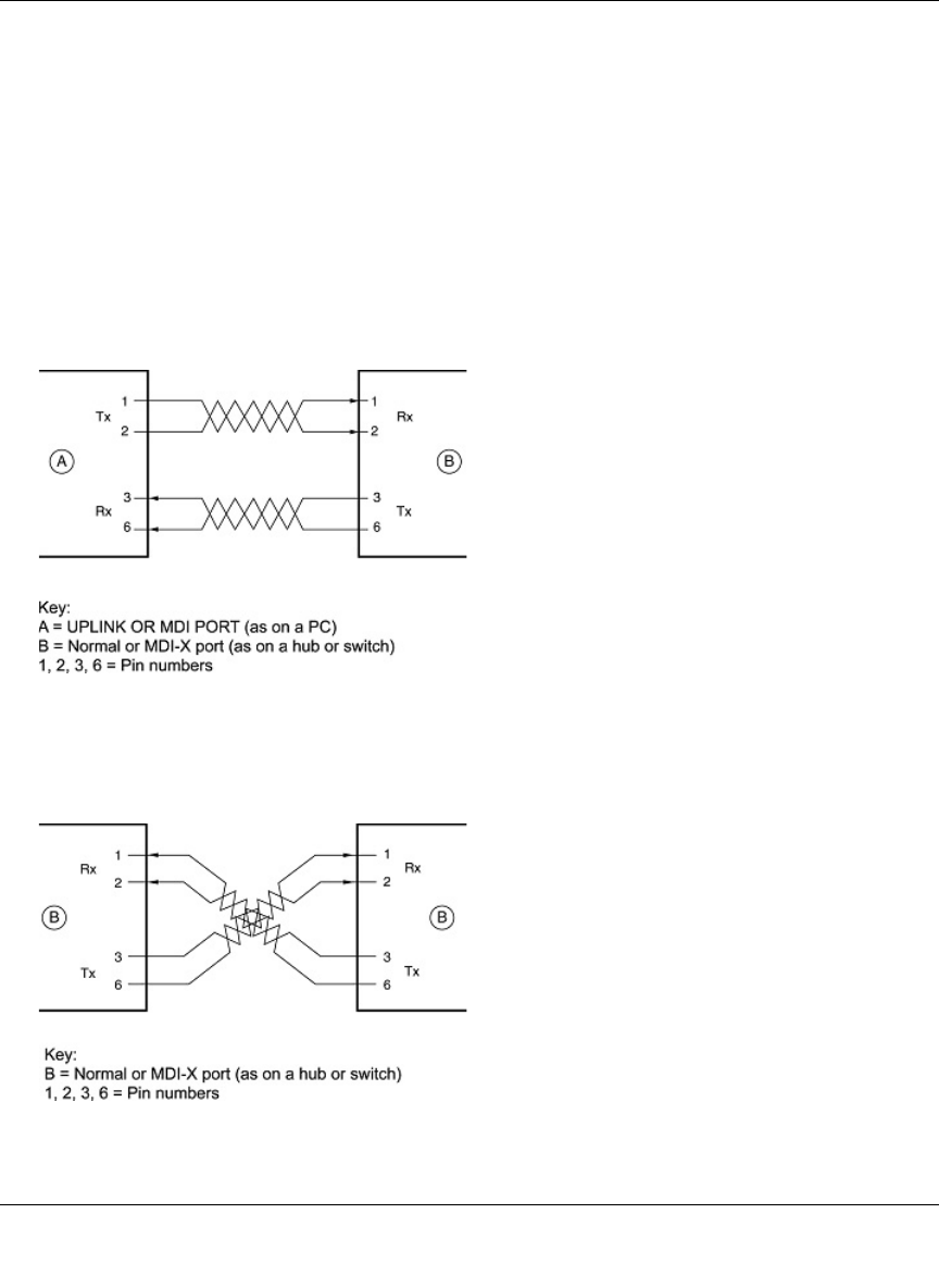
Inside Twisted Pair Cables
For two devices to communicate, the transmitter of each device must be connected to the receiver
of the other device. The crossover function is usually implemented internally as part of the
circuitry in the device. Computers and workstation adapter cards are usually media-dependent
interface ports, called MDI or uplink ports. Most repeaters and switch ports are configured as
media-dependent interfaces with built-in crossover ports, called MDI-X or normal ports. Auto
Uplink technology automatically senses which connection, MDI or MDI-X, is needed and makes
the right connection.
Figure B-4 illustrates straight-through twisted pair cable.
Figure B-4: Straight-Through Twisted-Pair Cable
Figure B-5 illustrates crossover twisted pair cable.
Figure B-5: Crossover Twisted-Pair Cable
Reference Manual for the 54 Mbps Wireless Router WGR614 v6
B-14 Network, Routing, Firewall, and Basics
July 2004 202-10036-01
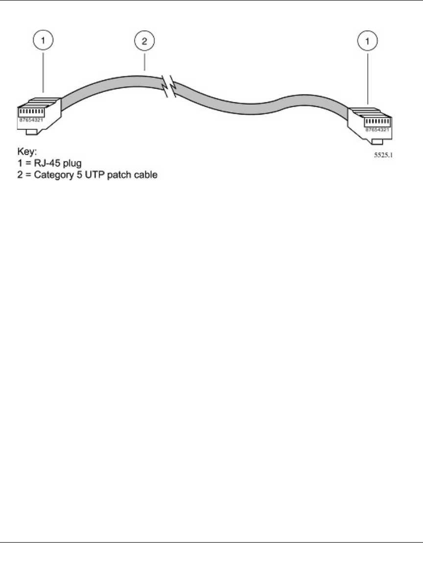
Figure B-6: Category 5 UTP Cable with Male RJ-45 Plug at Each End
Note: Flat “silver satin” telephone cable may have the same RJ-45 plug. However, using telephone
cable results in excessive collisions, causing the attached port to be partitioned or disconnected
from the network.
Uplink Switches, Crossover Cables, and MDI/MDIX Switching
In the wiring table above, the concept of transmit and receive are from the perspective of the
computer, which is wired as Media Dependant Interface (MDI). In this wiring, the computer
transmits on pins 1 and 2. At the hub, the perspective is reversed, and the hub receives on pins 1
and 2. This wiring is referred to as Media Dependant Interface - Crossover (MDI-X).
When connecting a computer to a computer, or a hub port to another hub port, the transmit pair
must be exchanged with the receive pair. This exchange is done by one of two mechanisms. Most
hubs provide an Uplink switch which will exchange the pairs on one port, allowing that port to be
connected to another hub using a normal Ethernet cable. The second method is to use a crossover
cable, which is a special cable in which the transmit and receive pairs are exchanged at one of the
two cable connectors. Crossover cables are often unmarked as such, and must be identified by
comparing the two connectors. Since the cable connectors are clear plastic, it is easy to place them
side by side and view the order of the wire colors on each. On a straight-through cable, the color
order will be the same on both connectors. On a crossover cable, the orange and green pairs will be
exchanged from one connector to the other.

Reference Manual for the 54 Mbps Wireless Router WGR614 v6
Network, Routing, Firewall, and Basics B-15
July 2004 202-10036-01
The WGR614 v6 router incorporates Auto UplinkTM technology (also called MDI/MDIX). Each
LOCAL Ethernet port will automatically sense whether the Ethernet cable plugged into the port
should have a normal connection (e.g. connecting to a computer) or an uplink connection (e.g.
connecting to a router, switch, or hub). That port will then configure itself to the correct
configuration. This feature also eliminates the need to worry about crossover cables, as Auto
UplinkTM will accommodate either type of cable to make the right connection.

Reference Manual for the 54 Mbps Wireless Router WGR614 v6
B-16 Network, Routing, Firewall, and Basics
July 2004 202-10036-01
Preparing Your Network C-1
July 2004 202-10036-01
Appendix C
Preparing Your Network
This appendix describes how to prepare your network to connect to the Internet through the 54
Mbps Wireless Router WGR614 v6 and how to verify the readiness of broadband Internet service
from an Internet service provider (ISP).
What You Need To Use a Router with a Broadband Modem
You need to prepare these three things before you begin:
Cabling and Computer Hardware
To use the WGR614 v6 router on your network, each computer must have an 802.11g or 802.11b
wireless adapter or an installed Ethernet Network Interface Card (NIC) and an Ethernet cable. If
the computer will connect to your network using an Ethernet NIC at 100 Mbps, you must use a
Category 5 (Cat 5) cable such as the one provided with your router. For an explanation of Ethernet
cabling, see “Ethernet Cabling“ on page B-11. The cable or DSL broadband modem must provide
a standard 10 Mbps (10BASE-T) or 100 Mbps (100BASE-Tx) Ethernet interface.
Computer Network Configuration Requirements
The WGR614 v6 includes a built-in Web Configuration Manager. To access the configuration
menus on the WGR614 v6, your must use a Java-enabled Web browser program which supports
HTTP uploads such as Microsoft Internet Explorer or Netscape Navigator. Use Internet Explorer
or Netscape Navigator 4.0 or above.
Note: If an ISP technician configured your computer during the installation of a
broadband modem, or if you configured it using instructions provided by your ISP, you
may need to copy the current configuration information for use in the configuration of
your firewall. Write down this information before reconfiguring your computers. Refer
to “Obtaining ISP Configuration Information for Windows Computers” on page C-21 or
“Obtaining ISP Configuration Information for Macintosh Computers” on page C-22 for
further information.

Reference Manual for the 54 Mbps Wireless Router WGR614 v6
C-2 Preparing Your Network
July 2004 202-10036-01
For the initial setup of your router, you will need to connect a computer to the router. This
computer has to be set to automatically get its TCP/IP configuration from the router via DHCP.
Note: For help with DHCP configuration, please use the Windows TCP/IP Configuration
Tutorials on the NETGEAR 54 Mbps Wireless Router WGR614 v6 Resource CD (230-10091-01),
or in this appendix.
Internet Configuration Requirements
Depending on how your Internet service set up your account, you may need one or more of these
configuration parameters to connect your router to the Internet:
• Host and Domain Names
• ISP Login Name and Password
• ISP Domain Name Server (DNS) Addresses
• Fixed IP Address which is also known as Static IP Address
Where Do I Get the Internet Configuration Parameters?
There are several ways you can gather the required Internet connection information.
• Your Internet service provides all the information needed to connect to the Internet. If you
cannot locate this information, you can ask your Internet service to provide it or you can try
one of the options below.
• If you have a computer already connected using the Internet, you can gather the configuration
information from that computer.
— For Windows 95/98/ME, open the Network control panel, select the TCP/IP entry for the
Ethernet adapter, and click Properties. Record all the settings for each tab page.
— For Windows 2000/XP, open the Local Area Network Connection, select the TCP/IP entry
for the Ethernet adapter, and click Properties. Record all the settings for each tab page.
— For Macintosh computers, record the settings in the TCP/IP or Network control panel.
• You may also refer to the NETGEAR 54 Mbps Wireless Router WGR614 v6 Resource CD
(230-10091-01) for the NETGEAR Router ISP Guide which provides Internet connection
information for many ISPs.
Once you locate your Internet configuration parameters, you may want to record them on the page
below.

Reference Manual for the 54 Mbps Wireless Router WGR614 v6
Preparing Your Network C-3
July 2004 202-10036-01
Record Your Internet Connection Information
Print this page. Fill in the configuration parameters from your Internet Service Provider (ISP).
ISP Login Name: The login name and password are case sensitive and must be entered exactly as
given by your ISP. Some ISPs use your full e-mail address as the login name. The Service Name is
not required by all ISPs. If you connect using a login name and password, enter the following:
Login Name: ______________________________
Password: ____________________________
Service Name: _____________________________
Fixed or Static IP Address: If you have a static IP address, record the following information. For
example, 169.254.141.148 could be a valid IP address.
Fixed or Static Internet IP Address: ______ ______ ______ ______
Gateway IP Address: ______ ______ ______ ______
Subnet Mask: ______ ______ ______ ______
ISP DNS Server Addresses: If you were given DNS server addresses, fill in the following:
Primary DNS Server IP Address: ______ ______ ______ ______
Secondary DNS Server IP Address: ______ ______ ______ ______
Host and Domain Names: Some ISPs use a specific host or domain name like CCA7324-A or
home. If you haven’t been given host or domain names, you can use the following examples as a
guide:
• If your main e-mail account with your ISP is aaa@yyy.com, then use aaa as your host name.
Your ISP might call this your account, user, host, computer, or system name.
• If your ISP’s mail server is mail.xxx.yyy.com, then use xxx.yyy.com as the domain name.
ISP Host Name: _________________________ ISP Domain Name: _______________________
For Wireless Access: See the configuration worksheet at “Information to Gather Before Changing
Basic Wireless Settings“ on page 4-6.
Preparing Your Computers for TCP/IP Networking
Computers access the Internet using a protocol called TCP/IP (Transmission Control Protocol/
Internet Protocol). Each computer on your network must have TCP/IP installed and selected as its
networking protocol. If a Network Interface Card (NIC) is already installed in your computer, then
TCP/IP is probably already installed as well.

Reference Manual for the 54 Mbps Wireless Router WGR614 v6
C-4 Preparing Your Network
July 2004 202-10036-01
Most operating systems include the software components you need for networking with TCP/IP:
•Windows
® 95 or later includes the software components for establishing a TCP/IP network.
• Windows 3.1 does not include a TCP/IP component. You need to purchase a third-party TCP/
IP application package such as NetManage Chameleon.
• Macintosh Operating System 7 or later includes the software components for establishing a
TCP/IP network.
• All versions of UNIX or Linux include TCP/IP components. Follow the instructions provided
with your operating system or networking software to install TCP/IP on your computer.
In your IP network, each computer and the firewall must be assigned a unique IP addresses. Each
computer must also have certain other IP configuration information such as a subnet mask
(netmask), a domain name server (DNS) address, and a default gateway address. In most cases,
you should install TCP/IP so that the computer obtains its specific network configuration
information automatically from a DHCP server during bootup. For a detailed explanation of the
meaning and purpose of these configuration items, refer to “Appendix B, “Network, Routing,
Firewall, and Basics.”
The WGR614 v6 router is shipped preconfigured as a DHCP server. The firewall assigns the
following TCP/IP configuration information automatically when the PCs are rebooted:
• PC or workstation IP addresses—192.168.0.2 through 192.168.0.254
• Subnet mask—255.255.255.0
• Gateway address (the firewall)—192.168.0.1
These addresses are part of the IETF-designated private address range for use in private networks.
Configuring Windows 95, 98, and Me for TCP/IP Networking
As part of the PC preparation process, you need to manually install and configure TCP/IP on each
networked PC. Before starting, locate your Windows CD; you may need to insert it during the
TCP/IP installation process.
Install or Verify Windows Networking Components
To install or verify the necessary components for IP networking:
1. On the Windows taskbar, click the Start button, point to Settings, and then click Control Panel.
Reference Manual for the 54 Mbps Wireless Router WGR614 v6
Preparing Your Network C-5
July 2004 202-10036-01
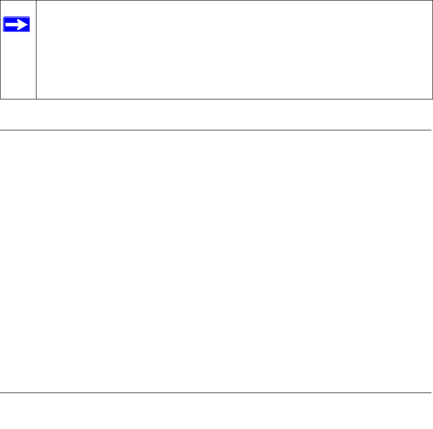
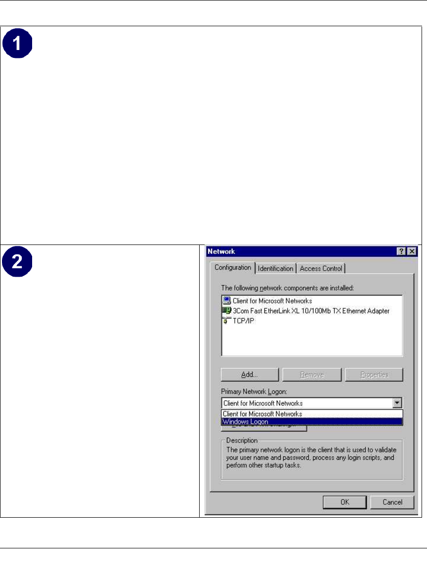
2. Double-click the Network icon.
The Network window opens, which displays a list of installed components:
You must have an Ethernet adapter, the TCP/IP protocol, and Client for Microsoft Networks.
If you need to install a new adapter, follow these steps:
a. Click the Add button.
b. Select Adapter, and then click Add.
c. Select the manufacturer and model of your Ethernet adapter, and then click OK.
If you need TCP/IP:
a. Click the Add button.
b. Select Protocol, and then click Add.
Note: It is not necessary to remove any other network components shown in the
Network window in order to install the adapter, TCP/IP, or Client for Microsoft
Networks.

Reference Manual for the 54 Mbps Wireless Router WGR614 v6
C-6 Preparing Your Network
July 2004 202-10036-01
c. Select Microsoft.
d. Select TCP/IP, and then click OK.
If you need Client for Microsoft Networks:
a. Click the Add button.
b. Select Client, and then click Add.
c. Select Microsoft.
d. Select Client for Microsoft Networks, and then click OK.
3. Restart your PC for the changes to take effect.
Enabling DHCP to Automatically Configure TCP/IP Settings in
Windows 95B, 98, and Me
After the TCP/IP protocol components are installed, each PC must be assigned specific
information about itself and resources that are available on its network. The simplest way to
configure this information is to allow the PC to obtain the information from a DHCP server in the
network.
You will find there are many similarities in the procedures for different Windows systems
when using DHCP to configure TCP/IP.
The following steps will walk you through the configuration process for each of these
versions of Windows.
Reference Manual for the 54 Mbps Wireless Router WGR614 v6
Preparing Your Network C-7
July 2004 202-10036-01
Locate your Network Neighborhood icon.
• If the Network Neighborhood icon is on the Windows desktop, position your mouse
pointer over it and right-click your mouse button.
• If the icon is not on the desktop,
• Click Start on the task bar located at the bottom left of the window.
• Choose Settings, and then Control Panel.
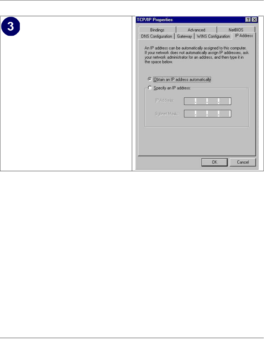
• Locate the Network Neighborhood icon and click on it. This will open the Network
panel as shown below.
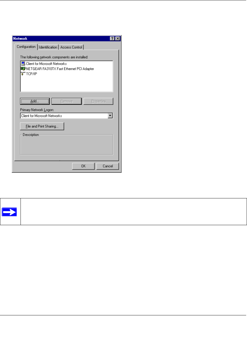
Verify the following settings as shown:
• Client for Microsoft Network exists
• Ethernet adapter is present
• TCP/IP is present
•Primary Network Logon is set to
Windows logon
Click on the Properties button. The
following TCP/IP Properties window will
display.
Reference Manual for the 54 Mbps Wireless Router WGR614 v6
C-8 Preparing Your Network
July 2004 202-10036-01
Selecting Windows’ Internet Access Method
1. On the Windows taskbar, click the Start button, point to Settings, and then click Control Panel.
2. Double-click the Internet Options icon.
3. Select “I want to set up my Internet connection manually” or “I want to connect through a
Local Area Network” and click Next.
4. Select “I want to connect through a Local Area Network” and click Next.
5. Uncheck all boxes in the LAN Internet Configuration screen and click Next.
6. Proceed to the end of the Wizard.
Verifying TCP/IP Properties
After your PC is configured and has rebooted, you can check the TCP/IP configuration using the
utility winipcfg.exe:
1. On the Windows taskbar, click the Start button, and then click Run.
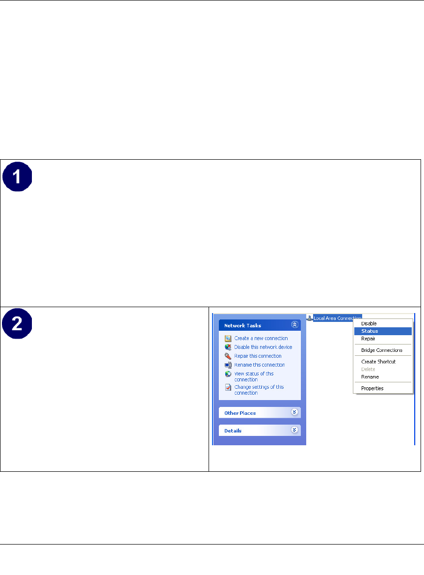
• By default, the IP Address tab is open on
this window.
• Verify the following:
Obtain an IP address automatically is
selected. If not selected, click in the radio
button to the left of it to select it. This
setting is required to enable the DHCP server
to automatically assign an IP address.
• Click OK to continue.
Restart the PC.
Repeat these steps for each PC with this
version of Windows on your network.

Reference Manual for the 54 Mbps Wireless Router WGR614 v6
Preparing Your Network C-9
July 2004 202-10036-01
2. Type winipcfg, and then click OK.
The IP Configuration window opens, which lists (among other things), your IP address, subnet
mask, and default gateway.
3. From the drop-down box, select your Ethernet adapter.
The window is updated to show your settings, which should match the values below if you are
using the default TCP/IP settings that NETGEAR recommends for connecting through a
router or gateway:
• The IP address is between 192.168.0.2 and 192.168.0.254
• The subnet mask is 255.255.255.0
• The default gateway is 192.168.0.1
Configuring Windows NT4, 2000 or XP for IP Networking
As part of the PC preparation process, you may need to install and configure
TCP/IP on each networked PC. Before starting, locate your Windows CD; you may need to insert
it during the TCP/IP installation process.
Install or Verify Windows Networking Components
To install or verify the necessary components for IP networking:
1. On the Windows taskbar, click the Start button, point to Settings, and then click Control Panel.
2. Double-click the Network and Dialup Connections icon.
3. If an Ethernet adapter is present in your PC, you should see an entry for Local Area
Connection. Double-click that entry.
4. Select Properties.
5. Verify that ‘Client for Microsoft Networks’ and ‘Internet Protocol (TCP/IP)’ are present. If
not, select Install and add them.
6. Select ‘Internet Protocol (TCP/IP)’, click Properties, and verify that “Obtain an IP address
automatically is selected.
7. Click OK and close all Network and Dialup Connections windows.
8. Then, restart your PC.
Reference Manual for the 54 Mbps Wireless Router WGR614 v6
C-10 Preparing Your Network
July 2004 202-10036-01
DHCP Configuration of TCP/IP in Windows XP, 2000, or NT4
You will find there are many similarities in the procedures for different Windows systems when
using DHCP to configure TCP/IP.
The following steps will walk you through the configuration process for each of these versions of
Windows.
DHCP Configuration of TCP/IP in Windows XP
Locate your Network Neighborhood icon.
• Select Control Panel from the Windows XP new Start Menu.
• Select the Network Connections icon on the Control Panel. This will take you to the next
step.
• Now the Network Connection window
displays.
The Connections List that shows all the
network connections set up on the PC,
located to the right of the window.
• Right-click on the Connection you will
use and choose Status.
Reference Manual for the 54 Mbps Wireless Router WGR614 v6
Preparing Your Network C-11
July 2004 202-10036-01
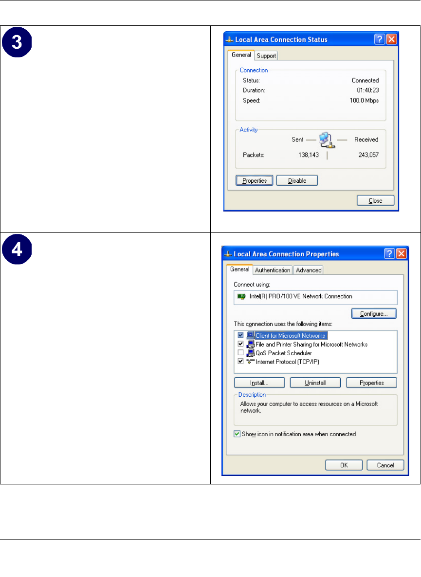
• Now you should be at the Local Area
Network Connection Status window. This
box displays the connection status, duration,
speed, and activity statistics.
• Administrator logon access rights are needed
to use this window.
• Click the Properties button to view details
about the connection.
• The TCP/IP details are presented on the
Support tab page.
• Select Internet Protocol, and click
Properties to view the configuration
information.
Reference Manual for the 54 Mbps Wireless Router WGR614 v6
C-12 Preparing Your Network
July 2004 202-10036-01
DHCP Configuration of TCP/IP in Windows 2000
Once again, after you have installed the network card, TCP/IP for Windows 2000 is configured.
TCP/IP should be added by default and set to DHCP without your having to configure it.
However, if there are problems, follow these steps to configure TCP/IP with DHCP for Windows
2000.
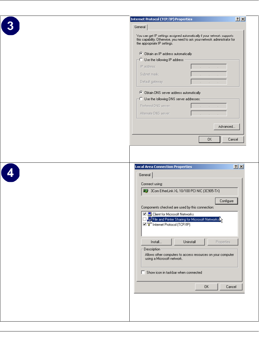
• Verify that the Obtain an IP address
automatically radio button is selected.
• Verify that Obtain DNS server address
automatically radio button is selected.
• Click the OK button.
This completes the DHCP configuration of TCP/
IP in Windows XP.
Repeat these steps for each PC with this version
of Windows on your network.
Reference Manual for the 54 Mbps Wireless Router WGR614 v6
Preparing Your Network C-13
July 2004 202-10036-01
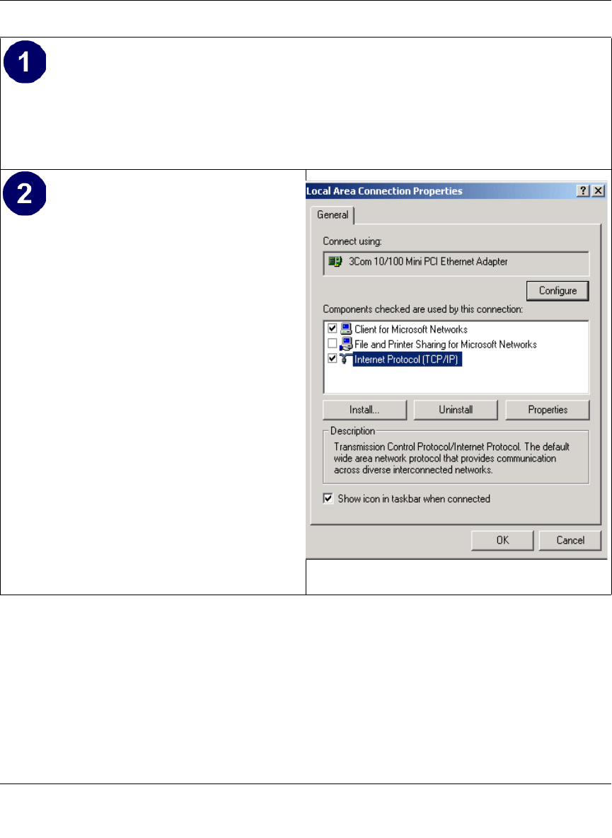
• Click on the My Network Places icon on the Windows desktop. This will bring up a window
called Network and Dial-up Connections.
• Right click on Local Area Connection and select Properties.
•The Local Area Connection Properties
dialog box appears.
• Verify that you have the correct Ethernet
card selected in the Connect using: box.
• Verify that at least the following two items
are displayed and selected in the box of
“Components checked are used by this
connection:”
• Client for Microsoft Networks and
• Internet Protocol (TCP/IP)
• Click OK.
Reference Manual for the 54 Mbps Wireless Router WGR614 v6
C-14 Preparing Your Network
July 2004 202-10036-01
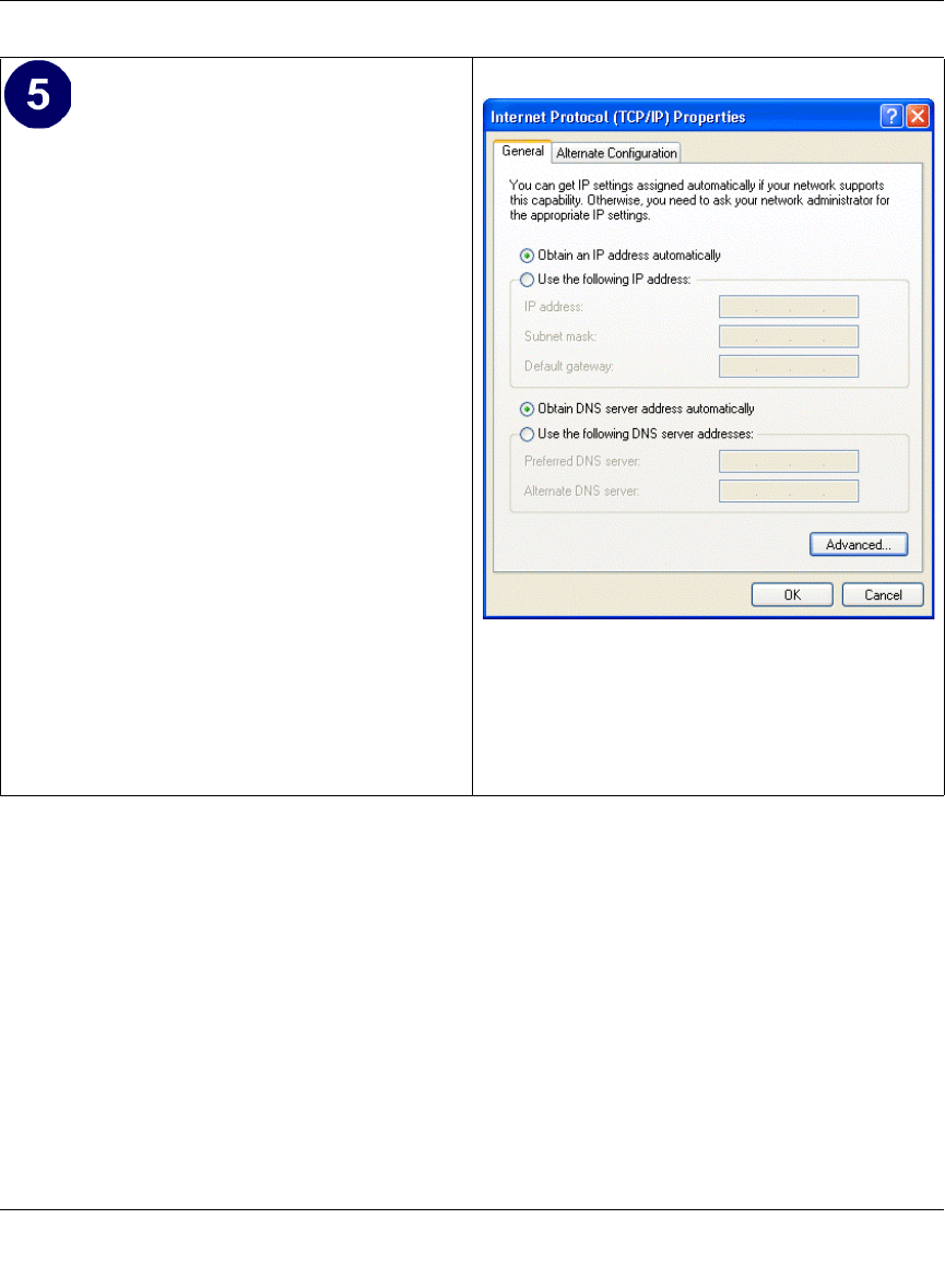
• With Internet Protocol (TCP/IP) selected,
click on Properties to open the Internet
Protocol (TCP/IP) Properties dialogue box.
• Verify that
•Obtain an IP address automatically is
selected.
•Obtain DNS server address
automatically is selected.
• Click OK to return to Local Area
Connection Properties.
• Click OK again to complete the
configuration process for Windows 2000.
Restart the PC.
Repeat these steps for each PC with this version
of Windows on your network.
Reference Manual for the 54 Mbps Wireless Router WGR614 v6
Preparing Your Network C-15
July 2004 202-10036-01
DHCP Configuration of TCP/IP in Windows NT4
Once you have installed the network card, you need to configure the TCP/IP environment for
Windows NT 4.0. Follow this procedure to configure TCP/IP with DHCP in Windows NT 4.0.
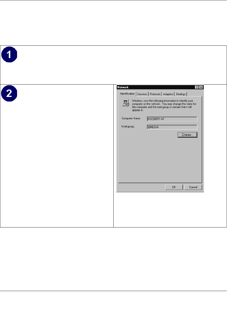
• Choose Settings from the Start Menu, and then select Control Panel.
This will display Control Panel window.
• Double-click the Network icon in the
Control Panel window.
The Network panel will display.
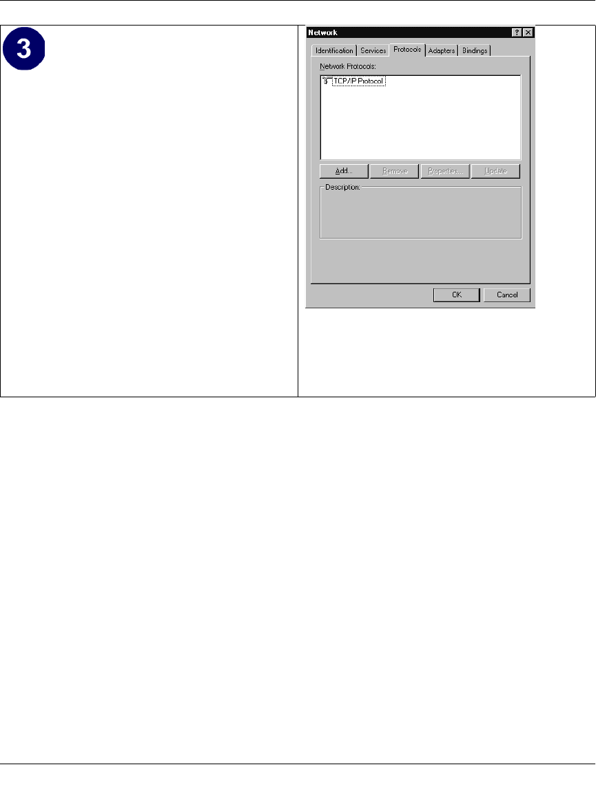
• Select the Protocols tab to continue.
Reference Manual for the 54 Mbps Wireless Router WGR614 v6
C-16 Preparing Your Network
July 2004 202-10036-01
• Highlight the TCP/IP Protocol in the
Network Protocols box, and click on the
Properties button.
Reference Manual for the 54 Mbps Wireless Router WGR614 v6
Preparing Your Network C-17
July 2004 202-10036-01
Verifying TCP/IP Properties for Windows XP, 2000, and NT4
To check your PC’s TCP/IP configuration:
1. On the Windows taskbar, click the Start button, and then click Run.
The Run window opens.
2. Type cmd and then click OK.
A command window opens
3. Type ipconfig /all
Your IP Configuration information will be listed, and should match the values below if you are
using the default TCP/IP settings that NETGEAR recommends for connecting through a
router or gateway:
• The IP address is between 192.168.0.2 and 192.168.0.254
• The subnet mask is 255.255.255.0
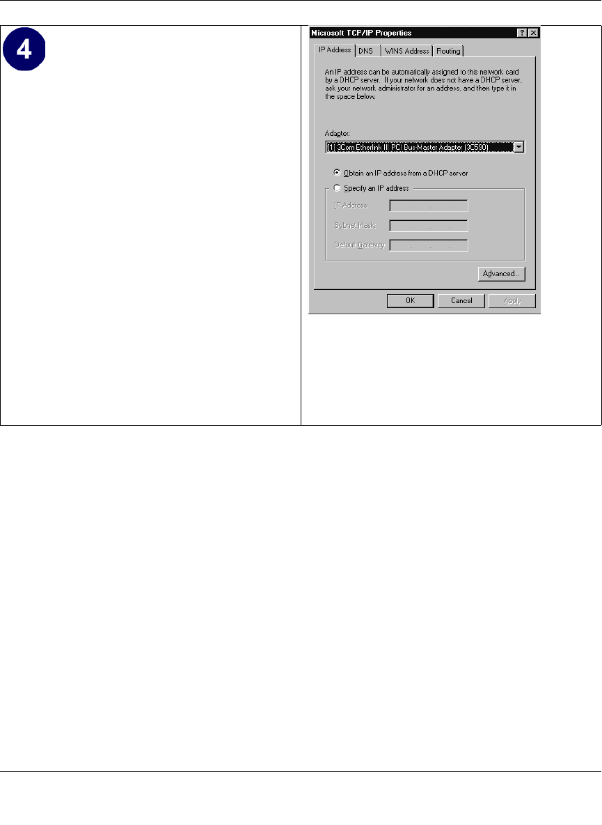
•The TCP/IP Properties dialog box now
displays.
• Click the IP Address tab.
• Select the radio button marked Obtain an IP
address from a DHCP server.
• Click OK. This completes the configuration
of TCP/IP in Windows NT.
Restart the PC.
Repeat these steps for each PC with this version
of Windows on your network.
Reference Manual for the 54 Mbps Wireless Router WGR614 v6
C-18 Preparing Your Network
July 2004 202-10036-01
• The default gateway is 192.168.0.1
4. Type exit
Configuring the Macintosh for TCP/IP Networking
Beginning with Macintosh Operating System 7, TCP/IP is already installed on the Macintosh. On
each networked Macintosh, you will need to configure TCP/IP to use DHCP.
MacOS 8.6 or 9.x
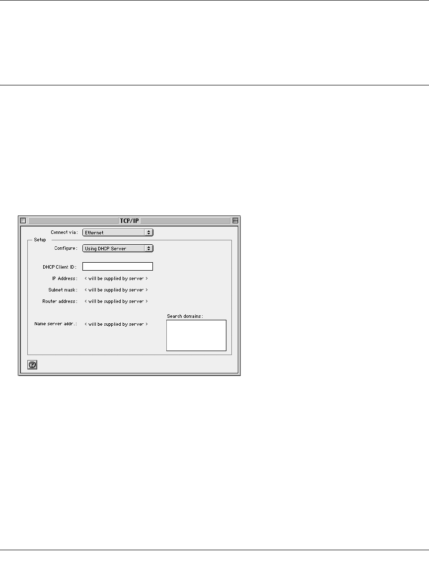
1. From the Apple menu, select Control Panels, then TCP/IP.
The TCP/IP Control Panel opens:
2. From the “Connect via” box, select your Macintosh’s Ethernet interface.
3. From the “Configure” box, select Using DHCP Server.
You can leave the DHCP Client ID box empty.
4. Close the TCP/IP Control Panel.
5. Repeat this for each Macintosh on your network.
MacOS X
1. From the Apple menu, choose System Preferences, then Network.
Reference Manual for the 54 Mbps Wireless Router WGR614 v6
Preparing Your Network C-19
July 2004 202-10036-01
2. If not already selected, select Built-in Ethernet in the Configure list.
3. If not already selected, Select Using DHCP in the TCP/IP tab.
4. Click Save.
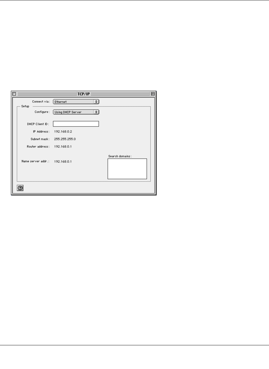
Verifying TCP/IP Properties for Macintosh Computers
After your Macintosh is configured and has rebooted, you can check the TCP/IP configuration by
returning to the TCP/IP Control Panel. From the Apple menu, select Control Panels, then TCP/IP.
The panel is updated to show your settings, which should match the values below if you are using
the default TCP/IP settings that NETGEAR recommends:
• The IP Address is between 192.168.0.2 and 192.168.0.254
• The Subnet mask is 255.255.255.0
• The Router address is 192.168.0.1
If you do not see these values, you may need to restart your Macintosh or you may need to switch
the “Configure” setting to a different option, then back again to “Using DHCP Server”.

Reference Manual for the 54 Mbps Wireless Router WGR614 v6
C-20 Preparing Your Network
July 2004 202-10036-01
Verifying the Readiness of Your Internet Account
For broadband access to the Internet, you need to contract with an Internet service provider (ISP)
for a single-user Internet access account using a cable modem or DSL modem. This modem must
be a separate physical box (not a card) and must provide an Ethernet port intended for connection
to a Network Interface Card (NIC) in a computer. Your firewall does not support a USB-connected
broadband modem.
For a single-user Internet account, your ISP supplies TCP/IP configuration information for one
computer. With a typical account, much of the configuration information is dynamically assigned
when your PC is first booted up while connected to the ISP, and you will not need to know that
dynamic information.
In order to share the Internet connection among several computers, your firewall takes the place of
the single PC, and you need to configure it with the TCP/IP information that the single PC would
normally use. When the firewall’s Internet port is connected to the broadband modem, the firewall
appears to be a single PC to the ISP. The firewall then allows the PCs on the local network to
masquerade as the single PC to access the Internet through the broadband modem. The method
used by the firewall to accomplish this is called Network Address Translation (NAT) or IP
masquerading.
Are Login Protocols Used?
Some ISPs require a special login protocol, in which you must enter a login name and password in
order to access the Internet. If you normally log in to your Internet account by running a program
such as WinPOET or EnterNet, then your account uses PPP over Ethernet (PPPoE).
When you configure your router, you will need to enter your login name and password in the
router’s configuration menus. After your network and firewall are configured, the firewall will
perform the login task when needed, and you will no longer need to run the login program from
your PC. It is not necessary to uninstall the login program.
What Is Your Configuration Information?
More and more, ISPs are dynamically assigning configuration information. However, if your ISP
does not dynamically assign configuration information but instead used fixed configurations, your
ISP should have given you the following basic information for your account:

Reference Manual for the 54 Mbps Wireless Router WGR614 v6
Preparing Your Network C-21
July 2004 202-10036-01
• An IP address and subnet mask
• A gateway IP address, which is the address of the ISP’s router
• One or more domain name server (DNS) IP addresses
• Host name and domain suffix
For example, your account’s full server names may look like this:
mail.xxx.yyy.com
In this example, the domain suffix is xxx.yyy.com.
If any of these items are dynamically supplied by the ISP, your firewall automatically acquires
them.
If an ISP technician configured your PC during the installation of the broadband modem, or if you
configured it using instructions provided by your ISP, you need to copy the configuration
information from your PC’s Network TCP/IP Properties window or Macintosh TCP/IP Control
Panel before reconfiguring your PC for use with the firewall. These procedures are described next.
Obtaining ISP Configuration Information for Windows Computers
As mentioned above, you may need to collect configuration information from your PC so that you
can use this information when you configure the WGR614 v6 router. Following this procedure is
only necessary when your ISP does not dynamically supply the account information.
To get the information you need to configure the firewall for Internet access:
1. On the Windows taskbar, click the Start button, point to Settings, and then click Control Panel.
2. Double-click the Network icon.
The Network window opens, which displays a list of installed components.
3. Select TCP/IP, and then click Properties.
The TCP/IP Properties dialog box opens.
4. Select the IP Address tab.
If an IP address and subnet mask are shown, write down the information. If an address is
present, your account uses a fixed (static) IP address. If no address is present, your account
uses a dynamically-assigned IP address. Click “Obtain an IP address automatically”.
5. Select the Gateway tab.

Reference Manual for the 54 Mbps Wireless Router WGR614 v6
C-22 Preparing Your Network
July 2004 202-10036-01
If an IP address appears under Installed Gateways, write down the address. This is the ISP’s
gateway address. Select the address and then click Remove to remove the gateway address.
6. Select the DNS Configuration tab.
If any DNS server addresses are shown, write down the addresses. If any information appears
in the Host or Domain information box, write it down. Click Disable DNS.
7. Click OK to save your changes and close the TCP/IP Properties dialog box.
You are returned to the Network window.
8. Click OK.
9. Reboot your PC at the prompt. You may also be prompted to insert your Windows CD.
Obtaining ISP Configuration Information for Macintosh
Computers
As mentioned above, you may need to collect configuration information from your Macintosh so
that you can use this information when you configure the WGR614 v6 router. Following this
procedure is only necessary when your ISP does not dynamically supply the account information.
To get the information you need to configure the firewall for Internet access:
1. From the Apple menu, select Control Panels, then TCP/IP.
The TCP/IP Control Panel opens, which displays a list of configuration settings. If the
“Configure” setting is “Using DHCP Server”, your account uses a dynamically-assigned IP
address. In this case, close the Control Panel and skip the rest of this section.
2. If an IP address and subnet mask are shown, write down the information.
3. If an IP address appears under Router address, write down the address. This is the ISP’s
gateway address.
4. If any Name Server addresses are shown, write down the addresses. These are your ISP’s DNS
addresses.
5. If any information appears in the Search domains information box, write it down.
6. Change the “Configure” setting to “Using DHCP Server”.
7. Close the TCP/IP Control Panel.

Reference Manual for the 54 Mbps Wireless Router WGR614 v6
Preparing Your Network C-23
July 2004 202-10036-01
Restarting the Network
Once you’ve set up your computers to work with the firewall, you must reset the network for the
devices to be able to communicate correctly. Restart any computer that is connected to the firewall.
After configuring all of your computers for TCP/IP networking and restarting them, and
connecting them to the local network of your WGR614 v6 router, you are ready to access and
configure the firewall.

Reference Manual for the 54 Mbps Wireless Router WGR614 v6
C-24 Preparing Your Network
July 2004 202-10036-01

Wireless Networking Basics D-1
June 2004 202-10036-01
Appendix D
Wireless Networking Basics
Wireless Networking Overview
The WGR614 v6 router conforms to the Institute of Electrical and Electronics Engineers (IEEE)
802.11g standard for wireless LANs (WLANs). On an 802.11 wireless link, data is encoded using
direct-sequence spread-spectrum (DSSS) technology and is transmitted in the unlicensed radio
spectrum at 2.5GHz. The maximum data rate for the 802.11g wireless link is 54 Mbps, but it will
automatically back down from 54 Mbps when the radio signal is weak or when interference is
detected.
The 802.11 standard is also called Wireless Ethernet or Wi-Fi by the Wireless Ethernet
Compatibility Alliance (WECA, see http://www.wi-fi.net), an industry standard group promoting
interoperability among 802.11 devices. The 802.11 standard offers two methods for configuring a
wireless network - ad hoc and infrastructure.
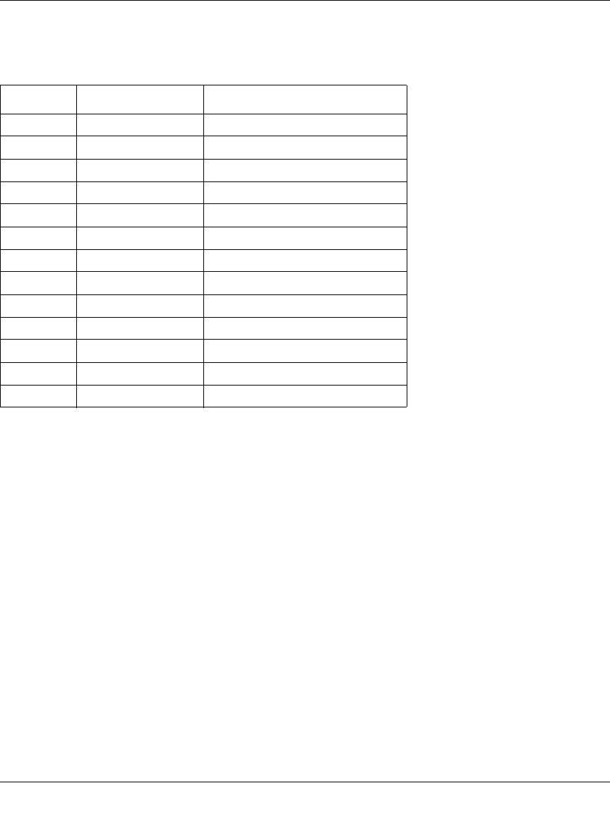
Infrastructure Mode
With a wireless access point, you can operate the wireless LAN in the infrastructure mode. This
mode provides wireless connectivity to multiple wireless network devices within a fixed range or
area of coverage, interacting with wireless nodes via an antenna.
In the infrastructure mode, the wireless access point converts airwave data into wired Ethernet
data, acting as a bridge between the wired LAN and wireless clients. Connecting multiple access
points via a wired Ethernet backbone can further extend the wireless network coverage. As a
mobile computing device moves out of the range of one access point, it moves into the range of
another. As a result, wireless clients can freely roam from one access point domain to another and
still maintain seamless network connection.

Reference Manual for the 54 Mbps Wireless Router WGR614 v6
D-2 Wireless Networking Basics
June 2004 202-10036-01
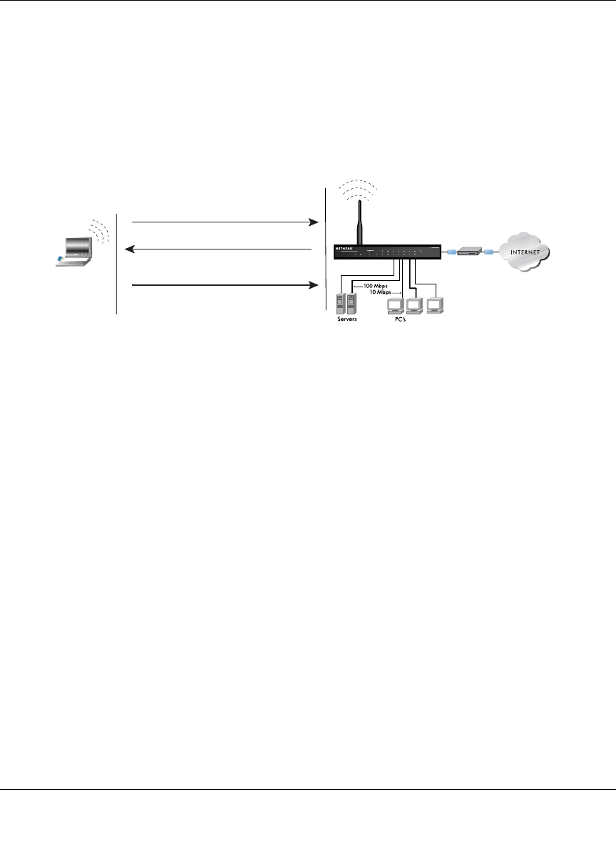
Ad Hoc Mode (Peer-to-Peer Workgroup)
In an ad hoc network, computers are brought together as needed; thus, there is no structure or fixed
points to the network - each node can generally communicate with any other node. There is no
access point involved in this configuration. This mode enables you to quickly set up a small
wireless workgroup and allows workgroup members to exchange data or share printers as
supported by Microsoft networking in the various Windows operating systems. Some vendors also
refer to ad hoc networking as peer-to-peer group networking.
In this configuration, network packets are directly sent and received by the intended transmitting
and receiving stations. As long as the stations are within range of one another, this is the easiest
and least expensive way to set up a wireless network.
Network Name: Extended Service Set Identification (ESSID)
The Extended Service Set Identification (ESSID) is one of two types of Service Set Identification
(SSID). In an ad hoc wireless network with no access points, the Basic Service Set Identification
(BSSID) is used. In an infrastructure wireless network that includes an access point, the ESSID is
used, but may still be referred to as SSID.
An SSID is a thirty-two character (maximum) alphanumeric key identifying the name of the
wireless local area network. Some vendors refer to the SSID as network name. For the wireless
devices in a network to communicate with each other, all devices must be configured with the
same SSID.
Wireless Channels
IEEE 802.11g/b wireless nodes communicate with each other using radio frequency signals in the
ISM (Industrial, Scientific, and Medical) band between 2.4 GHz and 2.5 GHz. Neighboring
channels are 5 MHz apart. However, due to spread spectrum effect of the signals, a node sending
signals using a particular channel will utilize frequency spectrum 12.5 MHz above and below the
center channel frequency. As a result, two separate wireless networks using neighboring channels
(for example, channel 1 and channel 2) in the same general vicinity will interfere with each other.
Applying two channels that allow the maximum channel separation will decrease the amount of
channel cross-talk, and provide a noticeable performance increase over networks with minimal
channel separation.
Reference Manual for the 54 Mbps Wireless Router WGR614 v6
Wireless Networking Basics D-3
June 2004 202-10036-01
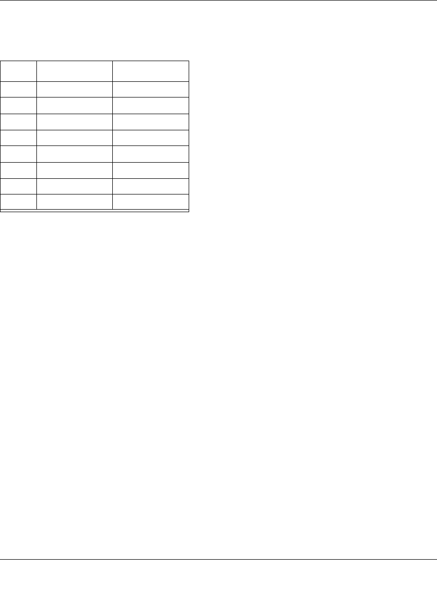
The radio frequency channels used are listed in Table D-1:
Note: The available channels supported by the wireless products in various countries are different.
The preferred channel separation between the channels in neighboring wireless networks is 25
MHz (5 channels). This means that you can apply up to three different channels within your
wireless network. There are only 11 usable wireless channels in the United States. It is
recommended that you start using channel 1 and grow to use channel 6, and 11 when necessary, as
these three channels do not overlap.
Table D-1. 802.11g Radio Frequency Channels
Channel Center Frequency Frequency Spread
1 2412 MHz 2399.5 MHz - 2424.5 MHz
2 2417 MHz 2404.5 MHz - 2429.5 MHz
3 2422 MHz 2409.5 MHz - 2434.5 MHz
4 2427 MHz 2414.5 MHz - 2439.5 MHz
5 2432 MHz 2419.5 MHz - 2444.5 MHz
6 2437 MHz 2424.5 MHz - 2449.5 MHz
7 2442 MHz 2429.5 MHz - 2454.5 MHz
8 2447 MHz 2434.5 MHz - 2459.5 MHz
9 2452 MHz 2439.5 MHz - 2464.5 MHz
10 2457 MHz 2444.5 MHz - 2469.5 MHz
11 2462 MHz 2449.5 MHz - 2474.5 MHz
12 2467 MHz 2454.5 MHz - 2479.5 MHz
13 2472 MHz 2459.5 MHz - 2484.5 MHz

Reference Manual for the 54 Mbps Wireless Router WGR614 v6
D-4 Wireless Networking Basics
June 2004 202-10036-01
WEP Wireless Security
The absence of a physical connection between nodes makes the wireless links vulnerable to
eavesdropping and information theft. To provide a certain level of security, the IEEE 802.11
standard has defined two types of authentication methods, Open System and Shared Key. With
Open System authentication, a wireless computer can join any network and receive any messages
that are not encrypted. With Shared Key authentication, only those computers that possess the
correct authentication key can join the network. By default, IEEE 802.11 wireless devices operate
in an Open System network. Recently, Wi-Fi, the Wireless Ethernet Compatibility Alliance
(http://www.wi-fi.net) developed the Wi-Fi Protected Access (WPA), a new strongly enhanced
Wi-Fi security. WPA will soon be incorporated into the IEEE 802.11 standard. WEP and WPA are
discussed below.
WEP Authentication
The 802.11 standard defines several services that govern how two 802.11 devices communicate.
The following events must occur before an 802.11 Station can communicate with an Ethernet
network through an access point such as the one built in to the WGR614 v6:
1. Turn on the wireless station.
2. The station listens for messages from any access points that are in range.
3. The station finds a message from an access point that has a matching SSID.
4. The station sends an authentication request to the access point.
5. The access point authenticates the station.
6. The station sends an association request to the access point.
7. The access point associates with the station.
8. The station can now communicate with the Ethernet network through the access point.
An access point must authenticate a station before the station can associate with the access point or
communicate with the network. The IEEE 802.11 standard defines two types of WEP
authentication: Open System and Shared Key.
• Open System Authentication allows any device to join the network, assuming that the device
SSID matches the access point SSID. Alternatively, the device can use the “ANY” SSID
option to associate with any available access point within range, regardless of its SSID.
Reference Manual for the 54 Mbps Wireless Router WGR614 v6
Wireless Networking Basics D-5
June 2004 202-10036-01
• Shared Key Authentication requires that the station and the access point have the same WEP
Key to authenticate. These two authentication procedures are described below.
WEP Open System Authentication
This process is illustrated in below.
Figure D-1: 802.11 open system authentication
The following steps occur when two devices use Open System Authentication:
1. The station sends an authentication request to the access point.
2. The access point authenticates the station.
3. The station associates with the access point and joins the network.
INTERNET LOCAL
ACT
12345678
LNK
LNK/ACT
100
Cable/DSL ProSafeWirelessVPN Security Firewall
MODEL FVM318
PWR TEST
WLAN
Enable
Access Point (AP)
1) Authentication request sent to AP
2) AP authenticates
3) Client connects to network
Open System
Authentication Steps
Cable or
DLS modem
Client
attempting
to connect
Reference Manual for the 54 Mbps Wireless Router WGR614 v6
D-6 Wireless Networking Basics
June 2004 202-10036-01
WEP Shared Key Authentication
This process is illustrated in below.
Figure D-2: 802.11 shared key authentication
The following steps occur when two devices use Shared Key Authentication:
1. The station sends an authentication request to the access point.
2. The access point sends challenge text to the station.
3. The station uses its configured 64-bit or 128-bit default key to encrypt the challenge text, and
sends the encrypted text to the access point.
4. The access point decrypts the encrypted text using its configured WEP Key that corresponds
to the station’s default key. The access point compares the decrypted text with the original
challenge text. If the decrypted text matches the original challenge text, then the access point
and the station share the same WEP Key and the access point authenticates the station.
5. The station connects to the network.
If the decrypted text does not match the original challenge text (i.e., the access point and station do
not share the same WEP Key), then the access point will refuse to authenticate the station and the
station will be unable to communicate with either the 802.11 network or Ethernet network.
INTERNET LOCAL
ACT
12345678
LNK
LNK/ACT
100
Cable/DSL ProSafeWirelessVPN Security Firewall
MODEL FVM318
PWR TEST
WLAN
Enable
Access Point1) Authentication
request sent to AP
2) AP sends challenge text
3) Client encrypts
challenge text and
sends it back to AP
4) AP decrypts, and if correct,
authenticates client
5) Client connects to network
Shared Key
Authentication Steps
Cable or
DLS modem
Client
attempting
to connect

Reference Manual for the 54 Mbps Wireless Router WGR614 v6
Wireless Networking Basics D-7
June 2004 202-10036-01
Key Size and Configuration
The IEEE 802.11 standard supports two types of WEP encryption: 40-bit and 128-bit.
The 64-bit WEP data encryption method, allows for a five-character (40-bit) input. Additionally,
24 factory-set bits are added to the forty-bit input to generate a 64-bit encryption key. (The 24
factory-set bits are not user-configurable). This encryption key will be used to encrypt/decrypt all
data transmitted via the wireless interface. Some vendors refer to the 64-bit WEP data encryption
as 40-bit WEP data encryption since the user-configurable portion of the encryption key is 40 bits
wide.
The 128-bit WEP data encryption method consists of 104 user-configurable bits. Similar to the
forty-bit WEP data encryption method, the remaining 24 bits are factory set and not user
configurable. Some vendors allow passphrases to be entered instead of the cryptic hexadecimal
characters to ease encryption key entry.
128-bit encryption is stronger than 40-bit encryption, but 128-bit encryption may not be available
outside of the United States due to U.S. export regulations.
When configured for 40-bit encryption, 802.11 products typically support up to four WEP Keys.
Each 40-bit WEP Key is expressed as 5 sets of two hexadecimal digits (0-9 and A-F). For
example, “12 34 56 78 90” is a 40-bit WEP Key.
When configured for 128-bit encryption, 802.11g products typically support four WEP Keys but
some manufacturers support only one 128-bit key. The 128-bit WEP Key is expressed as 13 sets of
two hexadecimal digits (0-9 and A-F). For example, “12 34 56 78 90 AB CD EF 12 34 56 78 90”
is a 128-bit WEP Key.
Typically, 802.11 access points can store up to four 128-bit WEP Keys but some 802.11 client
adapters can only store one. Therefore, make sure that your 802.11 access and client adapters
configurations match.
Whatever keys you enter for an AP, you must also enter the same keys for the client adapter in the
same order. In other words, WEP key 1 on the AP must match WEP key 1 on the client adapter,
WEP key 2 on the AP must match WEP key 2 on the client adapter, etc.
Note: The AP and the client adapters can have different default WEP Keys as long as the keys are
in the same order. In other words, the AP can use WEP key 2 as its default key to transmit while a
client adapter can use WEP key 3 as its default key to transmit. The two devices will communicate
as long as the AP’s WEP key 2 is the same as the client’s WEP key 2 and the AP’s WEP key 3 is
the same as the client’s WEP key 3.

Reference Manual for the 54 Mbps Wireless Router WGR614 v6
D-8 Wireless Networking Basics
June 2004 202-10036-01
How to Use WEP Parameters
Wired Equivalent Privacy (WEP) data encryption is used when the wireless devices are configured
to operate in Shared Key authentication mode. There are two shared key methods implemented in
most commercially available products, 64-bit and 128-bit WEP data encryption.
Before enabling WEP on an 802.11 network, you must first consider what type of encryption you
require and the key size you want to use. Typically, there are three WEP Encryption options
available for 802.11 products:
1. Do Not Use WEP: The 802.11 network does not encrypt data. For authentication purposes, the
network uses Open System Authentication.
2. Use WEP for Encryption: A transmitting 802.11 device encrypts the data portion of every
packet it sends using a configured WEP Key. The receiving 802.11g device decrypts the data using
the same WEP Key. For authentication purposes, the 802.11g network uses Open System
Authentication.
3. Use WEP for Authentication and Encryption: A transmitting 802.11 device encrypts the data
portion of every packet it sends using a configured WEP Key. The receiving 802.11 device
decrypts the data using the same WEP Key. For authentication purposes, the 802.11 network uses
Shared Key Authentication.
Note: Some 802.11 access points also support Use WEP for Authentication Only (Shared Key
Authentication without data encryption). However, the WGR614 v6 does not offer this option.
WPA Wireless Security
Wi-Fi Protected Access (WPA) is a specification of standards-based, interoperable security
enhancements that increase the level of data protection and access control for existing and future
wireless LAN systems.
The IEEE introduced the WEP as an optional security measure to secure 802.11g (Wi-Fi) WLANs,
but inherent weaknesses in the standard soon became obvious. In response to this situation, the
Wi-Fi Alliance announced a new security architecture in October 2002 that remedies the short
comings of WEP. This standard, formerly known as Safe Secure Network (SSN), is designed to
work with existing 802.11 products and offers forward compatibility with 802.11i, the new
wireless security architecture being defined in the IEEE.
WPA offers the following benefits:

Reference Manual for the 54 Mbps Wireless Router WGR614 v6
Wireless Networking Basics D-9
June 2004 202-10036-01
• Enhanced data privacy
• Robust key management
• Data origin authentication
• Data integrity protection
The Wi-Fi Alliance is now performing interoperability certification testing on Wi-Fi Protected
Access products. Starting August of 2003, all new Wi-Fi certified products will have to support
WPA. NETGEAR will implement WPA on client and access point products and make this
available in the second half of 2003. Existing Wi-Fi certified products will have one year to add
WPA support or they will loose their Wi-Fi certification.
The 802.11i standard is currently in draft form, with ratification due at the end of 2003. While the
new IEEE 802.11i standard is being ratified, wireless vendors have agreed on WPA as an
interoperable interim standard.
How Does WPA Compare to WEP?
WEP is a data encryption method and is not intended as a user authentication mechanism. WPA
user authentication is implemented using 802.1x and the Extensible Authentication Protocol
(EAP). Support for 802.1x authentication is required in WPA. In the 802.11 standard, 802.1x
authentication was optional. For details on EAP specifically, refer to IETF's RFC 2284.
With 802.11 WEP, all access points and client wireless adapters on a particular wireless LAN must
use the same encryption key. A major problem with the 802.11 standard is that the keys are
cumbersome to change. If you don't update the WEP keys often, an unauthorized person with a
sniffing tool can monitor your network for less than a day and decode the encrypted messages.
Products based on the 802.11 standard alone offer system administrators no effective method to
update the keys.
For 802.11, WEP encryption is optional. For WPA, encryption using Temporal Key Integrity
Protocol (TKIP) is required. TKIP replaces WEP with a new encryption algorithm that is stronger
than the WEP algorithm, but that uses the calculation facilities present on existing wireless devices
to perform encryption operations. TKIP provides important data encryption enhancements
including a per-packet key mixing function, a message integrity check (MIC) named Michael, an
extended initialization vector (IV) with sequencing rules, and a re-keying mechanism. Through
these enhancements, TKIP addresses all of known WEP vulnerabilities.

Reference Manual for the 54 Mbps Wireless Router WGR614 v6
D-10 Wireless Networking Basics
June 2004 202-10036-01
How Does WPA Compare to IEEE 802.11i?
WPA will be forward compatible with the IEEE 802.11i security specification currently under
development. WPA is a subset of the current 802.11i draft and uses certain pieces of the 802.11i
draft that are ready to bring to market today, such as 802.1x and TKIP. The main pieces of the
802.11i draft that are not included in WPA are secure IBSS (Ad-Hoc mode), secure fast handoff
(for specialized 802.11 VoIP phones), as well as enhanced encryption protocols such as
AES-CCMP. These features are either not yet ready for market or will require hardware upgrades
to implement.
What are the Key Features of WPA Security?
The following security features are included in the WPA standard:
• WPA Authentication
• WPA Encryption Key Management
– Temporal Key Integrity Protocol (TKIP)
–Michael
message integrity code (MIC)
– AES Support
• Support for a Mixture of WPA and WEP Wireless Clients
These features are discussed below.
WPA addresses most of the known WEP vulnerabilities and is primarily intended for wireless
infrastructure networks as found in the enterprise. This infrastructure includes stations, access
points, and authentication servers (typically RADIUS servers). The RADIUS server holds (or has
access to) user credentials (e.g., user names and passwords) and authenticates wireless users
before they gain access to the network.
The strength WPA comes from an integrated sequence of operations that encompass 802.1X/EAP
authentication and sophisticated key management and encryption techniques. Its major operations
include:
• Network security capability determination. This occurs at the 802.11 level and is
communicated through WPA information elements in Beacon, Probe Response, and (Re)
Association Requests. Information in these elements includes the authentication method
(802.1X or Pre-shared key) and the preferred cipher suite (WEP, TKIP, or AES).

Reference Manual for the 54 Mbps Wireless Router WGR614 v6
Wireless Networking Basics D-11
June 2004 202-10036-01
The primary information conveyed in the Beacon frames is the authentication method and the
cipher suite. Possible authentication methods include 802.1X and Pre-shared key. Pre-shared
key is an authentication method that uses a statically configured pass phrase on both the
stations and the access point. This obviates the need for an authentication server, which in
many home and small office environments will not be available nor desirable. Possible cipher
suites include: WEP, TKIP, and AES (Advanced Encryption Standard). We’ll talk more TKIP
and AES when addressing data privacy below.
• Authentication. EAP over 802.1X is used for authentication. Mutual authentication is gained
by choosing an EAP type supporting this feature and is required by WPA. 802.1X port access
control prevents full access to the network until authentication completes. 802.1X
EAPOL-Key packets are used by WPA to distribute per-session keys to those stations
successfully authenticated.
The supplicant in the station uses the authentication and cipher suite information contained in
the information elements to decide which authentication method and cipher suite to use. For
example, if the access point is using the Pre-shared key method then the supplicant need not
authenticate using full-blown 802.1X. Rather, the supplicant must simply prove to the access
point that it is in possession of the pre-shared key. If the supplicant detects that the service set
does not contain a WPA information element then it knows it must use pre-WPA 802.1X
authentication and key management in order to access the network.
• Key management. WPA features a robust key generation/management system that integrates
the authentication and data privacy functions. Keys are generated after successful
authentication and through a subsequent 4-way handshake between the station and Access
Point (AP).
• Data Privacy (Encryption). Temporal Key Integrity Protocol (TKIP) is used to wrap WEP in
sophisticated cryptographic and security techniques to overcome most of its weaknesses.
• Data integrity. TKIP includes a message integrity code (MIC) at the end of each plaintext
message to ensure messages are not being spoofed.
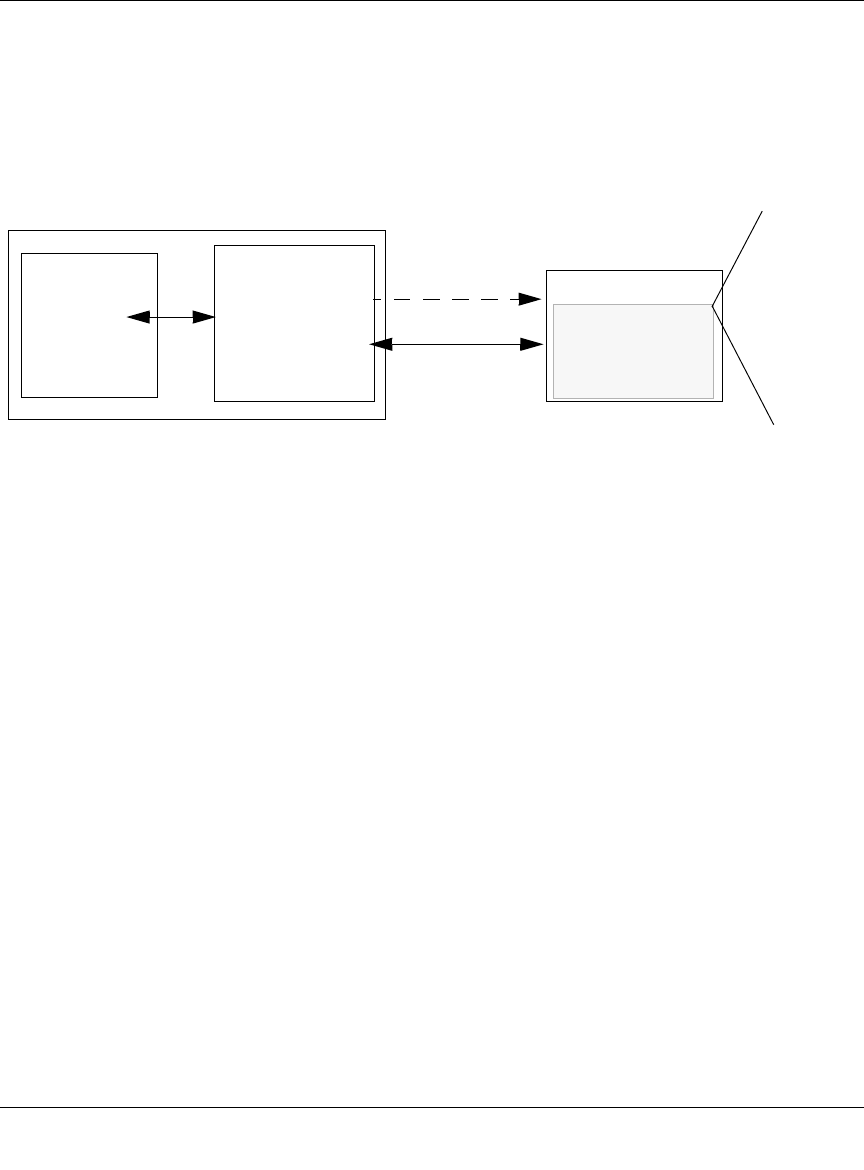
Reference Manual for the 54 Mbps Wireless Router WGR614 v6
D-12 Wireless Networking Basics
June 2004 202-10036-01
WPA Authentication: Enterprise-level User
Authentication via 802.1x/EAP and RADIUS
Figure D-3: WPA Overview
IEEE 802.1x offers an effective framework for authenticating and controlling user traffic to a
protected network, as well as providing a vehicle for dynamically varying data encryption keys via
EAP from a RADIUS server, for example. This framework enables using a central authentication
server, which employs mutual authentication so that a rogue wireless user does not join the
network.
It's important to note that 802.1x doesn't provide the actual authentication mechanisms. When
using 802.1x, the EAP type, such as Transport Layer Security (EAP-TLS) or EAP Tunneled
Transport Layer Security (EAP-TTLS) defines how the authentication takes place.
Note: For environments with a Remote Authentication Dial-In User Service (RADIUS)
infrastructure, WPA supports Extensible Authentication Protocol (EAP). For environments
without a RADIUS infrastructure, WPA supports the use of a preshared key.
Together, these technologies provide a framework for strong user authentication.
Windows XP implements 802.1x natively, and several Netgear switch and wireless access point
products support 802.1x.
WPA
enabled
wireless
client with
“supplicant”
Certificate
Authority
(eg Win
Server,
VeriSign,
etc)
TCP/IP
Ports Closed
Until RADIUS Server
Wired Network with Optional
802.1x Port Based Network
Access Control
WPA enabled
Access Point
using
pre-shared key
or
802.1x
TCP/IP
Ports Opened
After
Authenticated
Wireless LAN
Login
Authentication
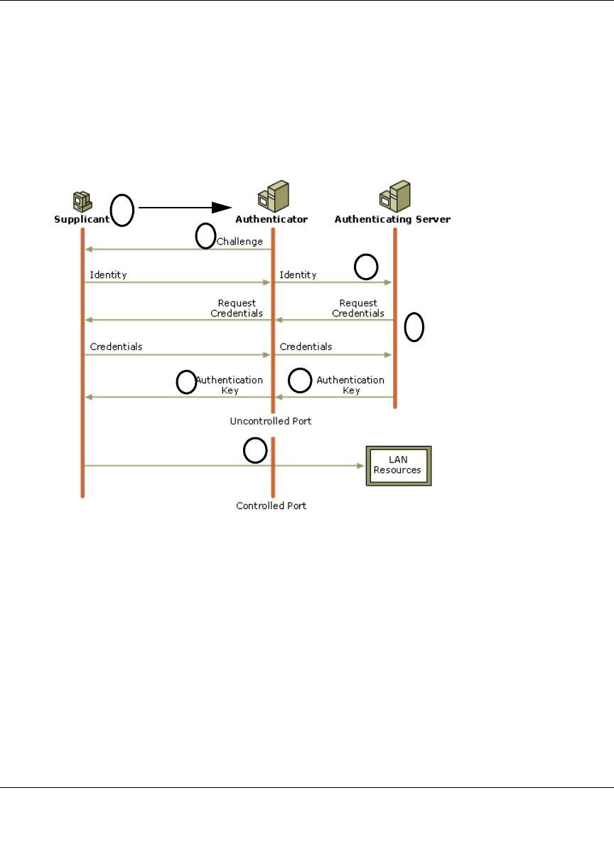
Reference Manual for the 54 Mbps Wireless Router WGR614 v6
Wireless Networking Basics D-13
June 2004 202-10036-01
Figure D-4: 802.1x Authentication Sequence
The AP sends Beacon Frames with WPA information element to the stations in the service set.
Information elements include the required authentication method (802.1x or Pre-shared key) and
the preferred cipher suite (WEP, TKIP, or AES). Probe Responses (AP to station) and Association
Requests (station to AP) also contain WPA information elements.
1. Initial 802.1x communications begin with an unauthenticated supplicant (i.e., client device)
attempting to connect with an authenticator (i.e., 802.11 access point). The client sends an
EAP-start message. This begins a series of message exchanges to authenticate the client.
2. The access point replies with an EAP-request identity message.
1
2
3
4
56
7
Client with a WPA-
enabled wireless
adapter and supplicant
(Win XP, Funk,
Meetinghouse, etc.)
For example, a
WPA-enabled AP
For example, a
RADIUS server

Reference Manual for the 54 Mbps Wireless Router WGR614 v6
D-14 Wireless Networking Basics
June 2004 202-10036-01
3. The client sends an EAP-response packet containing the identity to the authentication server.
The access point responds by enabling a port for passing only EAP packets from the client to
an authentication server located on the wired side of the access point. The access point blocks
all other traffic, such as HTTP, DHCP, and POP3 packets, until the access point can verify the
client's identity using an authentication server (e.g., RADIUS).
4. The authentication server uses a specific authentication algorithm to verify the client's identity.
This could be through the use of digital certificates or some other EAP authentication type.
5. The authentication server will either send an accept or reject message to the access point.
6. The access point sends an EAP-success packet (or reject packet) to the client.
7. If the authentication server accepts the client, then the access point will transition the client's
port to an authorized state and forward additional traffic.
The important part to know at this point is that the software supporting the specific EAP type
resides on the authentication server and within the operating system or application “supplicant”
software on the client devices. The access point acts as a “pass through” for 802.1x messages,
which means that you can specify any EAP type without needing to upgrade an 802.1x-compliant
access point. As a result, you can update the EAP authentication type to such devices as token
cards (Smart Cards), Kerberos, one-time passwords, certificates, and public key authentication or
as newer types become available and your requirements for security change.
WPA Data Encryption Key Management
With 802.1x, the rekeying of unicast encryption keys is optional. Additionally, 802.11 and 802.1x
provide no mechanism to change the global encryption key used for multicast and broadcast
traffic. With WPA, rekeying of both unicast and global encryption keys is required.
For the unicast encryption key, the Temporal Key Integrity Protocol (TKIP) changes the key for
every frame, and the change is synchronized between the wireless client and the wireless access
point (AP). For the global encryption key, WPA includes a facility (the Information Element) for
the wireless AP to advertise the changed key to the connected wireless clients.
If configured to implement dynamic key exchange, the 802.1x authentication server can return
session keys to the access point along with the accept message. The access point uses the session
keys to build, sign and encrypt an EAP key message that is sent to the client immediately after
sending the success message. The client can then use contents of the key message to define
applicable encryption keys. In typical 802.1x implementations, the client can automatically change
encryption keys as often as necessary to minimize the possibility of eavesdroppers having enough
time to crack the key in current use.

Reference Manual for the 54 Mbps Wireless Router WGR614 v6
Wireless Networking Basics D-15
June 2004 202-10036-01
Temporal Key Integrity Protocol (TKIP)
WPA uses TKIP to provide important data encryption enhancements including a per-packet key
mixing function, a message integrity check (MIC) named Michael, an extended initialization
vector (IV) with sequencing rules, and a re-keying mechanism. TKIP also provides for the
following:
• The verification of the security configuration after the encryption keys are determined.
• The synchronized changing of the unicast encryption key for each frame.
• The determination of a unique starting unicast encryption key for each preshared key
authentication.
Michael
With 802.11 and WEP, data integrity is provided by a 32-bit integrity check value (ICV) that is
appended to the 802.11 payload and encrypted with WEP. Although the ICV is encrypted, you can
use cryptanalysis to change bits in the encrypted payload and update the encrypted ICV without
being detected by the receiver.
With WPA, a method known as Michael specifies a new algorithm that calculates an 8-byte
message integrity code (MIC) using the calculation facilities available on existing wireless
devices. The MIC is placed between the data portion of the IEEE 802.11 frame and the 4-byte ICV.
The MIC field is encrypted together with the frame data and the ICV.
Michael also provides replay protection. A new frame counter in the IEEE 802.11 frame is used to
prevent replay attacks.
AES Support
One of the encryption methods supported by WPA beside TKIP is the advanced encryption
standard (AES), although AES support will not be required initially for Wi-Fi certification. This is
viewed as the optimal choice for security conscience organizations, but the problem with AES is
that it requires a fundamental redesign of the NIC’s hardware in both the station and the access
point. TKIP was a pragmatic compromise that allows organizations to deploy better security while
AES capable equipment is being designed, manufactured, and incrementally deployed.

Reference Manual for the 54 Mbps Wireless Router WGR614 v6
D-16 Wireless Networking Basics
June 2004 202-10036-01
Is WPA Perfect?
WPA is not without its vulnerabilities. Specifically, it is susceptible to denial of service (DoS)
attacks. If the access point receives two data packets that fail the Message Integrity Code (MIC)
check within 60 seconds of each other then the network is under an active attack, and as a result,
the access point employs counter measures, which includes disassociating each station using the
access point. This prevents an attacker from gleaning information about the encryption key and
alerts administrators, but it also causes users to lose network connectivity for 60 seconds. More
than anything else, this may just prove that no single security tactic is completely invulnerable.
WPA is a definite step forward in WLAN security over WEP and has to be thought of as a single
part of an end-to-end network security strategy.
Product Support for WPA
Starting in August, 2003, NETGEAR, Inc. wireless Wi-Fi certified products will support the WPA
standard. NETGEAR, Inc. wireless products that had their Wi-Fi certification approved before
August, 2003 will have one year to add WPA so as to maintain their Wi-Fi certification.
WPA requires software changes to the following:
• Wireless access points
• Wireless network adapters
• Wireless client programs
Supporting a Mixture of WPA and WEP Wireless Clients
To support the gradual transition of WEP-based wireless networks to WPA, a wireless AP can
support both WEP and WPA clients at the same time. During the association, the wireless AP
determines which clients use WEP and which clients use WPA. The disadvantage to supporting a
mixture of WEP and WPA clients is that the global encryption key is not dynamic. This is because
WEP-based clients cannot support it. All other benefits to the WPA clients, such as integrity, are
maintained.
However, a mixed mode supporting WPA and non-WPA clients would offer network security that
is no better than that obtained with a non-WPA network, and thus this mode of operation is
discouraged.
Changes to Wireless Access Points
Wireless access points must have their firmware updated to support the following:

Reference Manual for the 54 Mbps Wireless Router WGR614 v6
Wireless Networking Basics D-17
June 2004 202-10036-01
•The new WPA information element
To advertise their support of WPA, wireless APs send the beacon frame with a new 802.11
WPA information element that contains the wireless AP's security configuration (encryption
algorithms and wireless security configuration information).
•The WPA two-phase authentication
Open system, then 802.1x (EAP with RADIUS or preshared key).
•TKIP
•Michael
•AES (optional)
To upgrade your wireless access points to support WPA, obtain a WPA firmware update from your
wireless AP vendor and upload it to your wireless AP.
Changes to Wireless Network Adapters
Wireless network adapters must have their firmware updated to support the following:
•The new WPA information element
Wireless clients must be able to process the WPA information element and respond with a
specific security configuration.
•The WPA two-phase authentication
Open system, then 802.1x (EAP or preshared key).
•TKIP
•Michael
•AES (optional)
To upgrade your wireless network adapters to support WPA, obtain a WPA update from your
wireless network adapter vendor and update the wireless network adapter driver.
For Windows wireless clients, you must obtain an updated network adapter driver that supports
WPA. For wireless network adapter drivers that are compatible with Windows XP (Service Pack 1)
and Windows Server 2003, the updated network adapter driver must be able to pass the adapter's
WPA capabilities and security configuration to the Wireless Zero Configuration service.
Microsoft has worked with many wireless vendors to embed the WPA firmware update in the
wireless adapter driver. So, to update you Windows wireless client, all you have to do is obtain the
new WPA-compatible driver and install the driver. The firmware is automatically updated when
the wireless network adapter driver is loaded in Windows.

Reference Manual for the 54 Mbps Wireless Router WGR614 v6
D-18 Wireless Networking Basics
June 2004 202-10036-01
Changes to Wireless Client Programs
Wireless client programs must be updated to permit the configuration of WPA authentication (and
preshared key) and the new WPA encryption algorithms (TKIP and the optional AES component).
To obtain the Microsoft WPA client program, visit the following Microsoft Web site.

June 2004 202-10036-01
Glossary 1
Glossary
Use the list below to find definitions for technical terms used in this manual.
List of Glossary Terms
10BASE-T
IEEE 802.3 specification for 10 Mbps Ethernet over twisted pair wiring.
100BASE-Tx
IEEE 802.3 specification for 100 Mbps Ethernet over twisted pair wiring.
802.1x
802.1x defines port-based, network access control used to provide authenticated network access and
automated data encryption key management.
The IEEE 802.1x draft standard offers an effective framework for authenticating and controlling user traffic
to a protected network, as well as dynamically varying encryption keys. 802.1x uses a protocol called EAP
(Extensible Authentication Protocol) and supports multiple authentication methods, such as token cards,
Kerberos, one-time passwords, certificates, and public key authentication. For details on EAP specifically,
refer to IETF's RFC 2284.
802.11a
IEEE specification for wireless networking at 54 Mbps operating in unlicensed radio bands over 5GHz.
802.11b
IEEE specification for wireless networking at 11 Mbps using direct-sequence spread-spectrum (DSSS)
technology and operating in the unlicensed radio spectrum at 2.5GHz.
802.11g
A soon to be ratified IEEE specification for wireless networking at 54 Mbps using direct-sequence
spread-spectrum (DSSS) technology and operating in the unlicensed radio spectrum at 2.5GHz. 802.11g is
backwards compatible with 802.11b.
ADSL
Short for asymmetric digital subscriber line, a technology that allows data to be sent over existing copper
telephone lines at data rates of from 1.5 to 9 Mbps when receiving data (known as the downstream rate) and
from 16 to 640 Kbps when sending data (known as the upstream rate).

Reference Manual for the 54 Mbps Wireless Router WGR614 v6
2Glossary
June 2004 202-10036-01
ADSL requires a special ADSL modem. ADSL is growing in popularity as more areas around the world
gain access.
AES
Advanced Encryption Standard, a symmetric 128-bit block data encryption technique.
It is an iterated block cipher with a variable block length and a variable key length. The block length and the
key length can be independently specified to 128, 192 or 256 bits.The U.S government adopted the
algorithm as its encryption technique in October 2000, replacing the DES encryption it used. AES works at
multiple network layers simultaneously.
ARP
Address Resolution Protocol, a TCP/IP protocol used to convert an IP address into a physical address (called
a DLC address), such as an Ethernet address.
A host wishing to obtain a physical address broadcasts an ARP request onto the TCP/IP network. The host
on the network that has the IP address in the request then replies with its physical hardware address. There is
also Reverse ARP (RARP) which can be used by a host to discover its IP address. In this case, the host
broadcasts its physical address and a RARP server replies with the host's IP address.
Auto Uplink
Auto UplinkTM technology (also called MDI/MDIX) eliminates the need to worry about crossover vs.
straight-through Ethernet cables. Auto UplinkTM will accommodate either type of cable to make the right
connection.
Cat 5
Category 5 unshielded twisted pair (UTP) cabling. An Ethernet network operating at 10 Mbits/second
(10BASE-T) will often tolerate low quality cables, but at 100 Mbits/second (10BASE-Tx) the cable must be
rated as Category 5, or Cat 5 or Cat V, by the Electronic Industry Association (EIA).
This rating will be printed on the cable jacket. Cat 5 cable contains eight conductors, arranged in four
twisted pairs, and terminated with an RJ45 type connector. In addition, there are restrictions on maximum
cable length for both 10 and 100 Mbits/second networks.
Denial of Service attack
DoS. A hacker attack designed to prevent your computer or network from operating or communicating.
DHCP
An Ethernet protocol specifying how a centralized DHCP server can assign network configuration
information to multiple DHCP clients. The assigned information includes IP addresses, DNS addresses, and
gateway (router) addresses.
DMZ
A Demilitarized Zone is used by a company that wants to host its own Internet services without sacrificing
unauthorized access to its private network.

Reference Manual for the 54 Mbps Wireless Router WGR614 v6
Glossary 3
June 2004 202-10036-01
The DMZ sits between the Internet and an internal network's line of defense, usually some combination of
firewalls and bastion hosts. Typically, the DMZ contains devices accessible to Internet traffic, such as Web
(HTTP) servers, FTP servers, SMTP (e-mail) servers and DNS servers.
DNS
Short for Domain Name System (or Service), an Internet service that translates domain names into IP
addresses.
Because domain names are alphabetic, they're easier to remember. The Internet however, is really based on
IP addresses. Every time you use a domain name, therefore, a DNS service must translate the name into the
corresponding IP address. For example, the domain name www.example.com might translate to
198.105.232.4. The DNS system is, in fact, its own network. If one DNS server doesn't know how to
translate a particular domain name, it asks another one, and so on, until the correct IP address is returned.
Domain Name
A descriptive name for an address or group of addresses on the Internet. Domain names are of the form of a
registered entity name plus one of a number of predefined top level suffixes such as .com, .edu, .uk, etc. For
example, in the address mail.NETGEAR.com, mail is a server name and NETGEAR.com is the domain.
DoS
A hacker attack designed to prevent your computer or network from operating or communicating.
DSL
Short for digital subscriber line, but is commonly used in reference to the asymmetric version of this
technology (ADSL) that allows data to be sent over existing copper telephone lines at data rates of from 1.5
to 9 Mbps when receiving data (known as the downstream rate) and from 16 to 640 Kbps when sending data
(known as the upstream rate).
ADSL requires a special ADSL modem. ADSL is growing in popularity as more areas around the world
gain access.
DSLAM
DSL Access Multiplexor. The piece of equipment at the telephone company central office that provides the
ADSL signal.
Dynamic Host Configuration Protocol
DHCP. An Ethernet protocol specifying how a centralized DHCP server can assign network configuration
information to multiple DHCP clients. The assigned information includes IP addresses, DNS addresses, and
gateway (router) addresses.
EAP
Extensible Authentication Protocol is a general protocol for authentication that supports multiple
authentication methods.
EAP, an extension to PPP, supports such authentication methods as token cards, Kerberos, one-time
passwords, certificates, public key authentication and smart cards. In wireless communications using EAP, a
user requests connection to a WLAN through an AP, which then requests the identity of the user and

Reference Manual for the 54 Mbps Wireless Router WGR614 v6
4Glossary
June 2004 202-10036-01
transmits that identity to an authentication server such as RADIUS. The server asks the AP for proof of
identity, which the AP gets from the user and then sends back to the server to complete the authentication.
EAP is defined by RFC 2284.
ESP
Encapsulating Security Payload.
ESSID
The Extended Service Set Identification (ESSID) is a thirty-two character (maximum) alphanumeric key
identifying the wireless local area network.
Gateway
A local device, usually a router, that connects hosts on a local network to other networks.
IETF
Internet Engineering Task Force. Working groups of the IETF propose standard protocols and procedures for
the Internet, which are published as RFCs (Request for Comment) at www.ietf.org.
An open international community of network designers, operators, vendors, and researchers concerned with
the evolution of the Internet architecture and the smooth operation of the Internet.
IP
Internet Protocol is the main internetworking protocol used in the Internet. Used in conjunction with the
Transfer Control Protocol (TCP) to form TCP/IP.
IP Address
A four-byte number uniquely defining each host on the Internet, usually written in dotted-decimal notation
with periods separating the bytes (for example, 134.177.244.57).
Ranges of addresses are assigned by Internic, an organization formed for this purpose.
IPX
Short for Internetwork Packet Exchange, a networking protocol used by the Novell NetWare operating
systems.
Like UDP/IP, IPX is a datagram protocol used for connectionless communications. Higher-level protocols,
such as SPX and NCP, are used for additional error recovery services.
ISP
Internet service provider.
Internet Protocol
The main internetworking protocol used in the Internet. Used in conjunction with the Transfer Control
Protocol (TCP) to form TCP/IP.
LAN
A communications network serving users within a limited area, such as one floor of a building.

Reference Manual for the 54 Mbps Wireless Router WGR614 v6
Glossary 5
June 2004 202-10036-01
LDAP
A set of protocols for accessing information directories.
Lightweight Directory Access Protocol
LDAP. A set of protocols for accessing information directories.
LDAP is based on the standards contained within the X.500 standard, but is significantly simpler. And
unlike X.500, LDAP supports TCP/IP, which is necessary for any type of Internet access. Because it's a
simpler version of X.500, LDAP is sometimes called X.500-lite.
local area network
LAN. A communications network serving users within a limited area, such as one floor of a building.
A LAN typically connects multiple personal computers and shared network devices such as storage and
printers. Although many technologies exist to implement a LAN, Ethernet is the most common for
connecting personal computers.
MAC address
The Media Access Control address is a unique 48-bit hardware address assigned to every network interface
card. Usually written in the form 01:23:45:67:89:ab.
Mbps
Megabits per second.
MDI/MDIX
In cable wiring, the concept of transmit and receive are from the perspective of the computer, which is wired
as a Media Dependant Interface (MDI). In MDI wiring, a computer transmits on pins 1 and 2. At the hub,
switch, router, or access point, the perspective is reversed, and the hub receives on pins 1 and 2. This wiring
is referred to as Media Dependant Interface - Crossover (MDI-X). See also AES.
Maximum Receive Unit
The size in bytes of the largest packet that can be sent or received.
Maximum Transmit Unit
The size in bytes of the largest packet that can be sent or received.
Most Significant Bit or Most Significant Byte
MSB. The portion of a number, address, or field that is farthest left when written as a single number in
conventional hexadecimal ordinary notation. The part of the number having the most value.
MRU
The size in bytes of the largest packet that can be sent or received.
MSB
MSB. The portion of a number, address, or field that is farthest left when written as a single number in
conventional hexadecimal ordinary notation. The part of the number having the most value.

Reference Manual for the 54 Mbps Wireless Router WGR614 v6
6Glossary
June 2004 202-10036-01
MTU
The size in bytes of the largest packet that can be sent or received.
NAT
A technique by which several hosts share a single IP address for access to the Internet.
NetBIOS
The Network Basic Input Output System is an application programming interface (API) for sharing services
and information on local-area networks (LANs).
Provides for communication between stations of a network where each station is given a name. These names
are alphanumeric names, up to 16 characters in length.
Network Address Translation
NAT. A technique by which several hosts share a single IP address for access to the Internet.
NIC
Network Interface Card. An adapter in a computer which provides connectivity to a network.
NID
Network Interface Device. The point of demarcation, where the telephone line comes into the house.
packet
A block of information sent over a network. A packet typically contains a source and destination network
address, some protocol and length information, a block of data, and a checksum.
Perfect Forward Secrecy
Perfect Forward Secrecy (PFS) provides additional security by means of a Diffie-Hellman shared secret
value. With PFS, if one key is compromised, previous and subsequent keys are secure because they are not
derived from previous keys.
PKIX
PKIX. The most widely used standard for defining digital certificates.
Point-to-Point Protocol
PPP. A protocol allowing a computer using TCP/IP to connect directly to the Internet.
PPP
A protocol allowing a computer using TCP/IP to connect directly to the Internet.
PPPoA
PPPoA. PPP over ATM is a protocol for connecting remote hosts to the Internet over an always-on
connection by simulating a dial-up connection.

Reference Manual for the 54 Mbps Wireless Router WGR614 v6
Glossary 7
June 2004 202-10036-01
PPPoE
PPPoE. PPP over Ethernet is a protocol for connecting remote hosts to the Internet over an always-on
connection by simulating a dial-up connection.
PPP over ATM
PPPoA. PPP over ATM is a protocol for connecting remote hosts to the Internet over an always-on
connection by simulating a dial-up connection.
PPP over Ethernet
PPPoE. PPP over Ethernet is a protocol for connecting remote hosts to the Internet over an always-on
connection by simulating a dial-up connection.
PPTP
Point-to-Point Tunneling Protocol. A method for establishing a virtual private network (VPN) by embedding
Microsoft’s network protocol into Internet packets.
PSTN
Public Switched Telephone Network.
RADIUS
Short for Remote Authentication Dial-In User Service, RADIUS is an authentication system.
Using RADIUS, you must enter your user name and password before gaining access to a network. This
information is passed to a RADIUS server, which checks that the information is correct, and then authorizes
access. Though not an official standard, the RADIUS specification is maintained by a working group of the
IETF.
RFC
Request For Comment. Refers to documents published by the Internet Engineering Task Force (IETF)
proposing standard protocols and procedures for the Internet. RFCs can be found at www.ietf.org.
RIP
A protocol in which routers periodically exchange information with one another so that they can determine
minimum distance paths between sources and destinations.
router
A device that forwards data between networks. An IP router forwards data based on IP source and
destination addresses.
Routing Information Protocol
RIP. A protocol in which routers periodically exchange information with one another so that they can
determine minimum distance paths between sources and destinations.

Reference Manual for the 54 Mbps Wireless Router WGR614 v6
8Glossary
June 2004 202-10036-01
SSID
A Service Set Identification is a thirty-two character (maximum) alphanumeric key identifying a wireless
local area network. For the wireless devices in a network to communicate with each other, all devices must
be configured with the same SSID.
This is typically the configuration parameter for a wireless PC card. It corresponds to the ESSID in the
wireless Access Point and to the wireless network name. See also Wireless Network Name and ESSID.
Subnet Mask
A mask used to determine what subnet an IP address belongs to. Subnetting enables a network administrator
to further divide an IP address into two or more subnets.
An IP address has two components, the network address and the host address. For example, consider the IP
address 150.215.017.009. Assuming this is part of a Class B network, the first two numbers (150.215)
represent the Class B network address, and the second two numbers (017.009) identify a particular host on
this network.
Subnetting enables the network administrator to further divide the host part of the address into two or more
subnets. In this case, a part of the host address is reserved to identify the particular subnet. This is easier to
see if we show the IP address in binary format. The full address is: 10010110.11010111.00010001.00001001
The Class B network part is: 10010110.11010111
and the host address is 00010001.00001001
If this network is divided into 14 subnets, however, then the first 4 bits of the host address (0001) are
reserved for identifying the subnet.
The subnet mask is the network address plus the bits reserved for identifying the subnetwork. (By
convention, the bits for the network address are all set to 1, though it would also work if the bits were set
exactly as in the network address.) In this case, therefore, the subnet mask would be
11111111.11111111.11110000.00000000. It's called a mask because it can be used to identify the subnet to
which an IP address belongs by performing a bitwise AND operation on the mask and the IP address. The
result is the subnetwork address: Subnet Mask 255.255.240.000 11111111.11111111.11110000.00000000
IP Address 150.215.017.009 10010110.11010111.00010001.00001001
Subnet Address 150.215.016.000 10010110.11010111.00010000.00000000
The subnet address, therefore, is 150.215.016.000.
TCP/IP
The main internetworking protocols used in the Internet. The Internet Protocol (IP) used in conjunction with
the Transfer Control Protocol (TCP) form TCP/IP.
TLS
Short for Transport Layer Security, TLS is a protocol that guarantees privacy and data integrity between
client/server applications communicating over the Internet.
The TLS protocol is made up of two layers. The TLS Record Protocol ensures that a connection is private by
using symmetric data encryption and ensures that the connection is reliable. The second TLS layer is the
TLS Handshake Protocol, which allows authentication between the server and client and the negotiation of

Reference Manual for the 54 Mbps Wireless Router WGR614 v6
Glossary 9
June 2004 202-10036-01
an encryption algorithm and cryptographic keys before data is transmitted or received. Based on Netscape’s
SSL 3.0, TLS supercedes and is an extension of SSL. TLS and SSL are not interoperable.
Universal Plug and Play
UPnP. A networking architecture that provides compatibility among networking technology. UPnP
compliant routers provide broadband users at home and small businesses with a seamless way to participate
in online games, videoconferencing and other peer-to-peer services.
UTP
Unshielded twisted pair is the cable used by 10BASE-T and 100BASE-Tx Ethernet networks.
WAN
Wide Area Network. A long distance link used to extend or connect remotely located local area networks.
The Internet is a large WAN.
WEB Proxy Server
A Web proxy server is a specialized HTTP server that allows clients access to the Internet from behind a
firewall.
The proxy server listens for requests from clients within the firewall and forwards these requests to remote
Internet servers outside the firewall. The proxy server reads responses from the external servers and then
sends them to internal client clients.
WEP
Wired Equivalent Privacy is a data encryption protocol for 802.11b wireless networks.
All wireless nodes and access points on the network are configured with a 64-bit or 128-bit Shared Key for
data encryption.
wide area network
WAN. A long distance link used to extend or connect remotely located local area networks. The Internet is a
large WAN.
Wi-Fi
A trade name for the 802.11b wireless networking standard, given by the Wireless Ethernet Compatibility
Alliance (WECA, see http://www.wi-fi.net), an industry standards group promoting interoperability among
802.11b devices.
Windows Internet Naming Service
WINS. Windows Internet Naming Service is a server process for resolving Windows-based computer names
to IP addresses.
If a remote network contains a WINS server, your Windows PCs can gather information from that WINS
server about its local hosts. This allows your PCs to browse that remote network using the Windows
Network Neighborhood feature.

Reference Manual for the 54 Mbps Wireless Router WGR614 v6
10 Glossary
June 2004 202-10036-01
WINS
WINS. Windows Internet Naming Service is a server process for resolving Windows-based computer names
to IP addresses.
Wireless Network Name (SSID)
Wireless Network Name (SSID) is the name assigned to a wireless network. This is the same as the SSID or
ESSID configuration parameter.
WPA
Wi-Fi Protected Access (WPA) is a specification of standards-based, interoperable security enhancements
that increase the level of data protection and access control for existing and future wireless LAN systems.

Index 1
Numerics
802.11b D-1
A
Account Name 3-14, 6-2
Address Resolution Protocol B-8
ad-hoc mode D-2
Auto MDI/MDI-X B-15, G-2
Auto Uplink 2-3, B-15, G-2
B
backup configuration 6-6
Basic Wireless Connectivity 4-7
Basic Wireless Settings 4-11
BSSID D-2
C
Cabling B-11
Cat5 cable B-12, C-1, G-2
configuration
automatic by DHCP 2-4
backup 6-6
erasing 6-7
restore 6-8
router, initial 3-1
content filtering 2-2, 5-1
conventions
typography 1-1
crossover cable 2-3, 8-2, B-14, B-15, G-2
customer support 1-iii
D
date and time 8-8
Daylight Savings Time 8-8
daylight savings time 5-8
Default DMZ Server 7-8
Denial of Service (DoS) protection 2-2
denial of service attack B-11
DHCP B-10
DHCP Client ID C-18
DMZ 2-3, 7-4, 7-8
DMZ Server 7-8
DNS Proxy 2-4
DNS server C-22
DNS, dynamic 7-13
domain C-22
Domain Name 3-14
domain name server (DNS) B-9
DoS attack B-11
Dynamic DNS 7-13
E
EnterNet C-20
erase configuration 6-7
ESSID 4-8, D-2
Ethernet 2-3
Ethernet cable B-11
F
factory settings, restoring 6-7
firewall features 2-2
Flash memory, for firmware upgrade 2-2
Index

2Index
front panel 2-6, 2-7
fully qualified domain name (FQDN) 4-5
G
gateway address C-22
H
Half Life 7-6
host name 3-14
I
IANA
contacting B-2
IETF B-1
Web site address B-7
infrastructure mode D-2
installation 2-4
Internet account
address information C-20
establishing C-20
IP addresses C-21, C-22
and NAT B-7
and the Internet B-2
assigning B-2, B-9
auto-generated 8-3
private B-7
translating B-9
IP configuration by DHCP B-10
IP networking
for Macintosh C-18
for Windows C-4, C-9
K
KALI 7-6
L
LAN IP Setup Menu 7-10
LEDs
troubleshooting 8-2
log
sending 5-7
log entries 5-6
Logout 3-11, 3-12
M
MAC address 8-7, B-8
spoofing 3-14, 8-5
Macintosh C-21
configuring for IP networking C-18
DHCP Client ID C-18
Obtaining ISP Configuration Information C-22
masquerading C-20
MDI/MDI-X B-15, G-2
MDI/MDI-X wiring B-14, G-5
metric 7-15
N
NAT C-20
NAT. See Network Address Translation
netmask
translation table B-6
Network Address Translation 2-4, B-7, C-20
Network Time Protocol 5-8, 8-8
NTP 5-8, 8-8
O
Open System authentication D-4
P
package contents 2-5
Passphrase 4-4, 4-6, 4-10, 4-11
passphrase 2-2
password
restoring 8-7
PC, using to configure C-23
ping 7-8
placement 4-1
port filtering 5-3

Index 3
Port Forwarding 7-3
port forwarding behind NAT B-8
Port Forwarding Menu 7-2, 7-3, 7-4, 7-5
port numbers 5-3
PPP over Ethernet 2-4, C-20
PPPoE C-20
Primary DNS Server 3-14
protocols
Address Resolution B-8
DHCP B-10
Routing Information 2-4, B-2
support 2-2
publications, related B-1
Q
Quake 7-6
R
range 4-1
rear panel 2-7
remote management 7-16
reserved IP adresses 7-12
restore configuration 6-8
restore factory settings 6-7
Restrict Wireless Access by MAC Address 4-11
RFC
1466 B-7, B-9
1597 B-7, B-9
1631 B-7, B-9
finding B-7
RIP (Router Information Protocol) 7-11
router concepts B-1
Router Status 6-1
Routing Information Protocol 2-4, B-2
S
Scope of Document 1-1
Secondary DNS Server 3-14
security 2-1, 2-3
service numbers 5-4
Setup Wizard 3-1
Shared Key authentication D-4
SMTP 5-8
spoof MAC address 8-5
SSID 2-8, 4-3, 4-8, 4-9, D-2
stateful packet inspection 2-2, B-11
Static Routes 7-13
Status Light 2-6
subnet addressing B-4
subnet mask B-5, C-21, C-22
T
TCP/IP
configuring C-1
network, troubleshooting 8-5
TCP/IP properties
verifying for Macintosh C-19
verifying for Windows C-8, C-17
time of day 8-8
time zone 5-8
time-stamping 5-8
troubleshooting 8-1
Trusted Host 5-3
U
Uplink switch B-14
USB C-20
W
WAN 7-7
WEP 2-8, D-8
Wi-Fi D-1, D-4
Windows, configuring for IP routing C-4, C-9
winipcfg utility C-8
WinPOET C-20
Wired Equivalent Privacy. See WEP
Wireless Access C-3
