Netgear orporated 05200007 11g 8 port wireless VPN router User Manual FullManual
Netgear Incorporated 11g 8 port wireless VPN router FullManual
UserManual.wiki
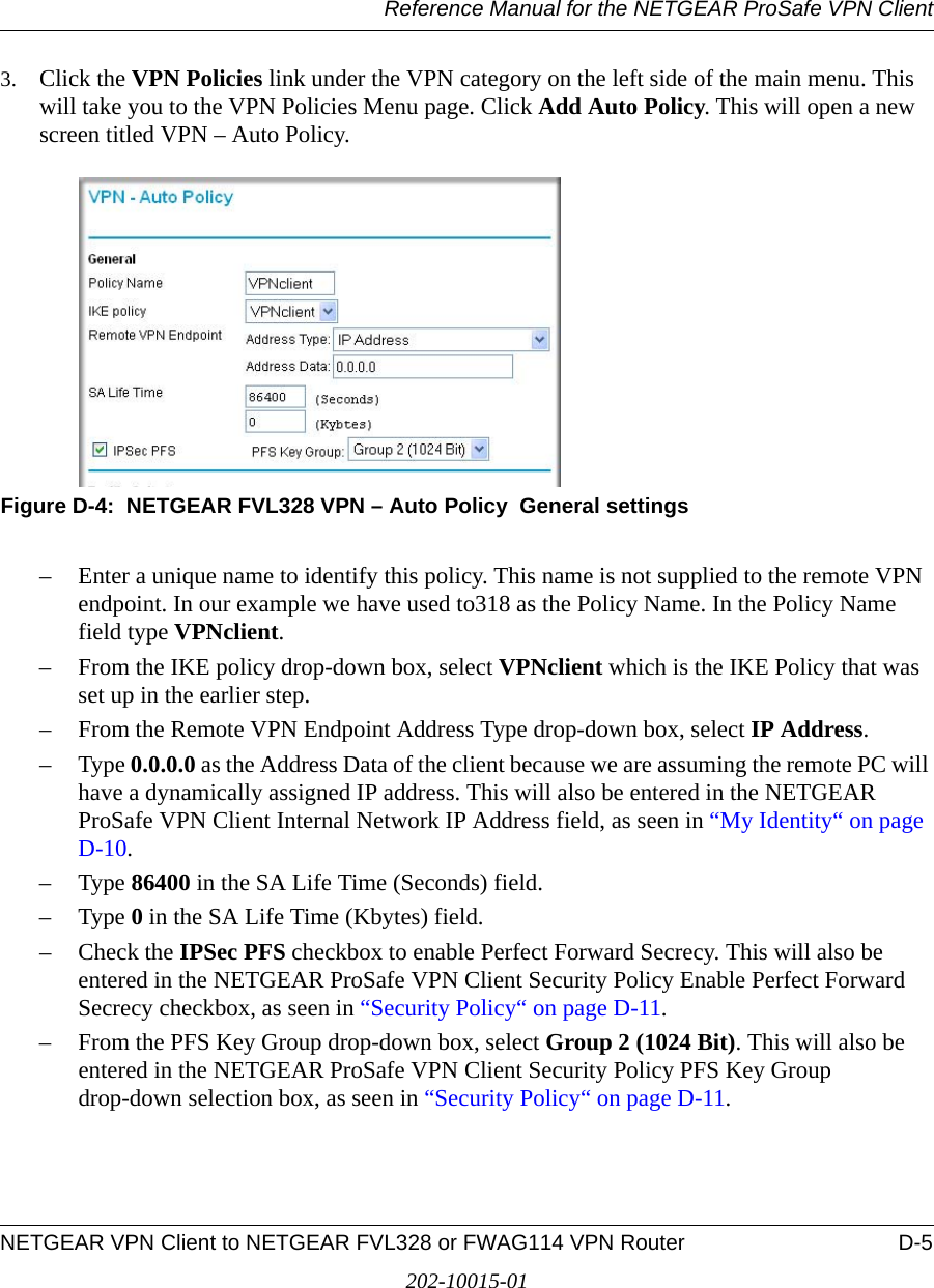
>
Netgear orporated
>
05200007 User Manual
User Manual
Navigation menu
Upload a User Manual
Namespaces
Wiki Guide
HTML
PDF
Info
Views
User Manual
Discussion / Help
Navigation
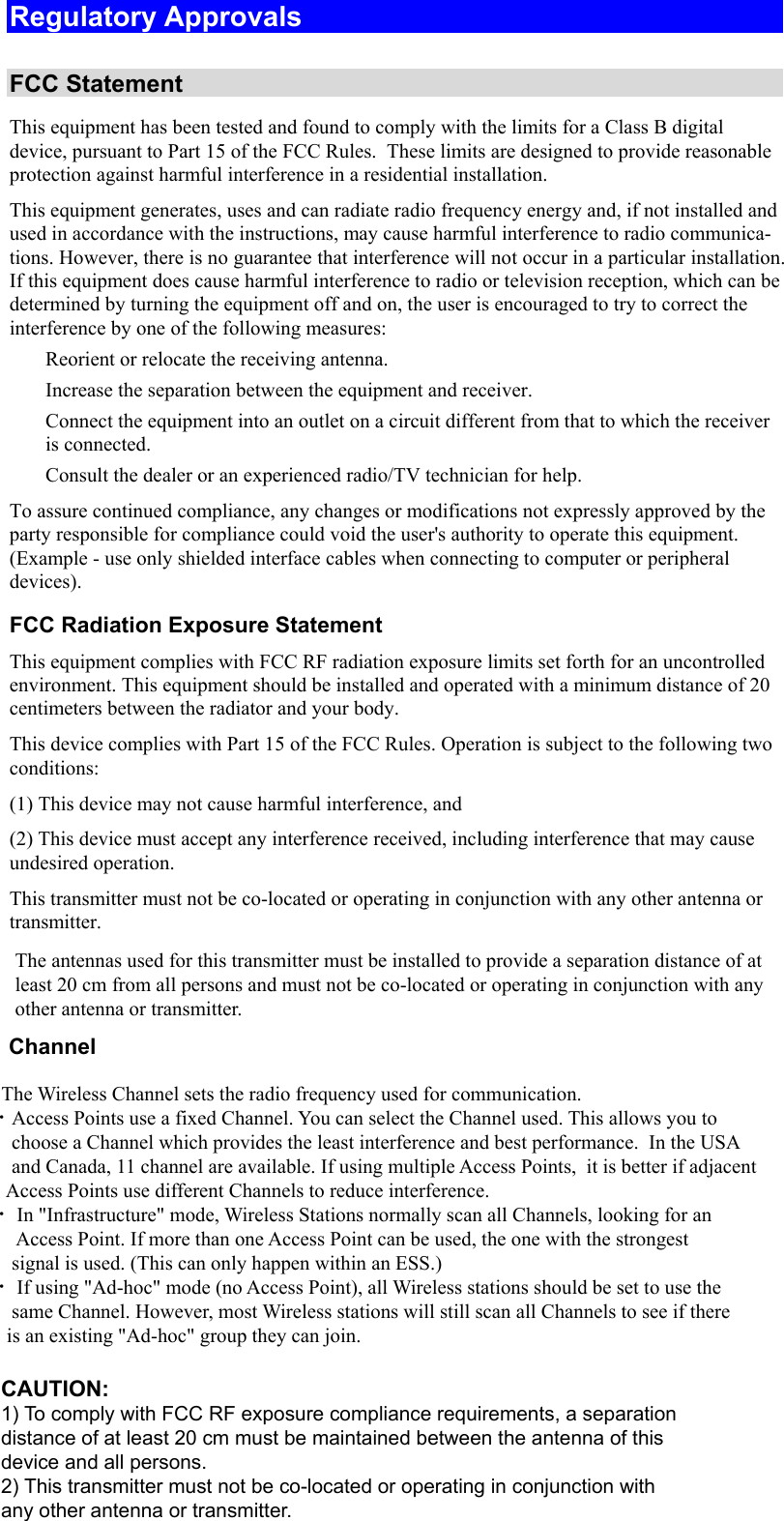
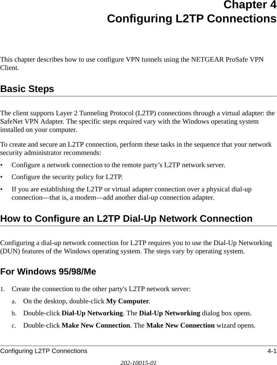
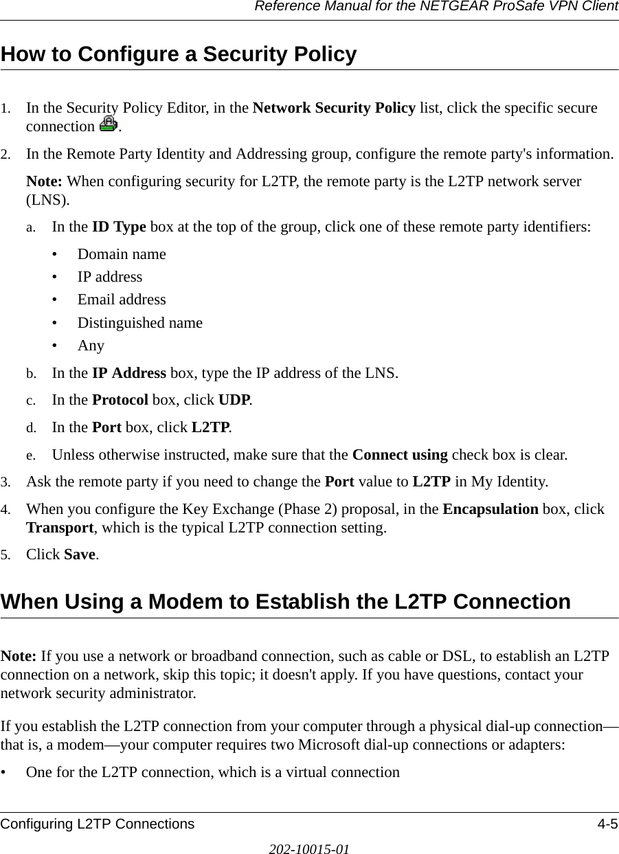
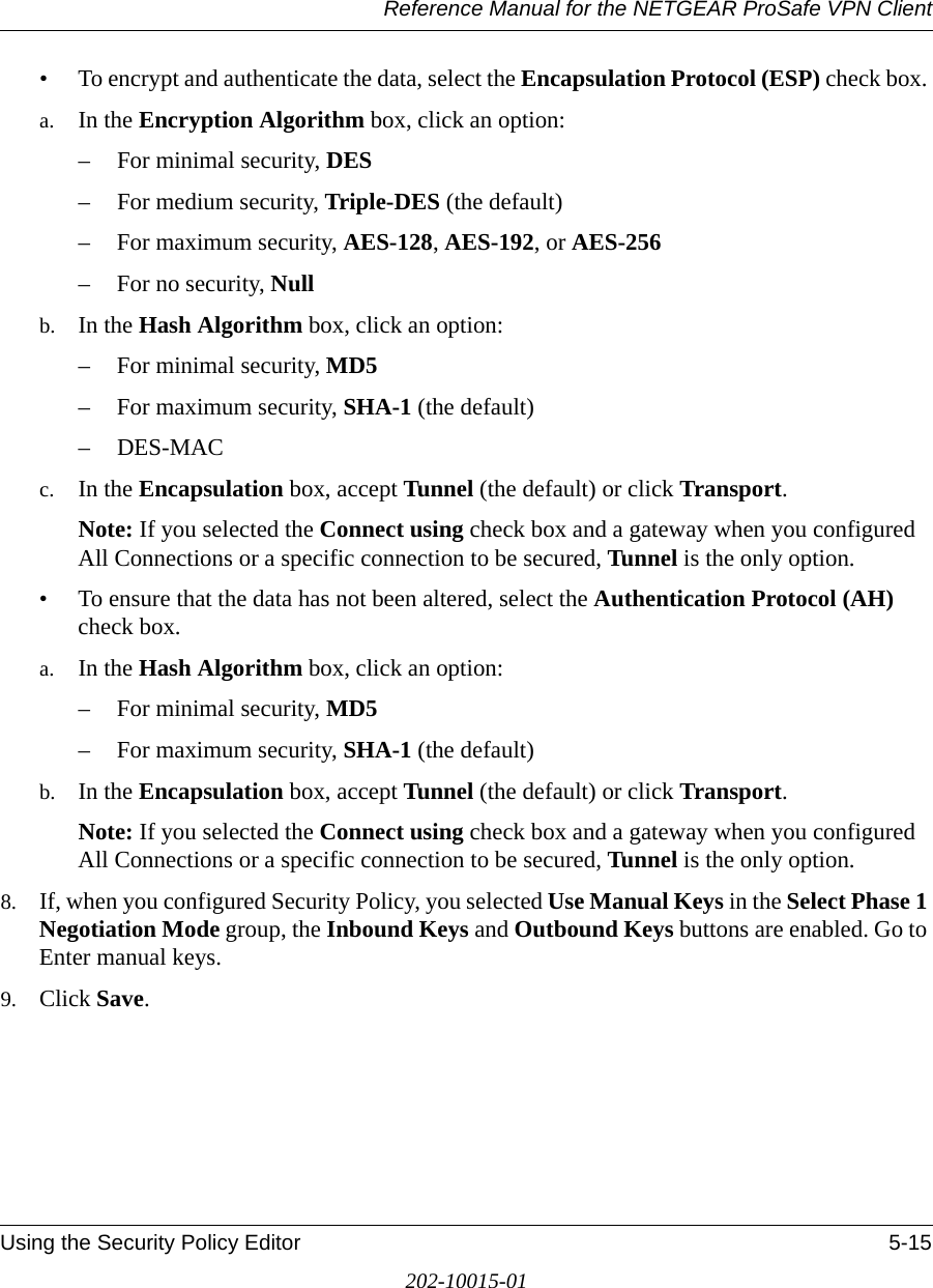

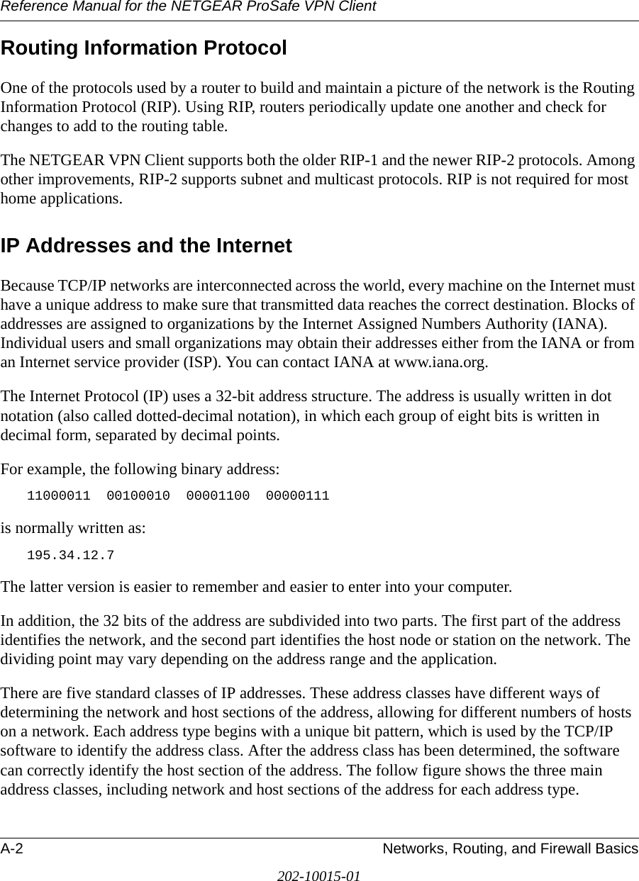
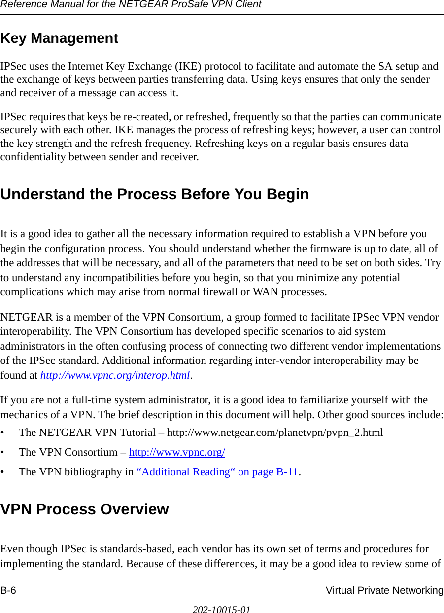
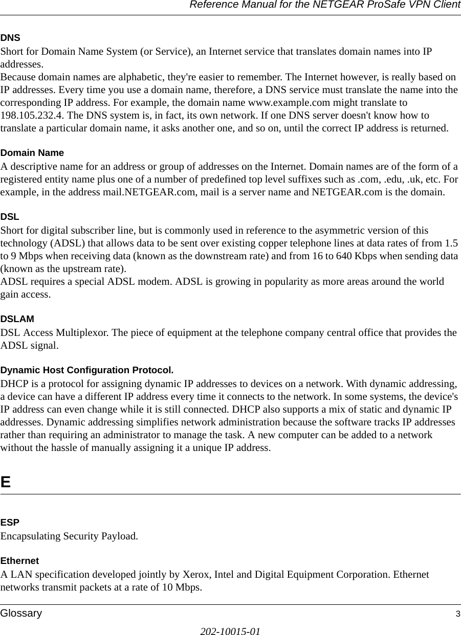
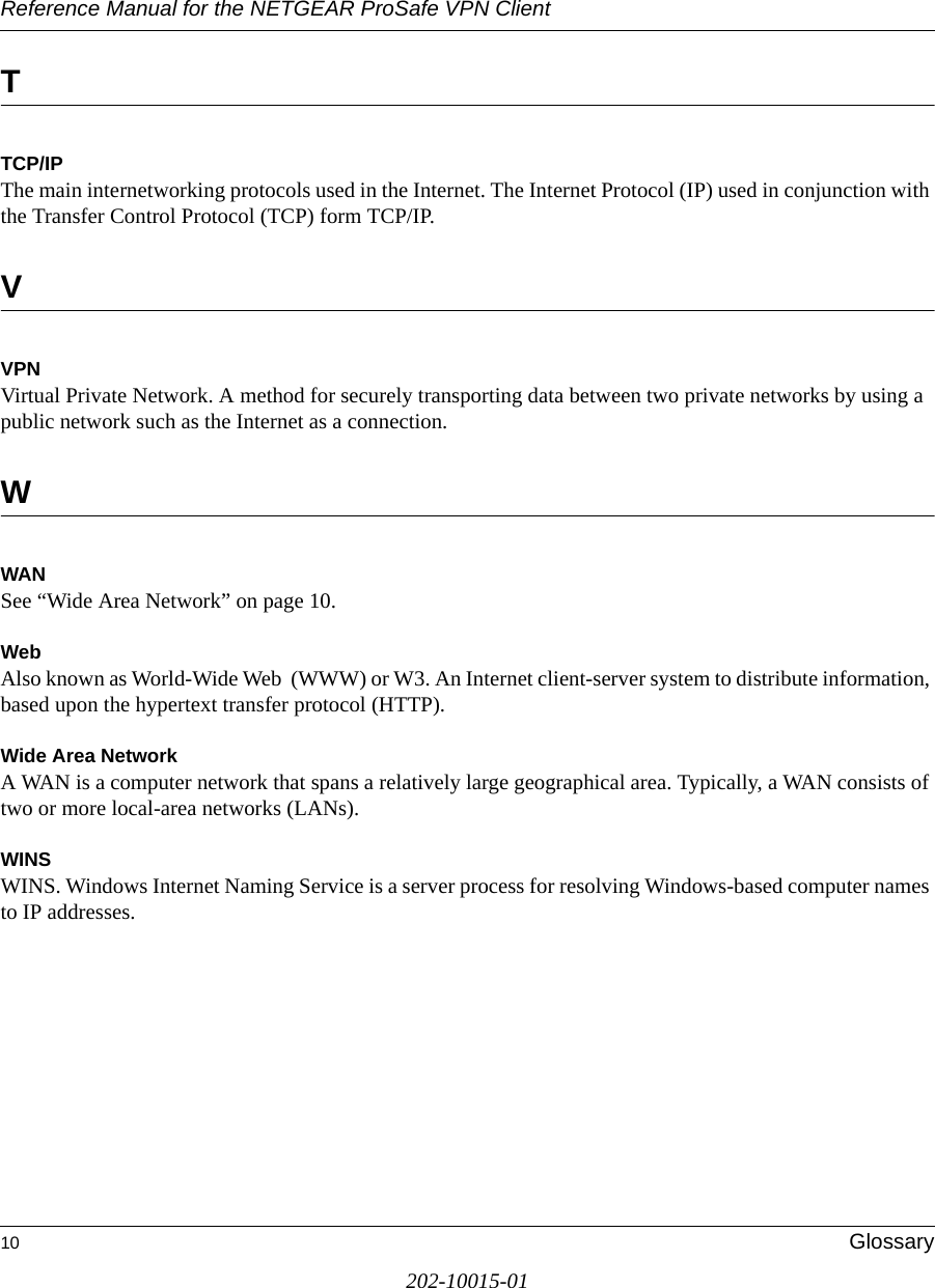
![Reference Manual for the NETGEAR ProSafe VPN ClientVirtual Private Networking B-11202-10015-01VPNC IKE Phase II ParametersThe IKE Phase 2 parameters used in Scenario 1 are: •TripleDES• SHA-1• ESP tunnel mode • MODP group 1 • Perfect forward secrecy for rekeying • SA lifetime of 28800 seconds (one hour)Testing and TroubleshootingOnce you have completed the VPN configuration steps you can use PCs, located behind each of the gateways, to ping various addresses on the LAN-side of the other gateway.You can troubleshoot connections using the VPN status and log details on the Netgear gateway to determine if IKE negotiation is working. Common problems encountered in setting up VPNs include:• Parameters may be configured differently on Gateway A vs. Gateway B.• Two LANs set up with similar or overlapping addressing schemes.• So many required configuration parameters mean errors such as mistyped information or mismatched parameter selections on either side are more likely to happen. Additional Reading•Building and Managing Virtual Private Networks, Dave Kosiur, Wiley & Sons; ISBN: 0471295264•Firewalls and Internet Security: Repelling the Wily Hacker, William R. Cheswick and Steven M. Bellovin, Addison-Wesley; ISBN: 0201633574•VPNs A Beginners Guide, John Mains, McGraw Hill; ISBN: 0072191813• [FF98] Floyd, S., and Fall, K., Promoting the Use of End-to-End Congestion Control in the Internet. IEEE/ACM Transactions on Networking, August 1999.Relevant RFCs listed numerically:](https://usermanual.wiki/Netgear-orporated/05200007/User-Guide-592357-Page-132.png)
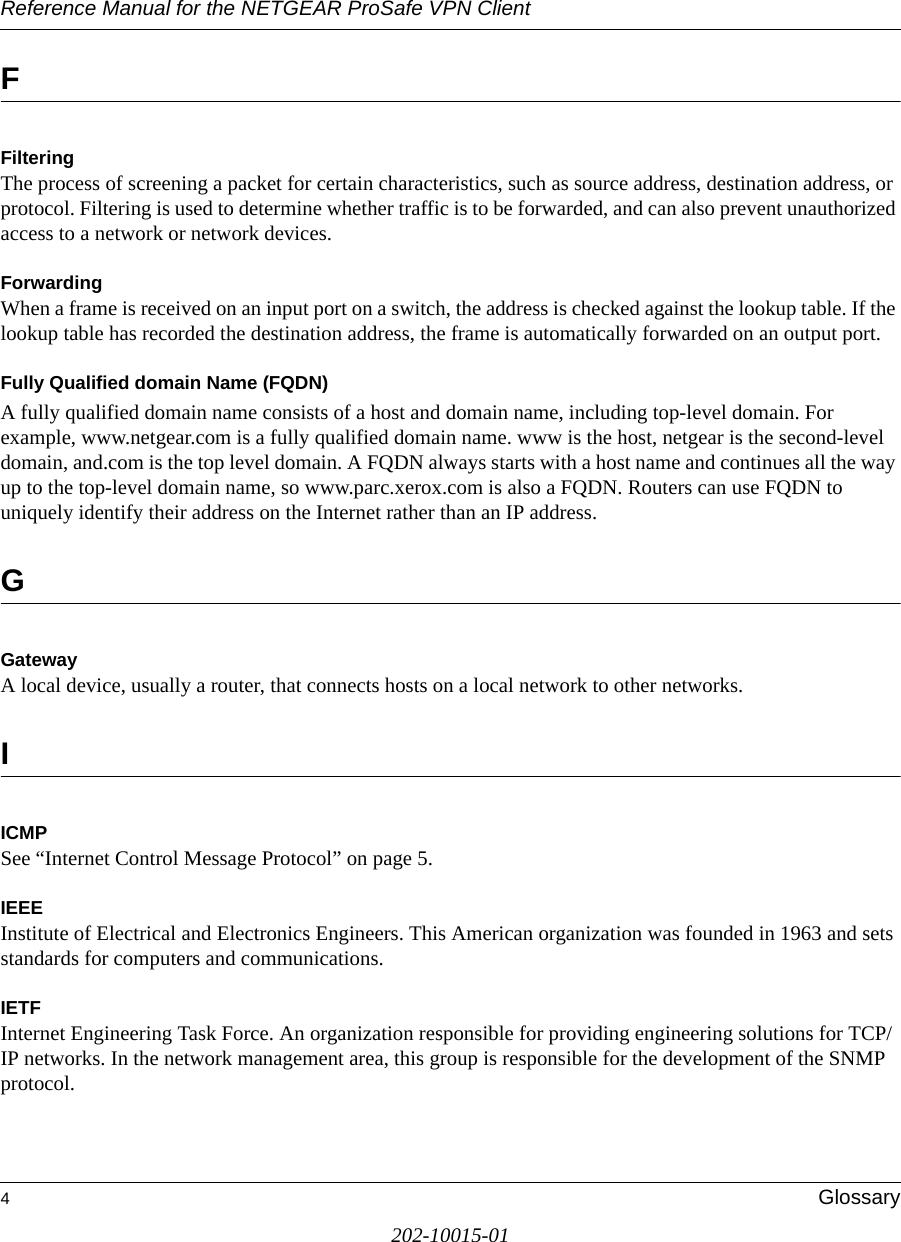
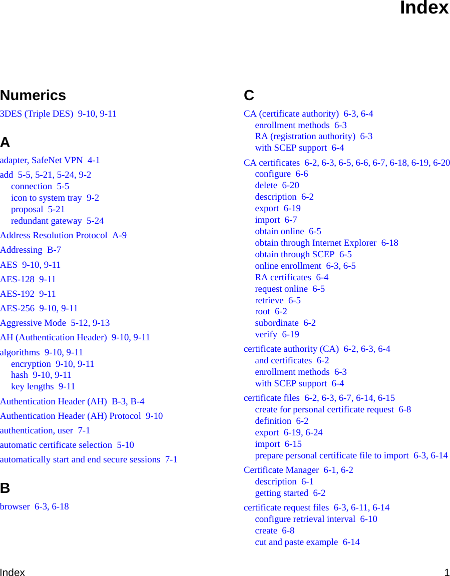
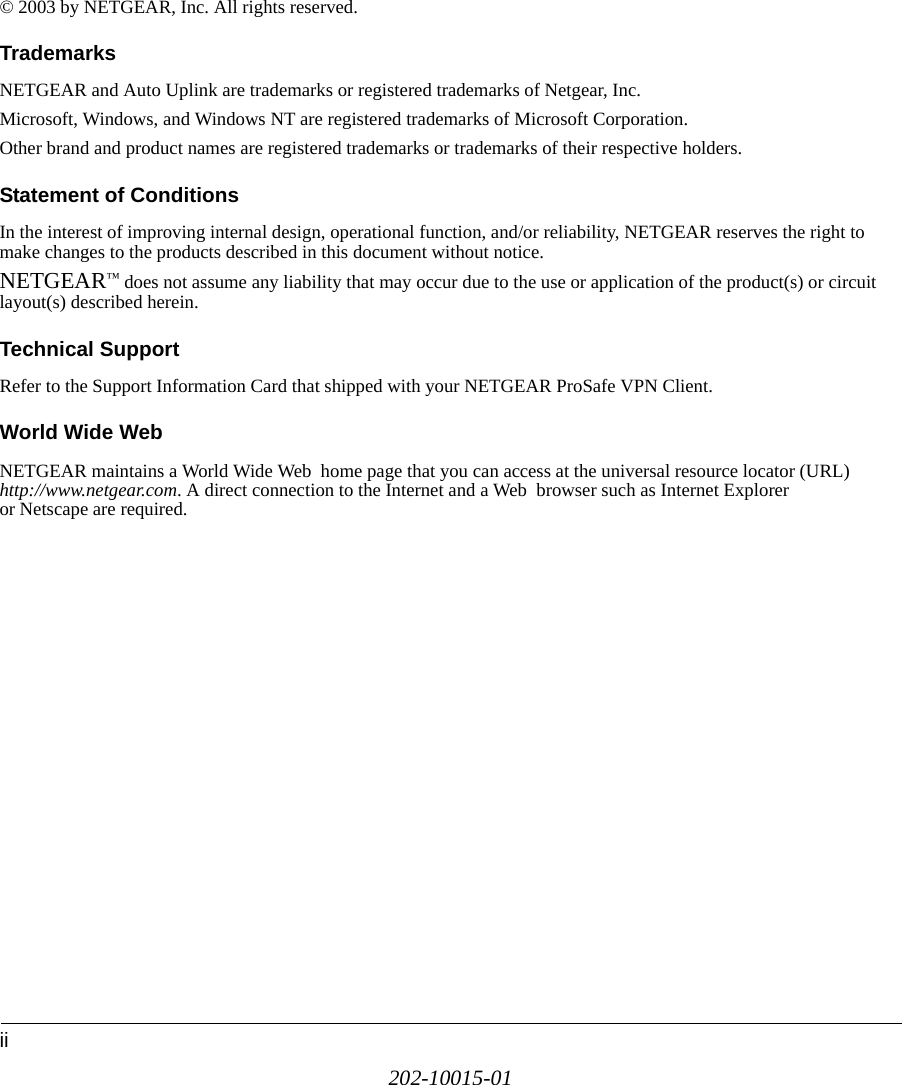
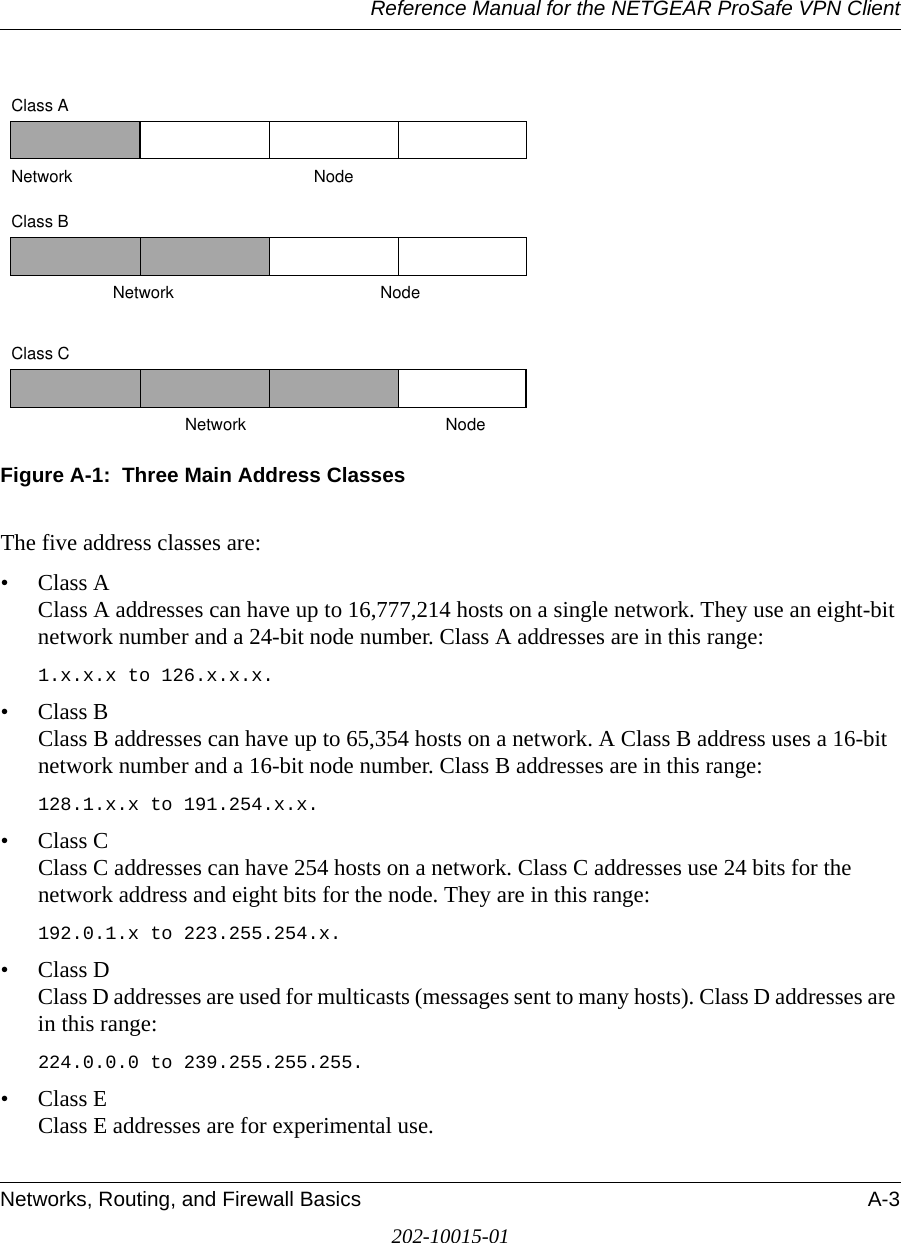
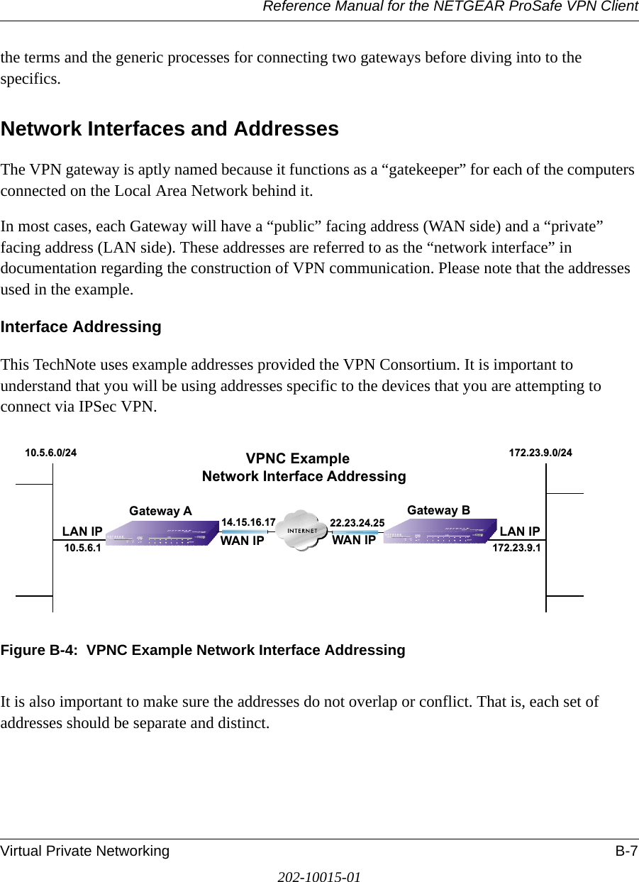
![Reference Manual for the NETGEAR ProSafe VPN ClientB-12 Virtual Private Networking202-10015-01• [RFC 791] Internet Protocol DARPA Internet Program Protocol Specification, Information Sciences Institute, USC, September 1981.• [RFC 1058] Routing Information Protocol, C Hedrick, Rutgers University, June 1988.• [RFC 1483] Multiprotocol Encapsulation over ATM Adaptation Layer 5, Juha Heinanen, Telecom Finland, July 1993.• [RFC 2401] S. Kent, R. Atkinson, Security Architecture for the Internet Protocol, RFC 2401, November 1998.• [RFC 2407] D. Piper, The Internet IP Security Domain of Interpretation for ISAKMP, November 1998.• [RFC 2474] K. Nichols, S. Blake, F. Baker, D. Black, Definition of the Differentiated Services Field (DS Field) in the IPv4 and IPv6 Headers, December 1998.• [RFC 2475] S. Blake, D. Black, M. Carlson, E. Davies, Z. Wang, and W. Weiss, An Architecture for Differentiated Services, December 1998.• [RFC 2481] K. Ramakrishnan, S. Floyd, A Proposal to Add Explicit Congestion Notification (ECN) to IP, January 1999.• [RFC 2408] D. Maughan, M. Schertler, M. Schneider, J. Turner, Internet Security Association and Key Management Protocol (ISAKMP).• [RFC 2409] D. Harkins, D.Carrel, Internet Key Exchange (IKE) protocol.• [RFC 2401] S. Kent, R. Atkinson, Security Architecture for the Internet Protocol.](https://usermanual.wiki/Netgear-orporated/05200007/User-Guide-592357-Page-133.png)
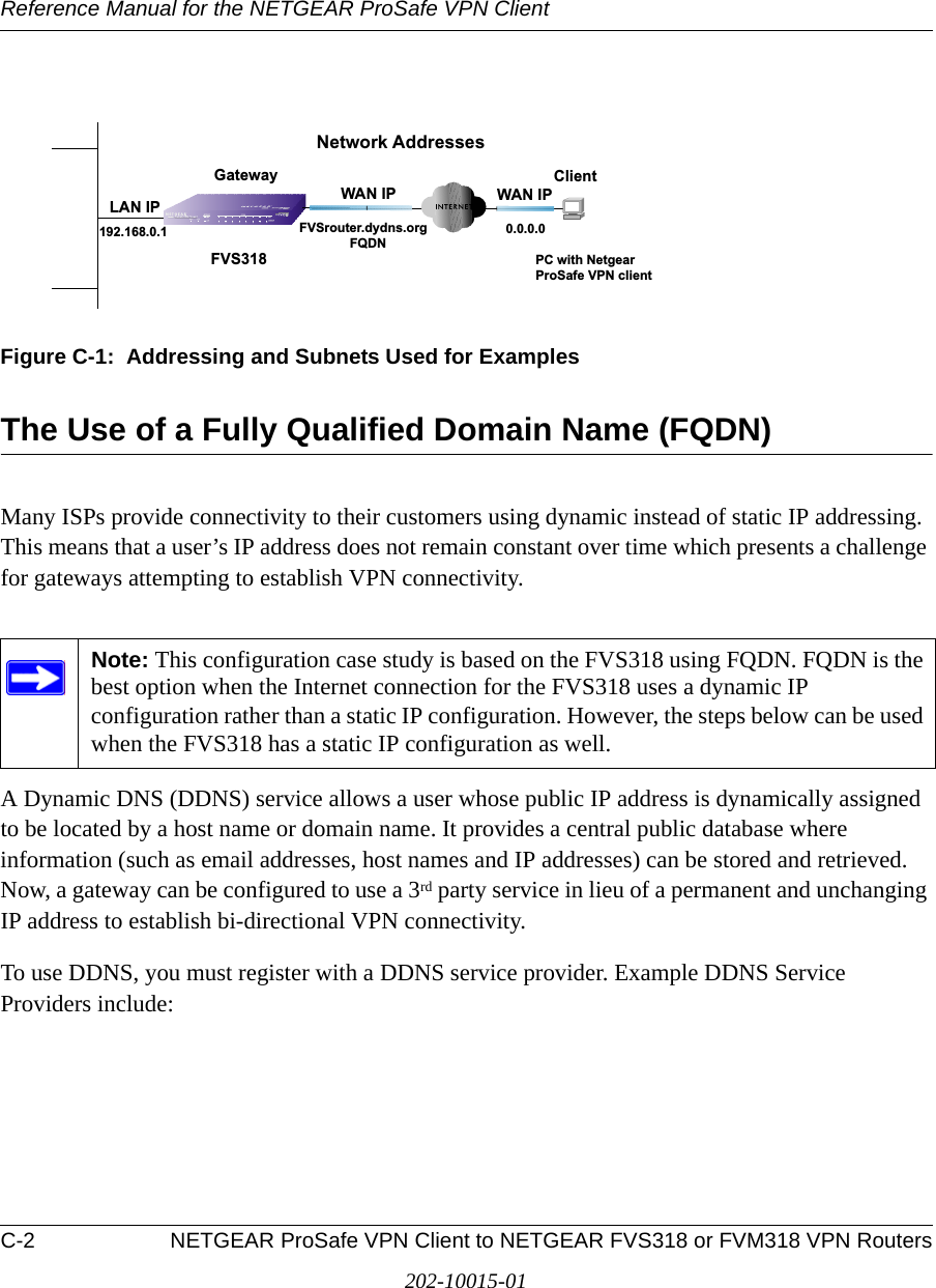
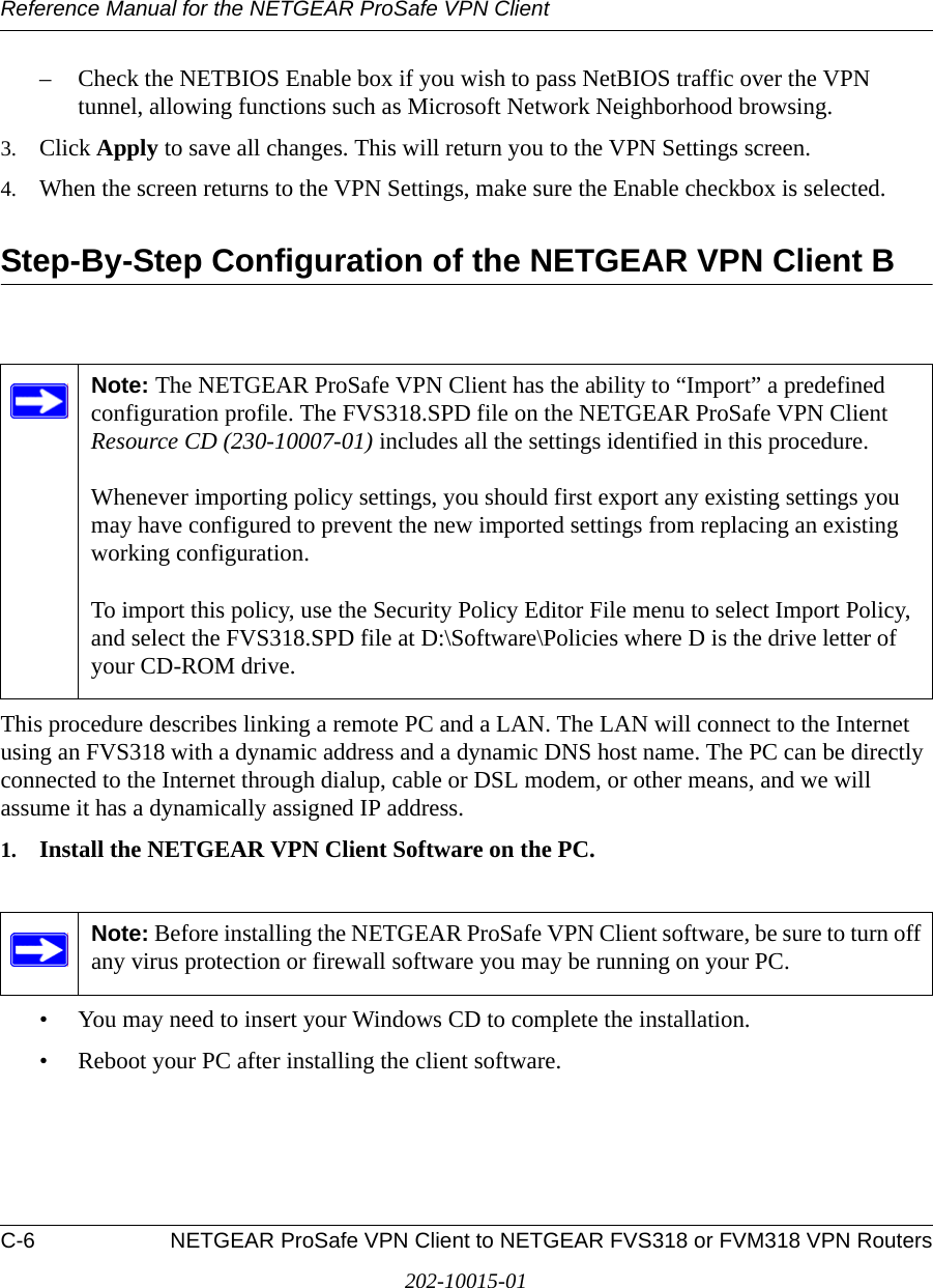
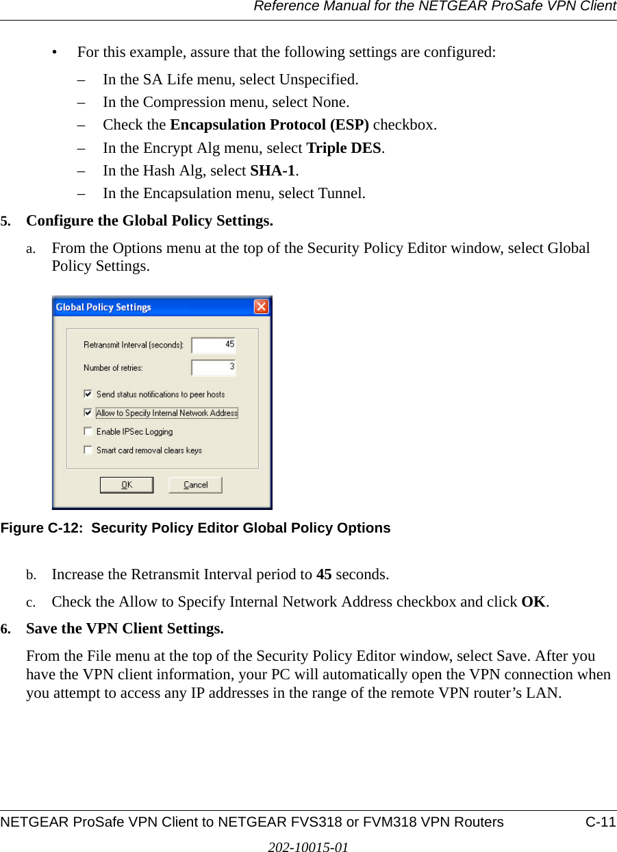
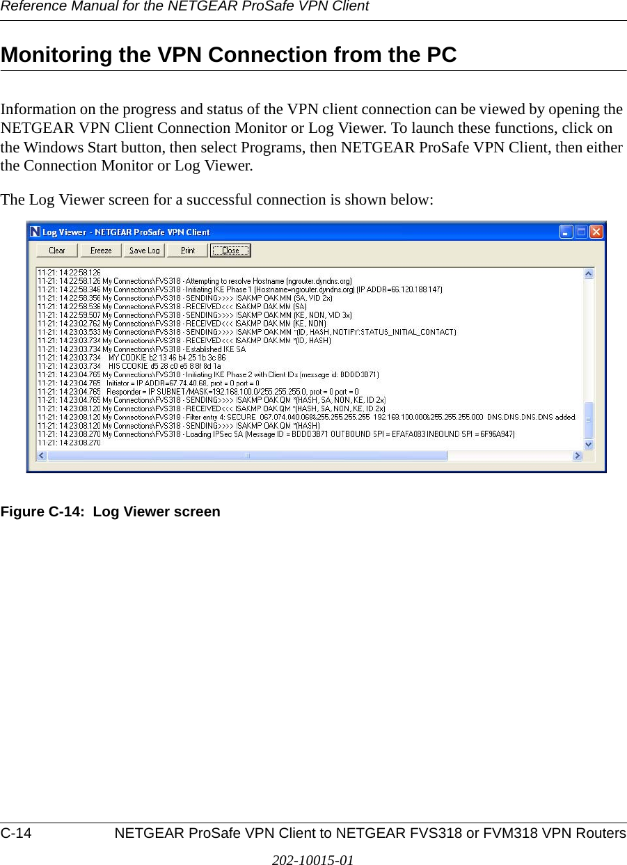
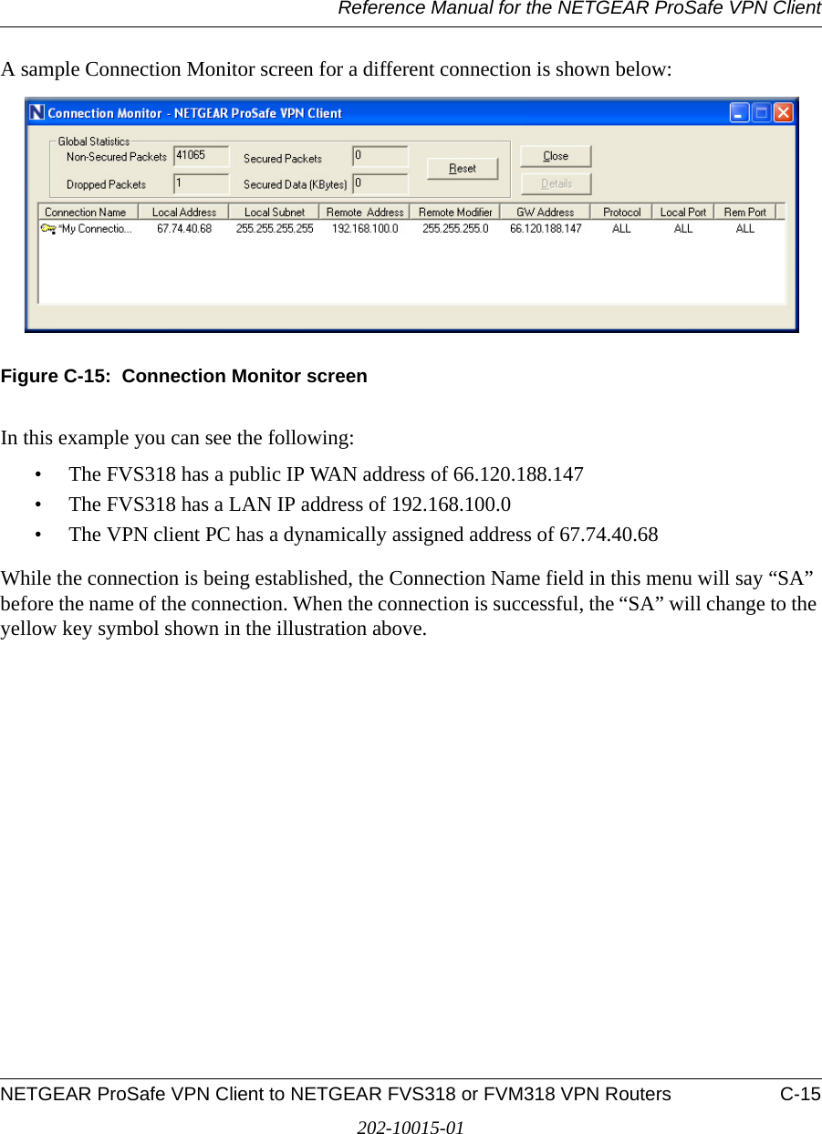
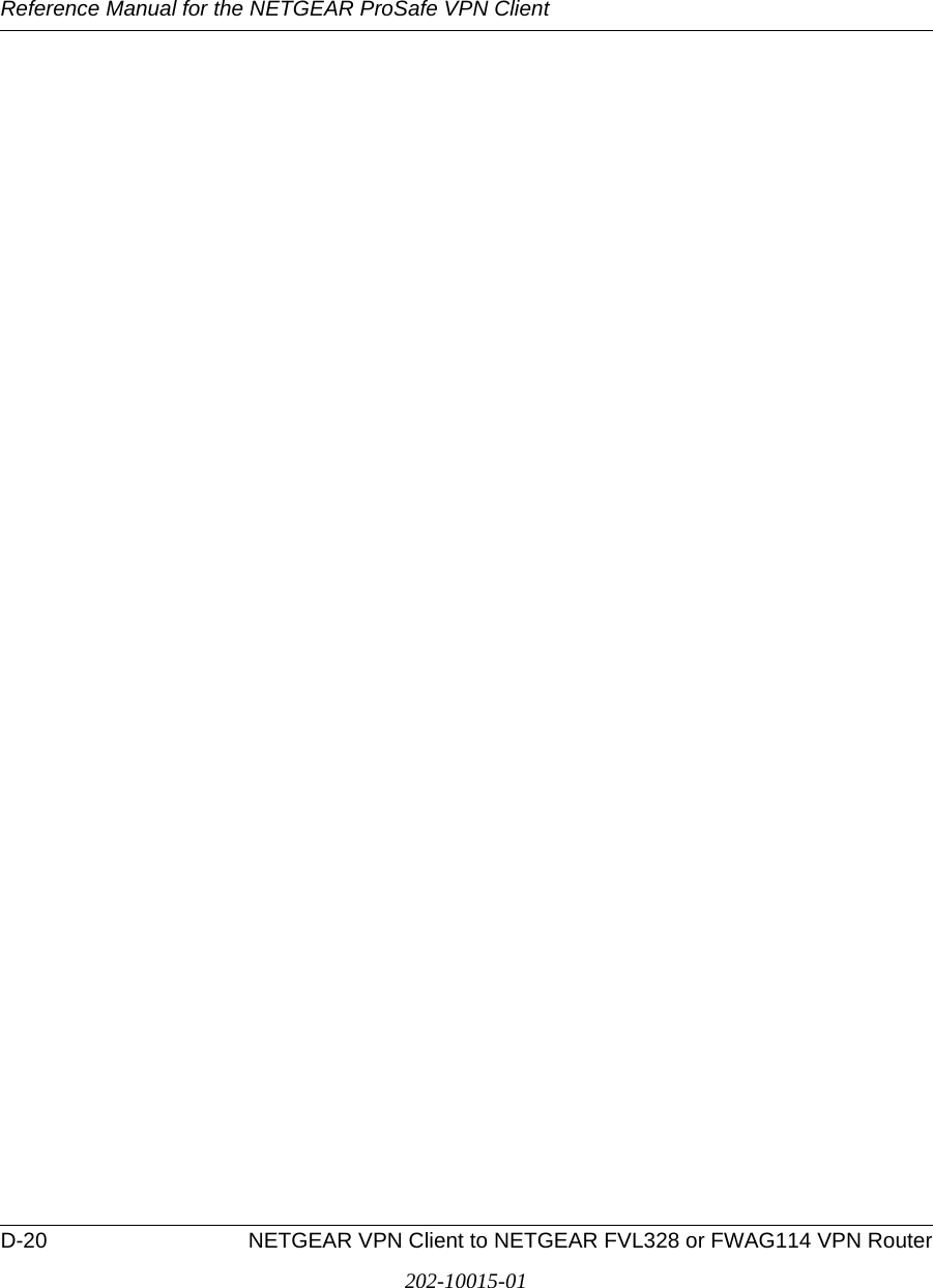
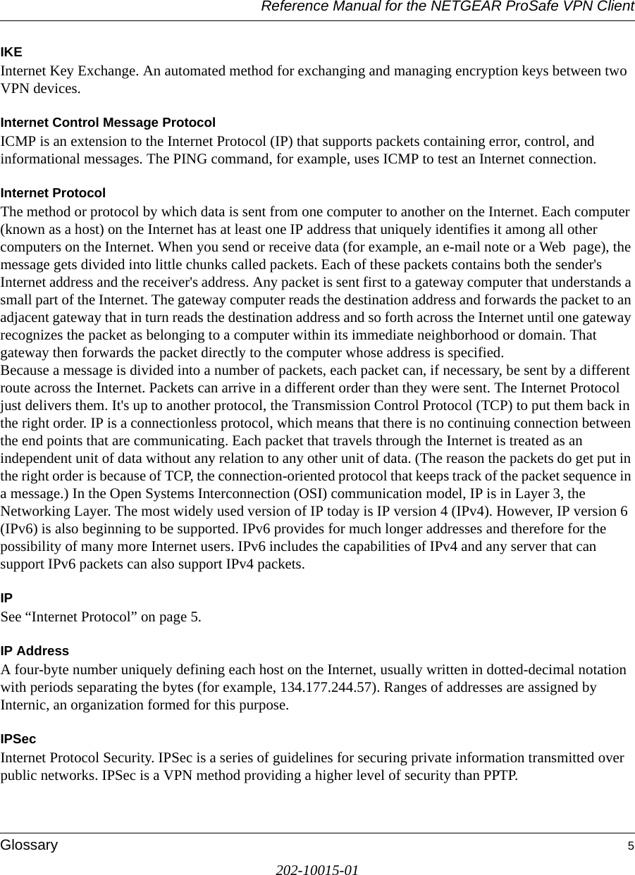
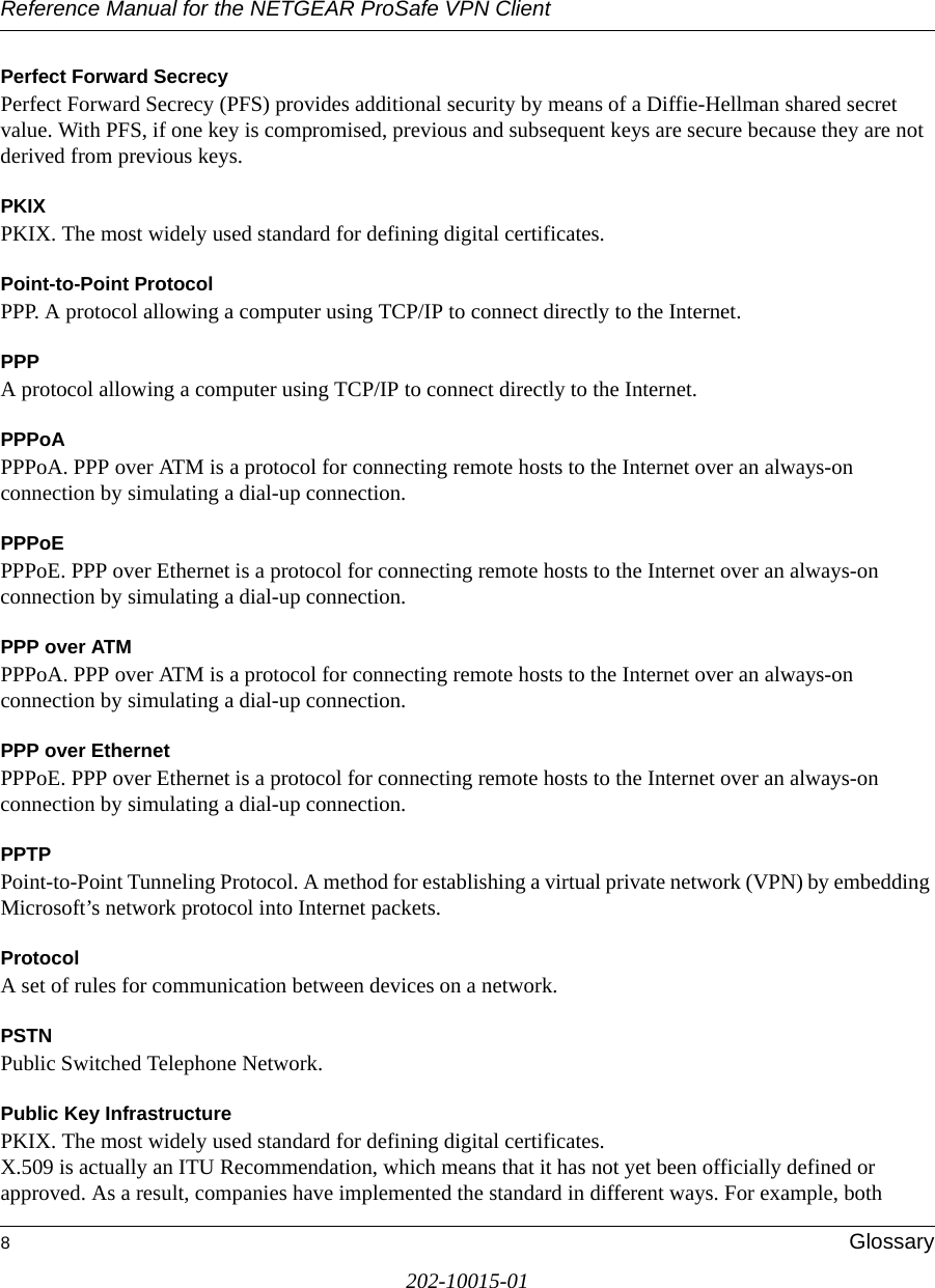
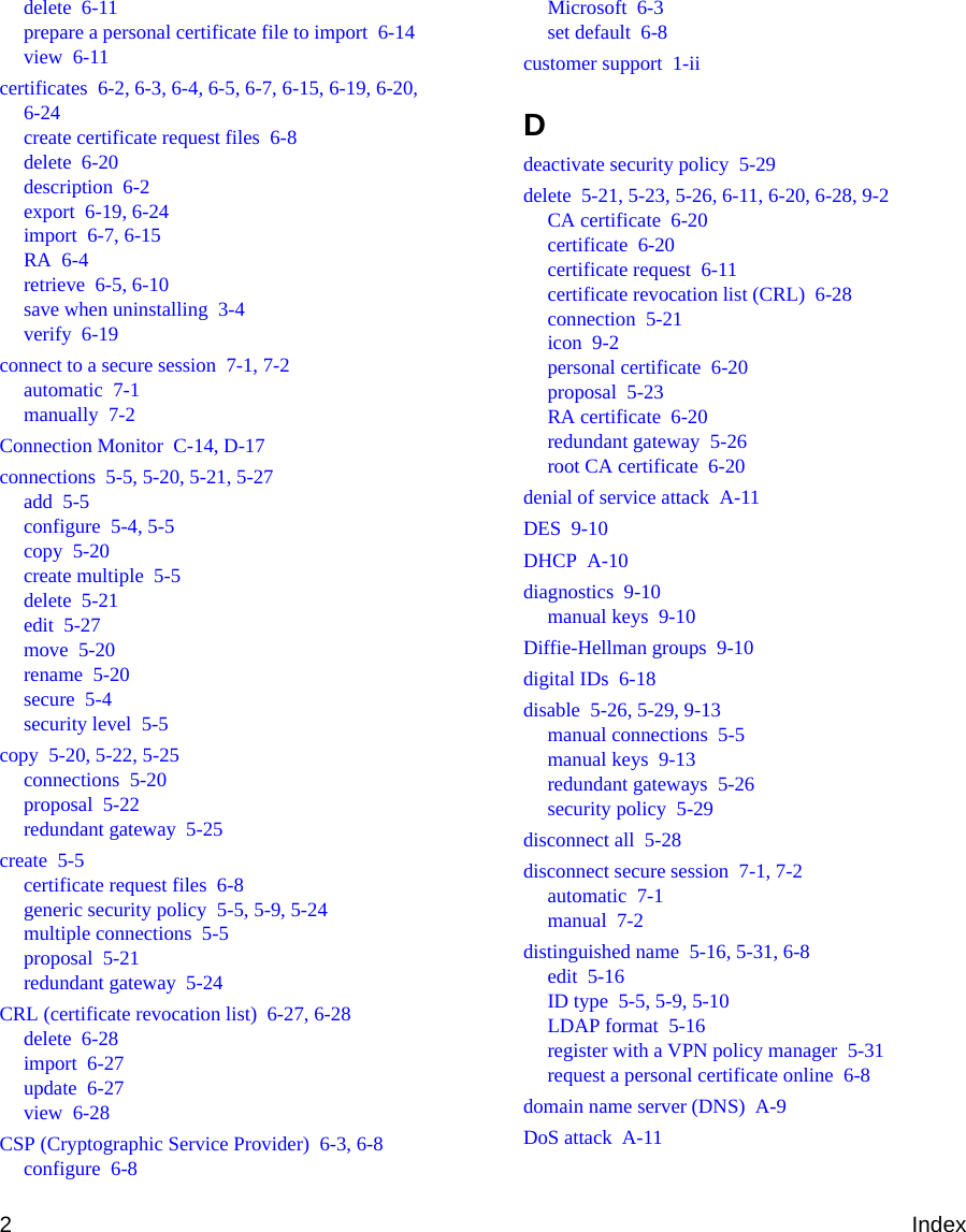
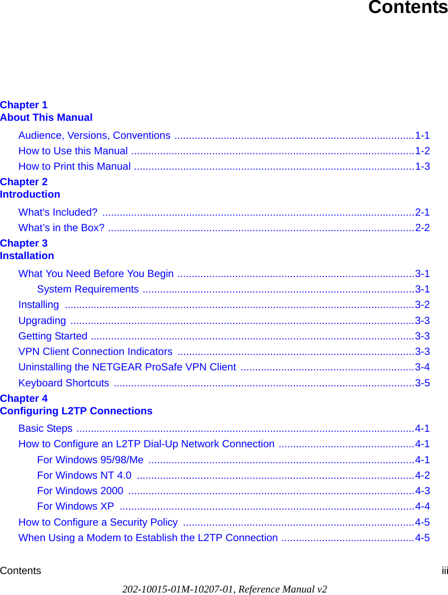
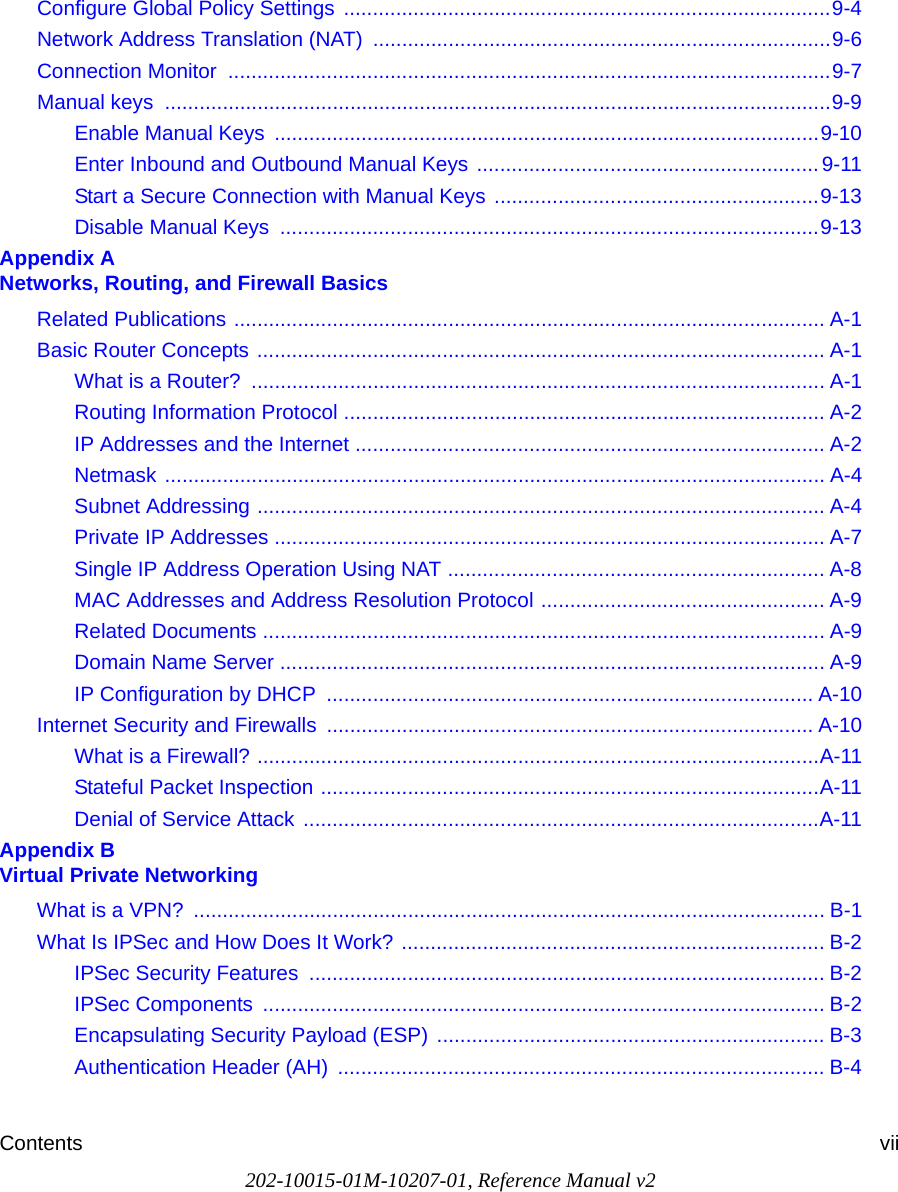
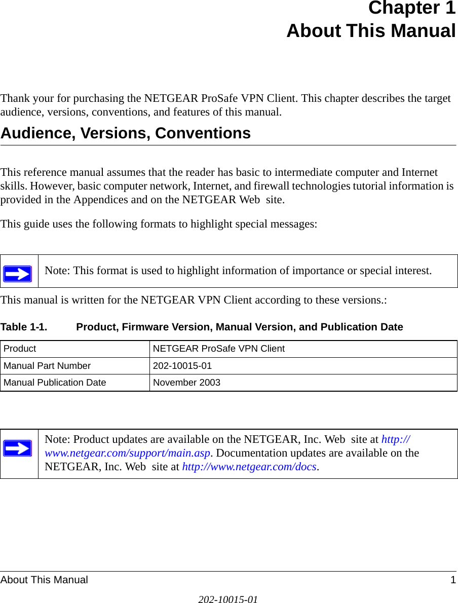
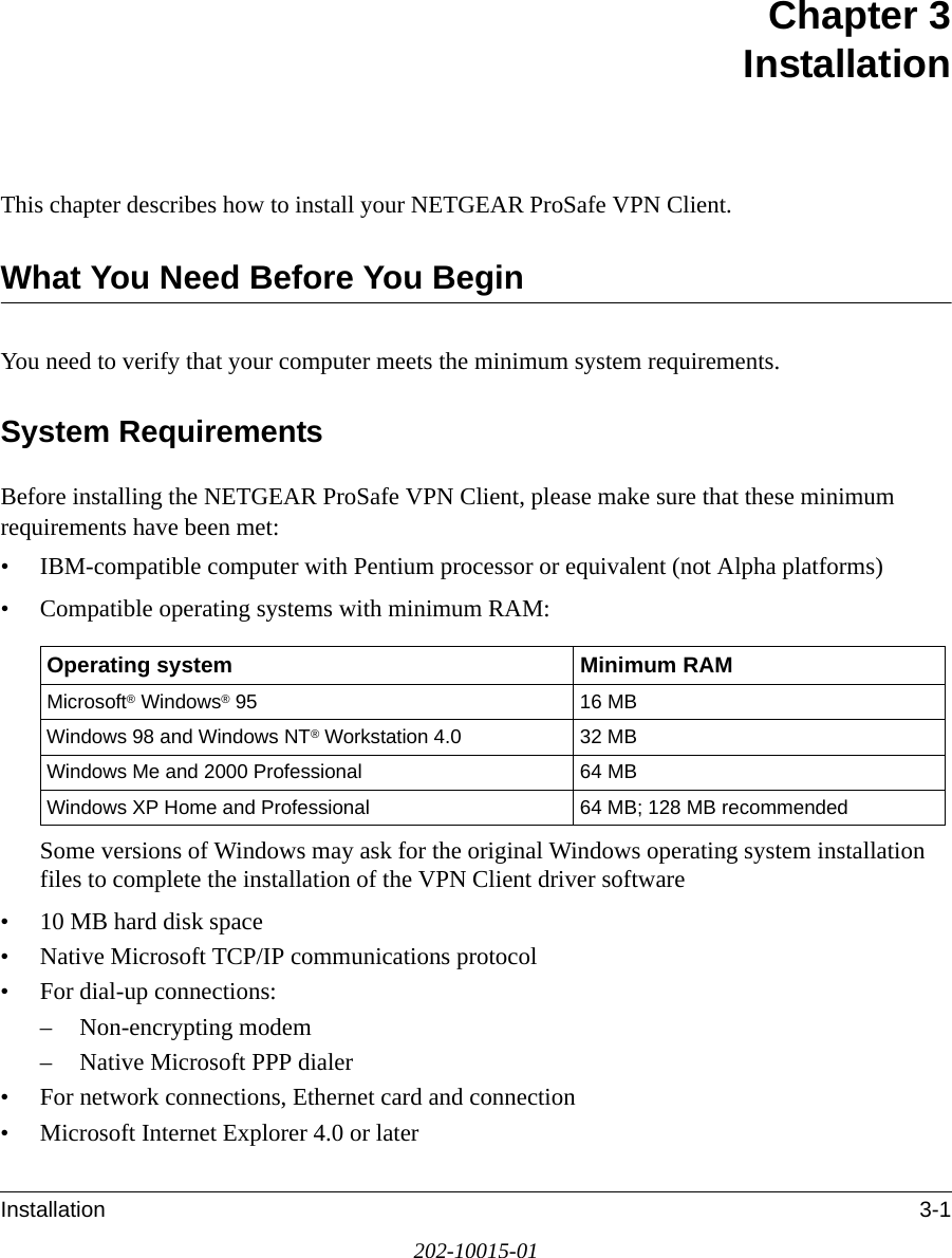
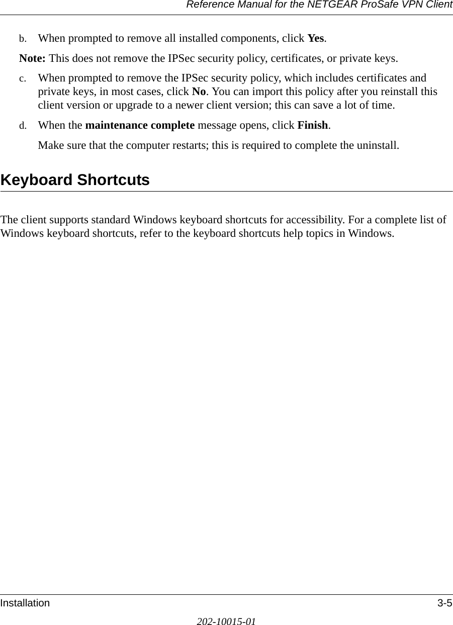
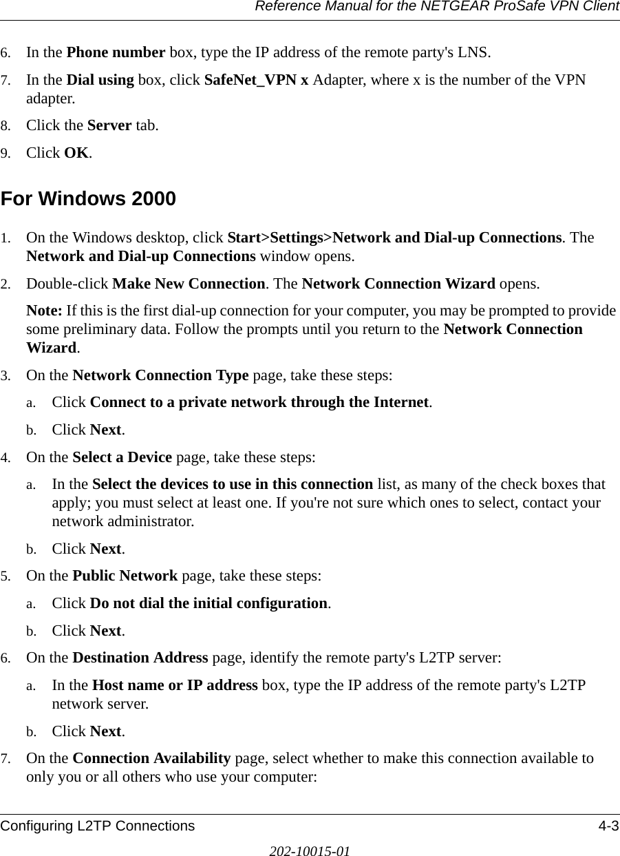
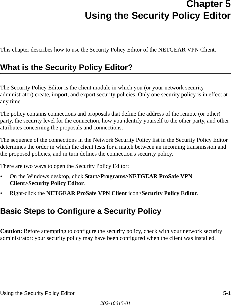
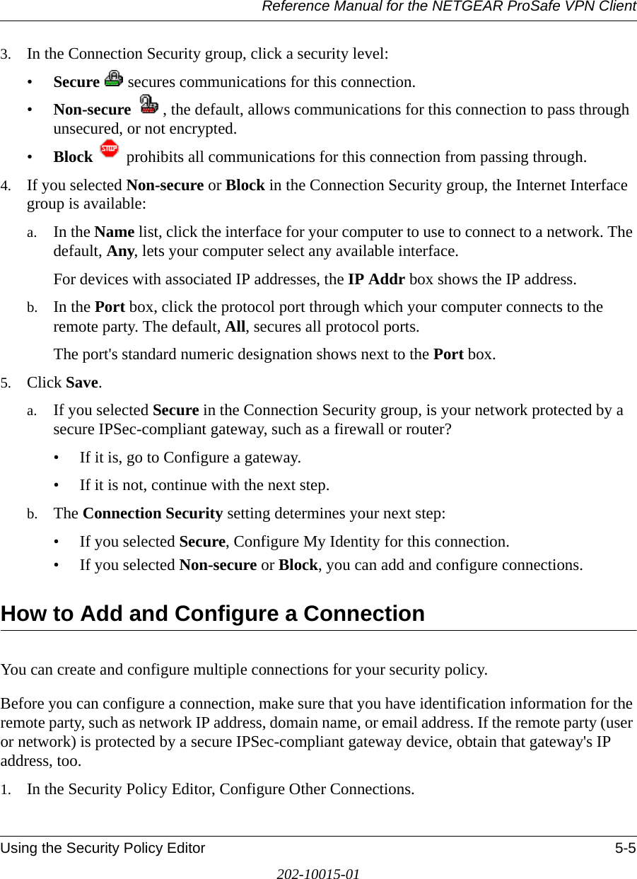
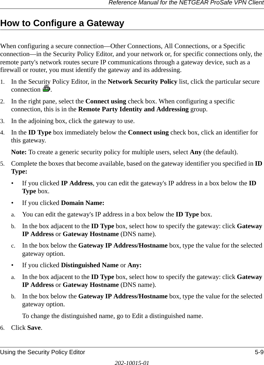
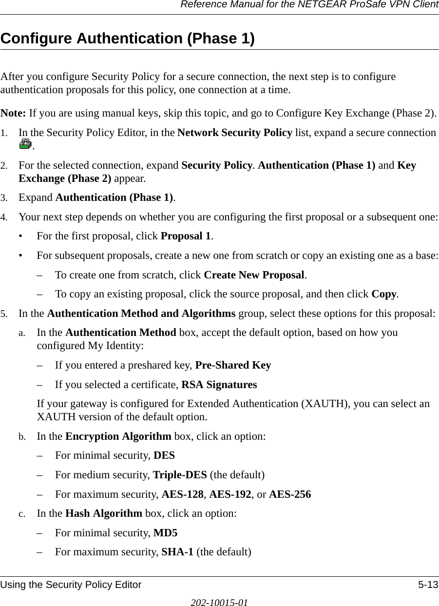
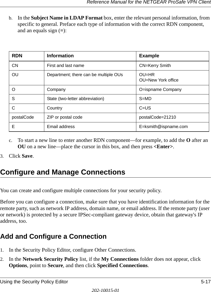
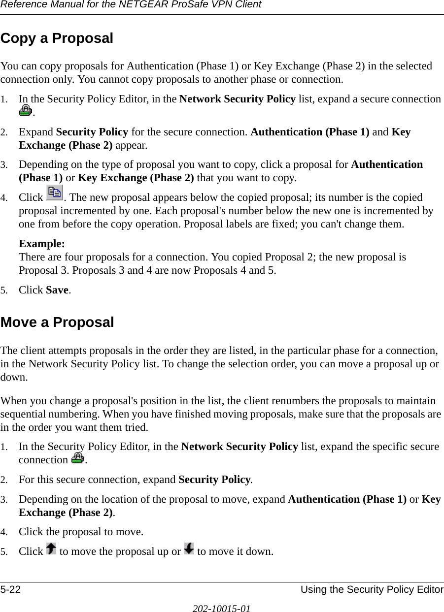
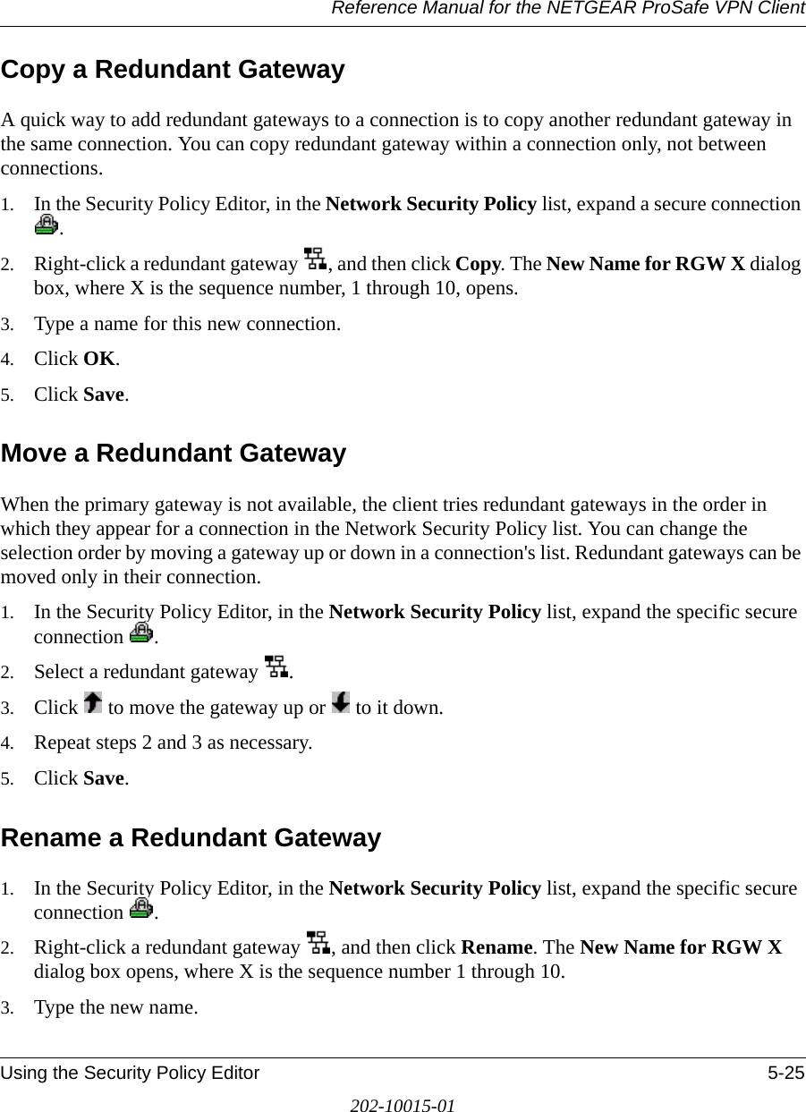
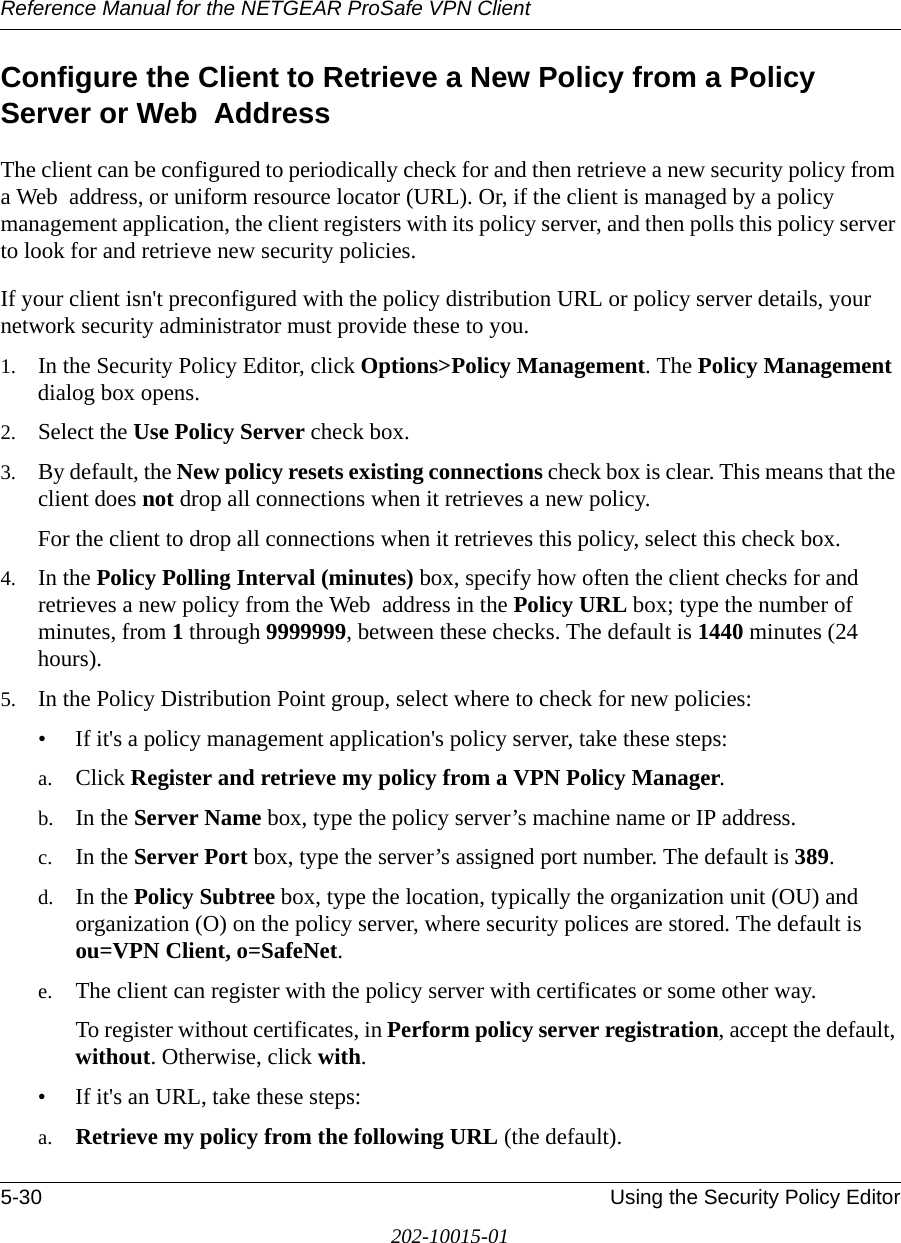
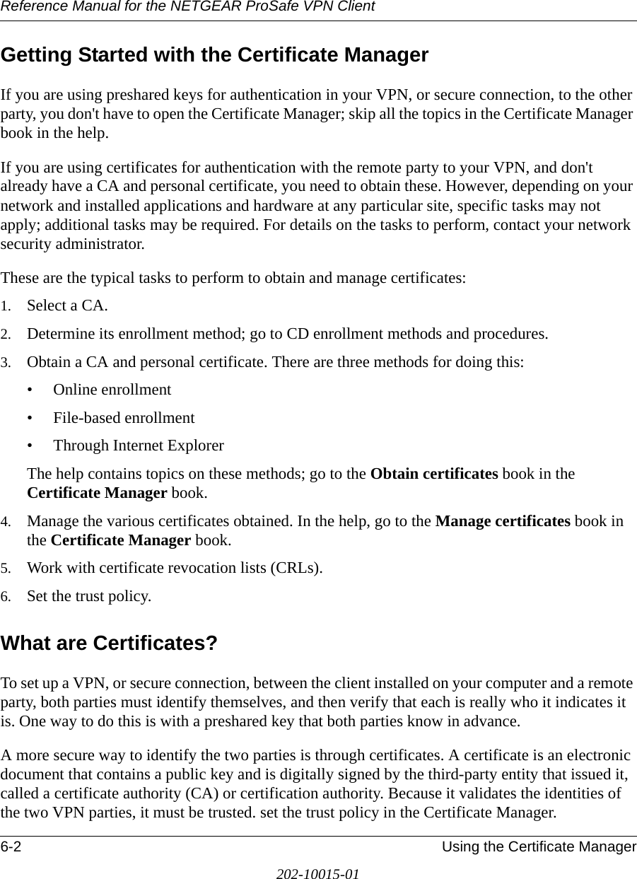
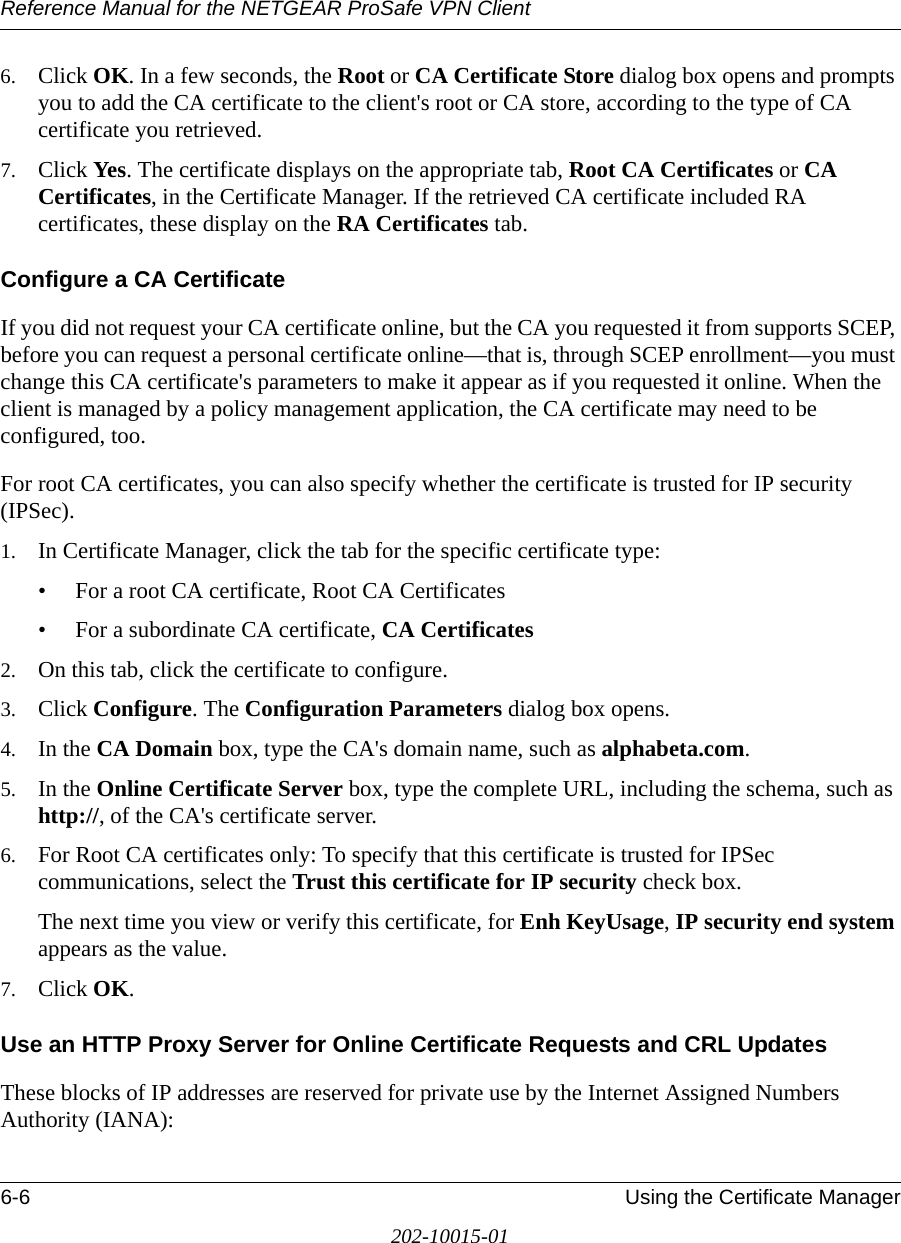
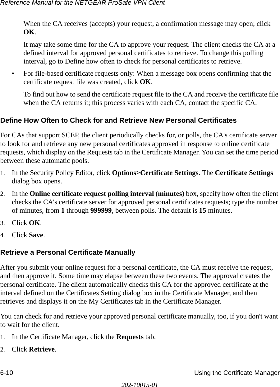
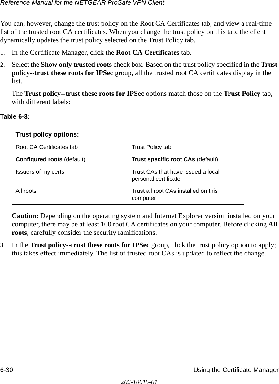
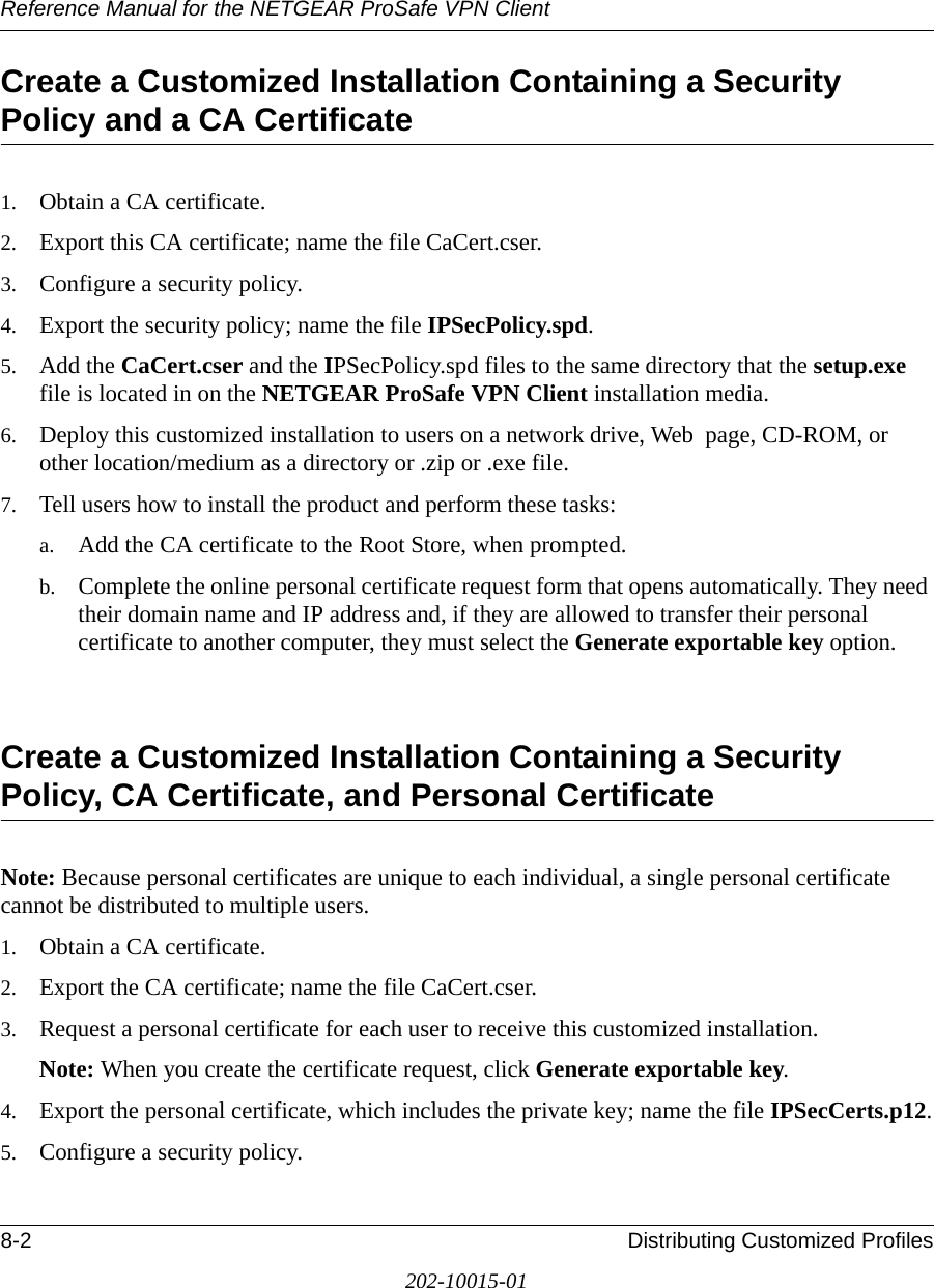
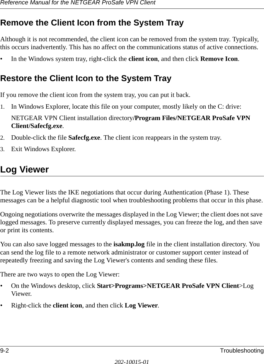
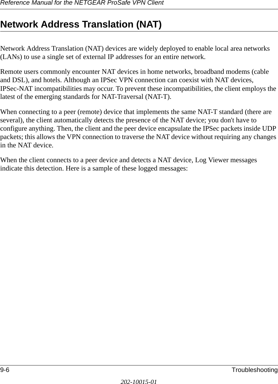
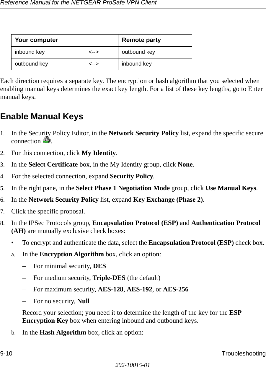
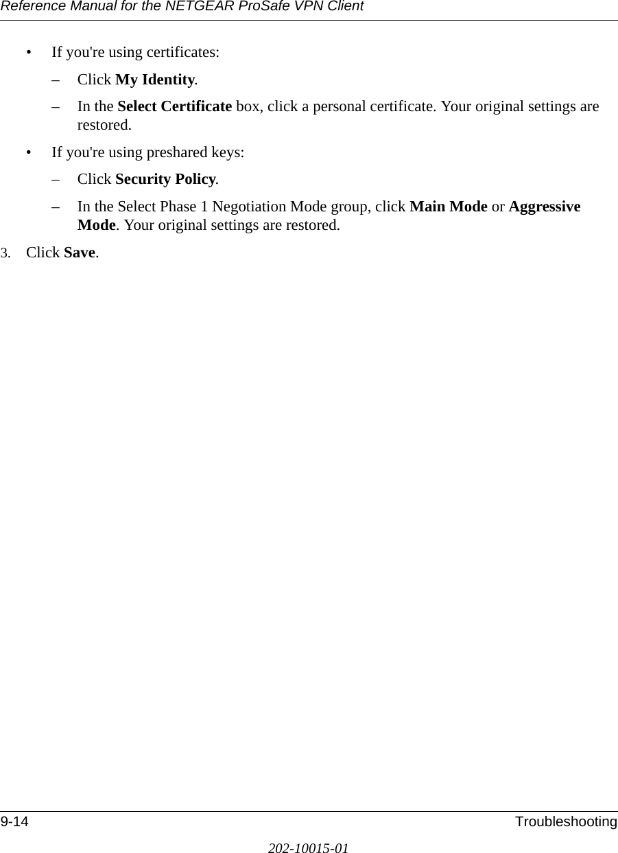
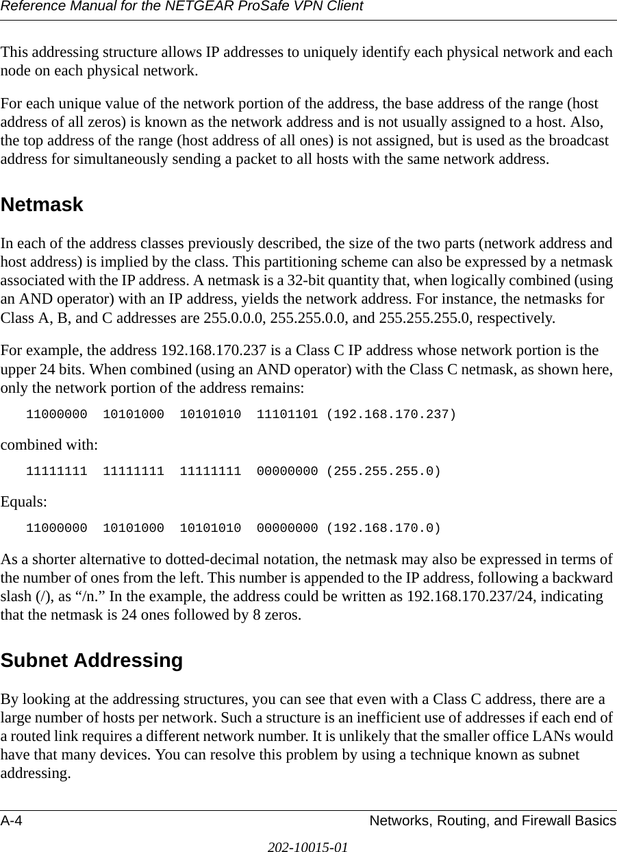
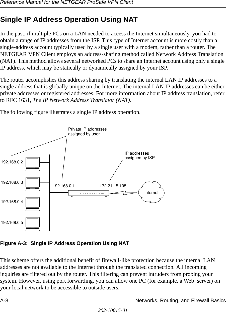
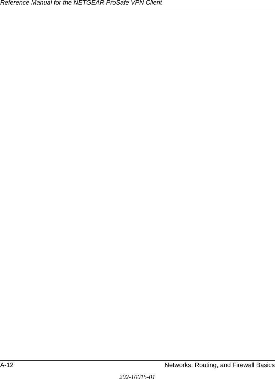
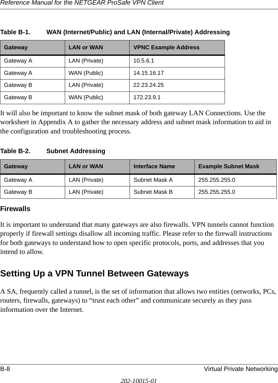
![Reference Manual for the NETGEAR ProSafe VPN ClientC-16 NETGEAR ProSafe VPN Client to NETGEAR FVS318 or FVM318 VPN Routers202-10015-01Monitoring the VPN Connection from the FVS318Information on the status of the VPN client connection can be viewed by opening the FVS318 VPN Status screen. To view this screen, click the Router Status link of the FVS318 main menu, then click the VPN Status button.The FVS318 VPN Status screen for a successful connection is shown below:Figure C-16: FVS318 IPSec Connection Status screenTo view the FVS318 VPN log, click on the Router Status link on the left side of the main menu. Click the Show VPN Logs button. The FVS818 or FVM318 log files should be similar to the example below:Thur, 11/13/2003 10:32:24 - FVS318 IPsec:Receive Packet address:0x13974d4 from 67.74.56.79Thur, 11/13/2003 10:32:24 - FVS318 IPsec:New State index:1, sno:4Thur, 11/13/2003 10:32:24 - FVS318 IPsec:quick_inI1_outR1()Thur, 11/13/2003 10:32:24 - FVS318 IKE:[vpnclient_tmp6] RX << QM_I1 : 67.74.56.79Thur, 11/13/2003 10:32:24 - FVS318 IPsec:in get_ipsec_spi() spi=3834090cThur, 11/13/2003 10:32:24 - FVS318 IKE:[ESP_3DES/AUTH_ALGORITHM_HMAC_SHA1/In SPI:3834090c,Out SPI:97baddc]Thur, 11/13/2003 10:32:24 - FVS318 IPsec:responding to Quick ModeThur, 11/13/2003 10:32:24 - FVS318 IPsec:****Install INBOUND SA:Thur, 11/13/2003 10:32:24 - FVS318 IPsec: ESP(3DES-CBC SHA-1)Thur, 11/13/2003 10:32:24 - FVS318 IKE:[vpnclient_tmp6] TX >> QM_R1 : 67.74.56.79Thur, 11/13/2003 10:32:24 - FVS318 IPsec:inserting event EVENT_RETRANSMIT, timeout in 10 seconds for #4Thur, 11/13/2003 10:32:26 - FVS318 IPsec:Receive Packet address:0x13974d4 from 67.74.56.79Thur, 11/13/2003 10:32:26 - FVS318 IPsec:quick_inI2()Thur, 11/13/2003 10:32:26 - FVS318 IKE:[vpnclient_tmp6] RX << QM_I2 : 67.74.56.79Thur, 11/13/2003 10:32:26 - FVS318 IPsec:****Install OUTBOUNDSA:Thur, 11/13/2003 10:32:26 - FVS318 IPsec: ESP(3DES-CBC SHA-1)Thur, 11/13/2003 10:32:26 - FVS318 IKE:[vpnclient_tmp6] established with 67.74.56.79 successfullyThur, 11/13/2003 10:32:26 - FVS318 IPsec:inserting event EVENT_SA_EXPIRE, timeout in 28980 seconds for #4Thur, 11/13/2003 10:32:26 - FVS318 IPsec:STATE_QUICK_R2: IPsec SA establishedEnd of Log ----------](https://usermanual.wiki/Netgear-orporated/05200007/User-Guide-592357-Page-149.png)