Netgear orporated 06100038 RangeMax NEXT Wireless mPCI User Manual User s Manual
Netgear Incorporated RangeMax NEXT Wireless mPCI User s Manual
Manual

Wireless Lan 802.11n
miniPCI
User’s Manual
Version 1.0
Web Site: www.gemtek.com.tw Phone: +886-3-598-5535
E-Mail: sales@mail.gemtek.com.tw Fax: +886-3-598-5585
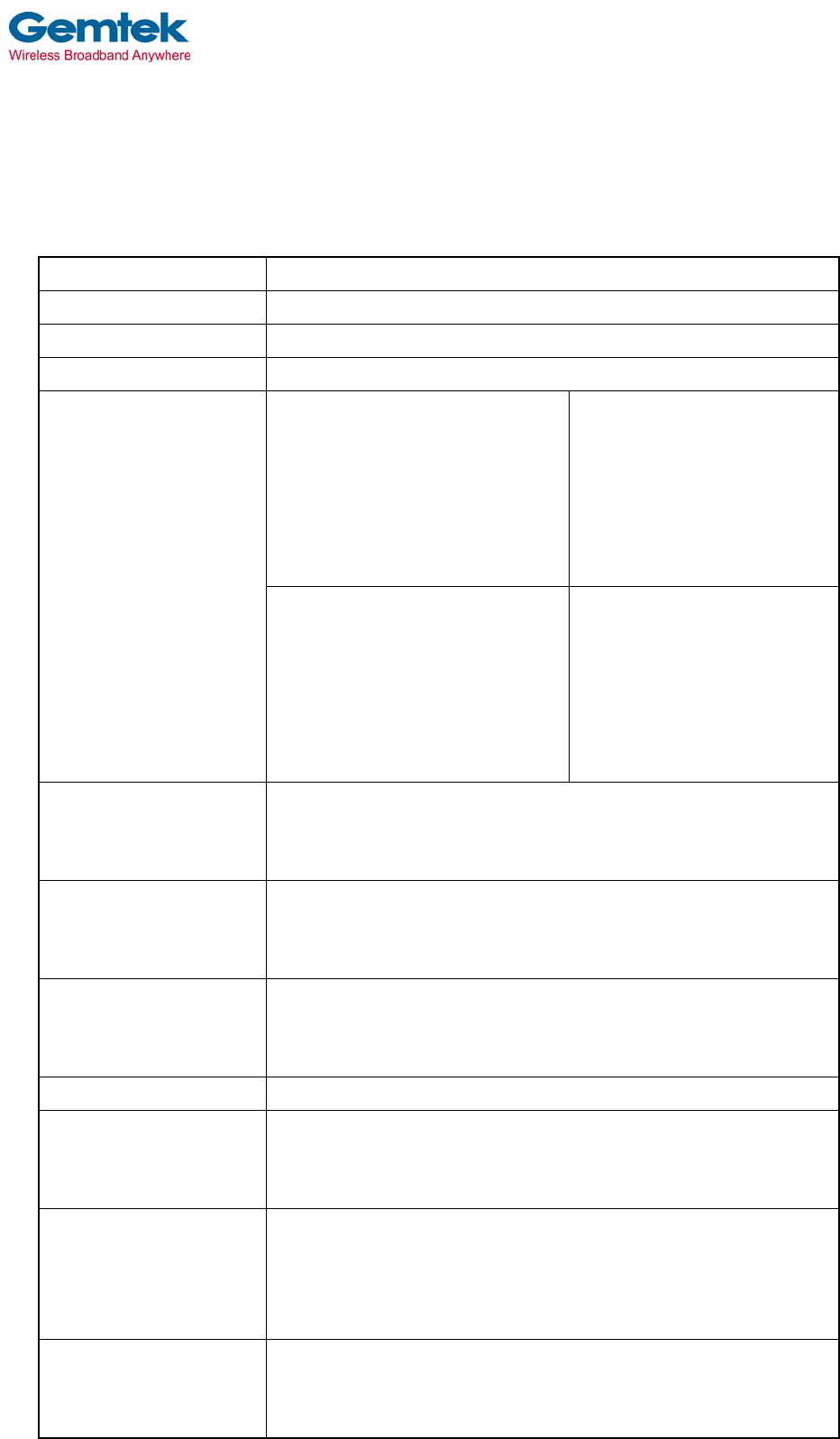
WNR834M IEEE 802.11b/g with EWC
Mini-PCI Wireless LAN Module Specification
Product Name WNR834M
Host Interface miniPCI
Dimensions 59 x 89 x 3.5 mm (non standard size, for module only)
Frequency Band 2.400 ~ 2.4835GHz (subject to local regulations)
USA and Canada:
11ch~
1,2,3,4,5,6,7,8,9,10,11
(EWC 40MHz mode:
1&5,2&6,3&7,4&8,5&9,6&10,7
&11)
Most European countries:
13ch~
1,2,3,4,5,6,7,8,9,10,11,12,13
(EWC 40MHz mode:
1&5,2&6,3&7,4&8,5&9,6&1
0,7&11,8&12,9&13)
Number of Channel France:
4ch~
10,11,12,13
(EWC 40MHz mode: TBD)
Japan:
13ch (optional 14ch)
1,2,3,4,5,6,7,8,9,10,11,12,13
(EWC 40MHz mode:
1&5,2&6,3&7,4&8,5&9,6&1
0,7&11,8&12,9&13)
Modulation
802.11b: CCK, QPSK, BPSK
802.11g: 64-QAM, 16-QAM
EWC: 64-QAM, 16-QAM, QPSK, BPSK
Spreading
802.11b DSSS (Direct Sequence Spread Spectrum)
802.11g OFDM (Orthogonal Frequency Division Multiplexing)
EWC: see Achievable Data-Rate Based on EWC
Data Rate
IEEE 802.11b: 11, 5.5,2,1Mbps
IEEE 802.11g: 54, 48, 36, 24, 18, 12, 9, 6Mbps
EWC: see Achievable Data-Rate Based on EWC
Operating Voltage DC 3.3V +/- 10%
Current consumption
Continuous TX: 570±10mA @ 802.11b, 14dBm Power
Continuous TX: 560±10mA @ 802.11g, 14dBm Power
Continuous TX: 580±10mA @ EWC mode, 14dBm Power
Nominal Temp Range o
f
Transmit Power
802.11b: 18 dBm@1TX; 20 dBm@2TX
802.11g: 17 dBm@1TX; 17 dBm@2TX
EWC: 16 dBm@1TX; 19 dBm@2TX
Tolerance: +/- 1.5dB
Receive Sensitivity in
room temperature
-86dBm @ 802.11b, 11Mbps PER≦8%
-80dBm @ EWC, 6.5Mbps PER≦10%
-71dBm @ EWC, 135Mbps PER≦10%
Web Site: www.gemtek.com.tw Phone: +886-3-598-5535
E-Mail: sales@mail.gemtek.com.tw Fax: +886-3-598-5585
Security TBD- (Hardware 64/128-bit WEP; WEP weak key avoidance;
TKIP; hardware AES engine, WPA, 802.1x and 802.11i)
Driver ?
Standards IEEE 802.11b, 802.11g, EWC, Wi-Fi compliant (TBD)
Warranty 1 year
Temperature Range 0 ~ 65°C (Operating), -20~85°C (Storing)
Humidity Operating Humidity 10% to 85% Non-Condensing
Storage Humidity 5% to 90% Non-Condensing
Antenna No, with 3 RF connectors
Operating Range The transmission speed varies in the surrounding environment.
Roaming Full mobility and seamless roaming from cell to cell and across
access points (subject to access point)
Network Architectures Infrastructure and Ad Hoc
Management Utility Link config for network join and diagnostics
EMC certification TBD(FCC part 15C/15.247; ETS 300 328-2; UL; IEC60950; EN301 489-1,
17; prEN50371; CE Mark; TELEC.)
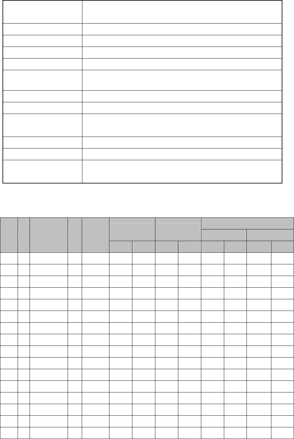
Achievable Data-Rate Based on EWC
Datarate(Mbps)
NCBPS NDBPS
800nsGI 400nsGI
MCS
Index Nss Modulation R NBPSC
20MHz 40MHz 20MHz 40MHz 20MHz 40MHz 20MHz 40MHz
0 1 BPSK ½ 1 52 108 26 54 6.5 13.5 7.200 15
1 1 QPSK ½ 2 104 216 52 108 13.0 27.0 14.400 30
2 1 QPSK ¾ 2 104 216 78 162 19.5 40.5 21.700 45
3 1 16-QAM ½ 4 208 432 104 216 26.0 54.0 28.900 60
4 1 16-QAM ¾ 4 208 432 156 324 39.0 81.0 43.300 90
5 1 64-QAM 2/3 6 312 648 208 432 52.0 108.0 57.800 120
6 1 64-QAM ¾ 6 312 648 234 486 58.5 121.5 65.000 135
7 1 64-QAM 5/6 6 312 648 260 540 65.0 135.0 72.200 150
8 2 BPSK ½ 1 104 216 52 108 13.0 27.0 14.444 30
9 2 QPSK ½ 2 208 432 104 216 26.0 54.0 28.889 60
10 2 QPSK ¾ 2 208 432 156 324 39.0 81.0 43.333 90
11 2 16-QAM ½ 4 416 864 208 432 52.0 108.0 57.778 120
12 2 16-QAM 3/4 4 416 864 312 648 78.0 162.0 86.667 180
13 2 64-QAM 2/3 6 624 1296 416 864 104.0 216.0 115.556 240
14 2 64-QAM ¾ 6 624 1296 468 972 117.0 243.0 130.000 270
15 2 64-QAM 5/6 6 624 1296 520 1080 130.0 270.0 144.444 300
5
5
4
4
3
3
2
2
1
1
DD
CC
BB
AA
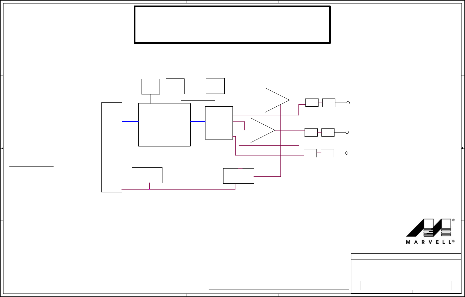
Block Diagram
Table of Contents:
3. JTAG, SPI EEPROM, and Power Supply
2. MiniPCI connector
1. Title Page
4. 88W8361P SoC Interface
6. 88W8060 F I/O
Γ
7. 802.11g/b External Power Amplifier and RF I/O
PROPRIETARY INFORMATION
MARVELL SEMICONDUCTOR
NOTE: THIS SCHEMATIC IS AN ADVANCED DESIGN.
MARVELL RESERVES THE RIGHT TO MAKE CHANGES
TO THE SCHEMATIC AT ANY TIME WITHOUT NOTICE.
WLAN 802.11g/b 2x3 MIMO
Reference Design Schematic
MB-82 v1.0
5. Memory DRAM/Flash
Γ
MV-SR00101-01
WMIM-205GN
Design Schematic v1.1
88W8361P
88W8060
Power Supplies
Antenna Connect B
Antenna Connect A
WLAN 802.11g/b Wireless
XTAL
40 MHz
Antenna Connect C
EEPROM
Filter
Filter
Filter
Switch
Switch
Switch
2.4 GHz PA
2.4 GHz PA
Interface
CardBUS
miniPCI
PCI
Power Supplie
U2 U1
3.3V
1.2V
3.0V
U4 U5
U7
U9
U6
U8
U11
BP1
BP2
BP3
Y1
U3
SDRAM
U13
-
MB-82 v 1.0 Reference Schematic
B
1 7Thursday, May 04, 2006
Marvell Semiconductor Inc.
5488 Marvell Lane
Santa Clara, CA 95054, USA
Title
Size Document Number Rev
Date: Sheet of
Company
MARVELL SEMICONDUCTOR CONFIDENTIAL
Model name: WNR834M for NETGEAR
IC statement
Operation is subject to the following two conditions:
1) This device may not cause interference and
2) This device must accept any interference, including interference that may
cause undesired operation of the device.
IMPORTANT NOTE:
IC Radiation Exposure Statement:
This equipment complies with IC radiation exposure limits set forth for an
uncontrolled environment. End users must follow the specific operating
instructions for satisfying RF exposure compliance. This equipment should be
installed and operated with minimum distance 20cm between the radiator &
your body.
This transmitter must not be co-located or operating in conjunction with any
other antenna or transmitter.
Federal Communication Commission Interference Statement
This equipment has been tested and found to comply with the limits for a Class
B digital device, pursuant to Part 15 of the FCC Rules. These limits are
designed to provide reasonable protection against harmful interference in a
residential installation. This equipment generates, uses and can radiate radio
frequency energy and, if not installed and used in accordance with the
instructions, may cause harmful interference to radio communications.
However, there is no guarantee that interference will not occur in a particular
installation. If this equipment does cause harmful interference to radio or
television reception, which can be determined by turning the equipment off and
on, the user is encouraged to try to correct the interference by one of the
following measures:
- Reorient or relocate the receiving antenna.
- Increase the separation between the equipment and receiver.
- Connect the equipment into an outlet on a circuit different from that
to which the receiver is connected.
- Consult the dealer or an experienced radio/TV technician for help.
This device complies with Part 15 of the FCC Rules. Operation is subject to the
following two conditions: (1) This device may not cause harmful interference,
and (2) this device must accept any interference received, including
interference that may cause undesired operation.
FCC Caution: Any changes or modifications not expressly approved by the
party responsible for compliance could void the user's authority to operate this
equipment.
IMPORTANT NOTE:
FCC Radiation Exposure Statement:
This equipment complies with FCC radiation exposure limits set forth for an
uncontrolled environment. This equipment should be installed and operated with
minimum distance 20cm between the radiator & your body.
This transmitter must not be co-located or operating in conjunction with any other
antenna or transmitter.
NETGEAR declares that WNR834M (FCC ID: PY306100038) is limited in
CH1~CH11 for 2.4 GHz by specified firmware controlled in U.S.A.

This device is intended only for OEM integrators under the following
conditions:
1) The antenna must be installed such that 20 cm is maintained between the
antenna and users, and
2) The transmitter module may not be co-located with any other transmitter or
antenna.
As long as 2 conditions above are met, further transmitter test will not be required.
However, the OEM integrator is still responsible for testing their end-product for any
additional compliance requirements required with this module installed (for example,
digital device emissions, PC peripheral requirements, etc.).
IMPORTANT NOTE: In the event that these conditions can not be met (for example
certain laptop configurations or co-location with another transmitter), then the FCC
authorization is no longer considered valid and the FCC ID can not be used on the
final product. In these circumstances, the OEM integrator will be responsible for
re-evaluating the end product (including the transmitter) and obtaining a separate
FCC authorization.
End Product Labeling
This transmitter module is authorized only for use in device where the antenna may
be installed such that 20 cm may be maintained between the antenna and users (for
example: Access point, Router…etc). The final end product must be labeled in a
visible area with the following: “Contains TX FCC ID: PY306100038”.
Manual Information That Must be Included
The OEM integrator has to be aware not to provide information to the end user
regarding how to install or remove this RF module in the users manual of the end
product which integrate this module.
The users manual for OEM integrators must include the following information in a
prominent location “ IMPORTANT NOTE: To comply with FCC RF exposure
compliance requirements, the antenna used for this transmitter must be installed to
provide a separation distance of at least 20 cm from all persons and must not be
co-located or operating in conjunction with any other antenna or transmitter.