Netgear orporated 07200066 Prosafe Wireless ADSL Modem VPN Firewall Router User Manual DGFV114G IG
Netgear Incorporated Prosafe Wireless ADSL Modem VPN Firewall Router DGFV114G IG
Manual
)NSTALLATION'UIDE
DGFV114G ProSafe™ Wireless ADSL Modem VPN Firewall Router
Start Here
Follow these instructions to set up your wireless ADSL gateway. You can also
consult the documentation links on the Resource CD or the NETGEAR knowledge Base at
http://kbserver.netgear.com.
Prepare to Install Your Gateway
The DGFV114G ProSafe Wireless ADSL Modem VPN Firewall Router is connected via
an ADSL connection using the internal modem.
First, Connect the DGFV114G
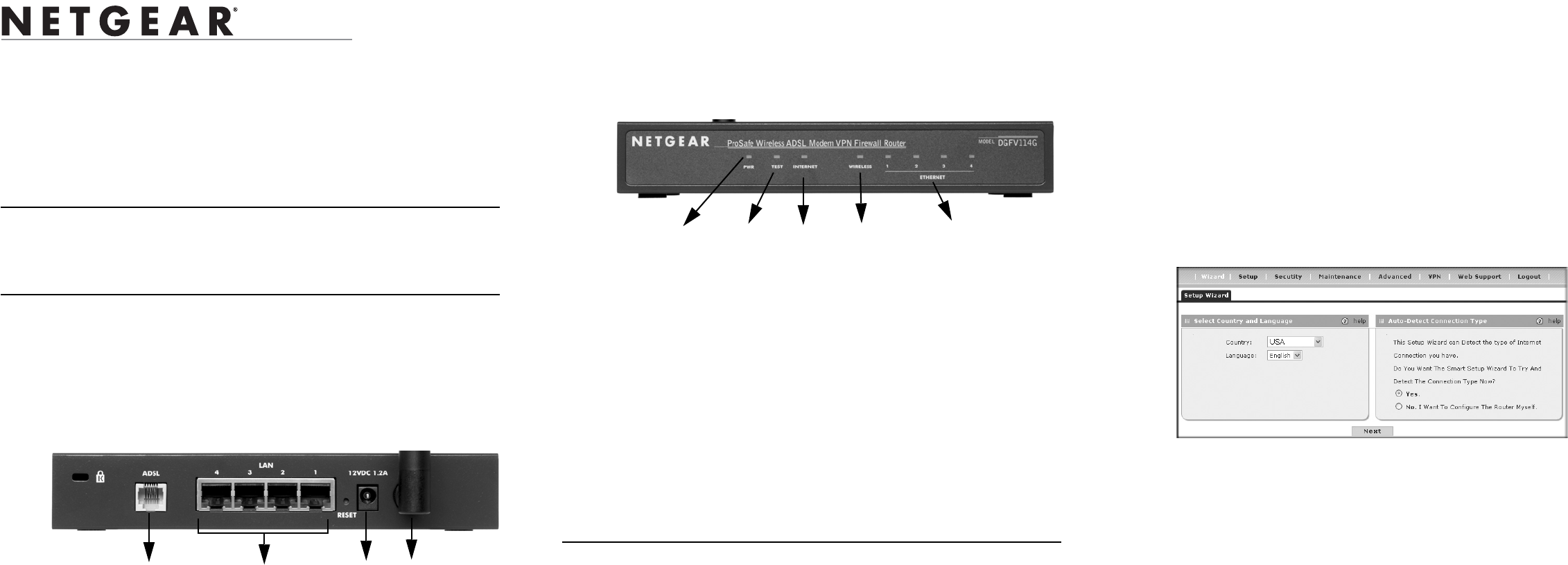
1. CONNECT THE ANTENNA TO THE DGFV114G.
Attach the antenna supplied with the wireless ADSL gateway as shown in (1).
2. CONNECT THE CABLES BETWEEN THE DGFV114G, THE ISP LINE,
AND A COMPUTER
a. Connect the DGFV114G using a direct ADSL connection by inserting the
telephone cable directly into the ADSL WAN port (2) of the DGFV114G.
b. Insert one end of the Ethernet cable that came with your wireless ADSL gateway
into one of the LAN ports on the router (3) and the other end into the Ethernet
port of your computer.
Your network cables are connected and you are ready to restart your network.
3
2 4
1
3. RESTART YOUR NETWORK IN THE CORRECT SEQUENCE
Warning: Failure to restart your network in the correct sequence could prevent you
from connecting to the Internet.
a. Power on the DGFV114G by connecting the power supply to your gateway (4)
and to an AC outlet. Wait one minute.
b. Then, turn on your computer.
c. Check the DGFV114G status lights to verify the following:
•Power: The power light should turn solid green. If it does not turn solid
green, see the Troubleshooting section of the full manual.
•Test: When the router is first turned on, the test light is yellow then goes off.
After two minutes if it is still on, see the Troubleshooting Tips below.
•Internet: The Internet light should be lit indicating that you have a
connection through your ADSL port. If not, make sure that the ADSL line is
securely attached between the router and the phone jack, and that the power
supply is securely attached to the router and plugged into the AC outlet.
•Wireless: The Wireless light will be lit when a computer is connected
wirelessly to your router.
•Ethernet: An Ethernet (LAN) light should be lit. If an Ethernet light is not lit,
check that the Ethernet cable from the computer to the router is securely
attached at both ends, and that the computer is turned on.
Configure the DGFV114G for Internet Access
Before you begin, be sure you have the configuration parameters from your ISP handy.
1. LOG IN TO THE WIRELESS ADSL GATEWAY
Note: To connect to the gateway, your computer needs to be configured to obtain an
IP address automatically, which is usually the case.
Power Test Internet Ethernet Ports (4)
Wireless
a. Use a browser to connect to http://192.168.1.1. For security reasons, the gateway
has its own user name and password.
When prompted, enter admin for the gateway User Name and password for the
gateway password.
b. You are now connected to the gateway.
Select Web Support on the main menu for links to the NETGEAR DGFV114G
product documentation and support knowledge base. Be aware that the default
configuration login time-out is 5 minutes of inactivity, after which automatic logout
will occur.
2. CONNECT TO THE INTERNET
Configure your ISP connection for Internet access:
a. Select Wizard from the main menu. The Setup Wizard screen will display. Select
your Country and Language from the pull-down menus.The text in the web-
based GUI will change to match your selected language.
b. Select the Yes radio button to enable the Setup Wizard and allow the wizard to
detect your ISP connection automatically; or select the No radio button to
configure the router yourself. (Selecting Yes to enable the Setup Wizard is
recommended.)
c. Click Next. The wizard will detect your connection type. Enter any Login or
Password fields required by your ISP and click Apply.
d. Click Test to verify that your Internet connection is active.
If you need to make further modifications, please see the reference manual which is
available by selecting Web Support > Documentation from the main menu.
July 2007
This symbol was placed in accordance with the European Union Directive 2002/
96 on the Waste Electrical and Electronic Equipment (the WEEE Directive). If
disposed of within the European Union, this product should be treated and
recycled in accordance with the laws of your jurisdiction implementing the
WEEE Directive.
© 2007 by NETGEAR, Inc. All rights reserved.
NETGEAR, the NETGEAR logo and ProSafe are trademarks or registered trademarks of NETGEAR, Inc. in the
United States and/or other countries.Other brand and product names are trademarks or registered trademarks of
their respective holders. Information is subject to change without notice.
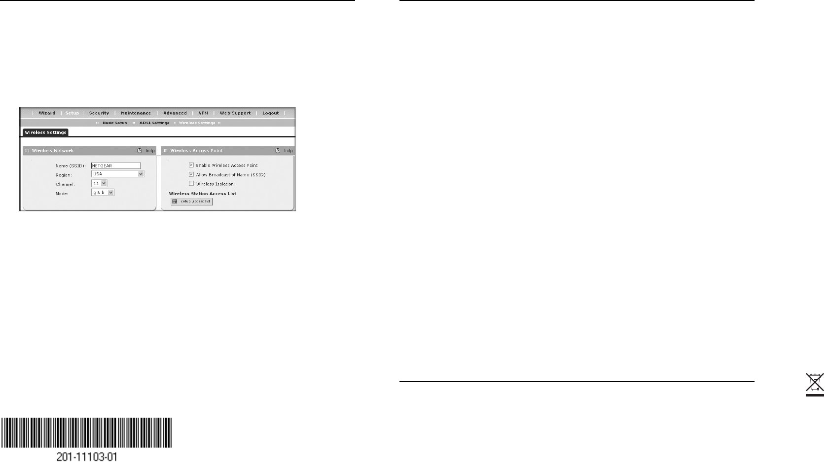
Now, Configure Wireless Connectivity
1. Select Setup > Wireless Settings from the main menu. The Wireless Settings screen
will display.
2. Enter the name or SSID of your wireless network. The default is NETGEAR.
3. Select the correct Country/Region setting so that you are sure to comply with local
regulatory requirements.
4. Select the appropriate Channel (11 is the default) and Operating Mode for your area
(g and b is the default).
5. Select the Enable Wireless Access Point radio button to turn on the wireless radio
and select the Allow Broadcast of Name (SSID) radio button.
6. Configure the Wireless Station Access List and Wireless Security settings according
to the requirements of your network.
7. Click Apply to save your settings.
Verify wireless connectivity. Connect to the Internet or log in to the DGFV114G from a
computer with a wireless adapter that is configured to match the settings you just applied
to your DGFV114G. For wireless connectivity problems, see the Troubleshooting Tips
below or in the DGFV114G ProSafe Wireless ADSL Modem VPN Firewall Router
Reference Manual. A documentation link to the manual is available on the Resource CD
or from the main menu of the user interface under Web Support > Documentation.
Troubleshooting Tips
Here are some tips for correcting common problems you may encounter.
Be sure to restart your network in this sequence:
1. Turn off the DGFV114G and shut down the computer.
2. Wait two minutes.
3. Turn on the DGFV114G. Wait one minute.
4. Turn on the computer.
Make sure the network cables are securely plugged in.
• The DSL Internet status light on the wireless ADSL gateway will be lit if the phone
cable to the ADSL outlet is plugged in securely, the wireless ADSL gateway turned
on and synchronized to the ADSL network.
• For each powered on computer connected to the wireless ADSL gateway with a
securely plugged in Ethernet cable, the corresponding wireless ADSL gateway
Ethernet port status light will be lit. The front of the DGFV114G identifies the
number of each Ethernet (LAN) port.
Make sure the network settings of the computer are correct.
Computers should be configured to obtain IP addresses automatically via DHCP. For help
with this, please see the links in the appendix of the Reference Manual.
Use the DGFV114G status lights to verify correct operation.
If the DGFV114G Test light does not go out within two minutes of turning the router on,
reset the router as described in the Reference Manual.
Make sure the computer and DGFV114G wireless settings
match exactly.
The Wireless Network Name (SSID) and security settings (WEP/WPA, MAC access
control list) of the DGFV114G and wireless computer must match exactly.
Technical Support
Thank you for selecting NETGEAR products.
After completing router setup, locate the serial number on the bottom label of your
product and use it to register your product at http://www.NETGEAR.com/register.
Registration on the web site or over the phone is required before you can use our
telephone support service. The phone numbers for worldwide regional customer support
centers are on the Warranty and Support Information card that came with your product.
Go to http://kbserver.netgear.com for product updates and web support.

Regulatory Approvals
FCC Statement
This equipment has been tested and found to comply with the limits for a Class B digital
device, pursuant to Part 15 of the FCC Rules. These limits are designed to provide reasonable
protection against harmful interference in a residential installation.
This equipment generates, uses and can radiate radio frequency energy and, if not installed and
used in accordance with the instructions, may cause harmful interference to radio communica-
tions. However, there is no guarantee that interference will not occur in a particular installation.
If this equipment does cause harmful interference to radio or television reception, which can be
determined by turning the equipment off and on, the user is encouraged to try to correct the
interference by one of the following measures:
Reorient or relocate the receiving antenna.
Increase the separation between the equipment and receiver.
Connect the equipment into an outlet on a circuit different from that to which the receiver
is connected.
Consult the dealer or an experienced radio/TV technician for help.
To assure continued compliance, any changes or modifications not expressly approved by the
party responsible for compliance could void the user's authority to operate this equipment.
(Example - use only shielded interface cables when connecting to computer or peripheral
devices).
FCC Radiation Exposure Statement
This equipment complies with FCC RF radiation exposure limits set forth for an uncontrolled
environment. This equipment should be installed and operated with a minimum distance of 20
centimeters between the radiator and your body.
This device complies with Part 15 of the FCC Rules. Operation is subject to the following two
conditions:
(1) This device may not cause harmful interference, and
(2) This device must accept any interference received, including interference that may cause
undesired operation.
This transmitter must not be co-located or operating in conjunction with any other antenna or
transmitter.
The antennas used for this transmitter must be installed to provide a separation distance of at
least 20 cm from all persons and must not be co-located or operating in conjunction with any
other antenna or transmitter.
Channel
The Wireless Channel sets the radio frequency used for communication.
•Access Points use a fixed Channel. You can select the Channel used. This allows you to
choose a Channel which provides the least interference and best performance. In the USA
and Canada, 11 channel are available. If using multiple Access Points, it is better if adjacent
Access Points use different Channels to reduce interference.
• In "Infrastructure" mode, Wireless Stations normally scan all Channels, looking for an
Access Point. If more than one Access Point can be used, the one with the strongest
signal is used. (This can only happen within an ESS.)
• If using "Ad-hoc" mode (no Access Point), all Wireless stations should be set to use the
same Channel. However, most Wireless stations will still scan all Channels to see if there
is an existing "Ad-hoc" group they can join.
Note:This equipment marketed in USA is restricted by firmware to only operate on 2.4G channel 1-11
.