Netgear orporated 08200084 ProSafe Wireless-N VPN Firewall User Manual FullManual
Netgear Incorporated ProSafe Wireless-N VPN Firewall FullManual
UserManual.wiki
>
Netgear orporated
>
08200084 User Manual
>
Manual part 1
Contents
1.
Manual part 1
2.
Manual part 2
Manual part 1
Navigation menu
Upload a User Manual
Namespaces
Wiki Guide
HTML
PDF
Info
Views
User Manual
Discussion / Help
Navigation


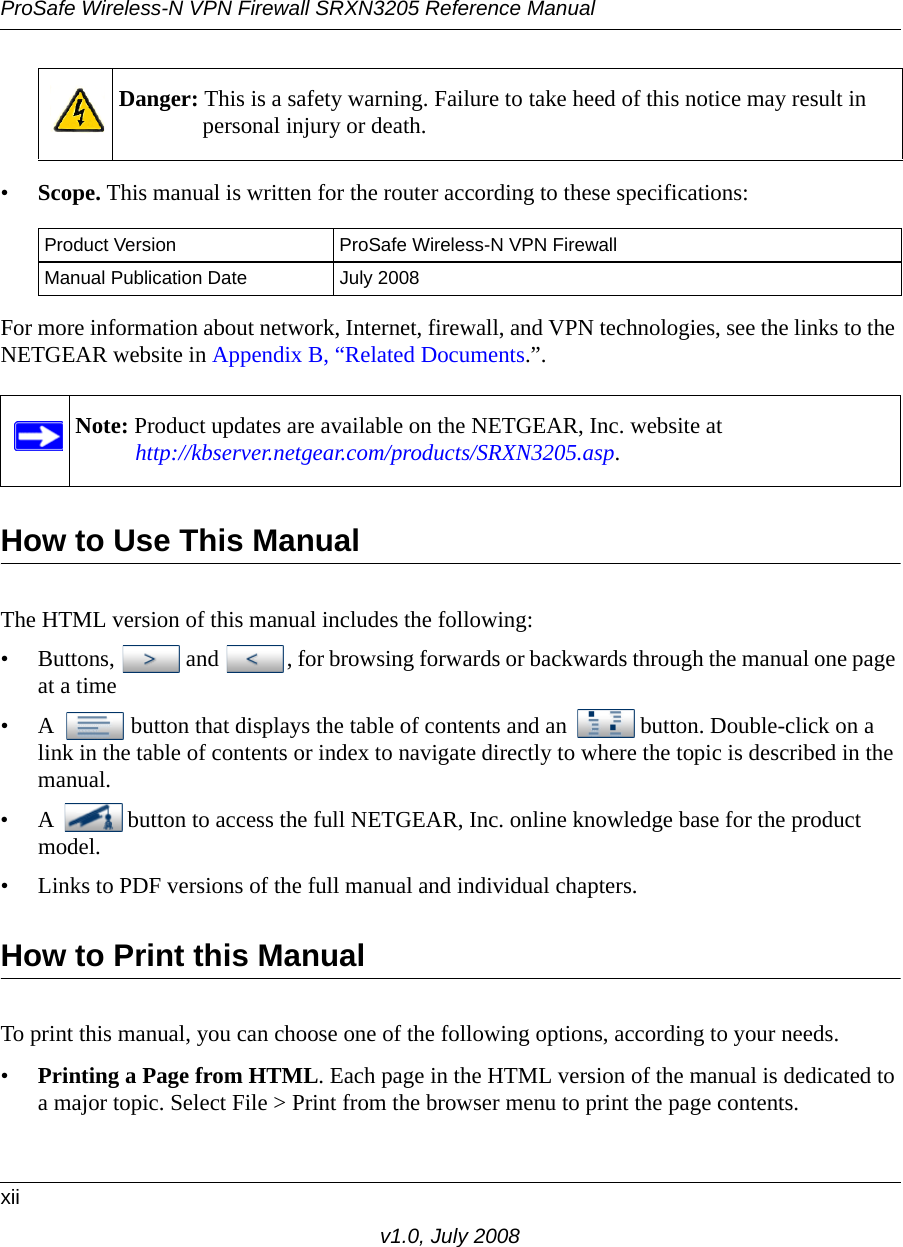


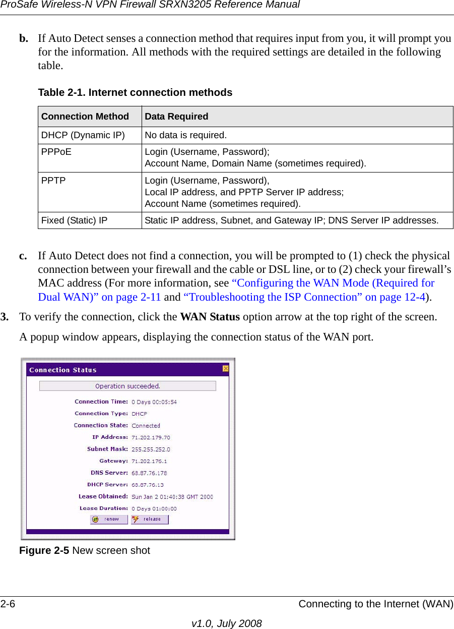

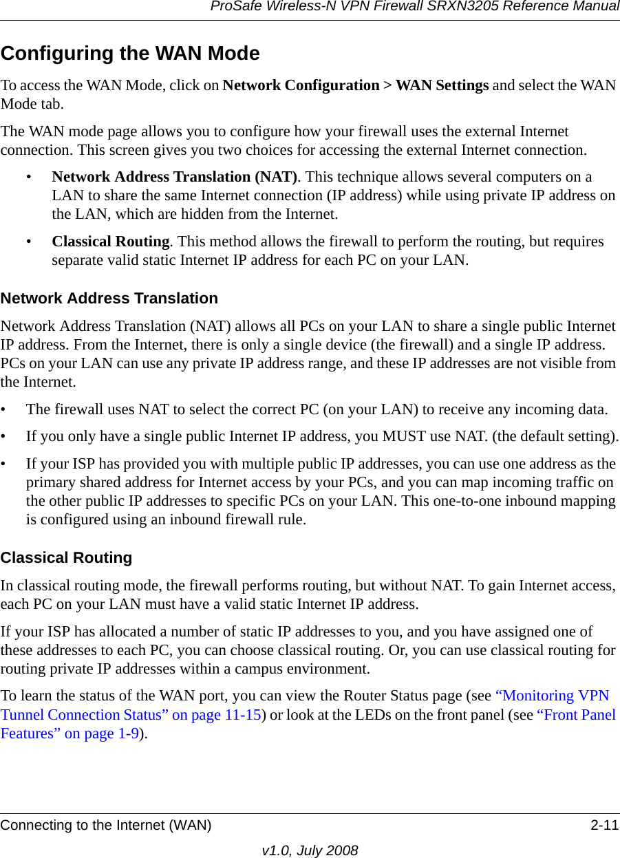


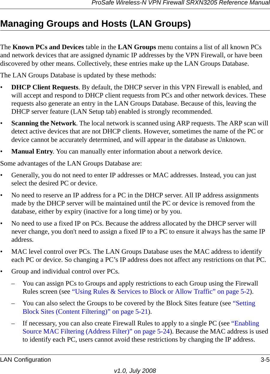


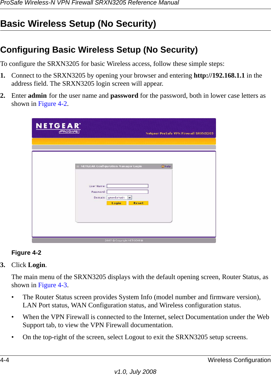
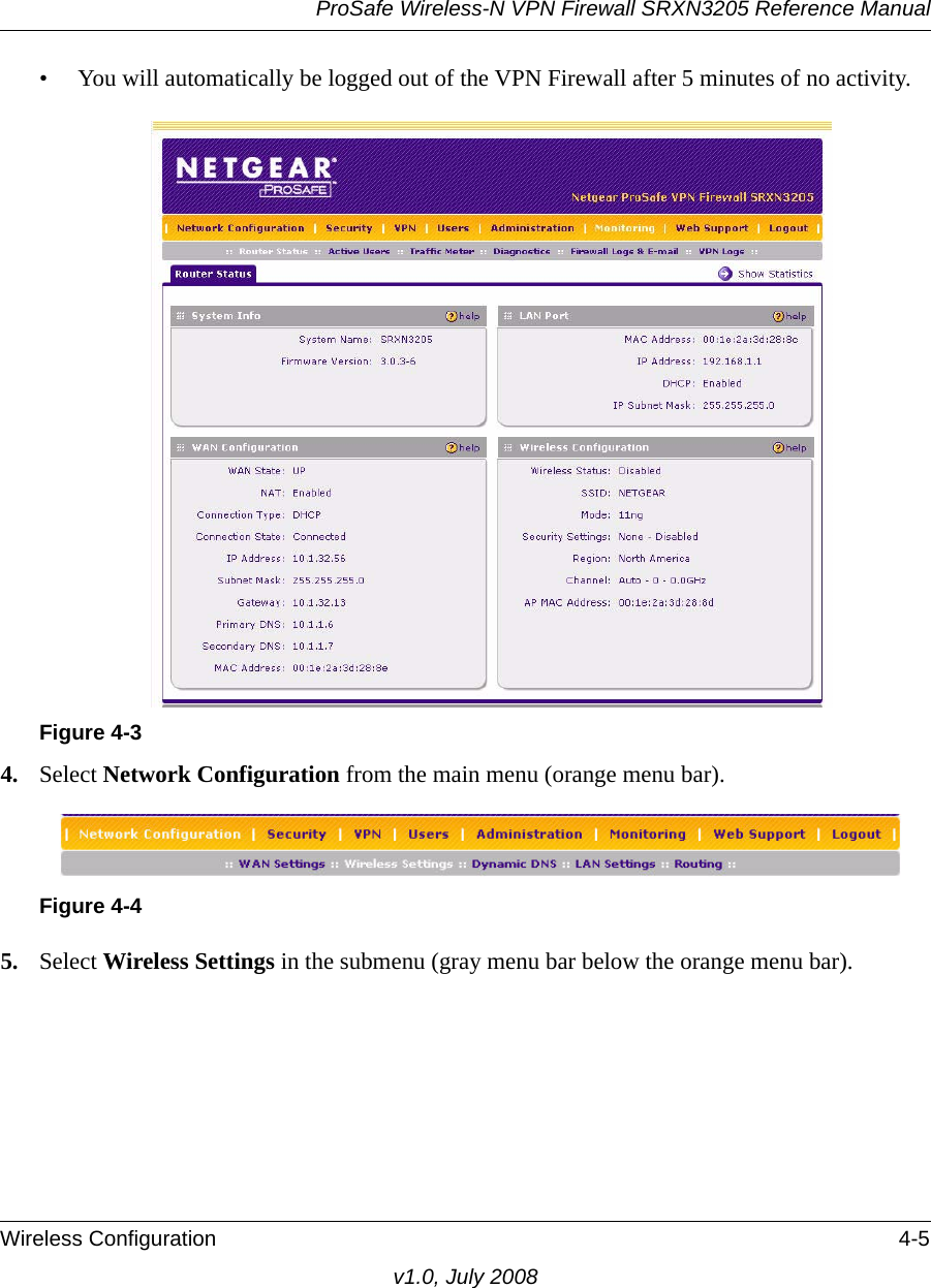

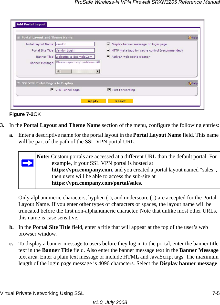
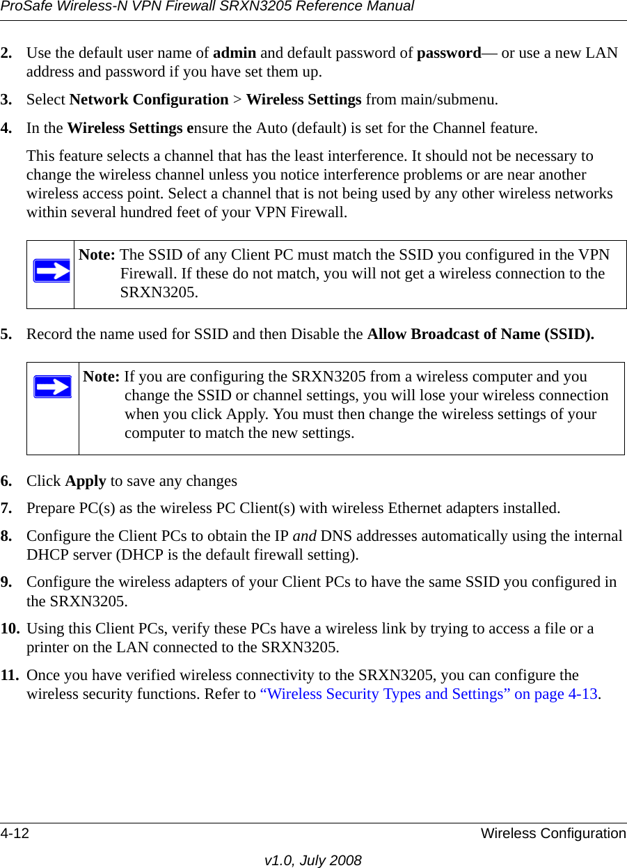
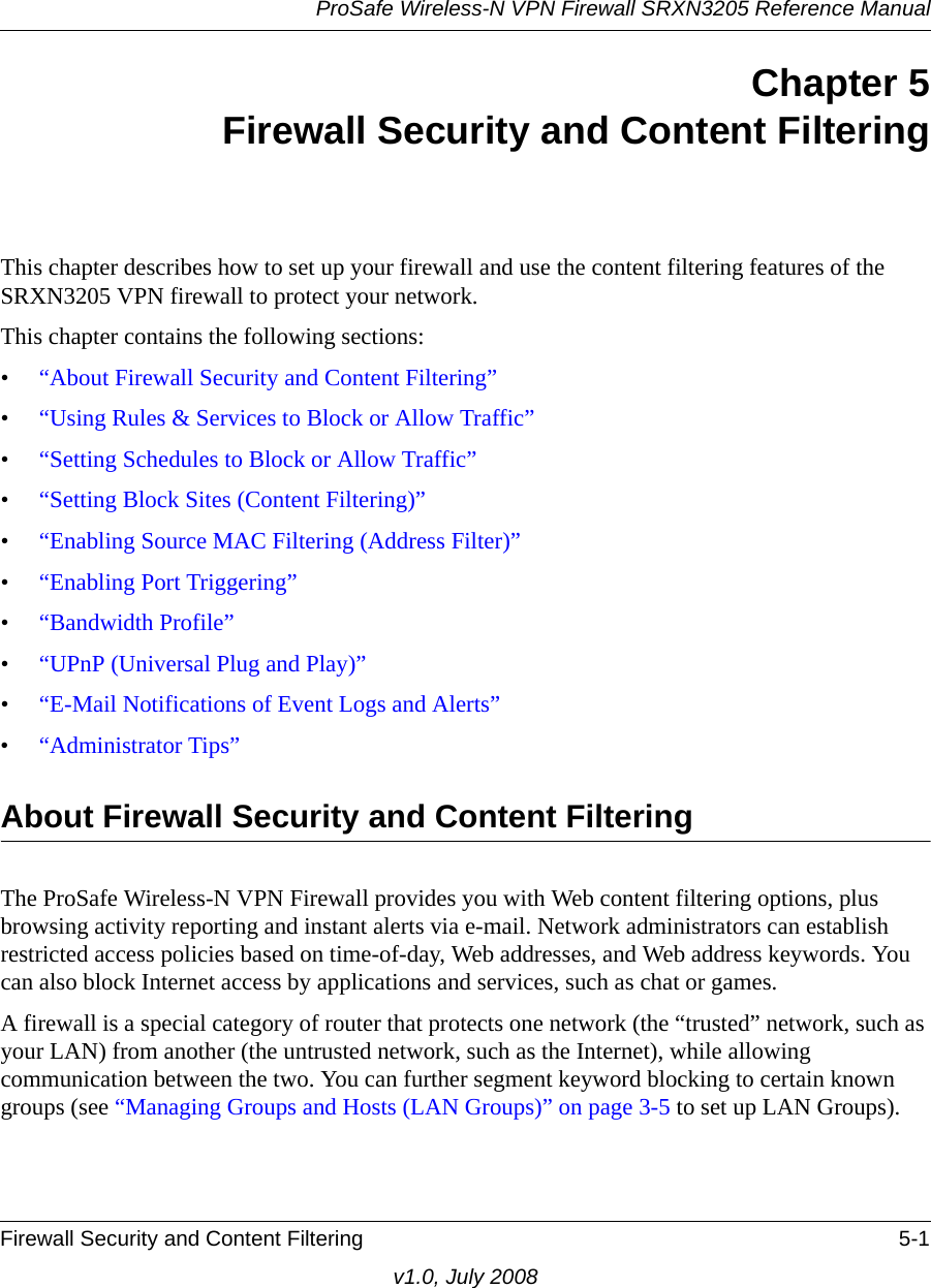
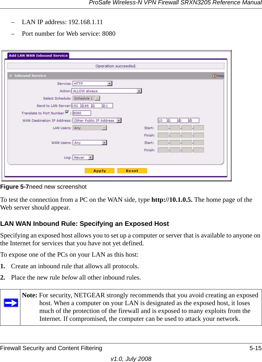
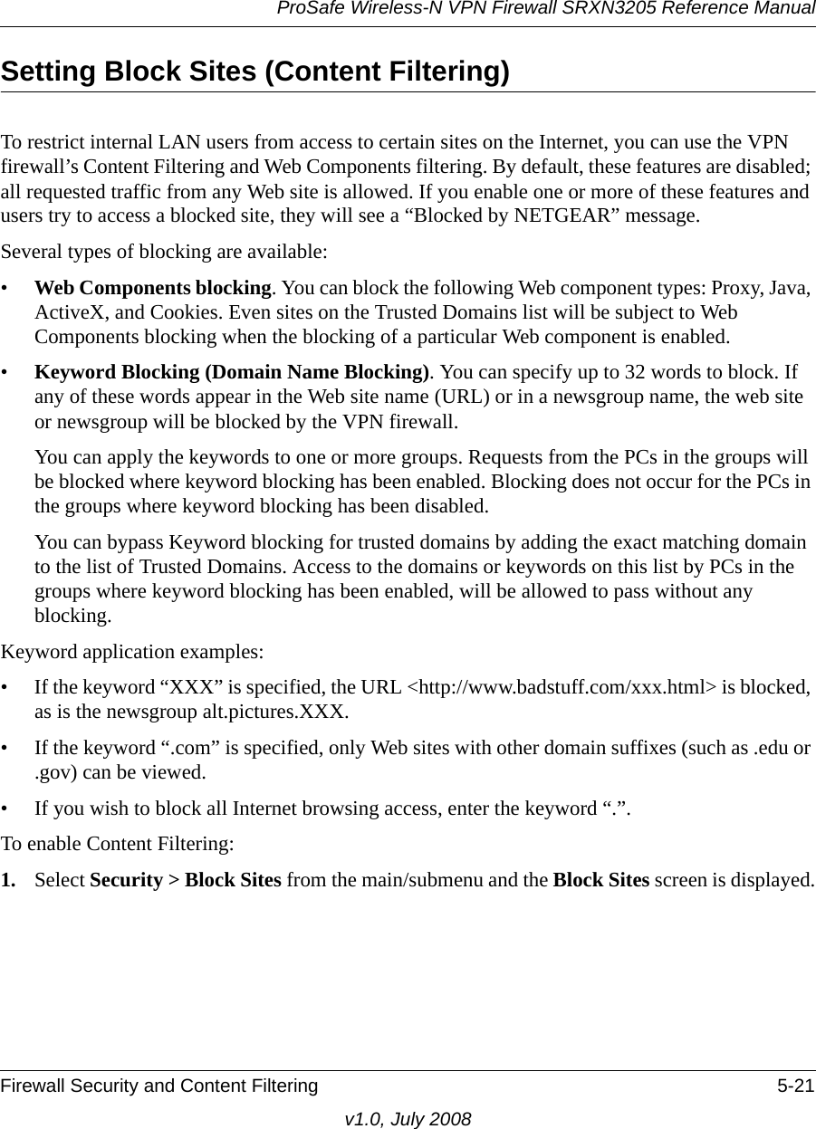
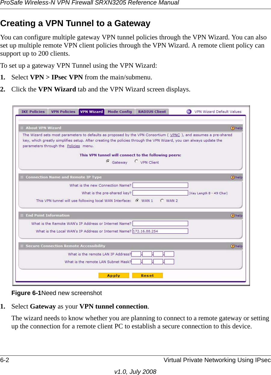
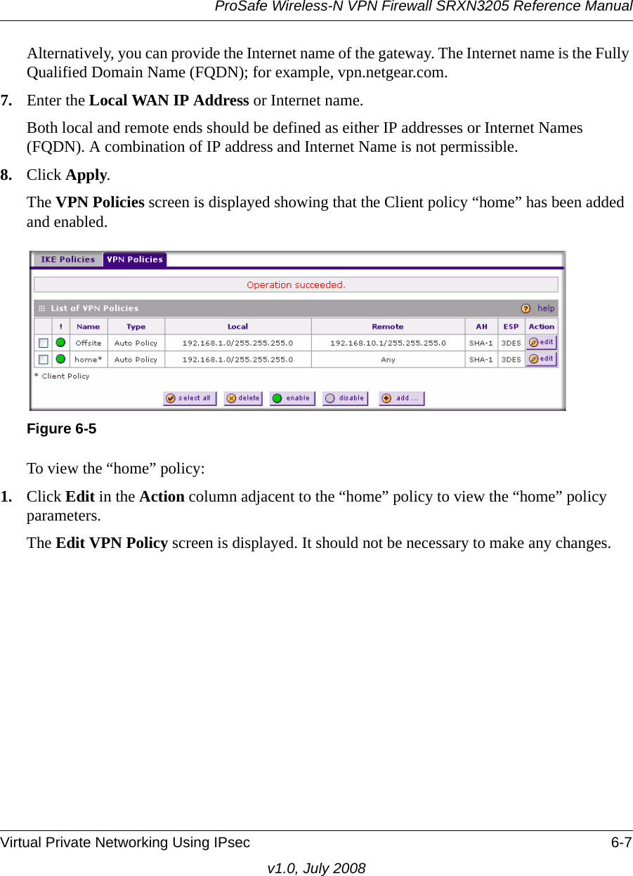
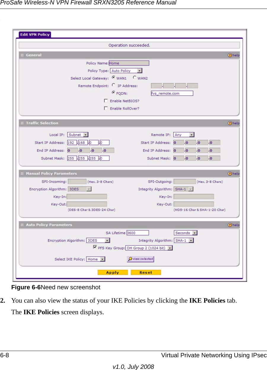
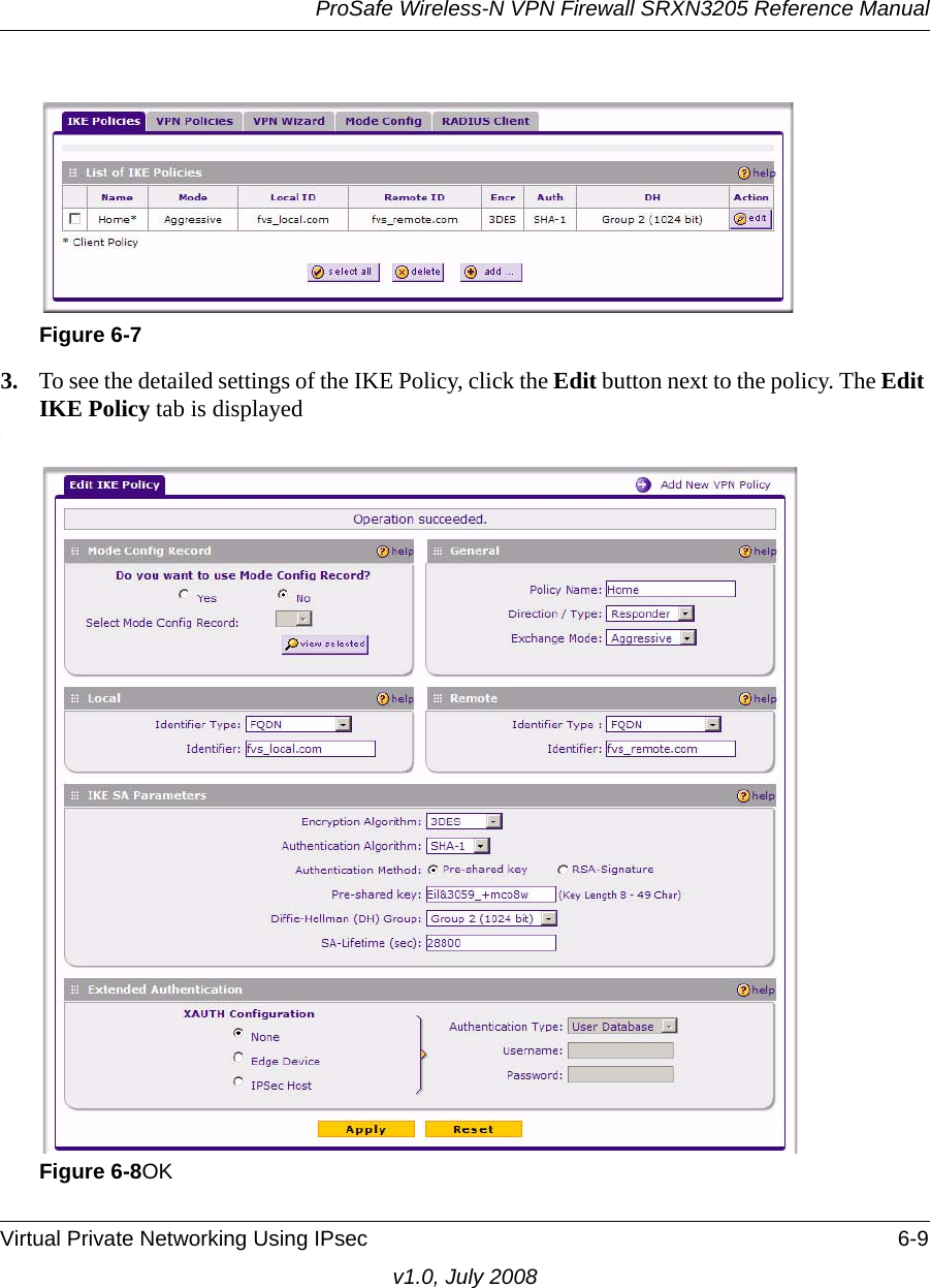
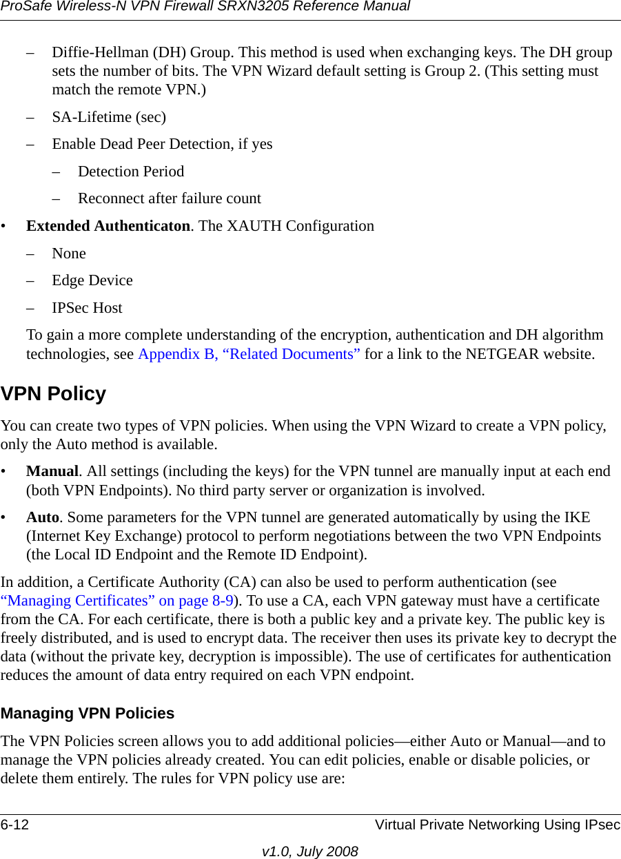
![ProSafe Wireless-N VPN Firewall SRXN3205 Reference ManualWireless Configuration 4-7v1.0, July 20088. Type your network name in the Name (SSID) field on the upper left side of the screen. 9. From the Region pull-down menu, select the region where the SRXN3205 will be used (the default Region is North America).10. Select your wireless Mode setting from the pulldown menu or accept the default (11ng) setting.The selection are 802.11[a only, b only, g only, g and b, 11ng, or 11a].(When you change the Mode setting and Click Apply, the SRXN3205 will reboot to accept the change. This is a bug??)11. Leave the other settings in the upper left portion of the screen at the defaults.12. Leave None selected as the Wireless Security Type for the basic wireless test. 13. Click Apply at the bottom of the Wireless Settings screen.If the settings were accepted, a message appears in the center of the screen, Operation succeeded.Testing Basic Wireless Access (No Security)1. Prepare a PC as the wireless PC Client with a wireless Ethernet adapter installed. If this PC is already part of your network, record its TCP/IP configuration settings for use later. 2. Configure the Client PC to obtain its IP and DNS addresses automatically using the internal DHCP server (DHCP is the default firewall setting).3. Using this Client PC, try to access a file or a printer on the LAN connected to the SRXN3205. If you have not set up the basic wireless settings mentioned earlier to SRXN3205 with the Host PC, this test will not give satisfactory results. Go to the “Configuring Basic Wireless Setup (No Security)”and set up the SRXN3205 for basic wireless access with no security.Note: If your country or region is not listed, please check with Netgear Support.](https://usermanual.wiki/Netgear-orporated/08200084.Manual-part-1/User-Guide-988502-Page-63.png)


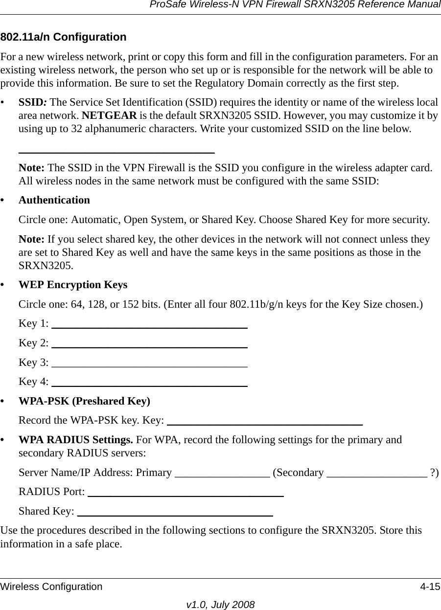


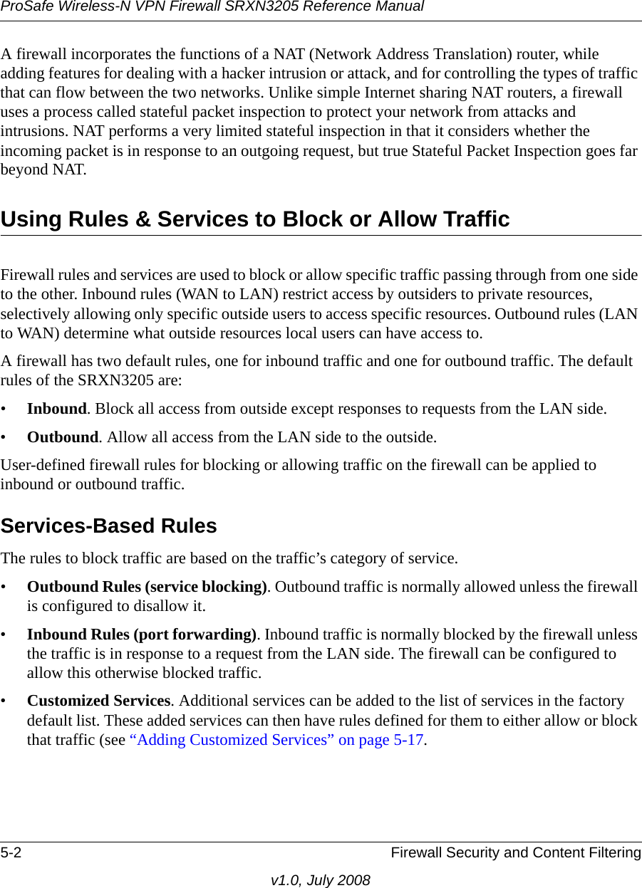


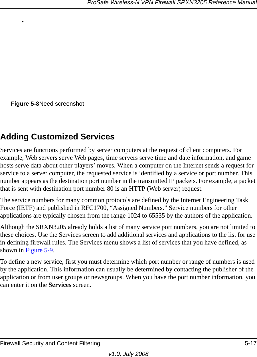
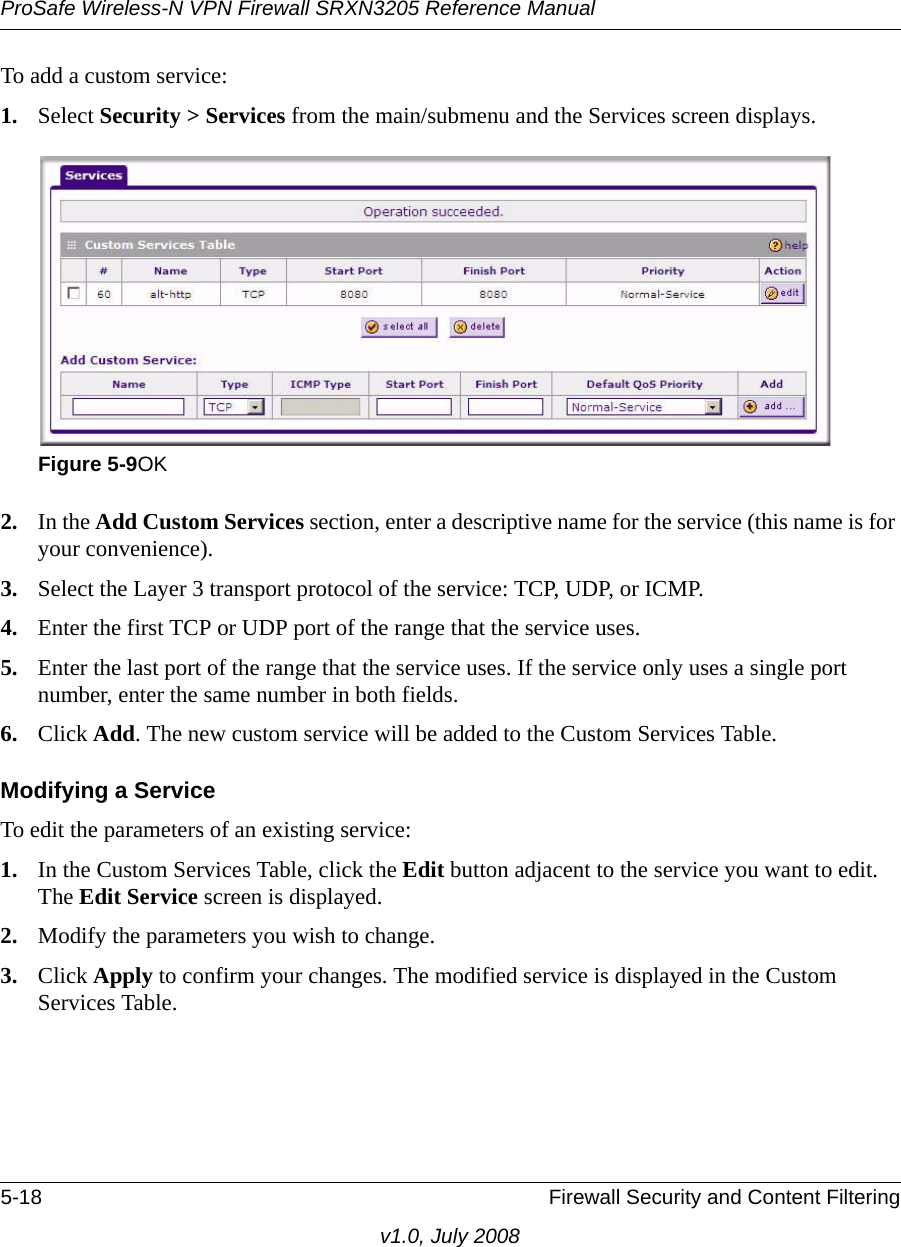
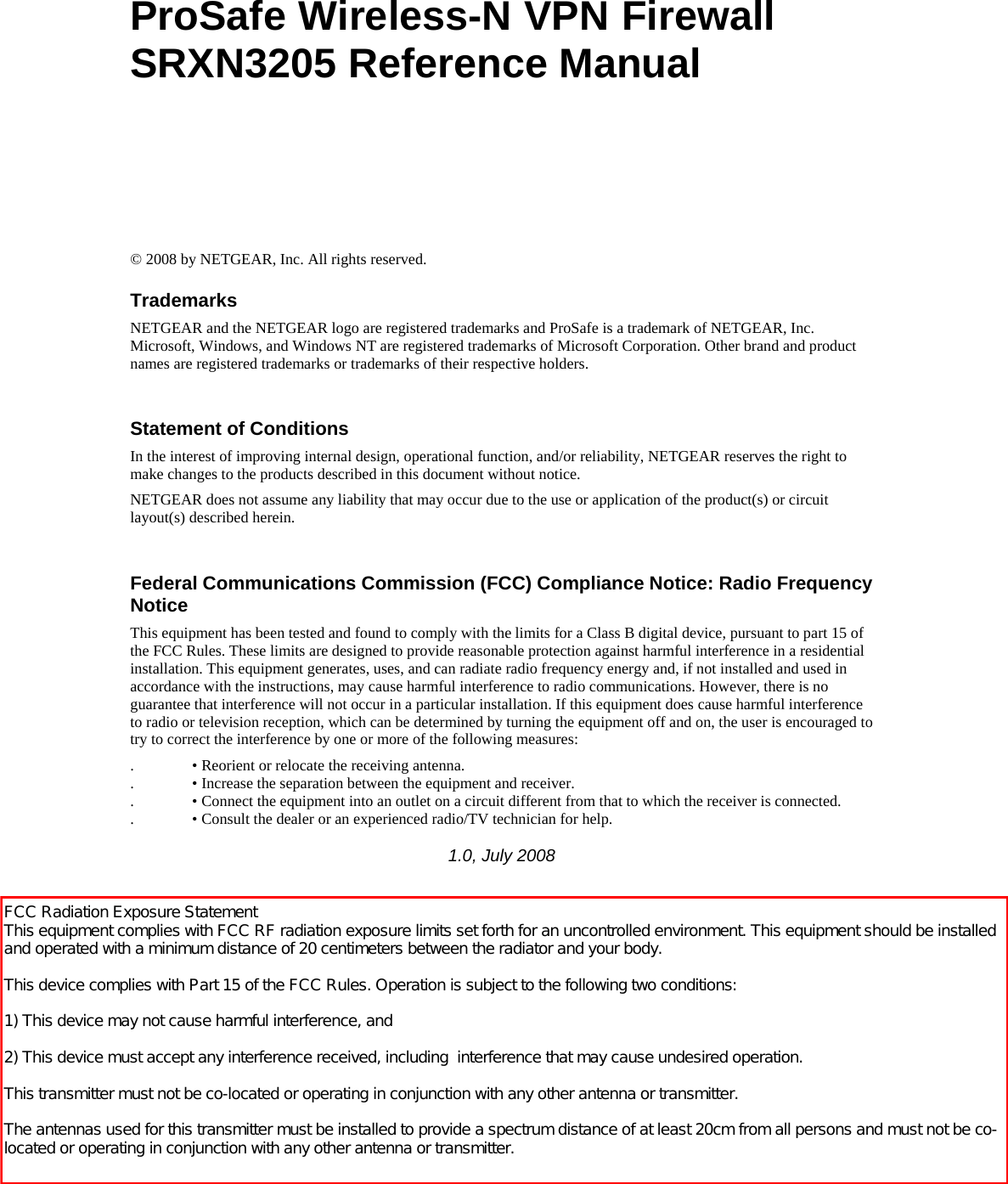
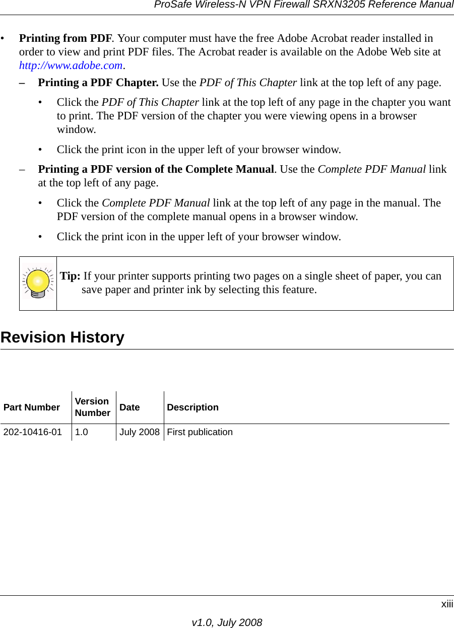
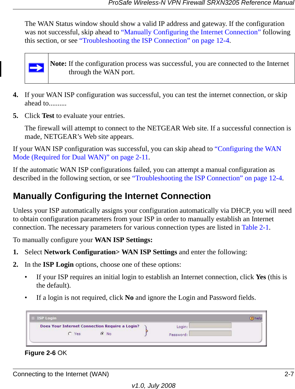
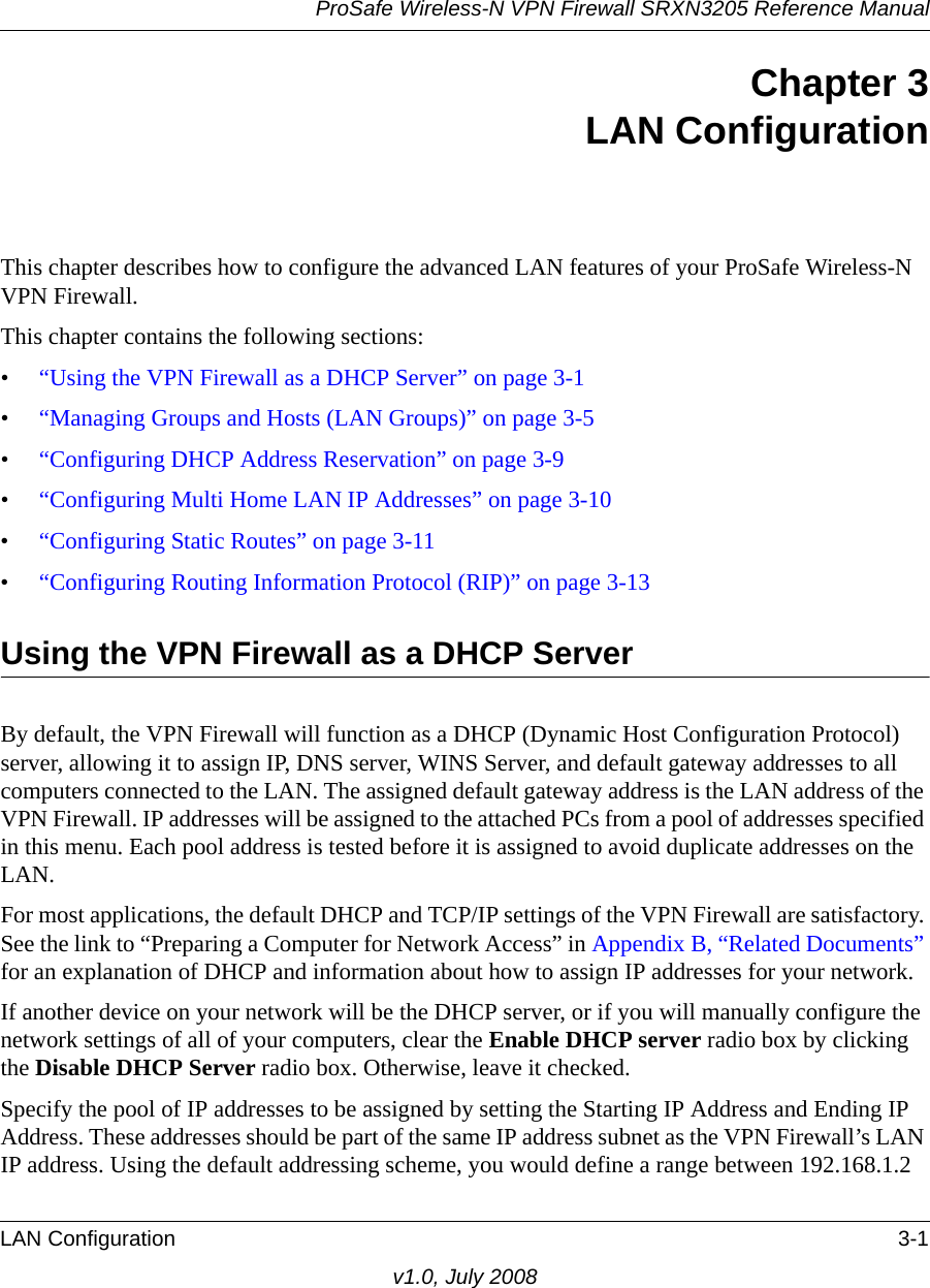
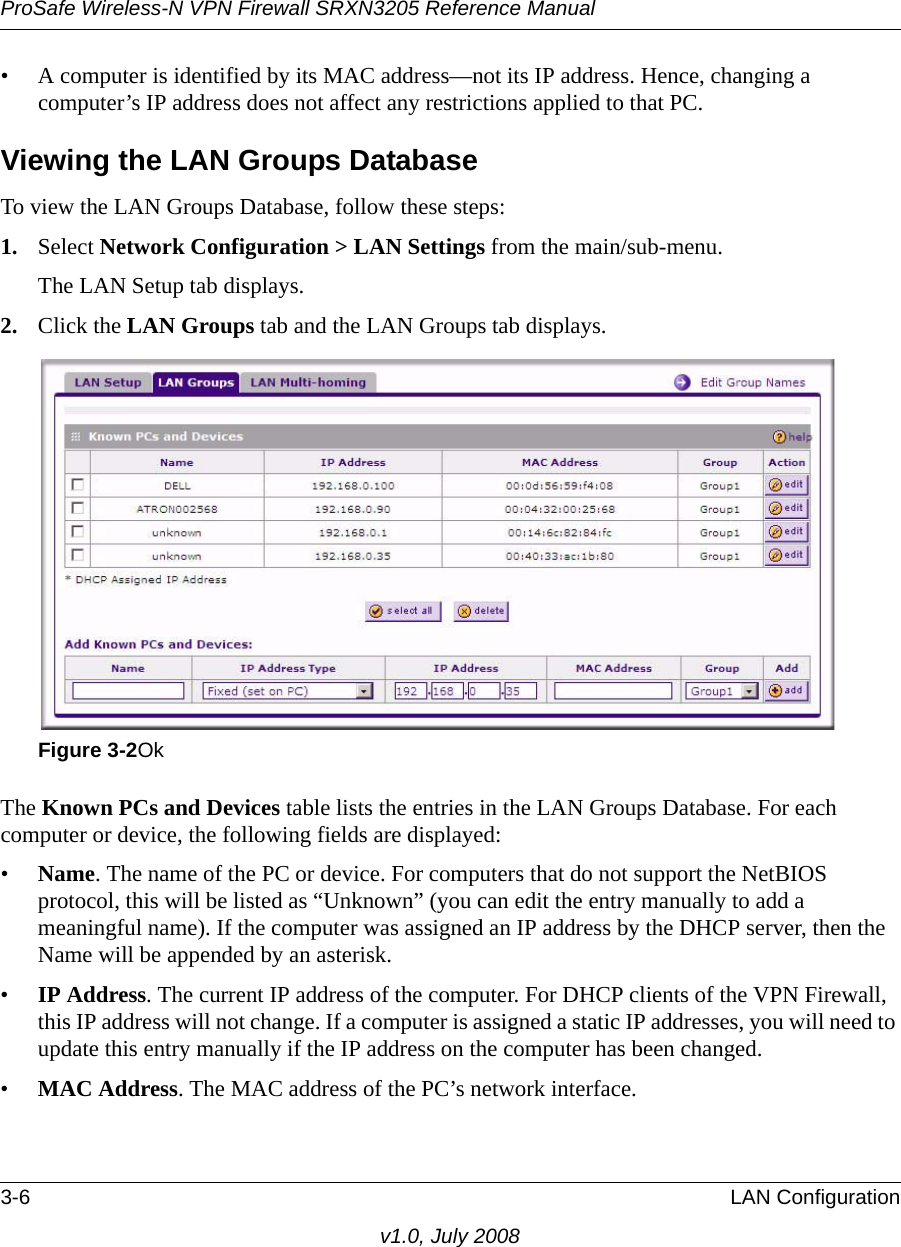
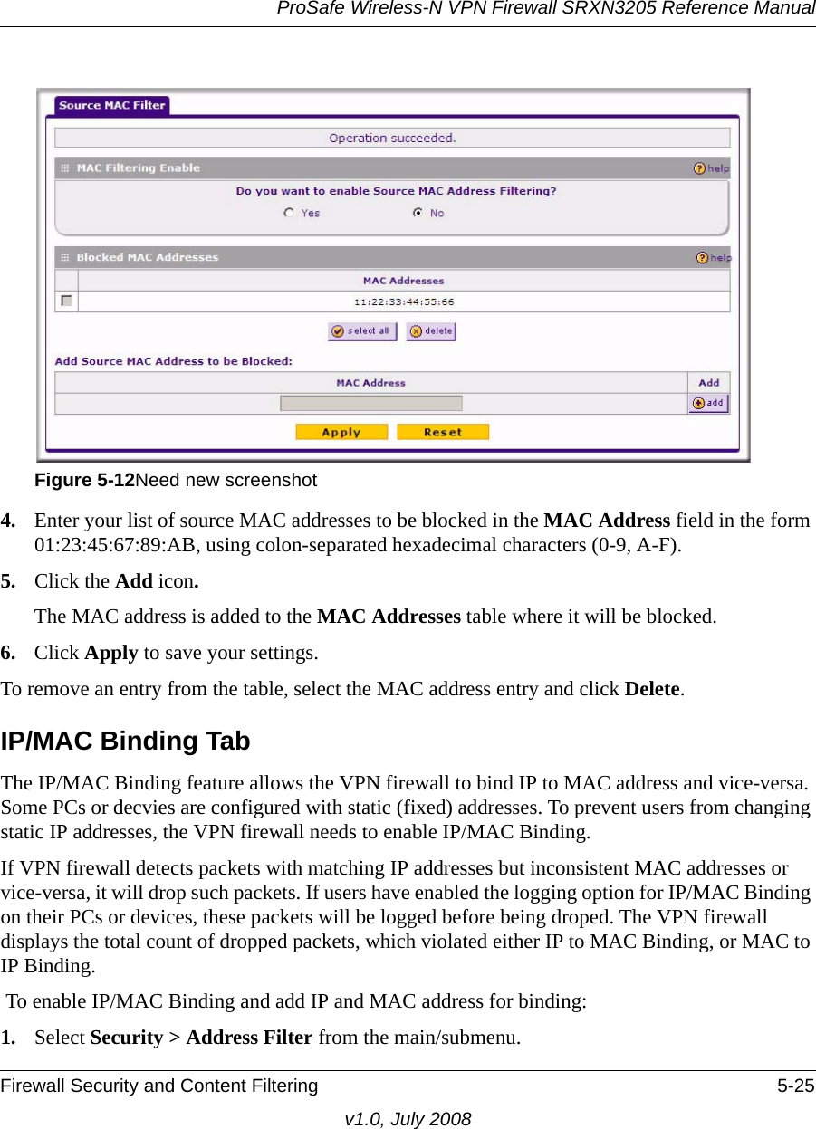
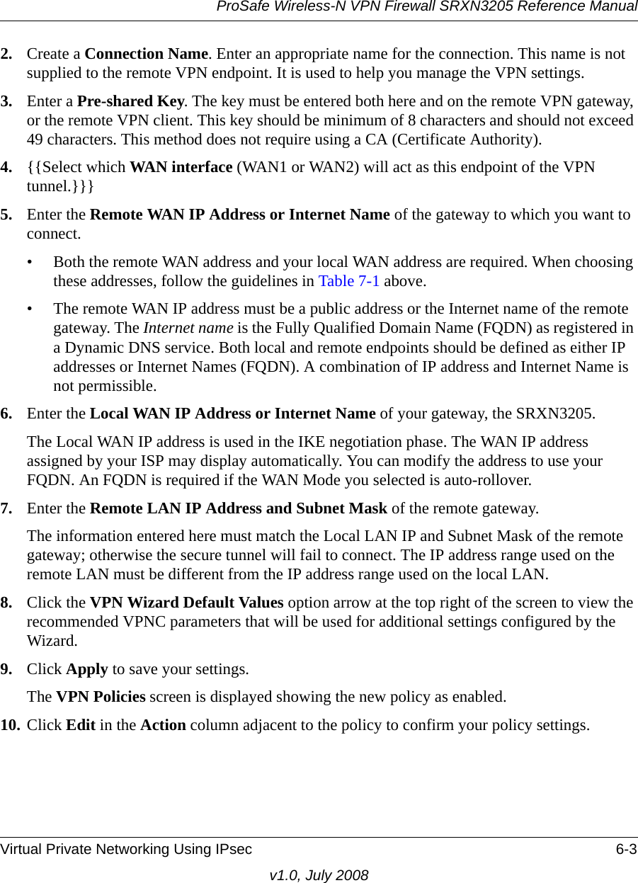
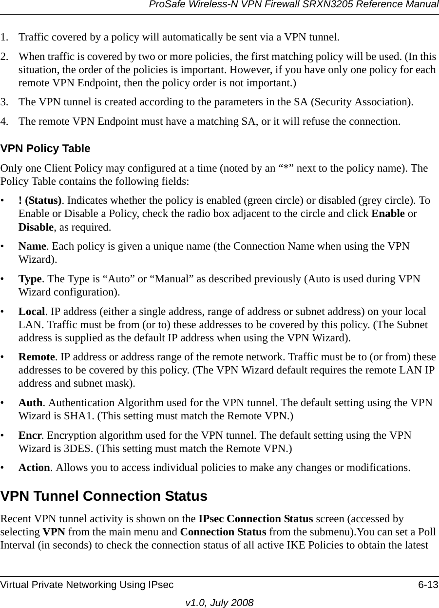
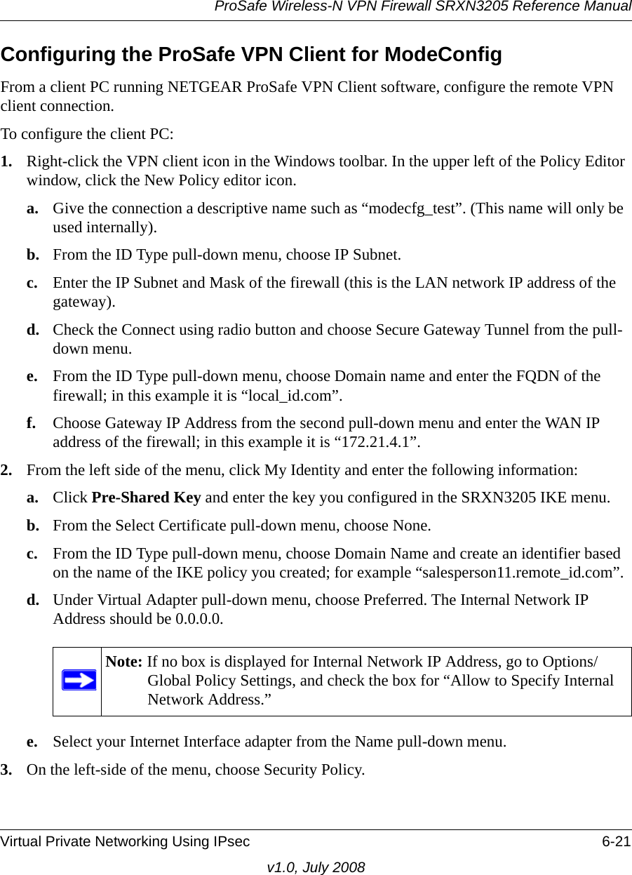
![ProSafe Wireless-N VPN Firewall SRXN3205 Reference ManualFirewall Security and Content Filtering 5-19v1.0, July 2008Setting Quality of Service (QoS) PrioritiesThe Quality of Service (QoS) Priorities setting determines the priority of a service, which in turn, determines the quality of that service for the traffic passing through the firewall. The user can change this priority:•On the Services screen in the Custom Services Table for customized services (see Figure 5-9)[Security > Services].•On the LAN WAN Outbound Services screen (see Figure 5-2) [Security > Firewall > LAN WAN Rules and click Add to the Outbound Services].The QoS priority definition for a service determines the queue that is used for the traffic passing through the firewall. A priority is assigned to IP packets using this service. Priorities are defined by the “Type of Service (ToS) in the Internet Protocol Suite” standards, RFC 1349. A ToS priority for traffic passing through the VPN firewall is one of the following:•Normal-Service. No special priority given to the traffic. The IP packets for services with this priority are marked with a ToS value of 0.•Minimize-Cost. Used when data has to be transferred over a link that has a lower “cost”. The IP packets for services with this priority are marked with a ToS value of 1.•Maximize-Reliability. Used when data needs to travel to the destination over a reliable link and with little or no retransmission. The IP packets for services with this priority are marked with a ToS value of 2.•Maximize-Throughput. Used when the volume of data transferred during an interval is important even if the latency over the link is high. The IP packets for services with this priority are marked with a ToS value of 4.•Minimize-Delay. Used when the time required (latency) for the packet to reach the destination must be low. The IP packets for services with this priority are marked with a ToS value of 8.](https://usermanual.wiki/Netgear-orporated/08200084.Manual-part-1/User-Guide-988502-Page-105.png)
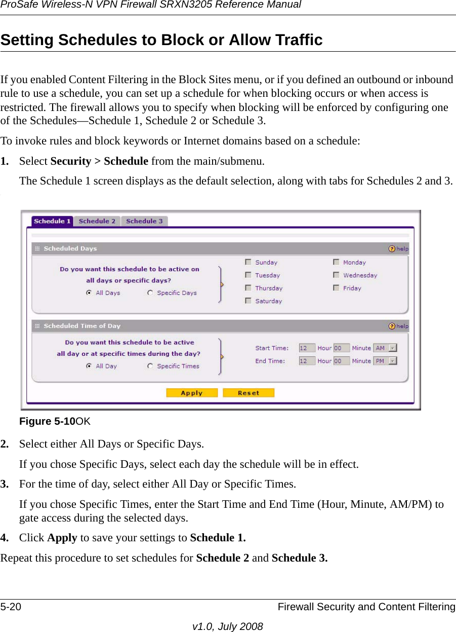


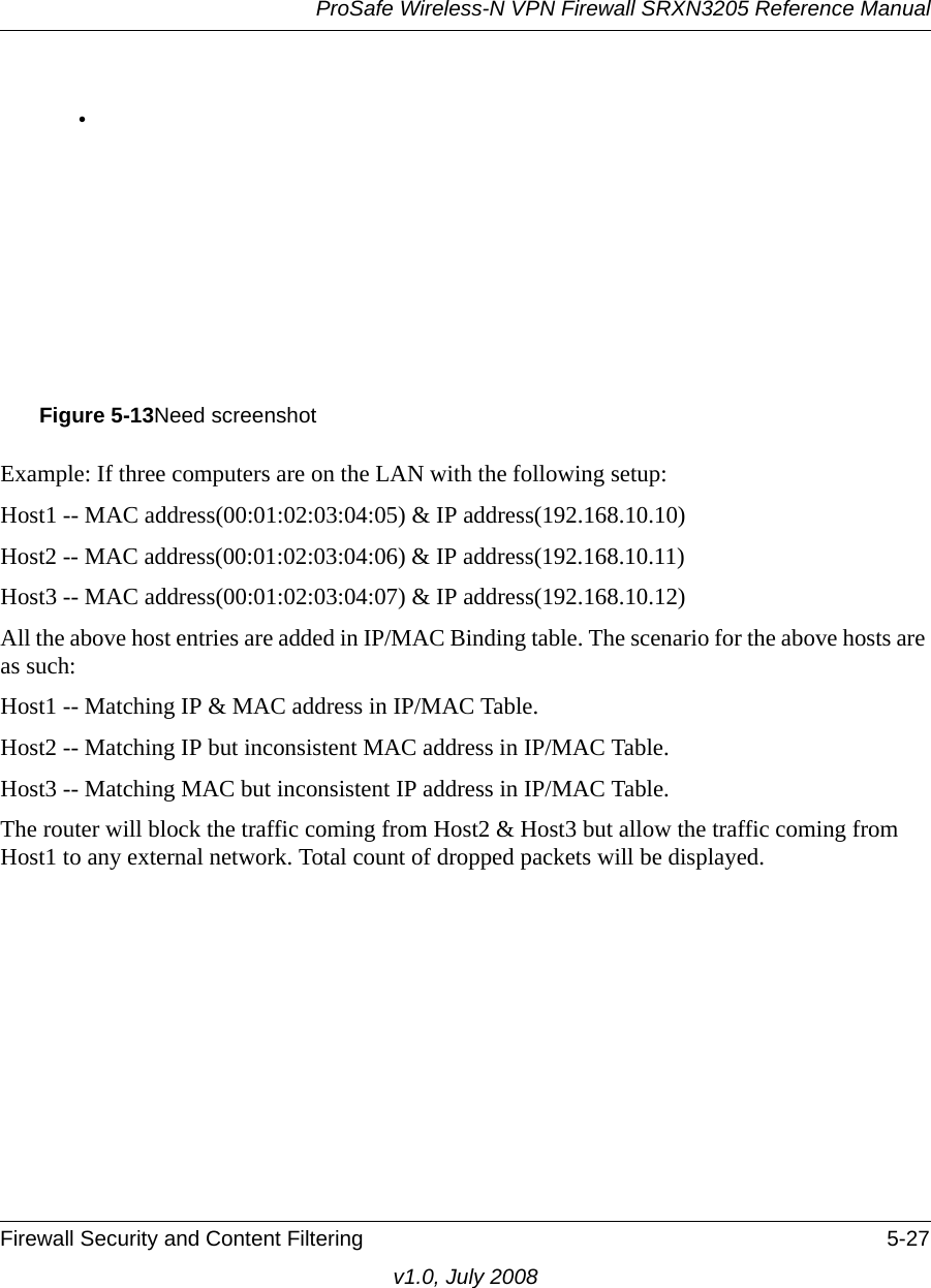


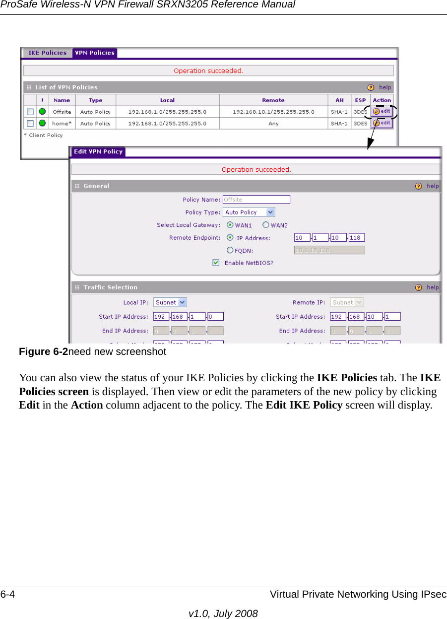


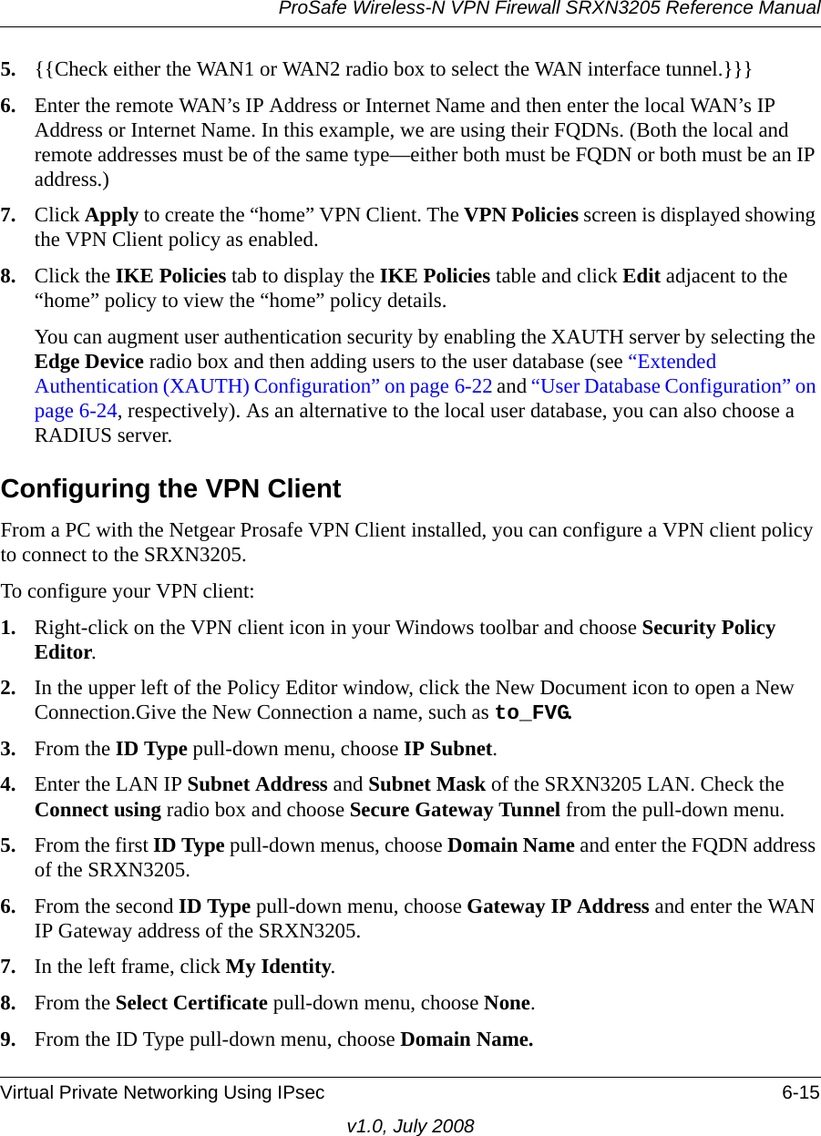


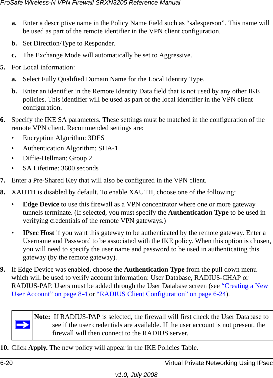
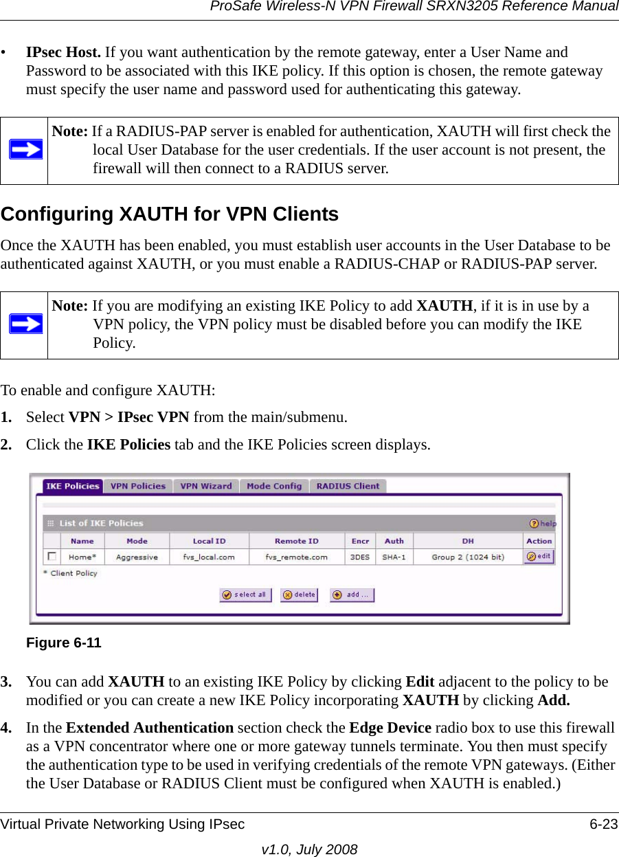
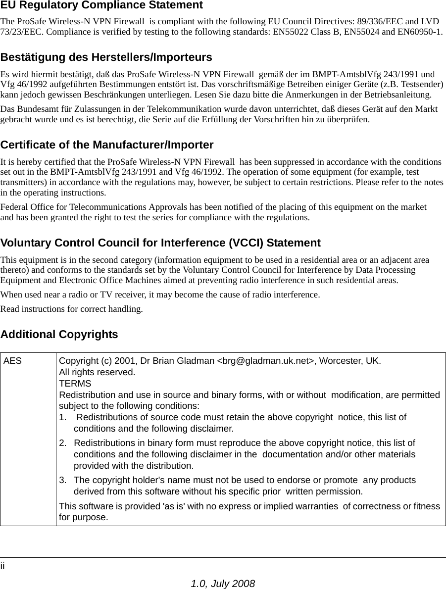
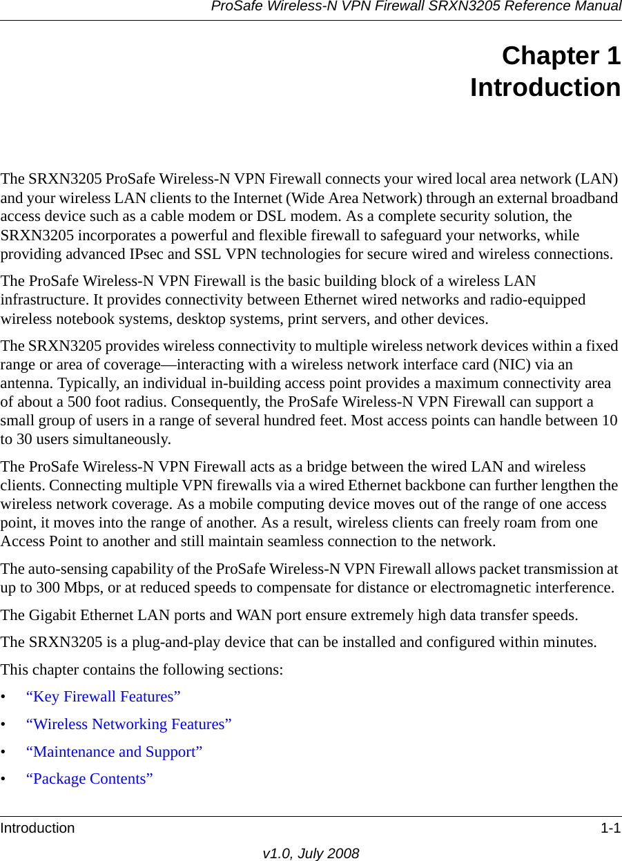
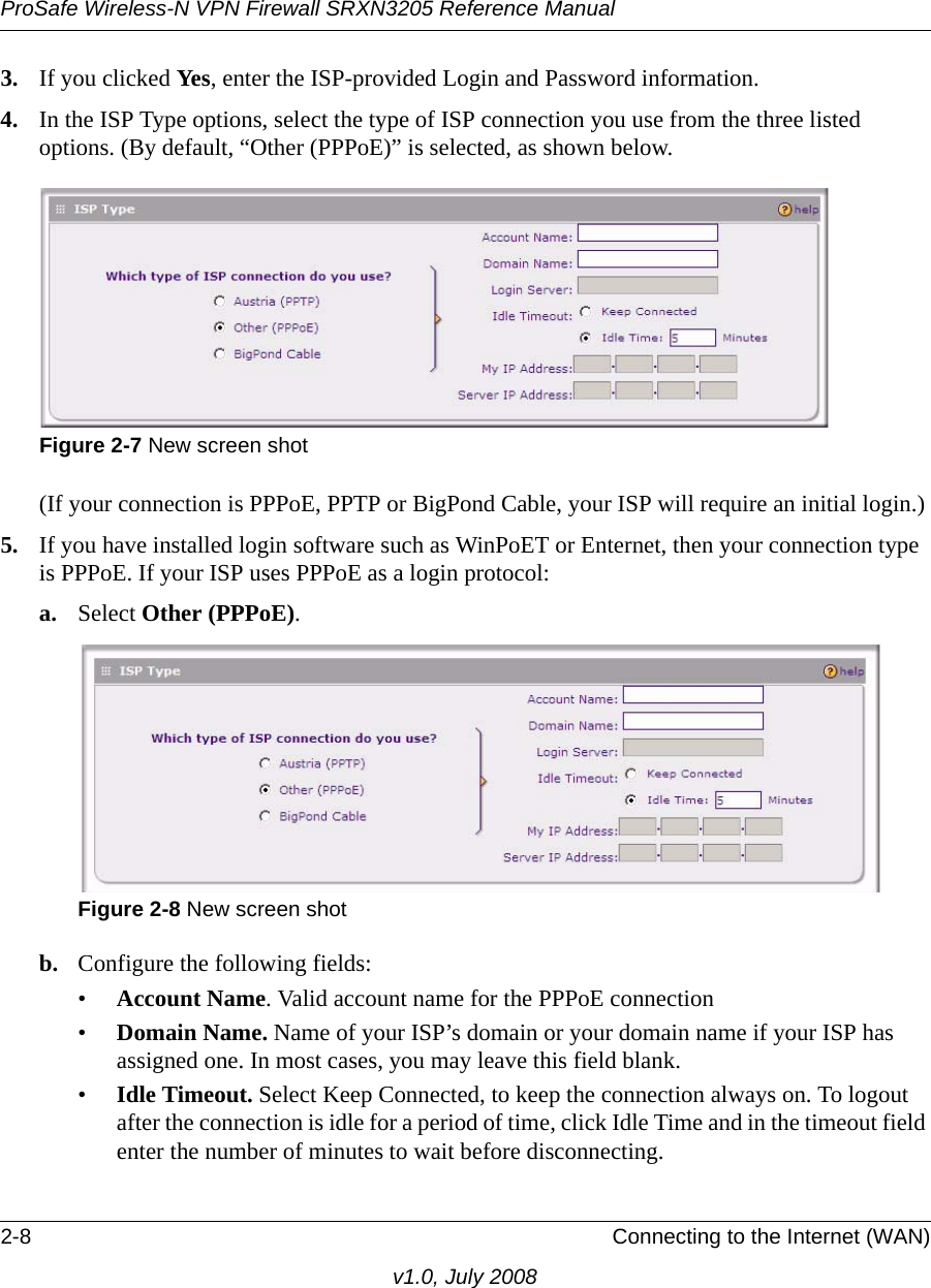
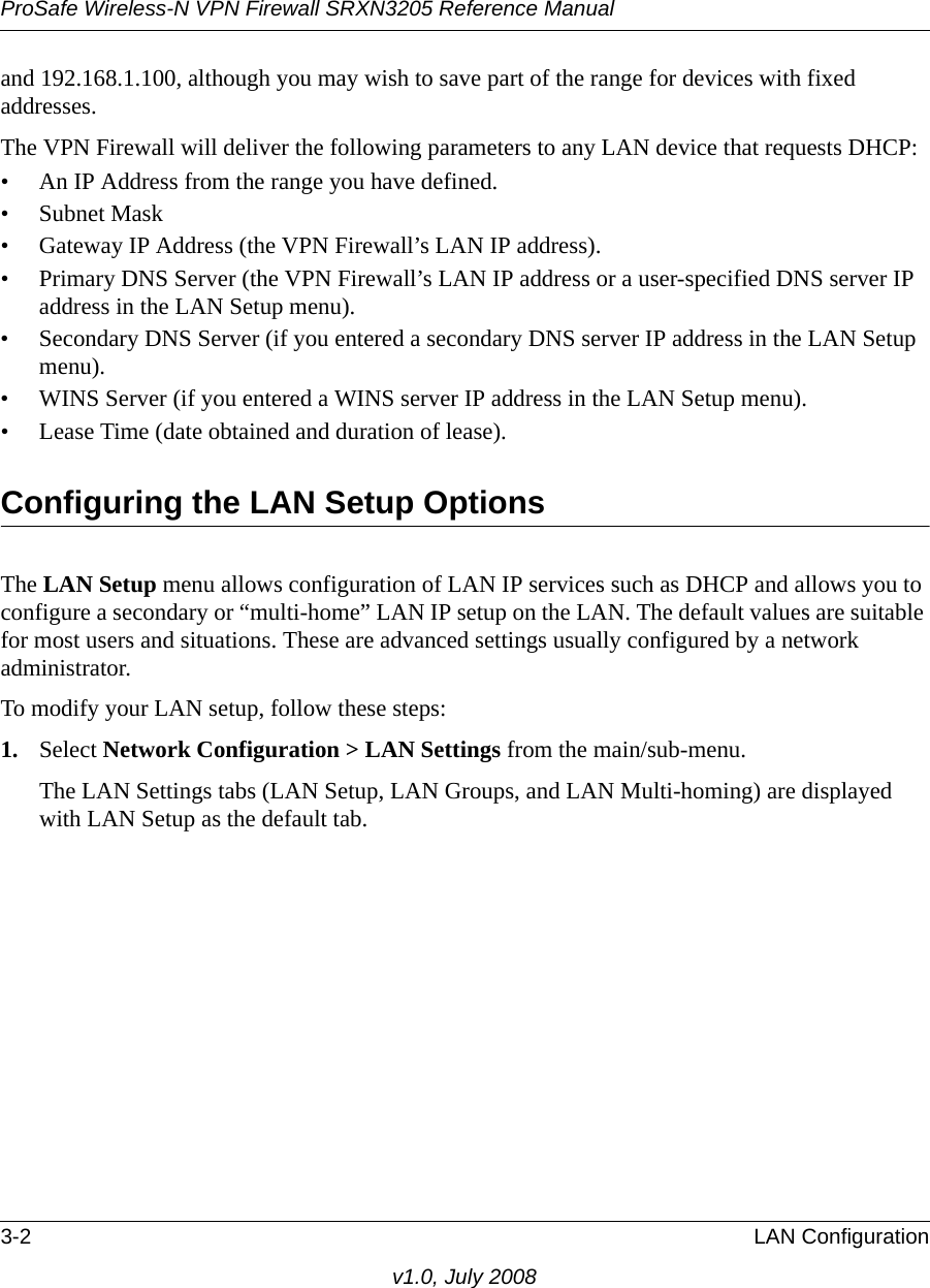
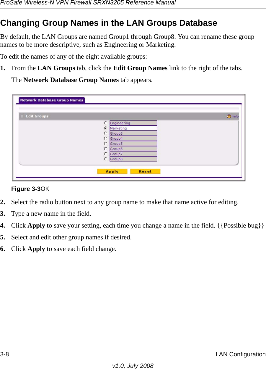
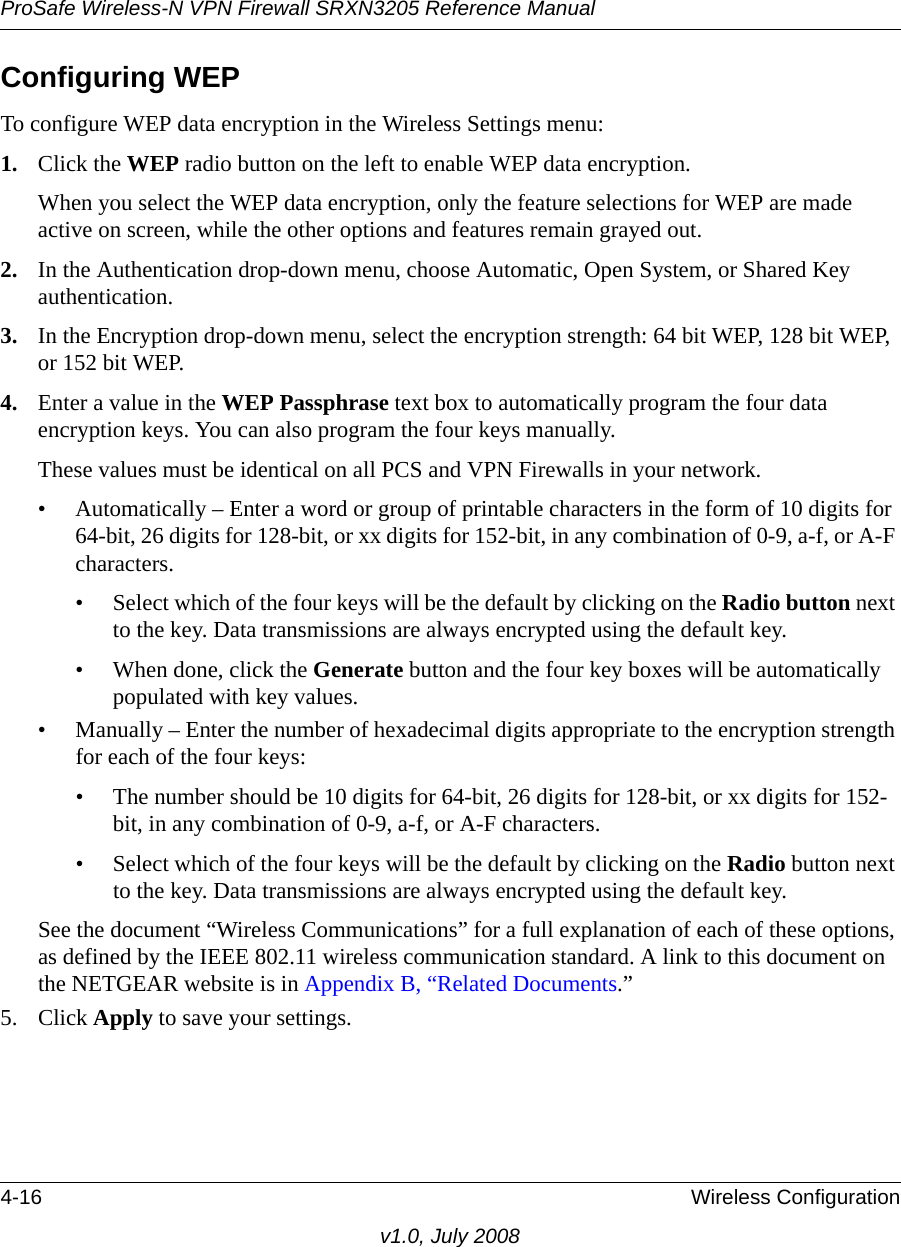
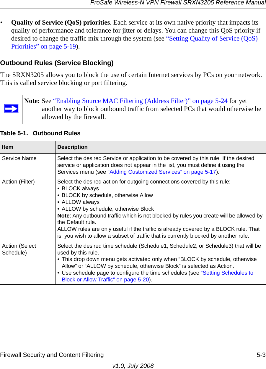
![ProSafe Wireless-N VPN Firewall SRXN3205 Reference Manual6-22 Virtual Private Networking Using IPsecv1.0, July 2008a. Under Security Policy, Phase 1 Negotiation Mode, check the Aggressive Mode radio button.b. Check the Enable Perfect Forward Secrecy (PFS) radio button, and choose the Diffie-Hellman Group 2 from the PFS Key Group pull-down menu.c. Enable Replay Detection should be checked.4. Click on Authentication (Phase 1) on the left-side of the menu and choose Proposal 1. Enter the Authentication values to match those in the firewall ModeConfig Record menu.5. Click on Key Exchange (Phase 2) on the left-side of the menu and choose Proposal 1. Enter the values to match your configuration of the firewall ModeConfig Record menu. (The SA Lifetime can be longer, such as 8 hours [28800 seconds]6. Click the Save icon to save the Security Policy and close the VPN ProSafe VPN client.To test the connection:1. Right-click on the VPN client icon in the Windows toolbar and click Connect. The connection policy you configured will appear; in this case “My Connections\modecfg_test”.2. Click on the connection. Within 30 seconds the message “Successfully connected to MyConnections/modecfg_test is displayed and the VPN client icon in the toolbar will read “On”.3. From the client PC, ping a computer on the firewall LAN.Extended Authentication (XAUTH) ConfigurationWhen connecting many VPN clients to a firewall, an administrator may want a unique user authentication method beyond relying on a single common preshared key for all clients. Although the administrator could configure a unique VPN policy for each user, it is more convenient for the firewall to authenticate users from a stored list of user accounts. XAUTH provides the mechanism for requesting individual authentication information from the user, and a local User Database or an external authentication server, such as a RADIUS server, provides a method for storing the authentication information centrally in the local network. XAUTH can be enabled when adding or editing an IKE Policy. Two types of XAUTH are available:•Edge Device. If this is selected, the firewall is used as a VPN concentrator where one or more gateway tunnels terminate. If this option is chosen, you must specify the authentication type to be used in verifying credentials of the remote VPN gateways: User Database, RADIUS-PAP, or RADIUS-CHAP.](https://usermanual.wiki/Netgear-orporated/08200084.Manual-part-1/User-Guide-988502-Page-141.png)