Netgear orporated 09400126 WIRELESS CABLE MODEM User Manual
Netgear Incorporated WIRELESS CABLE MODEM
UserManual.wiki
>
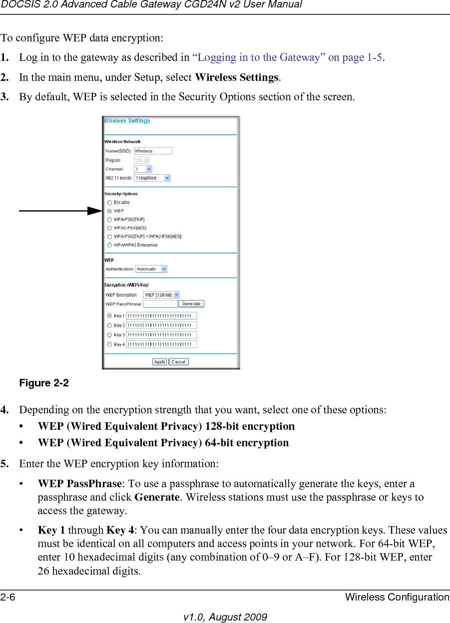
Netgear orporated
>
09400126 User Manual
Users Manual
Navigation menu
Upload a User Manual
Namespaces
Wiki Guide
HTML
PDF
Info
Views
User Manual
Discussion / Help
Navigation

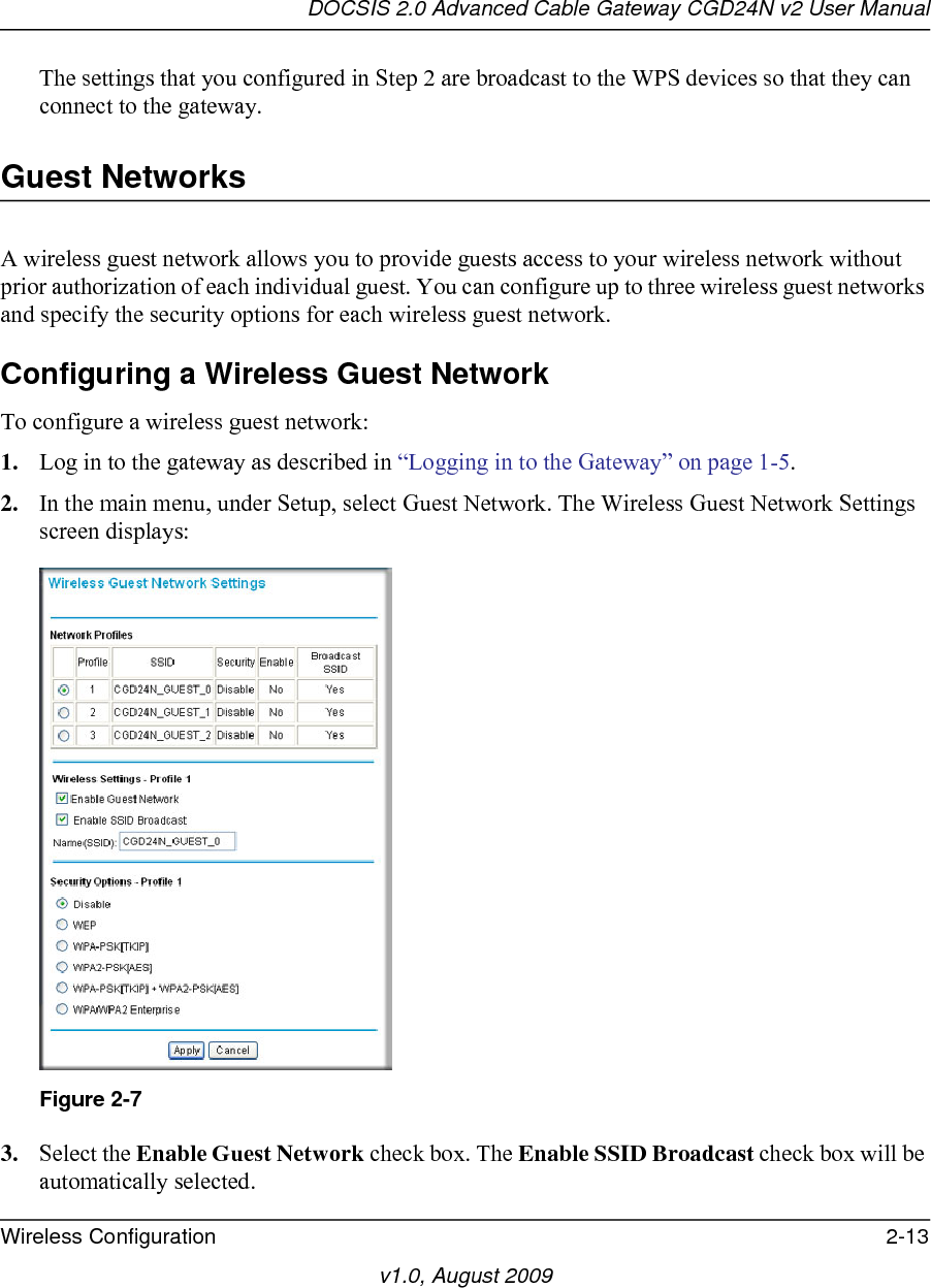
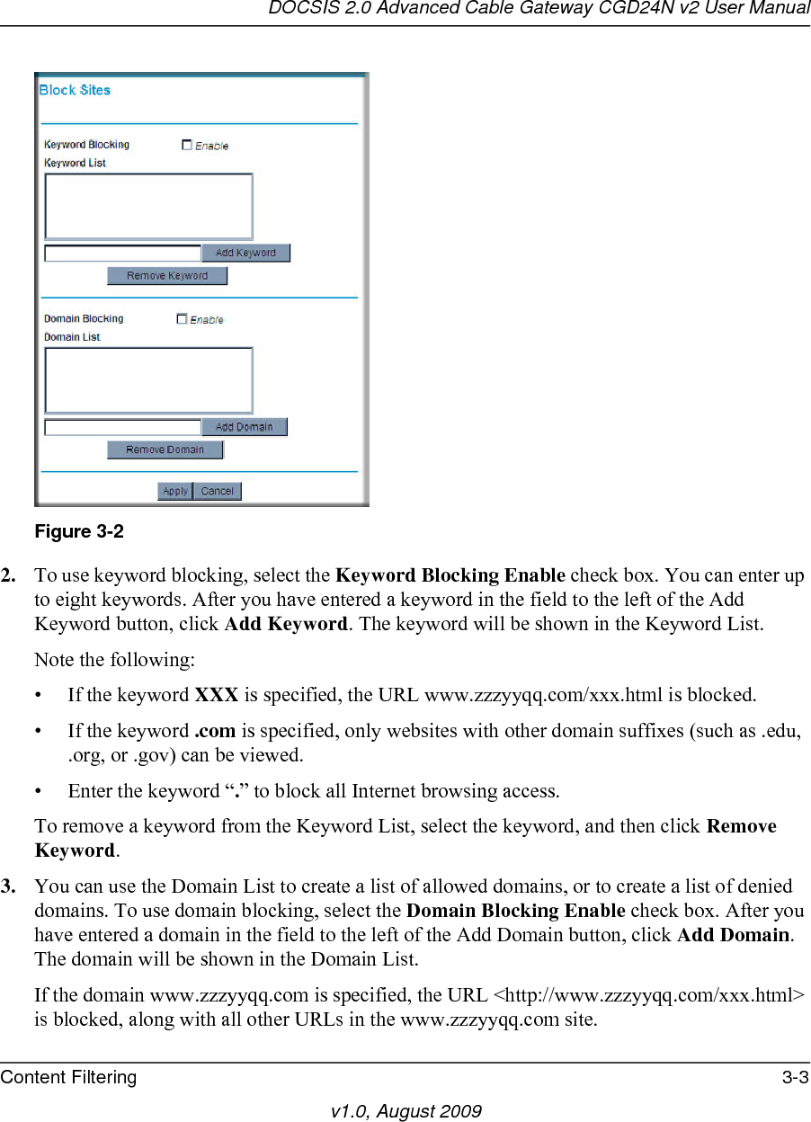
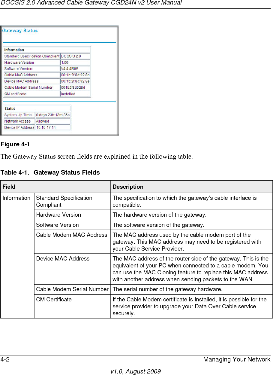
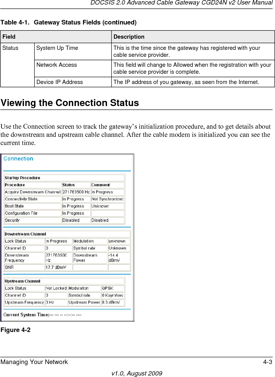
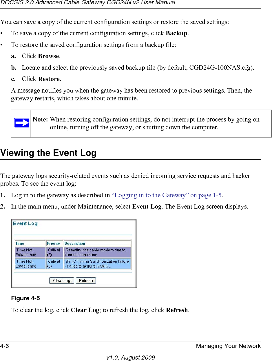
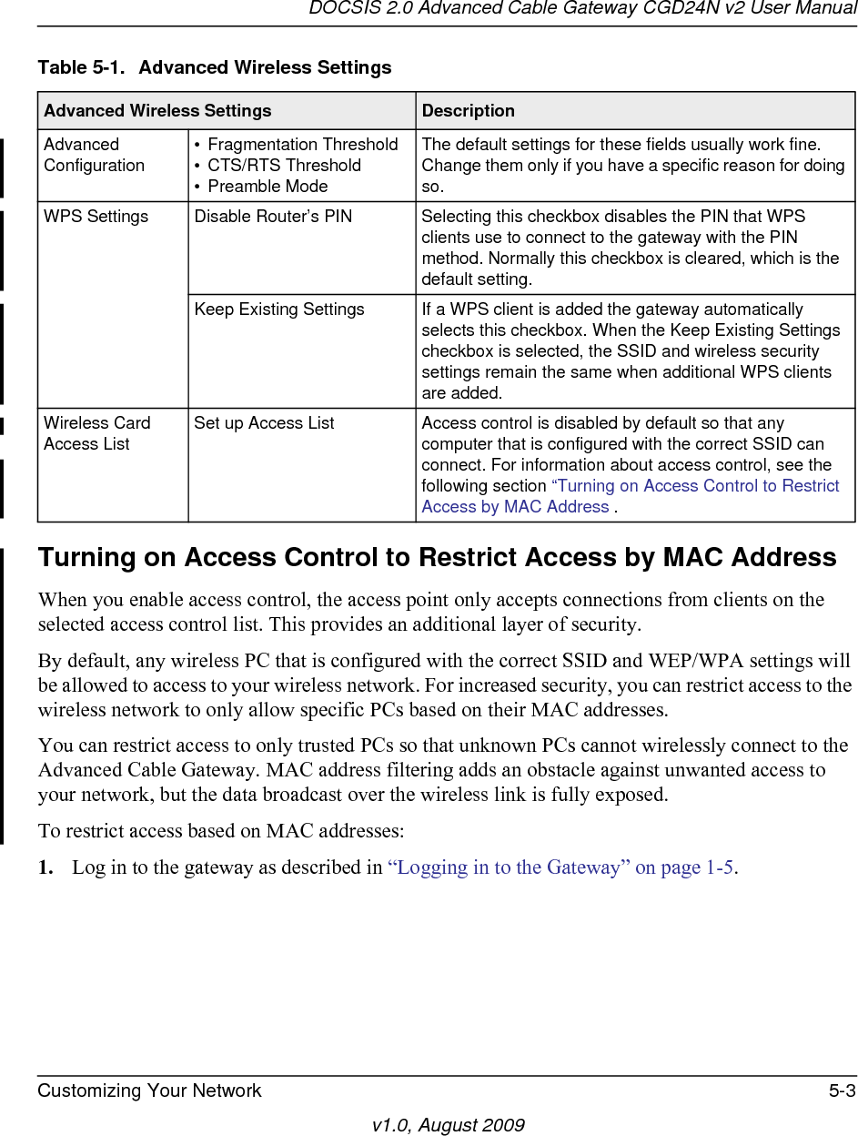
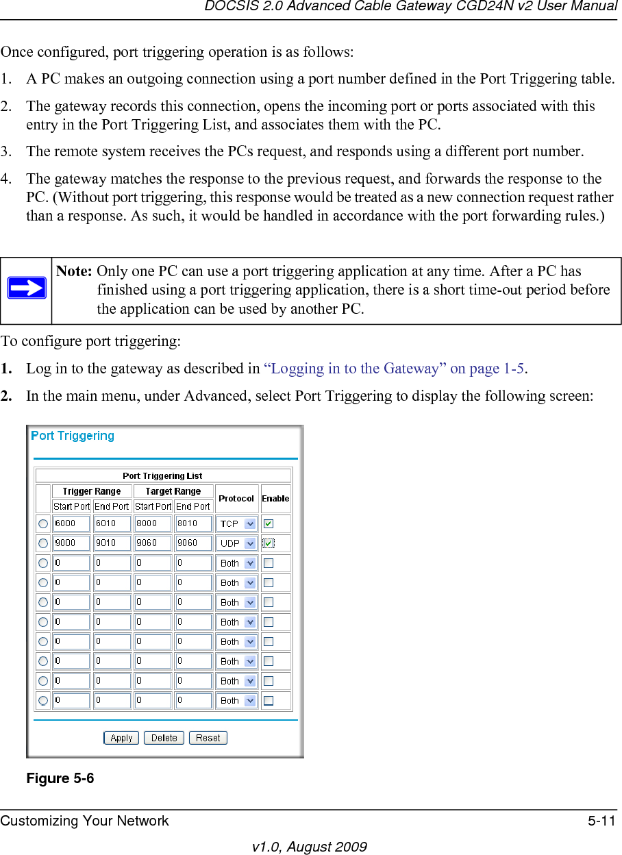
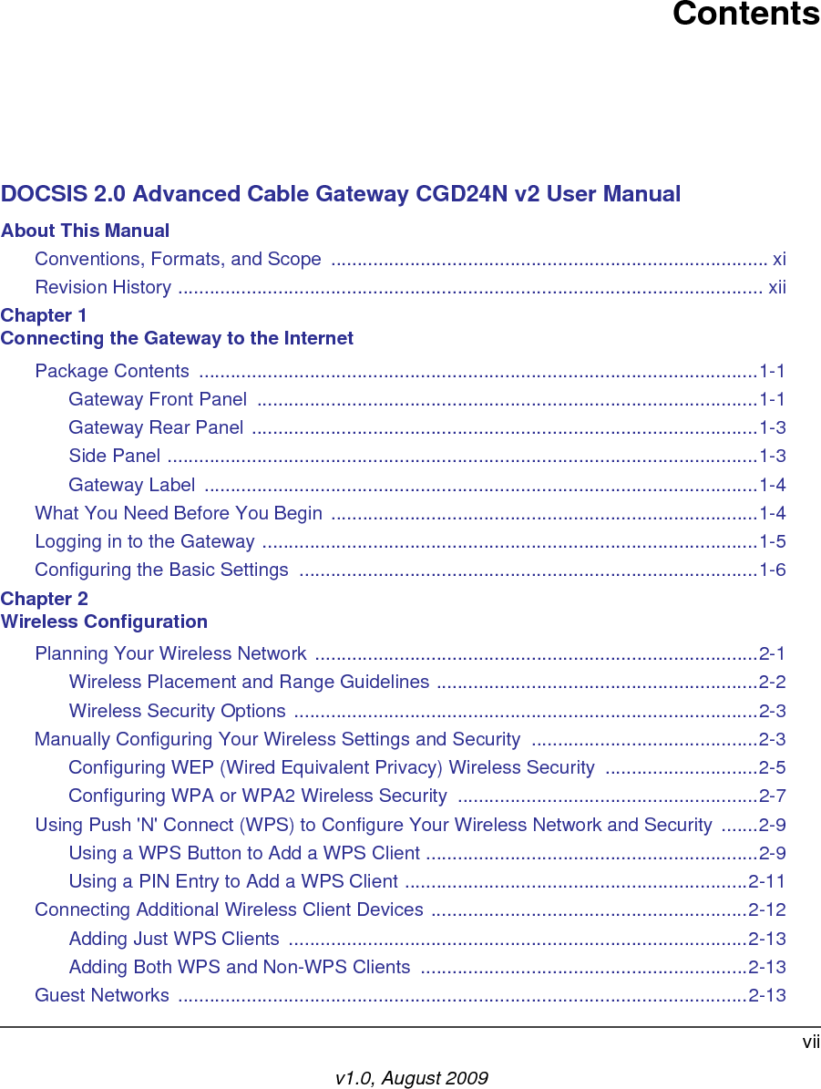
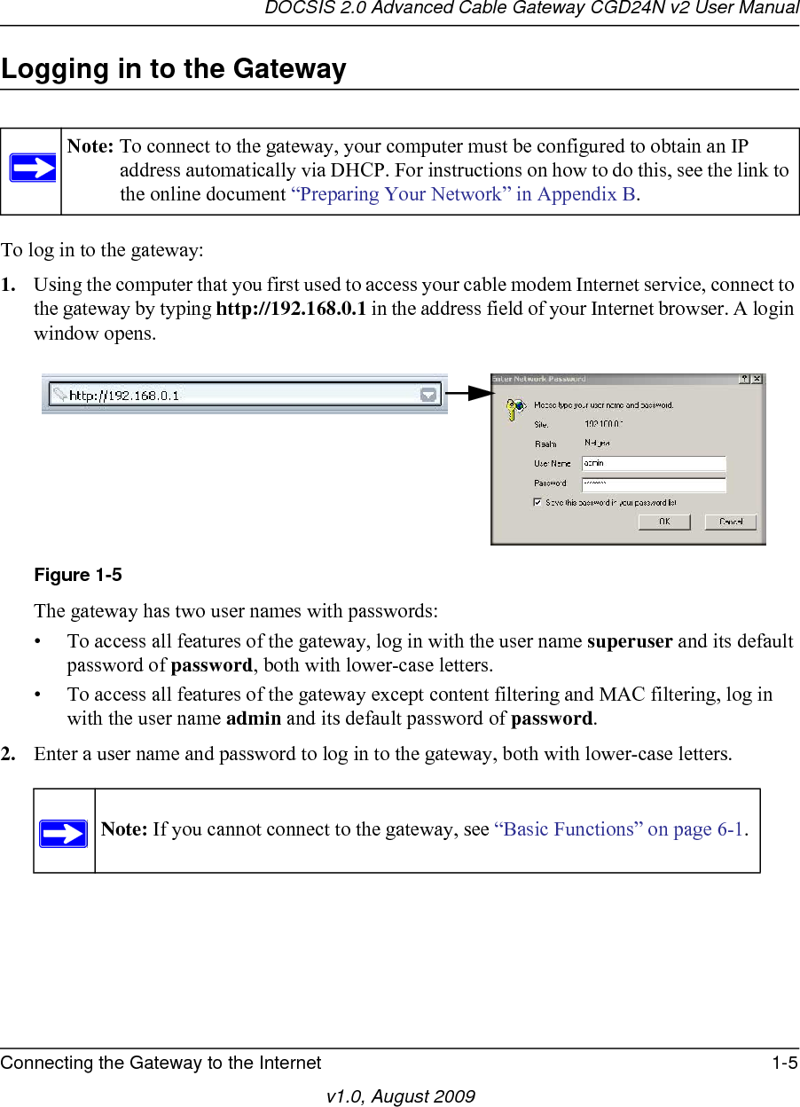
![v1.0, August 2009iiiRegulatory Compliance InformationThis section includes user requirements for operating this product in accordance with National laws for usage of radio spectrum and operation of radio devices. Failure of the end-user to comply with the applicable requirements may result in unlawful operation and adverse action against the end-user by the applicable National regulatory authority.This product's firmware limits operation to only the channels allowed in a particular Region or Country. Therefore, all options described in this user's guide may not be available in your version of the product.Europe – EU Declaration of ConformityMarking by the above symbol indicates compliance with the Essential Requirements of the R&TTE Directive of the European Union (1999/5/EC). This equipment meets the following conformance standards:EN300 328, EN301 489-17, EN60950Europe – Declaration of Conformity in Languages of the European CommunityCesky [Czech] NETGEAR Inc. tímto prohlašuje, že tento Radiolan je ve shode se základními požadavky a dalšími príslušnými ustanoveními smernice 1999/5/ES.Dansk [Danish] Undertegnede NETGEAR Inc. erklærer herved, at følgende udstyr Radiolan overholder de væsentlige krav og øvrige relevante krav i direktiv 1999/5/EF.Deutsch [German] Hiermit erklärt NETGEAR Inc., dass sich das Gerät Radiolan in Übereinstimmung mit den grundlegenden Anforderungen und den übrigen einschlägigen Bestimmungen der Richtlinie 1999/5/EG befindet.Eesti [Estonian] Käesolevaga kinnitab NETGEAR Inc. seadme Radiolan vastavust direktiivi 1999/5/EÜ põhinõuetele ja nimetatud direktiivist tulenevatele teistele asjakohastele sätetele.English Hereby, NETGEAR Inc., declares that this Radiolan is in compliance with the essential requirements and other relevant provisions of Directive 1999/5/EC.Español [Spanish] Por medio de la presente NETGEAR Inc. declara que el Radiolan cumple con los requisitos esenciales y cualesquiera otras disposiciones aplicables o exigibles de la Directiva 1999/5/CE.Ελληνική [Greek]ΜΕ ΤΗΝ ΠΑΡΟΥΣΑ NETGEAR Inc. ΔΗΛΩΝΕΙ ΟΤΙ Radiolan ΣΥΜΜΟΡΦΩΝΕΤΑΙ ΠΡΟΣ ΤΙΣ ΟΥΣΙΩΔΕΙΣ ΑΠΑΙΤΗΣΕΙΣ ΚΑΙ ΤΙΣ ΛΟΙΠΕΣ ΣΧΕΤΙΚΕΣ ΔΙΑΤΑΞΕΙΣ ΤΗΣ ΟΔΗΓΙΑΣ 1999/5/ΕΚ.Français [French] Par la présente NETGEAR Inc. déclare que l'appareil Radiolan est conforme aux exigences essentielles et aux autres dispositions pertinentes de la directive 1999/5/CE.Italiano [Italian] Con la presente NETGEAR Inc. dichiara che questo Radiolan è conforme ai requisiti essenziali ed alle altre disposizioni pertinenti stabilite dalla direttiva 1999/5/CE.Latviski [Latvian] Ar šo NETGEAR Inc. deklarē, ka Radiolan atbilst Direktīvas 1999/5/EK būtiskajām prasībām un citiem ar to saistītajiem noteikumiem.](https://usermanual.wiki/Netgear-orporated/09400126/User-Guide-1235892-Page-3.png)
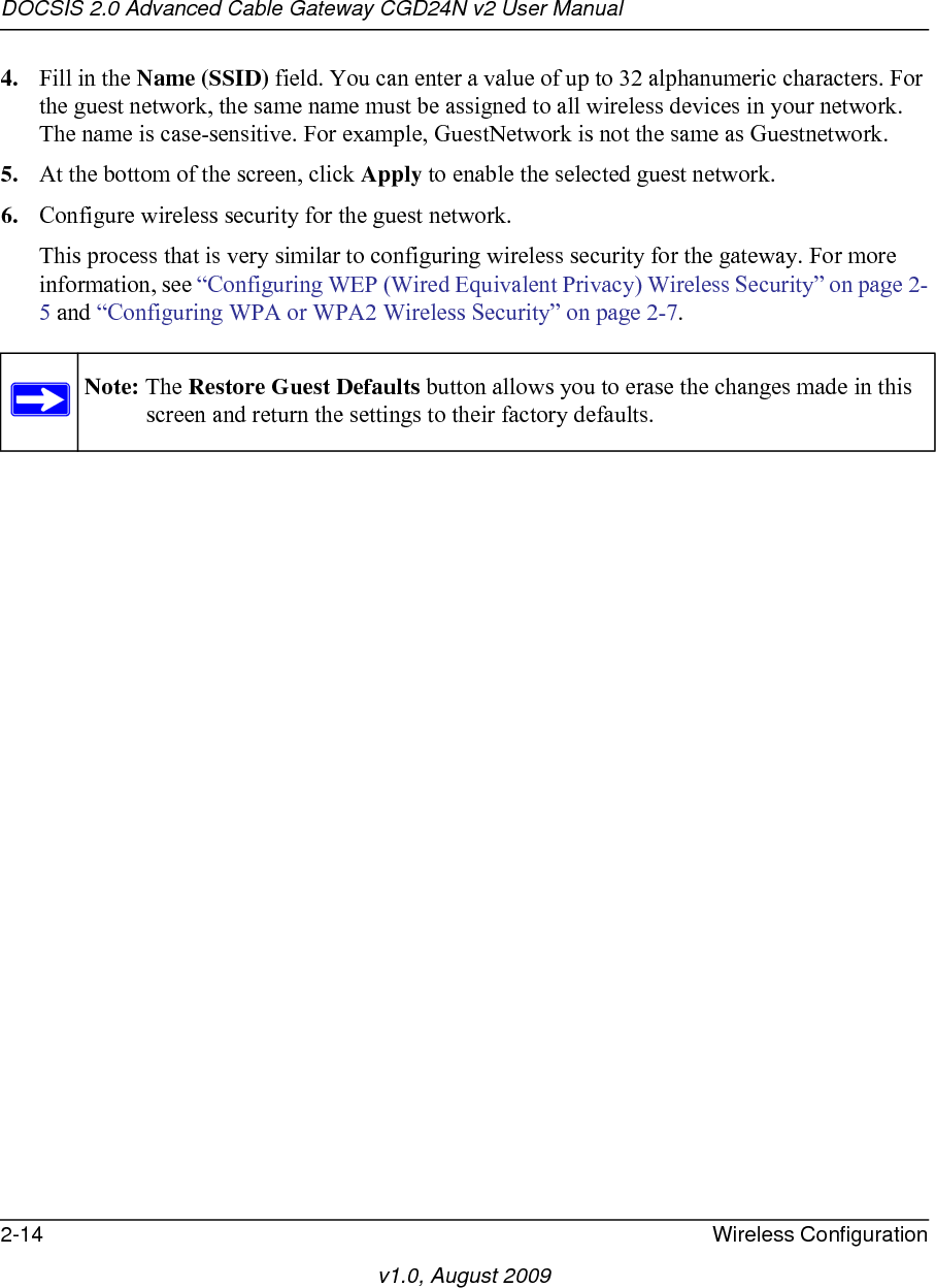
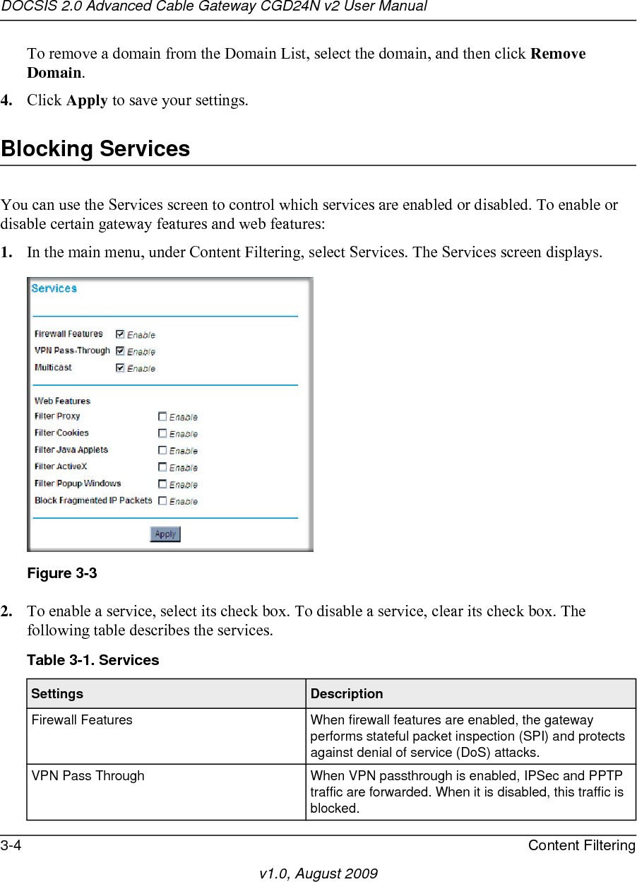
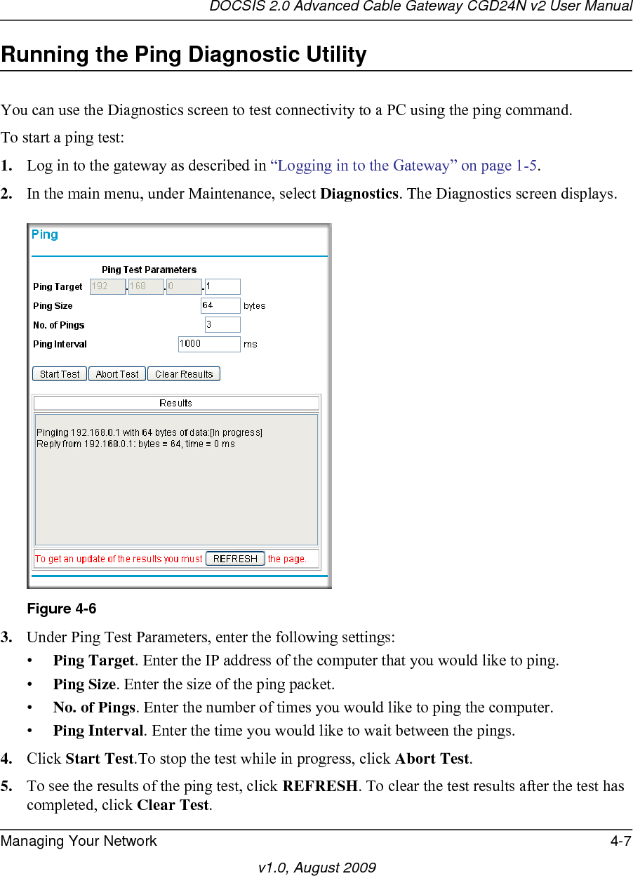
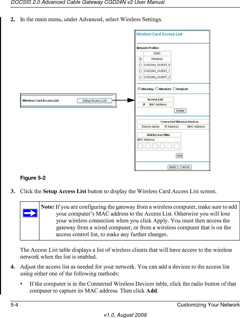
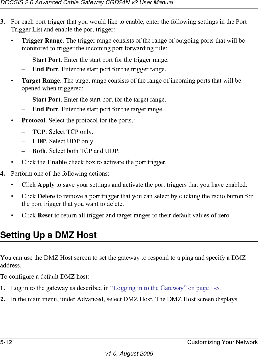
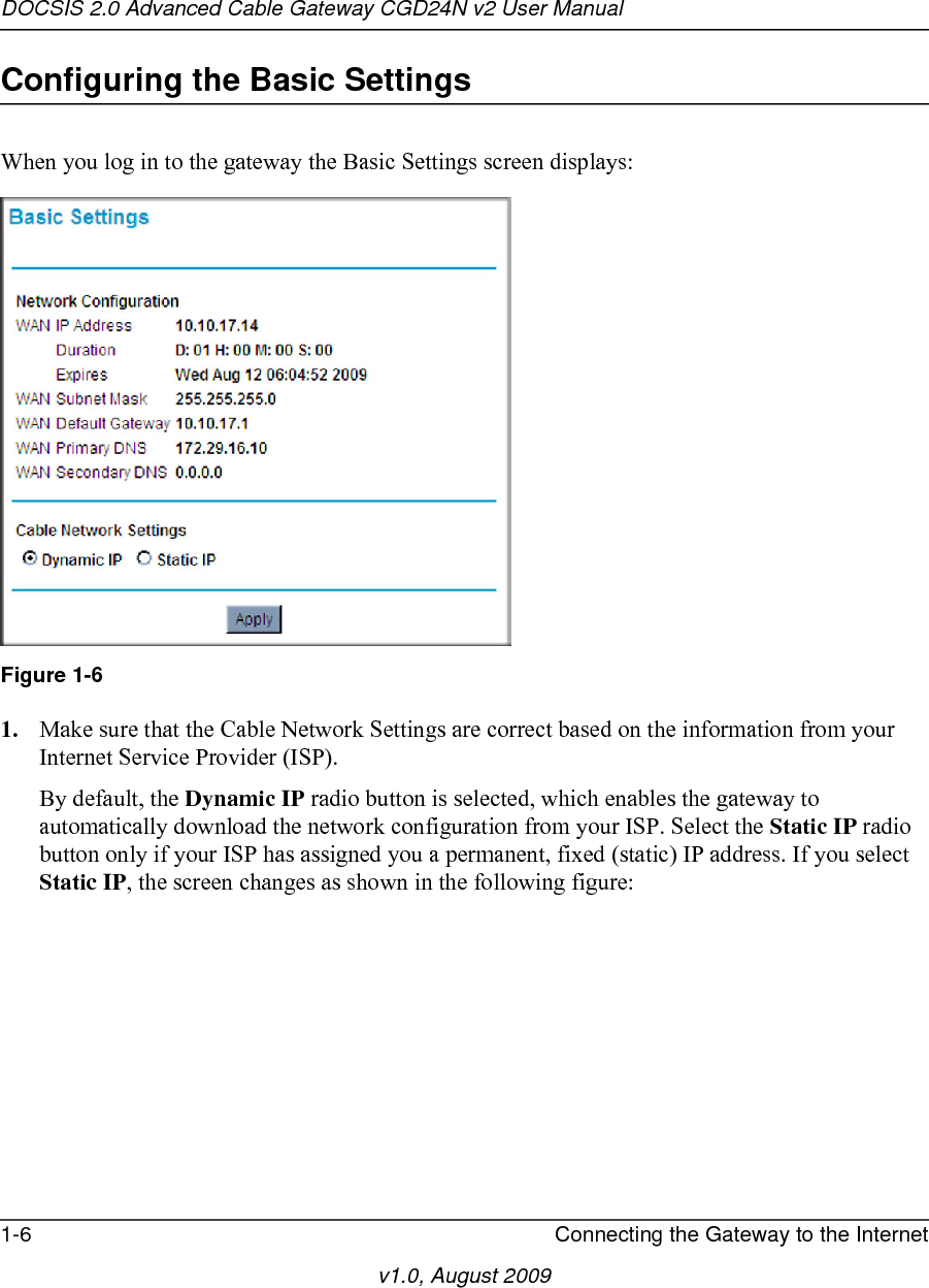
![v1.0, August 2009ivFCC Requirements for Operation in the United States FCC Information to UserThis product does not contain any user serviceable components and is to be used with approved antennas only. Any product changes or modifications will invalidate all applicable regulatory certifications and approvalsFCC Guidelines for Human ExposureThis equipment complies with FCC radiation exposure limits set forth for an uncontrolled environment. This equipment should be installed and operated with minimum distance of 20 cm between the radiator and your body. This transmitter must not be co-located or operating in conjunction with any other antenna or transmitter. Lietuvių [Lithuanian] Šiuo NETGEAR Inc. deklaruoja, kad šis Radiolan atitinka esminius reikalavimus ir kitas 1999/5/EB Direktyvos nuostatas.Nederlands [Dutch] Hierbij verklaart NETGEAR Inc. dat het toestel Radiolan in overeenstemming is met de essentiële eisen en de andere relevante bepalingen van richtlijn 1999/5/EG.Malti [Maltese] Hawnhekk, NETGEAR Inc., jiddikjara li dan Radiolan jikkonforma mal-htigijiet essenzjali u ma provvedimenti ohrajn relevanti li hemm fid-Dirrettiva 1999/5/EC.Magyar [Hungarian] Alulírott, NETGEAR Inc. nyilatkozom, hogy a Radiolan megfelel a vonatkozó alapvetõ követelményeknek és az 1999/5/EC irányelv egyéb elõírásainak.Polski [Polish] Niniejszym NETGEAR Inc. oświadcza, że Radiolan jest zgodny z zasadniczymi wymogami oraz pozostałymi stosownymi postanowieniami Dyrektywy 1999/5/EC.Português [Portuguese] NETGEAR Inc. declara que este Radiolan está conforme com os requisitos essenciais e outras disposições da Directiva 1999/5/CE.Slovensko [Slovenian] NETGEAR Inc. izjavlja, da je ta Radiolan v skladu z bistvenimi zahtevami in ostalimi relevantnimi določili direktive 1999/5/ES.Slovensky [Slovak] NETGEAR Inc. týmto vyhlasuje, _e Radiolan spĺňa základné po_iadavky a všetky príslušné ustanovenia Smernice 1999/5/ES.Suomi [Finnish] NETGEAR Inc. vakuuttaa täten että Radiolan tyyppinen laite on direktiivin 1999/5/EY oleellisten vaatimusten ja sitä koskevien direktiivin muiden ehtojen mukainen.Svenska [Swedish] Härmed intygar NETGEAR Inc. att denna Radiolan står I överensstämmelse med de väsentliga egenskapskrav och övriga relevanta bestämmelser som framgår av direktiv 1999/5/EG.Íslenska [Icelandic] Hér með lýsir NETGEAR Inc. yfir því að Radiolan er í samræmi við grunnkröfur og aðrar kröfur, sem gerðar eru í tilskipun 1999/5/EC.Norsk [Norwegian] NETGEAR Inc. erklærer herved at utstyret Radiolan er i samsvar med de grunnleggende krav og øvrige relevante krav i direktiv 1999/5/EF.](https://usermanual.wiki/Netgear-orporated/09400126/User-Guide-1235892-Page-4.png)

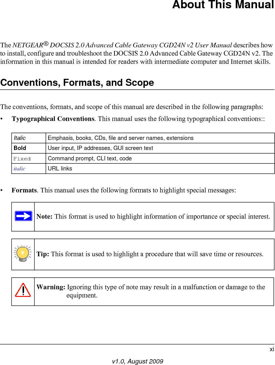
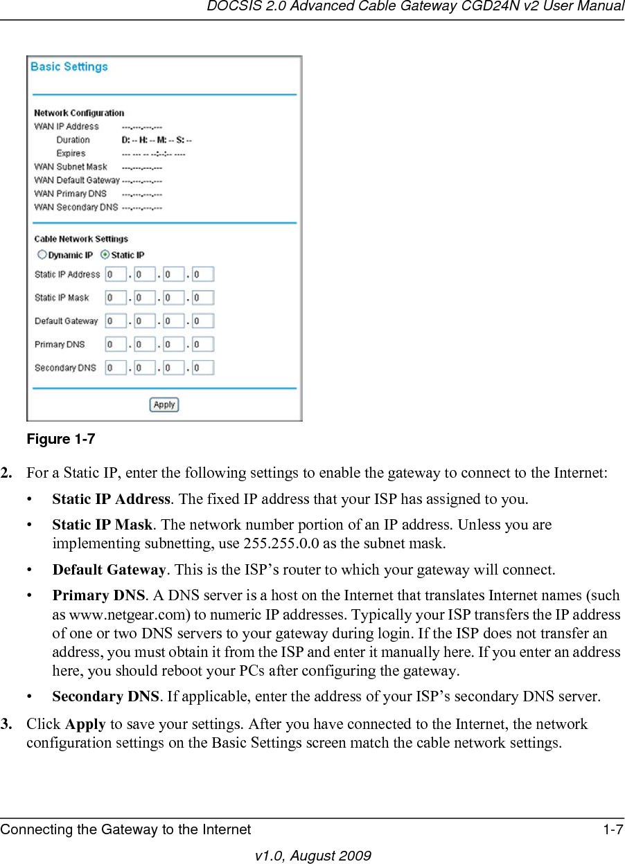

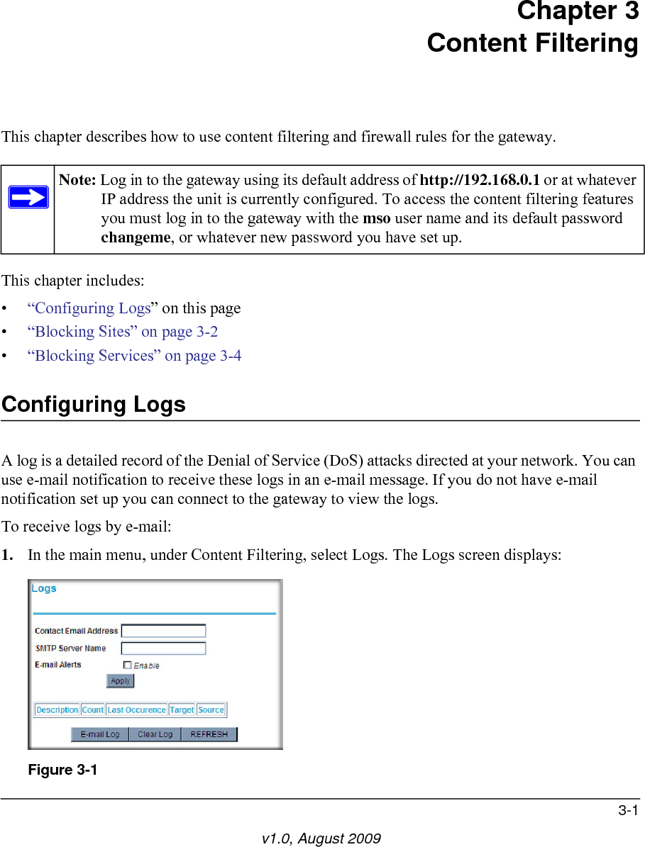
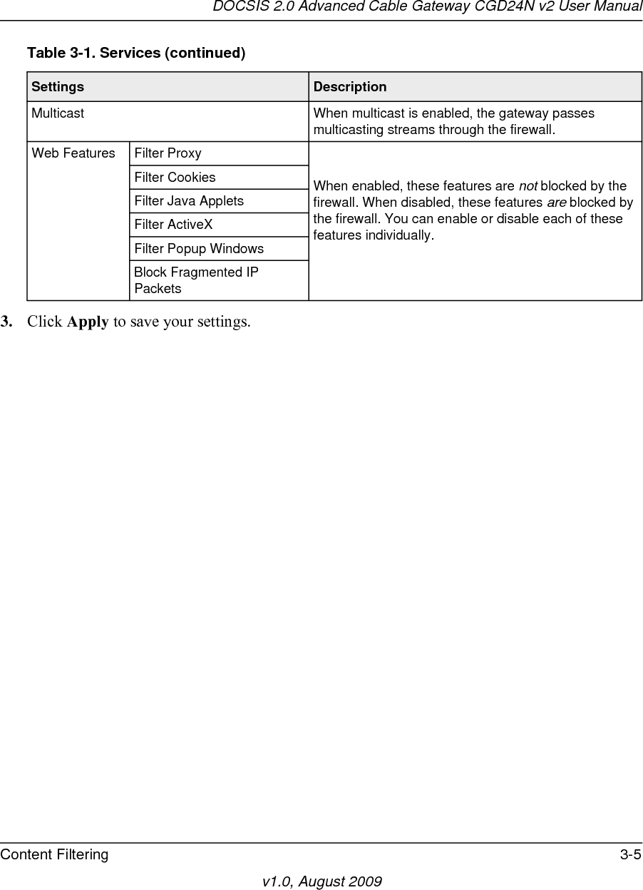
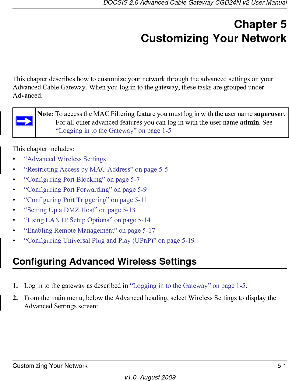
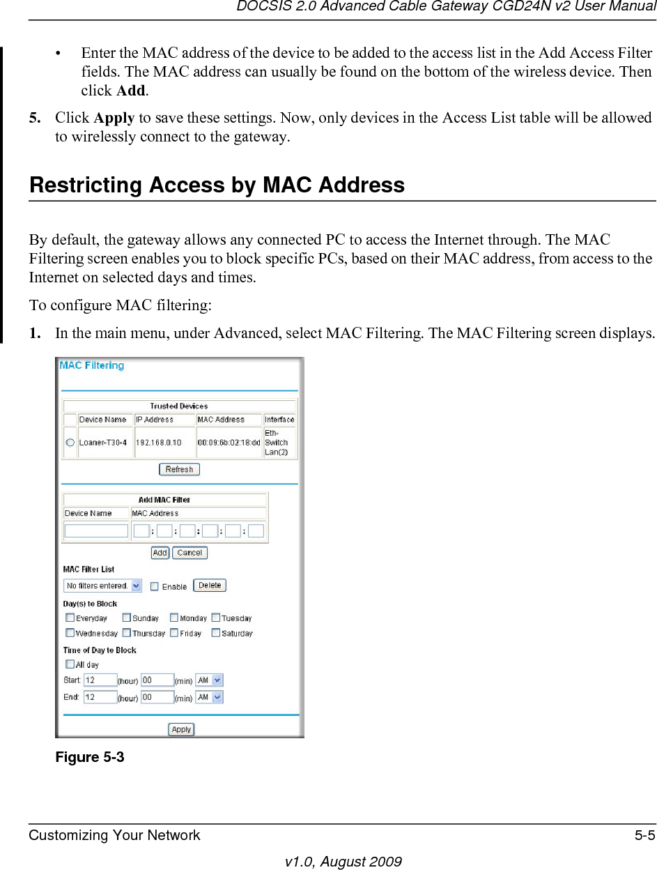
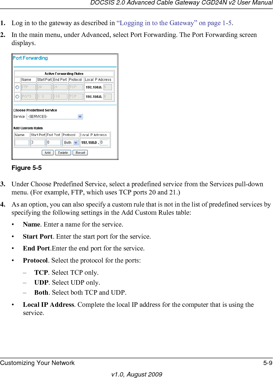
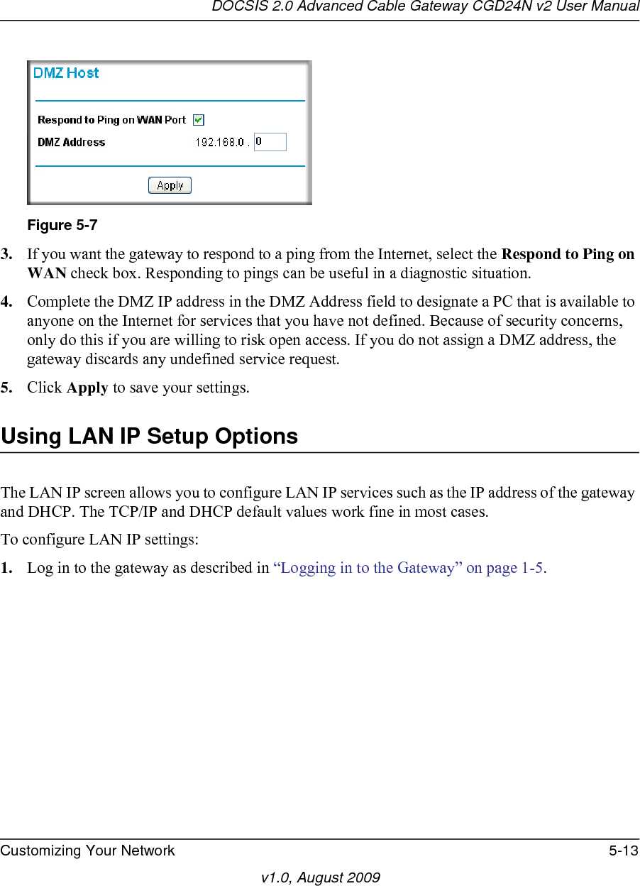
![DOCSIS 2.0 Advanced Cable Gateway CGD24N v2 User ManualWireless Configuration 2-7v1.0, August 2009• Select which of the four keys will be the default. Data transmissions are always encrypted using the default key. The other keys can only be used to decrypt received data. The four entries are disabled if WPA-PSK or WPA authentication is selected.6. Click Apply to save your settings.Configuring WPA or WPA2 Wireless SecurityTo configure WPA in the gateway:1. Log in to the gateway as described in “Logging in to the Gateway” on page 1-5.2. In the main menu, under Setup, select Wireless Settings.3. Select a WPA setting:•WPA-PSK [TKIP]. TKIP encryption type and a pre-shared key passphrase.•WPA2-PSK [AES]. AES encryption type and a pre-shared key passphrase.Note: Newer wireless adapters support WPA. Windows XP and Windows 2000 with Service Pack 3 or above include the client software that supports WPA. The wireless adapter hardware and driver must also support WPA. Consult the product documentation for your wireless adapter and WPA client software for instructions on configuring WPA settings.Figure 2-3](https://usermanual.wiki/Netgear-orporated/09400126/User-Guide-1235892-Page-27.png)
![DOCSIS 2.0 Advanced Cable Gateway CGD24N v2 User Manual2-8 Wireless Configurationv1.0, August 2009•WPA-PSK [TKIP] + WPA2-PSK [AES]. •WPA/WPA2 Enterprise. TKIP encryption type with authentication from a RADIUS server.The content displayed in the screen depends on the WPA setting that you selected. 4. Depending on the WPA settings that you select, enter the required information:• For WPA-PSK or WPA2-PSK, enter the pre-shared key, which is a passphrase between 8 and 63 characters.• For WPA, enter the settings for the RADIUS Server:–Primary Radius Server IP Address. The IP address of the RADIUS server. The default is 0.0.0.0.–Radius Port. Port number of the RADIUS server. The default is 1812.–Shared Key. This is shared between the wireless access point and the RADIUS server while authenticating the supplicant.5. Click Apply to save your settings.Using Push 'N' Connect (WPS) to Configure Your Wireless Network and SecurityIf your wireless clients support Wi-Fi Protected Setup (WPS), you can use this feature to configure the gateway’s SSID and security settings and, at the same time, connect the wireless client securely and easily to the gateway. Look for the symbol on your client device (computers that will connect wirelessly to the gateway are clients). WPS automatically configures the network name (SSID) and wireless security settings for the gateway (if the gateway is in its default state) and broadcasts these settings to the wireless client.Some considerations regarding WPS are:• WPS supports only WPA-PSK and WPA2-PSK wireless security. WEP security is not supported by WPS.Note: NETGEAR’s Push 'N' Connect feature based on the Wi-Fi Protected Setup (WPS) standard (for more information, see http://www.wi-fi.org). All other Wi-Fi-certified and WPS-capable products should be compatible with NETGEAR products that implement Push 'N' Connect.](https://usermanual.wiki/Netgear-orporated/09400126/User-Guide-1235892-Page-28.png)
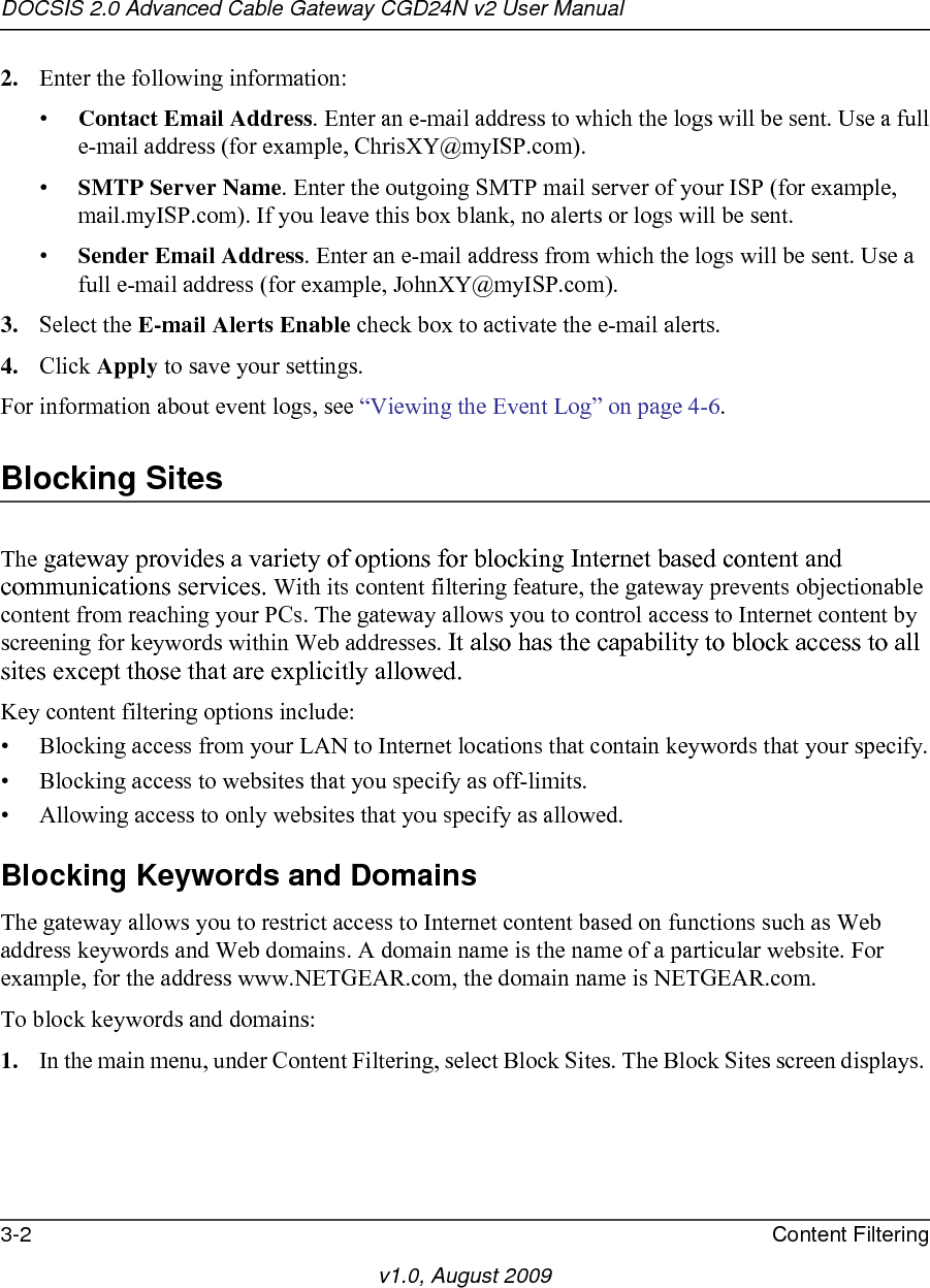
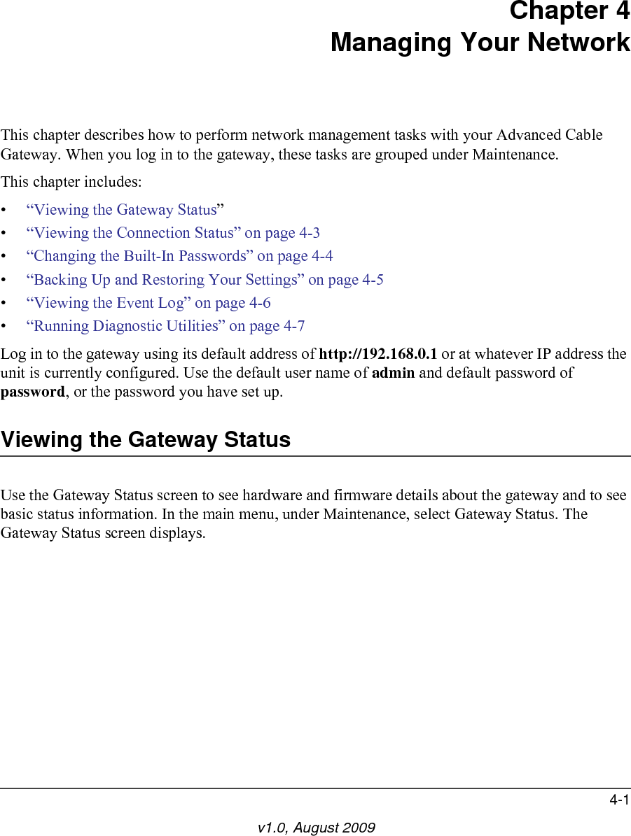
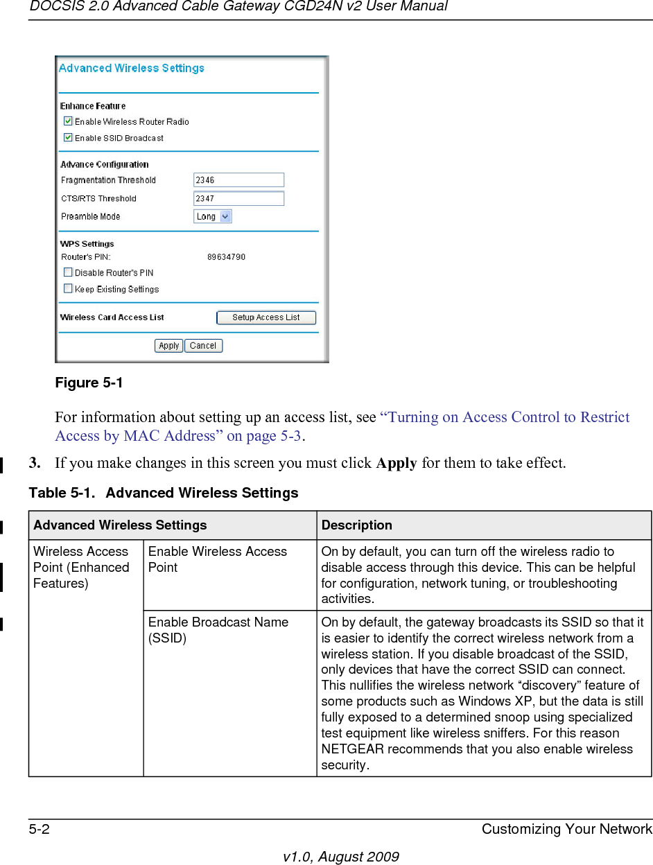
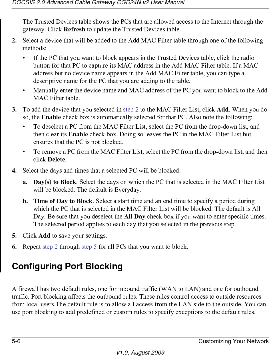
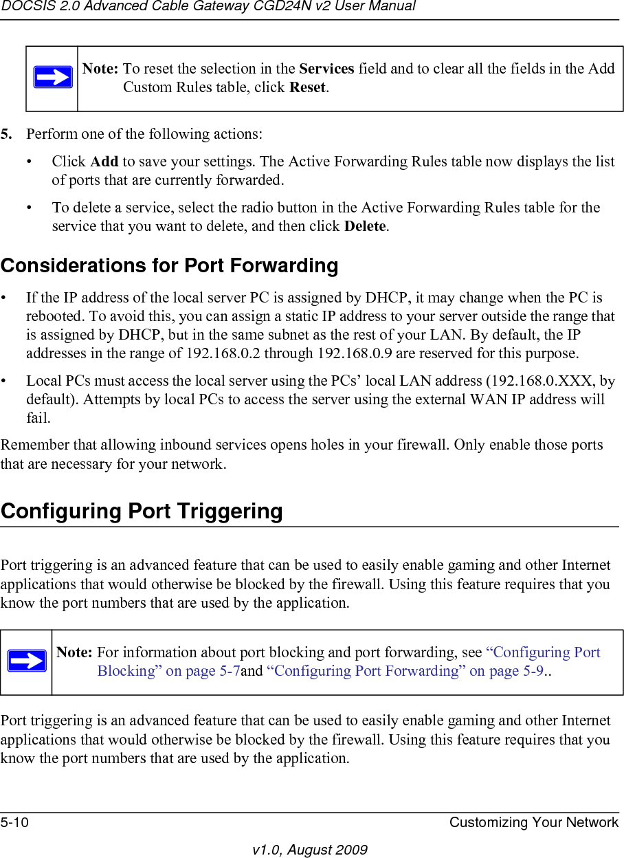
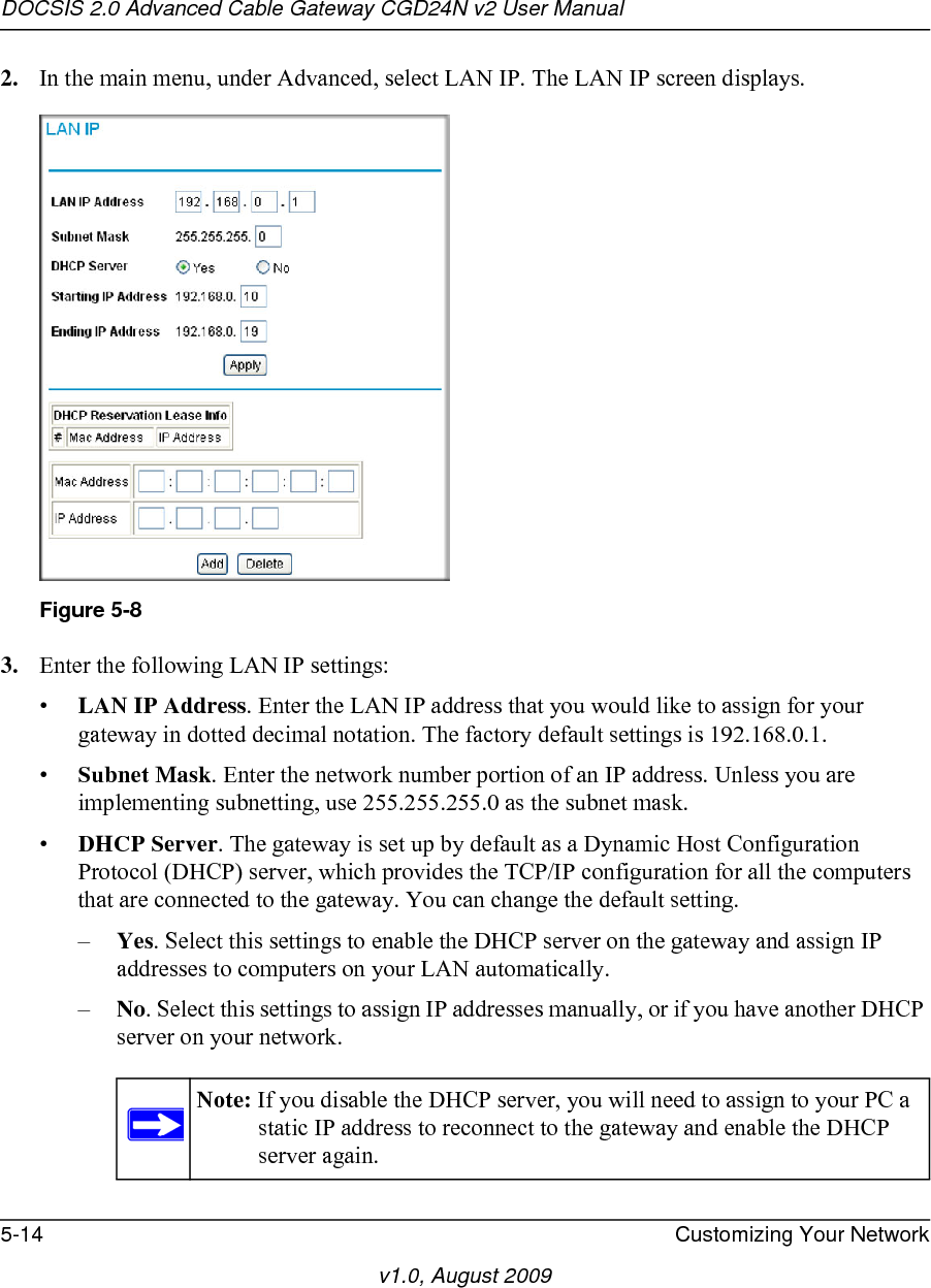
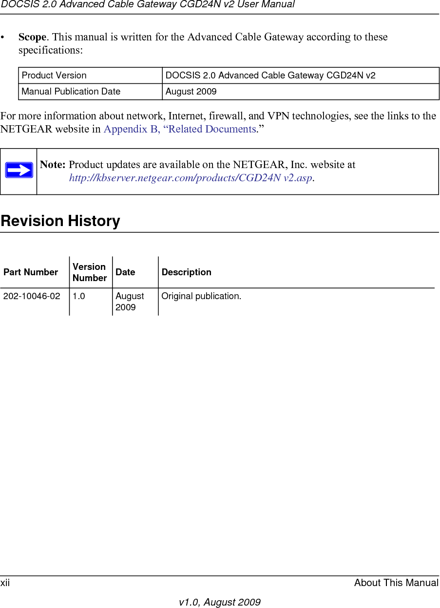
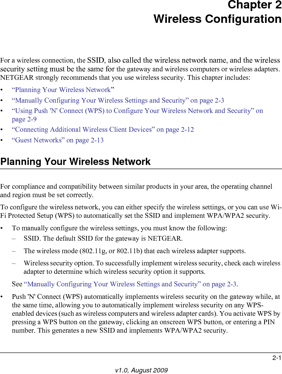
![DOCSIS 2.0 Advanced Cable Gateway CGD24N v2 User ManualWireless Configuration 2-9v1.0, August 2009• If your wireless network will include a combination of WPS capable devices and non-WPS capable devices, NETGEAR suggests that you set up your wireless network and security settings manually first, and use WPS only for adding additional WPS capable devices. See “Adding Both WPS and Non-WPS Clients” on page 2-13.A WPS client can be added using the Push Button method or the PIN method.•Using the Push Button. This is the preferred method. See the following section, “Using a WPS Button to Add a WPS Client.•Entering a PIN. For information about using the PIN method, see “Using a PIN Entry to Add a WPS Client” on page 2-11.Using a WPS Button to Add a WPS ClientAny wireless computer or wireless adapter that will connect to the gateway wirelessly is a client. The client must support a WPS PIN, and must have a WPS configuration utility, such as the NETGEAR Smart Wizard or Atheros Jumpstart.To use the gateway WPS button to add a WPS client: 1. Log in to the gateway as described in “Logging in to the Gateway” on page 1-5.2. On the main menu, select Add WPS Client and click Next. By default, Push Button is selected as the setup method.Note: By default, the gateway is configured with WEP security, which is incompatible with WPS. If WEP is configured when you add a WPS client, the gateway will change the wireless security to WPA-PSK [TIP] + WPA2-PSK [AES] when it adds the client.Figure 2-4](https://usermanual.wiki/Netgear-orporated/09400126/User-Guide-1235892-Page-29.png)
![DOCSIS 2.0 Advanced Cable Gateway CGD24N v2 User Manual2-10 Wireless Configurationv1.0, August 20093. Either push the WPS button on the side of your gateway or click the onscreen button.The screen displays the progress as the gateway tries to communicate with the client for 2 minutes:While the gateway tries to establish a connection, you can stop the process by clicking Cancel.4. Go to the client wireless computer, and run a WPS configuration utility. Follow the utility’s instructions to click a WPS button.5. Go back to the gateway screen and check the display:•Success. A connection is established. The gateway has generated an SSID, implemented WPA/WPA2 wireless security (including a PSK security password) on the gateway, and has sent this configuration to the wireless client.•Failure. No connection is detected, and no SSID or security settings are configured on the gateway.Note the new SSID and WPA/WPA2 password for the wireless network. You can view these settings in the Wireless Settings screen. See “Manually Configuring Your Wireless Settings and Security” on page 2-3.To access the Internet from any computer connected to your gateway, launch a browser such as Microsoft Internet Explorer or Mozilla Firefox. You should see the gateway’s Internet LED blink, indicating communication to the ISP.Using a PIN Entry to Add a WPS ClientAny wireless computer or wireless adapter that will connect to the gateway wirelessly is a client. The client must support a WPS PIN, and must have a WPS configuration utility, such as the NETGEAR Smart Wizard or Atheros Jumpstart.Figure 2-5Note: By default, the gateway is configured with WEP security, which is incompatible with WPS. If WEP is configured when you add a WPS client, the wireless security changes to WPA-PSK [TIP] + WPA2-PSK [AES] when the client is added.](https://usermanual.wiki/Netgear-orporated/09400126/User-Guide-1235892-Page-30.png)
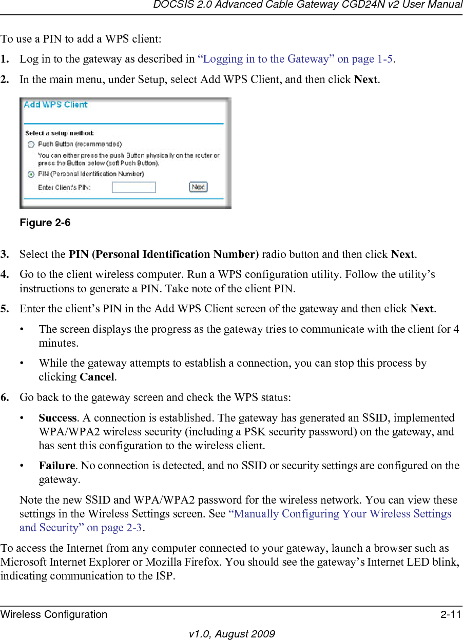
![DOCSIS 2.0 Advanced Cable Gateway CGD24N v2 User Manual2-12 Wireless Configurationv1.0, August 2009Connecting Additional Wireless Client DevicesYou can add more WPS clients to your wireless network, or you can add a combination of WPS-enabled clients and clients without WPS.Adding Just WPS ClientsTo add a wireless client device that is WPS-enabled, follow the procedures in “Using a WPS Button to Add a WPS Client” on page 2-9 or “Using a PIN Entry to Add a WPS Client” on page 2-11.Adding Both WPS and Non-WPS ClientsFor non-WPS clients, you cannot use the WPS setup procedures to add them to the wireless network. You must record, and then manually enter your security settings (see “Manually Configuring Your Wireless Settings and Security” on page 2-3).To connect a combination of non-WPS enabled and WPS-Enabled clients to the gateway:1. Restore the gateway to its factory default settings (press the Restore Factory Settings button on the rear panel of the gateway for 5 seconds).When the factory settings are restored, all existing wireless clients are disassociated and disconnected from the gateway.2. Configure the network name (SSID), select the WPA/PSK [TKIP] + WPA2/PSK[AES] radio button on the Wireless Settings screen (see “Manually Configuring Your Wireless Settings and Security” on page 2-3). and click Apply. On the WPA/PSK + WPA2/PSK screen, select a passphrase and click Apply. Record this information to add additional clients.3. For the non-WPS devices that you want to connect, open the networking utility and follow the utility’s instructions to enter the security settings that you selected in Step 2 (the SSID, WPA/PSK + WPA2/PSK security method, and passphrase).4. For the WPS devices that you want to connect, follow the procedure “Using a WPS Button to Add a WPS Client” on page 2-9 or “Using a PIN Entry to Add a WPS Client” on page 2-11.Note: If no WPS-capable client devices are located during the 2-minute timeframe, the SSID will not be changed and no security will be implemented on the gateway.](https://usermanual.wiki/Netgear-orporated/09400126/User-Guide-1235892-Page-32.png)