Netgear orporated 10300138 11n wireless AP User Manual
Netgear Incorporated 11n wireless AP
UserManual.wiki
>
Netgear orporated
>
10300138 User Manual
User Manual
Navigation menu
Upload a User Manual
Namespaces
Wiki Guide
HTML
PDF
Info
Views
User Manual
Discussion / Help
Navigation

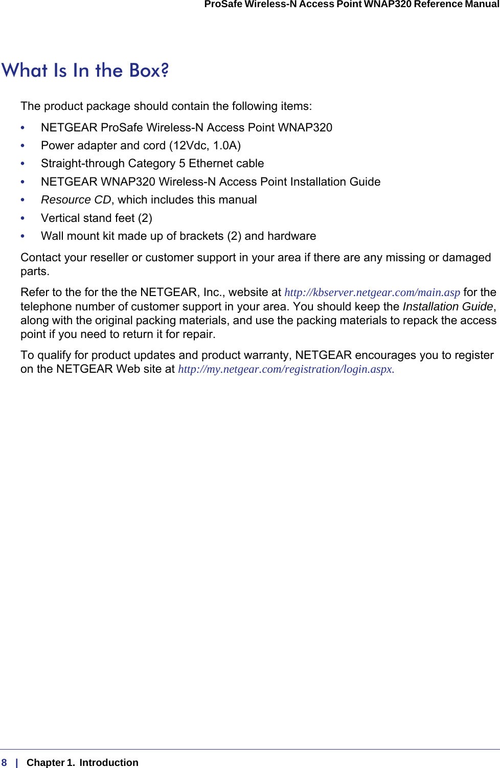
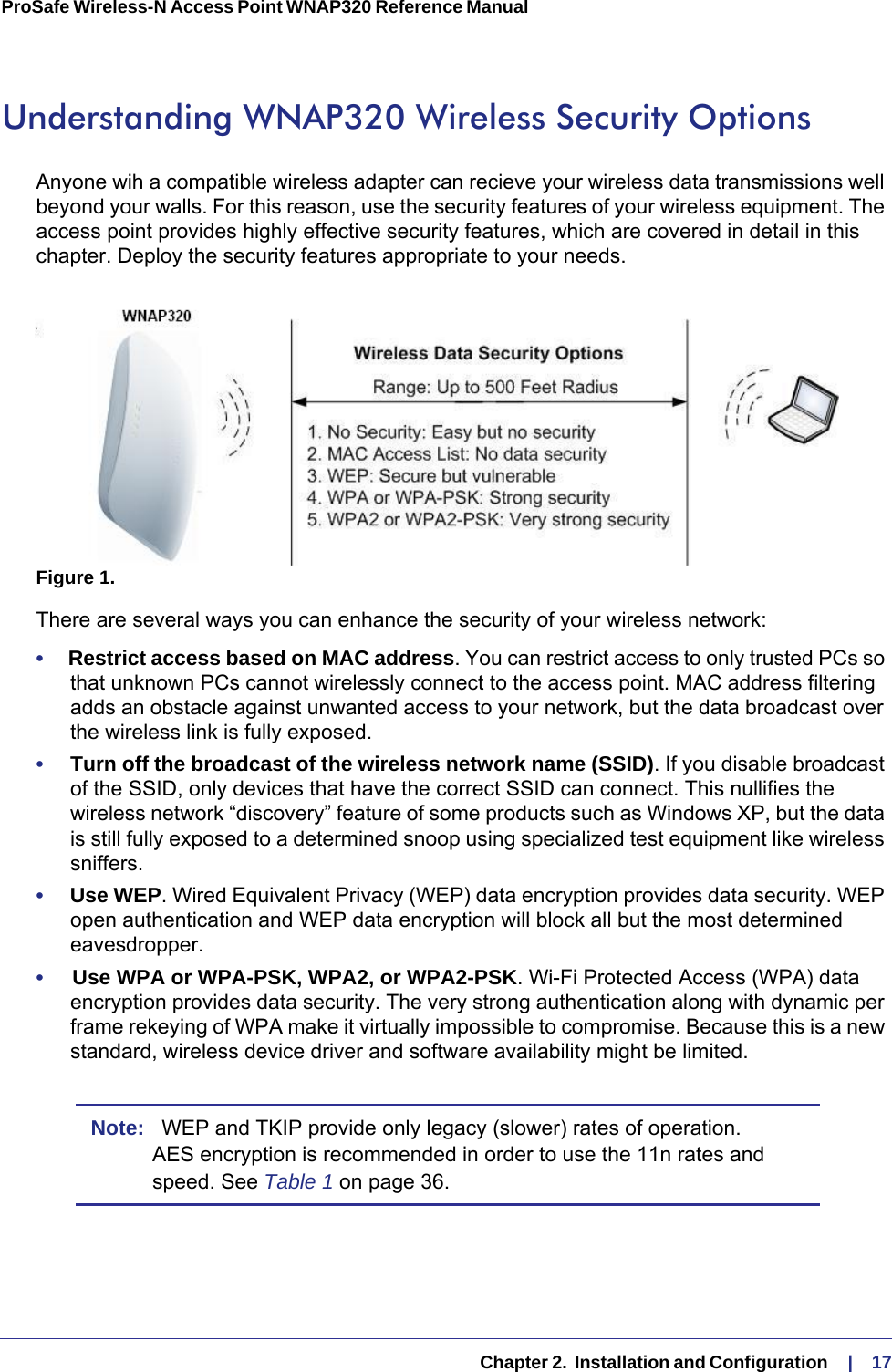
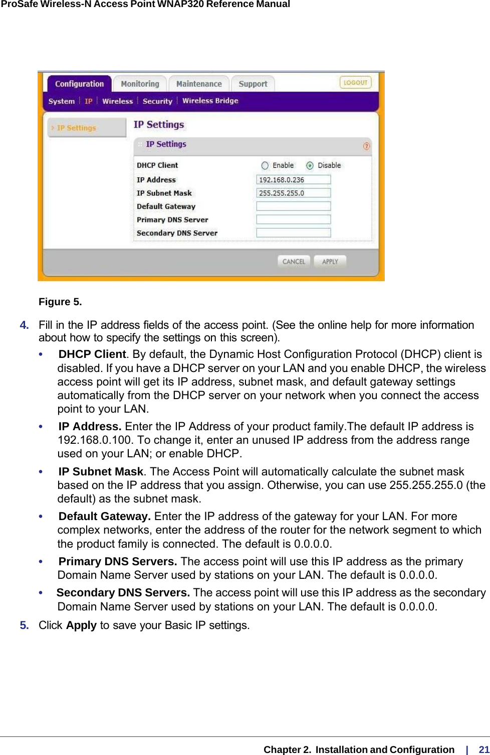
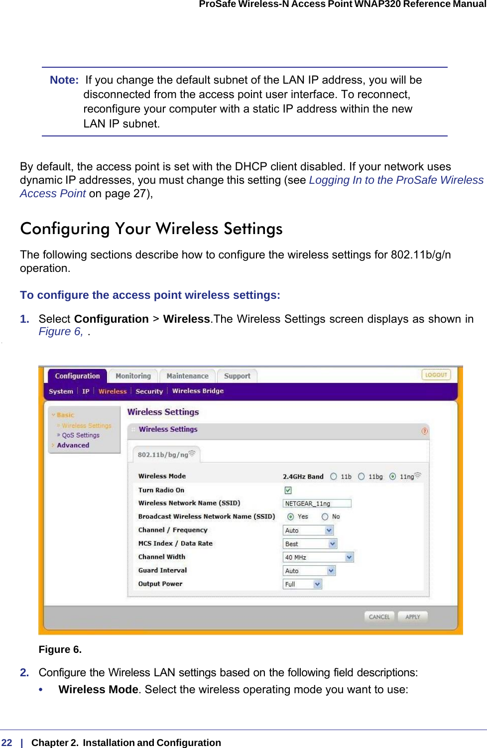
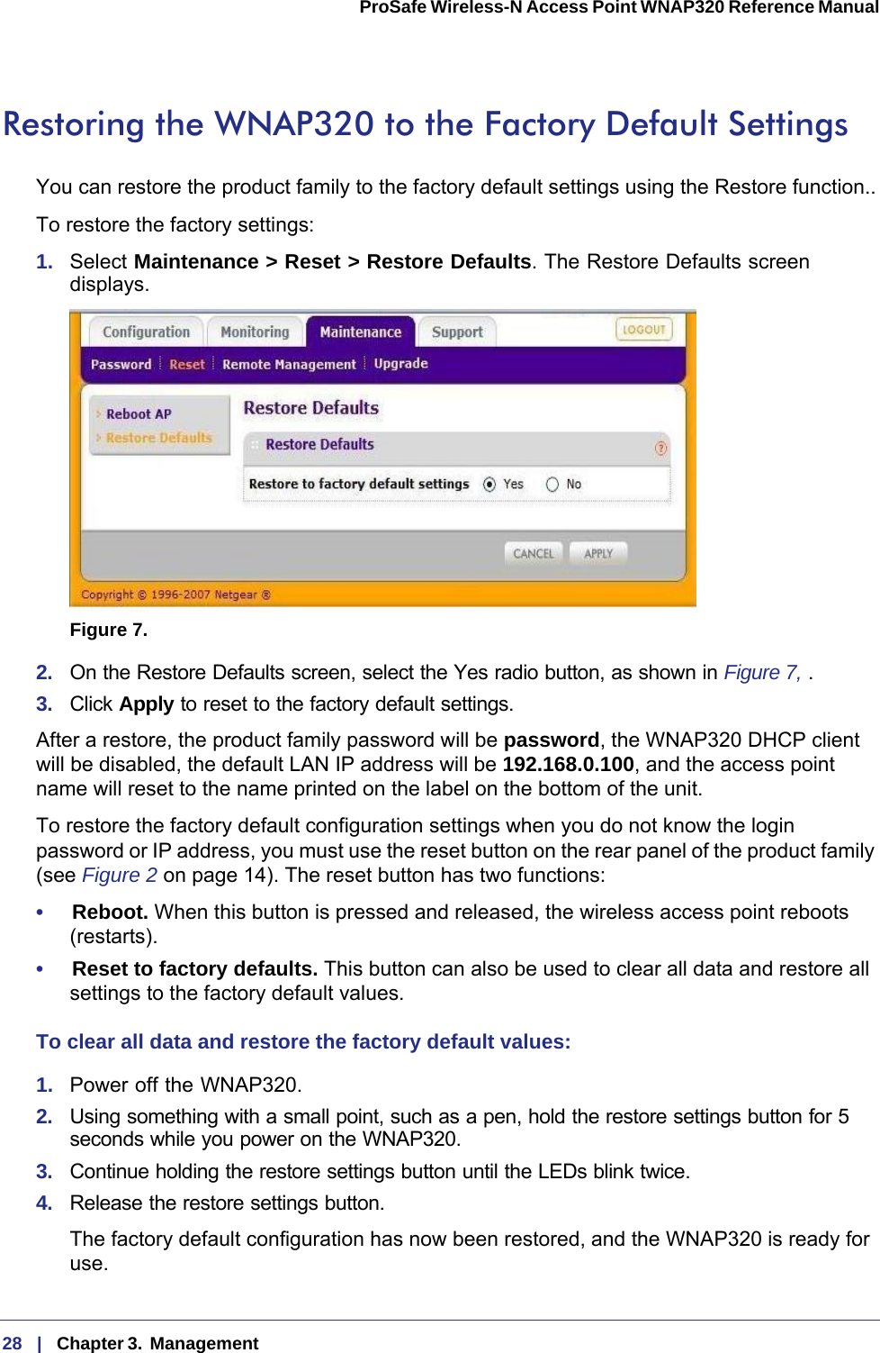

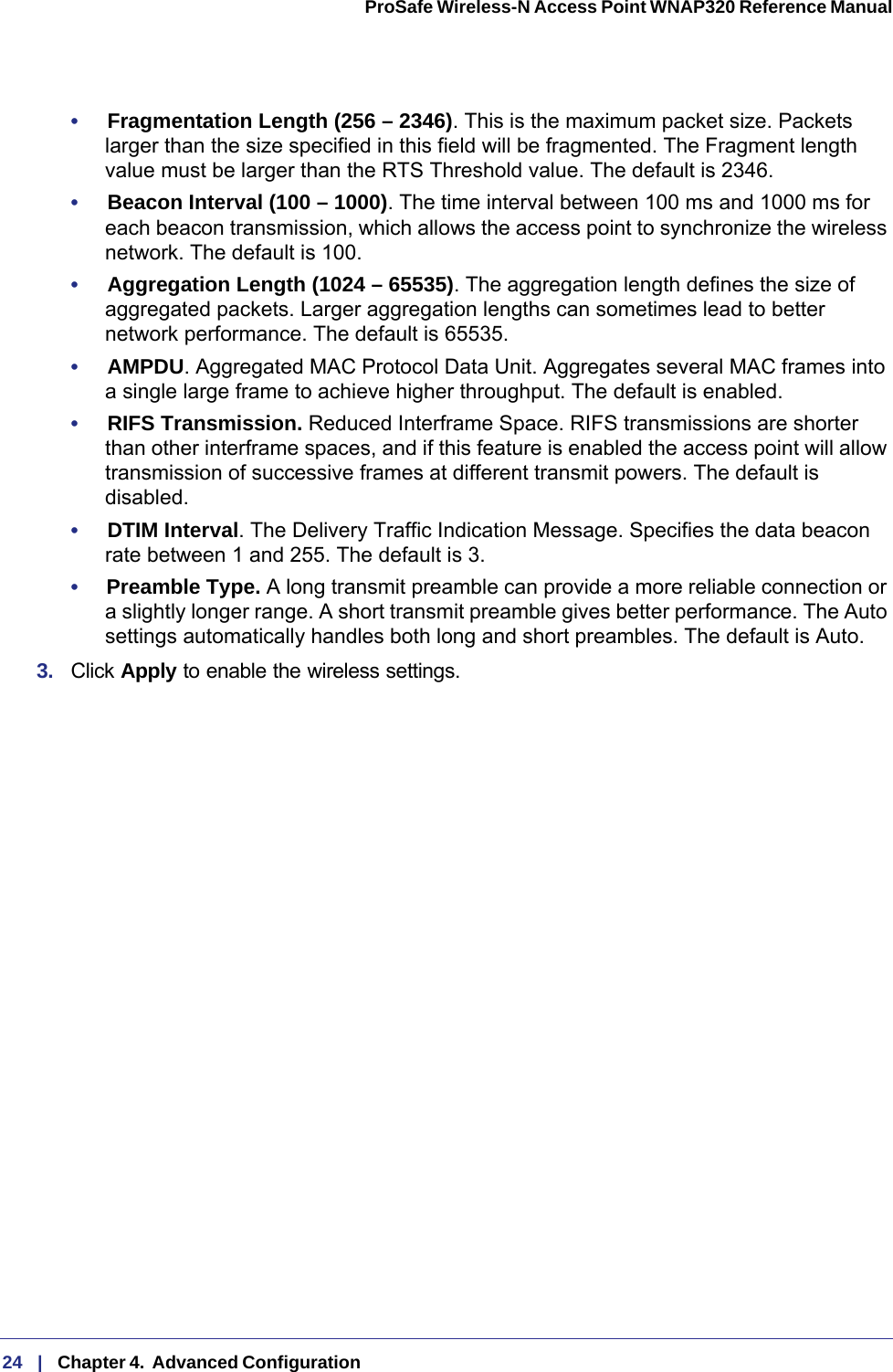
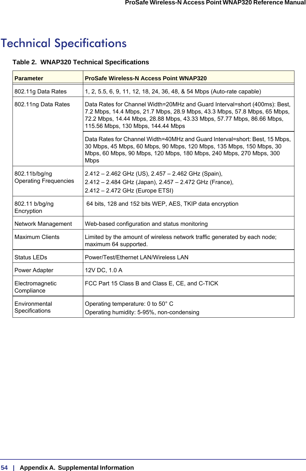
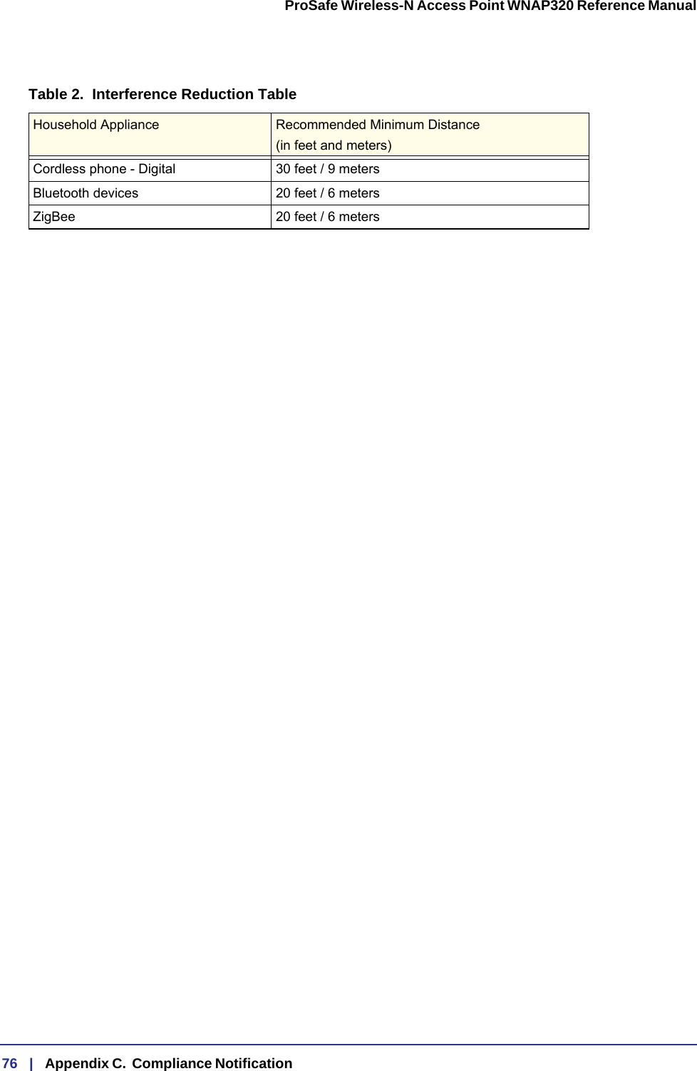
![74 | Appendix C. Compliance Notification ProSafe Wireless-N Access Point WNAP320 Reference Manual • In Italy, the end-user should apply for a license at the national spectrum authorities in order to obtain authorization to use the device for setting up outdoor radio links and/or for supplying public access to telecommunications and/or network services.• This device may not be used for setting up outdoor radio links in France, and in some areas the RF output power may be limited to 10 mW EIRP in the frequency range of 2454 – 2483.5 MHz. For detailed information contact the national spectrum authority in France. For complete DoC, visit the NETGEAR EU Declarations of Conformity website at:: http://kb.netgear.com/app/answers/detail/a_id/11621/Table 1. EDOC in Languages of the European CommunityLanguage StatementCesky [Czech] NETGEAR Inc. tímto prohlašuje, že tento Radiolan je ve shode se základními požadavky a dalšími príslušnými ustanoveními smernice 1999/5/ES.Dansk [Danish] Undertegnede NETGEAR Inc. erklærer herved, at følgende udstyr Radiolan overholder de væsentlige krav og øvrige relevante krav i direktiv 1999/5/EF.Deutsch [German] Hiermit erklärt NETGEAR Inc., dass sich das Gerät Radiolan in Übereinstimmung mit den grundlegenden Anforderungen und den übrigen einschlägigen Bestimmungen der Richtlinie 1999/5/EG befindet.Eesti [Estonian] Käesolevaga kinnitab NETGEAR Inc. seadme Radiolan vastavust direktiivi 1999/5/EÜ põhinõuetele ja nimetatud direktiivist tulenevatele teistele asjakohastele sätetele.English Hereby, NETGEAR Inc., declares that this Radiolan is in compliance with the essential requirements and other relevant provisions of Directive 1999/5/EC.Español [Spanish] Por medio de la presente NETGEAR Inc. declara que el Radiolan cumple con los requisitos esenciales y cualesquiera otras disposiciones aplicables o exigibles de la Directiva 1999/5/CE.Ελληνική [Greek] ΜΕ ΤΗΝ ΠΑΡΟΥΣΑ NETGEAR Inc. ΔΗΛΩΝΕΙ ΟΤΙ Radiolan ΣΥΜΜΟΡΦΩΝΕΤΑΙ ΠΡΟΣ ΤΙΣ ΟΥΣΙΩΔΕΙΣ ΑΠΑΙΤΗΣΕΙΣ ΚΑΙ ΤΙΣ ΛΟΙΠΕΣ ΣΧΕΤΙΚΕΣ ΔΙΑΤΑΞΕΙΣ ΤΗΣ ΟΔΗΓΙΑΣ 1999/5/ΕΚ.Français [French] Par la présente NETGEAR Inc. déclare que l'appareil Radiolan est conforme aux exigences essentielles et aux autres dispositions pertinentes de la directive 1999/5/CE.Italiano [Italian] Con la presente NETGEAR Inc. dichiara che questo Radiolan è conforme ai requisiti essenziali ed alle altre disposizioni pertinenti stabilite dalla direttiva 1999/5/CE.Latviski [Latvian] Ar šo NETGEAR Inc. deklarē, ka Radiolan atbilst Direktīvas 1999/5/EK būtiskajām prasībām un citiem ar to saistītajiem noteikumiem.Lietuvių [Lithuanian] Šiuo NETGEAR Inc. deklaruoja, kad šis Radiolan atitinka esminius reikalavimus ir kitas 1999/5/EB Direktyvos nuostatas.](https://usermanual.wiki/Netgear-orporated/10300138/User-Guide-1363735-Page-91.png)
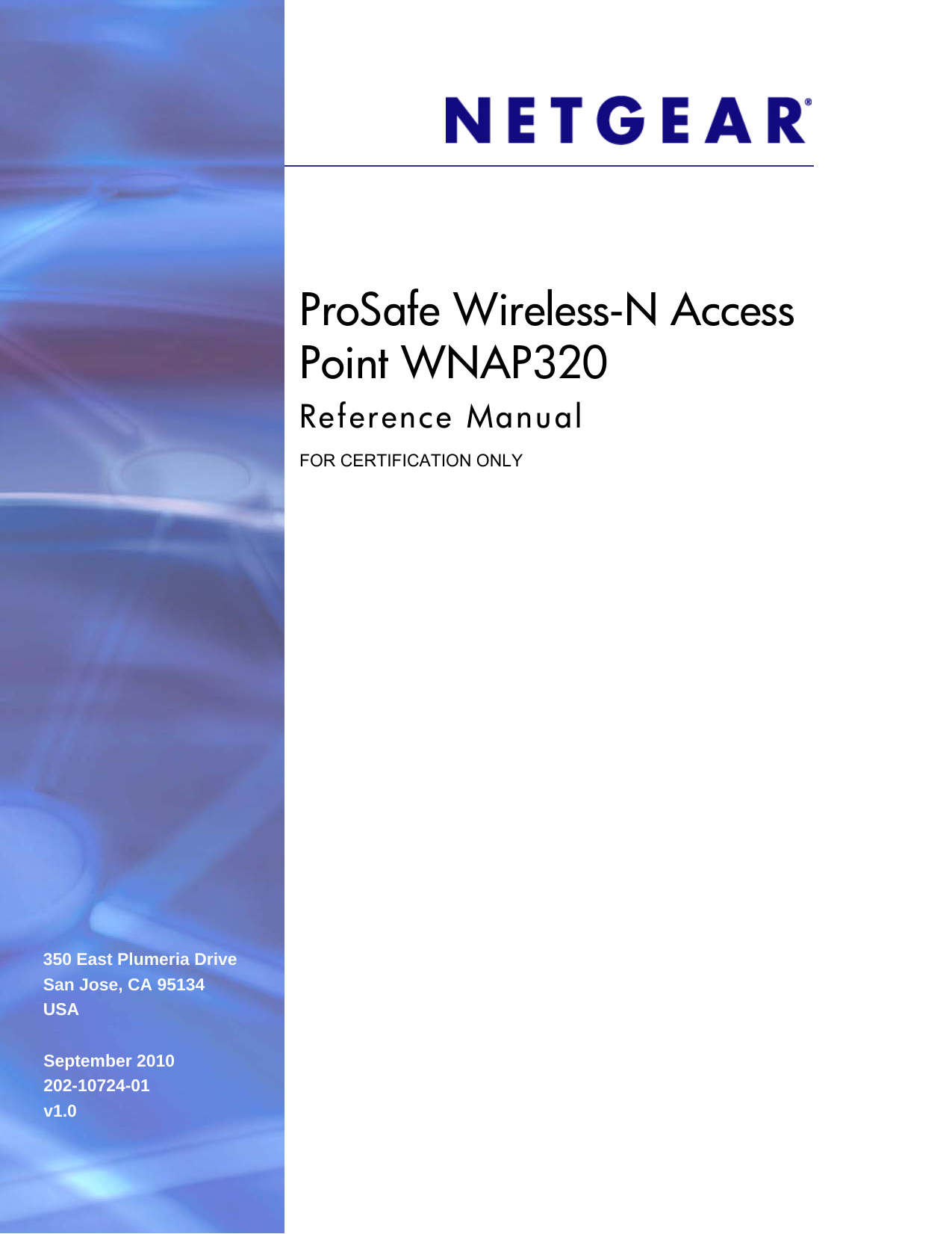
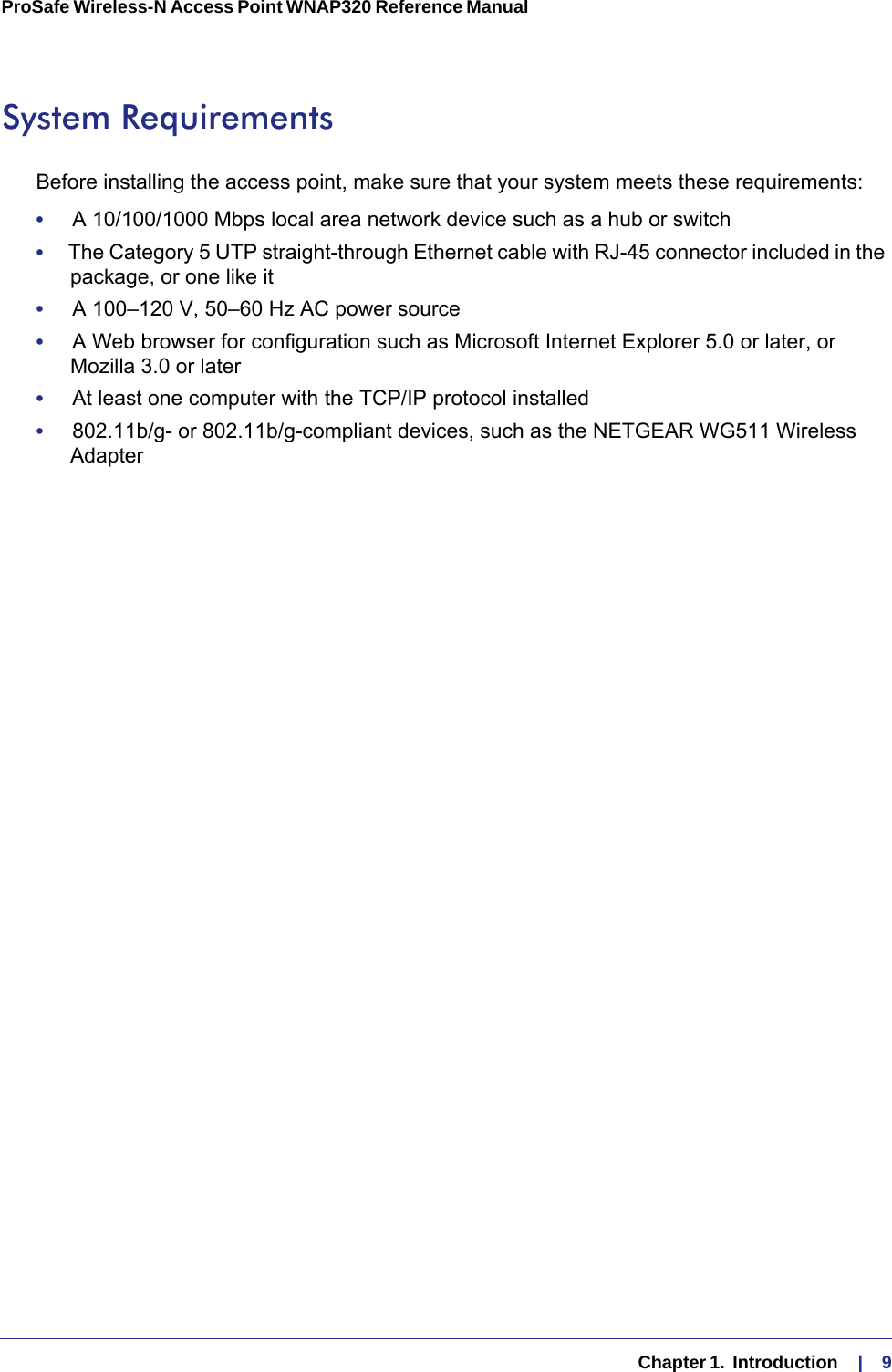
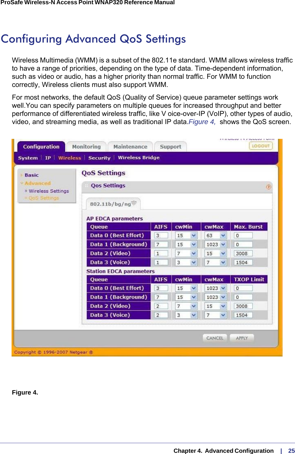
![Appendix C. Compliance Notification | 75ProSafe Wireless-N Access Point WNAP320 Reference Manual Interference Reduction TableThe table below shows the Recommended Minimum Distance between NETGEAR equipment and household appliances to reduce interference (in feet and meters).Nederlands [Dutch] Hierbij verklaart NETGEAR Inc. dat het toestel Radiolan in overeenstemming is met de essentiële eisen en de andere relevante bepalingen van richtlijn 1999/5/EG.Malti [Maltese] Hawnhekk, NETGEAR Inc., jiddikjara li dan Radiolan jikkonforma mal-htigijiet essenzjali u ma provvedimenti ohrajn relevanti li hemm fid-Dirrettiva 1999/5/EC.Magyar [Hungarian Alulírott, NETGEAR Inc. nyilatkozom, hogy a Radiolan megfelel a vonatkozó alapvetõ követelményeknek és az 1999/5/EC irányelv egyéb elõírásainak.Polski [Polish] Niniejszym NETGEAR Inc. oświadcza, że Radiolan jest zgodny z zasadniczymi wymogami oraz pozostałymi stosownymi postanowieniami Dyrektywy 1999/5/EC.Português [Portuguese] NETGEAR Inc. declara que este Radiolan está conforme com os requisitos essenciais e outras disposições da Directiva 1999/5/CE.Slovensko [Slovenian] NETGEAR Inc. izjavlja, da je ta Radiolan v skladu z bistvenimi zahtevami in ostalimi relevantnimi določili direktive 1999/5/ES.Slovensky [Slovak] NETGEAR Inc. týmto vyhlasuje, že Radiolan spĺňa základné požiadavky a všetky príslušné ustanovenia Smernice 1999/5/ES.Suomi [Finnish] NETGEAR Inc. vakuuttaa täten että Radiolan tyyppinen laite on direktiivin 1999/5/EY oleellisten vaatimusten ja sitä koskevien direktiivin muiden ehtojen mukainen.Svenska [Swedish] Härmed intygar NETGEAR Inc. att denna Radiolan står I överensstämmelse med de väsentliga egenskapskrav och övriga relevanta bestämmelser som framgår av direktiv 1999/5/EG.Íslenska [Icelandic] Hér með lýsir NETGEAR Inc. yfir því að Radiolan er í samræmi við grunnkröfur og aðrar kröfur, sem gerðar eru í tilskipun 1999/5/EC.Norsk [Norwegian] NETGEAR Inc. erklærer herved at utstyret Radiolan er i samsvar med de grunnleggende krav og øvrige relevante krav i direktiv 1999/5/EF.Table 2. Interference Reduction TableHousehold Appliance Recommended Minimum Distance(in feet and meters) Microwave ovens 30 feet / 9 metersBaby Monitor - Analog 20 feet / 6 metersBaby Monitor - Digital 40 feet / 12 metersCordless phone - Analog 20 feet / 6 metersTable 1. EDOC in Languages of the European CommunityLanguage Statement](https://usermanual.wiki/Netgear-orporated/10300138/User-Guide-1363735-Page-92.png)