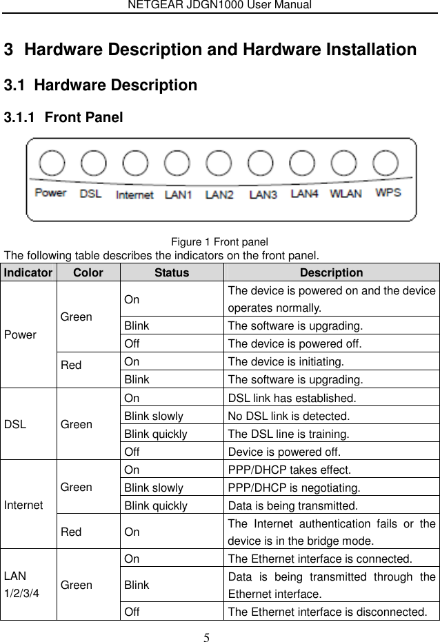
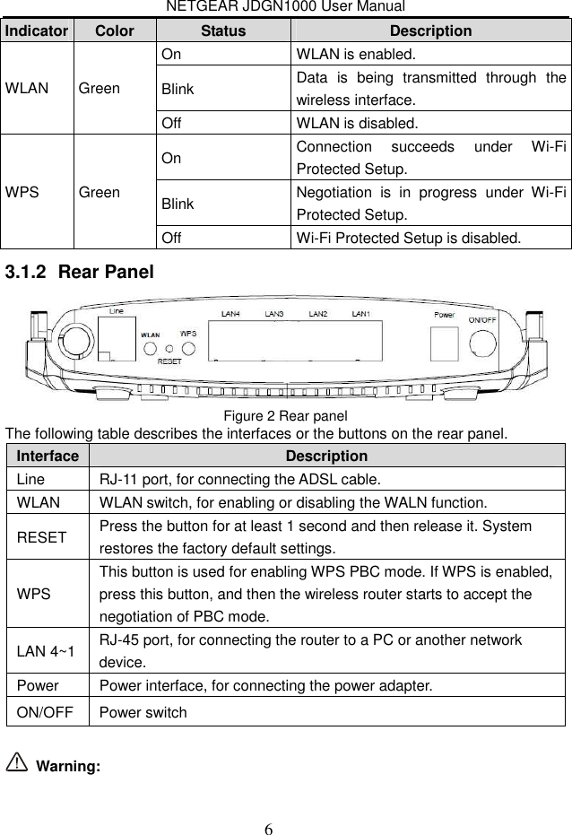
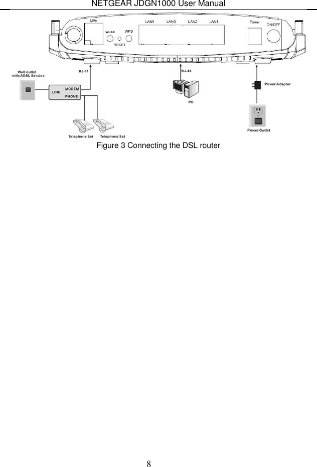
Netgear orporated 11100156 Wireless ADSL2+ Modem Router User Manual NETGEAR JDGN1000
Netgear Incorporated Wireless ADSL2+ Modem Router NETGEAR JDGN1000
UserManual.wiki
>
Netgear orporated
>
11100156 User Manual
>
User Manual 1
Contents
1.
User Manual 1
2.
User Manual 2
User Manual 1
Navigation menu
Upload a User Manual
Namespaces
Wiki Guide
HTML
PDF
Info
Views
User Manual
Discussion / Help
Navigation
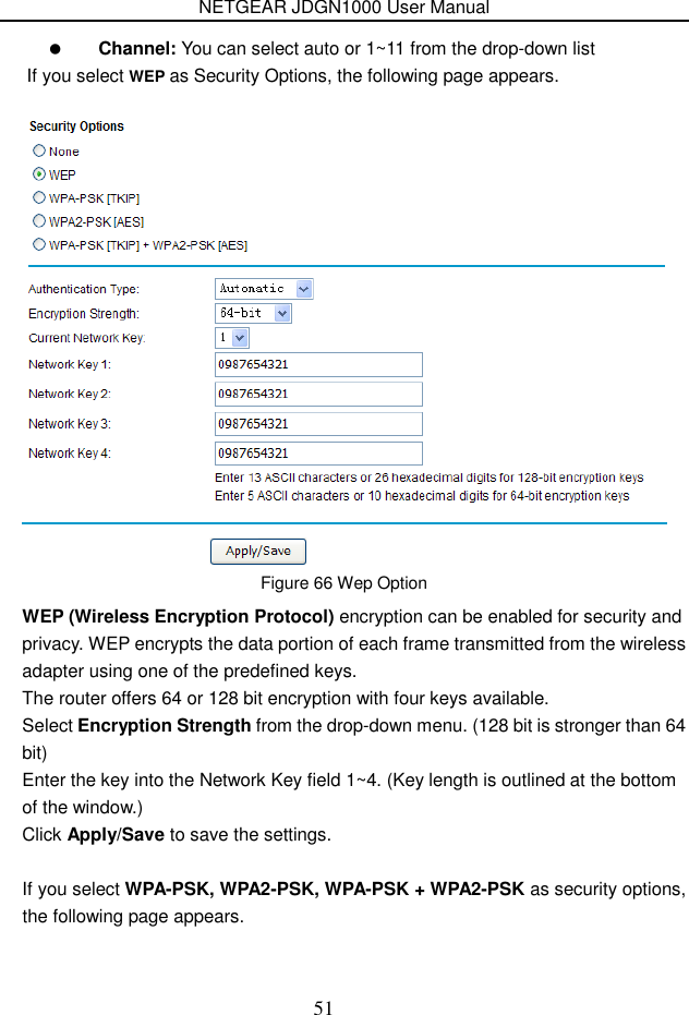
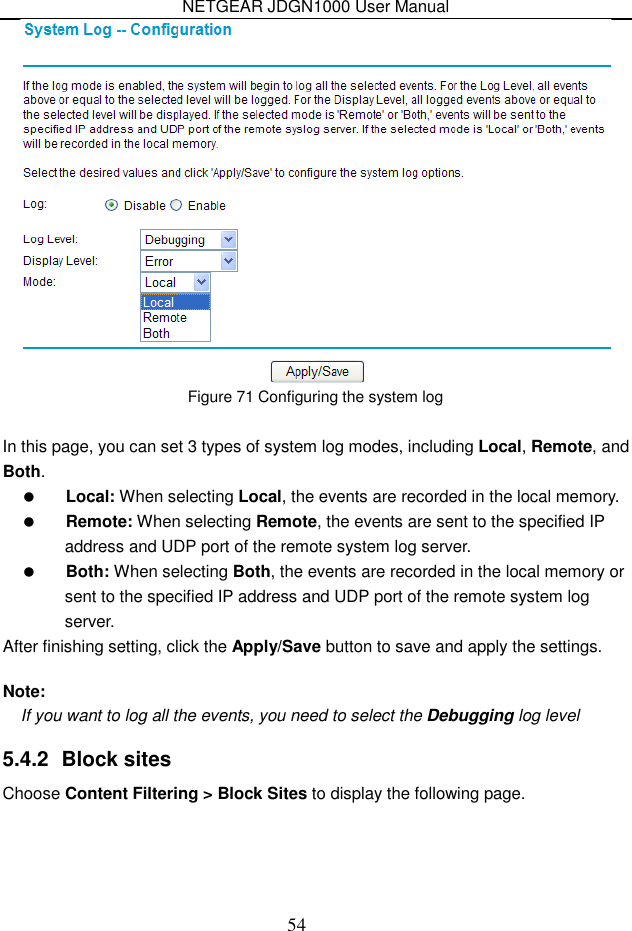
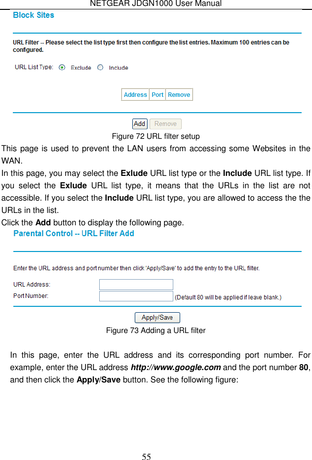
![NETGEAR JDGN1000 User Manual 52 Figure 67 WPA-PSK Option WPA-PSK [TKIP] - Wi-Fi Protected Access with Pre-Shared Key, use WPA-PSK standard encryption with TKIP encryption type WPA2-PSK [AES] - Wi-Fi Protected Access version 2 with Pre-Shared Key, use WPA2-PSK standard encryption with the AES encryption type WPA-PSK [TKIP] + WPA2-PSK [AES] - Allow clients using either WPA-PSK [TKIP] or WPA2-PSK [AES. Enter a word or group of printable characters in the Passphrase box. The Passphrase must be 8 to 63 characters or 64 hex digits in length. 5.4 Content Filtering Choose Content Filtering and the submenus of Content Filtering are shown as below: Figure 68 Submenus of content filtering 5.4.1 Logs Choose Content Filtering > Log to display the following page.](https://usermanual.wiki/Netgear-orporated/11100156.User-Manual-1/User-Guide-1461996-Page-55.png)
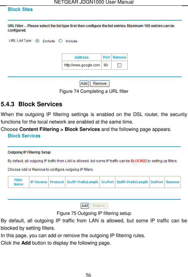
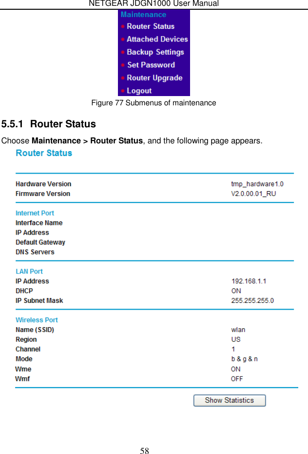
![NETGEAR JDGN1000 User Manual 57 Figure 76 Adding an IP outgoing filtering rule In this page, you can create a filter rule to identify the outgoing IP traffic by specifying a new filter name and at least one condition. Filter Name: Set the filter name. IP Version: Select the proper IP version in the drop-down list. Protocol: Select a protocol that needs to be filtered. Source IP address [/prefix length]: Set the range of local IP address. Source Port (port or port: port): Set the local port. Destination IP address [/prefix length]: Set the range of IP address of the exterior network. Destination Port (port or port: port): Set the port of the exterior network. After finishing setting, click Apply/Save to save and activate the filtering rule. 5.5 Maintenance Choose Maintenance and the submenus of Maintenance are shown as below:](https://usermanual.wiki/Netgear-orporated/11100156.User-Manual-1/User-Guide-1461996-Page-60.png)