Netgear orporated 12200196 N300 Wireless Router with External Antennas User Manual
Netgear Incorporated N300 Wireless Router with External Antennas
User Manual

350 East Plumeria Drive
San Jose, CA 95134
USA
May 2012
202-11058-01
v1.0
N300 Wireless Router with
External Antennas
WNR1500
User Manual
2 |
NETGEAR N300 Wireless Router with External Antennas WNR1500 User Manual

| 3
NETGEAR N300 Wireless Router with External Antennas WNR1500 User Manual
© 2012 NETGEAR, Inc. All rights reserved
No part of this publication may be reproduced, transmitted, transcribed, stored in a retrieval system, or translated
into any language in any form or by any means without the written permission of NETGEAR, Inc.
Technical Support
Thank you for choosing NETGEAR. To register your product, get the latest product updates, get support online, or
for more information about the topics covered in this manual, visit the Support website at
http://support.netgear.com.
Phone (US & Canada only): 1-888-NETGEAR
Phone (Other Countries): Check the list of phone numbers at
http://support.netgear.com/app/answers/detail/a_id/984
Trademarks
NETGEAR, the NETGEAR logo, and Connect with Innovation are trademarks and/or registered trademarks of
NETGEAR, Inc. and/or its subsidiaries in the United States and/or other countries. Information is subject to
change without notice. Other brand and product names are trademarks or registered trademarks of their
respective holders. © 2012 NETGEAR, Inc.
All rights reserved.
Statement of Conditions
To improve internal design, operational function, and/or reliability, NETGEAR reserves the right to make changes
to the products described in this document without notice. NETGEAR does not assume any liability that may
occur due to the use, or application of, the product(s) or circuit layout(s) described herein.

Contents | 3
Contents
Chapter 1 Hardware Setup
Unpack Your Router. . . . . . . . . . . . . . . . . . . . . . . . . . . . . . . . . . . . . . . . . . .7
Hardware Features. . . . . . . . . . . . . . . . . . . . . . . . . . . . . . . . . . . . . . . . . . . .7
Label. . . . . . . . . . . . . . . . . . . . . . . . . . . . . . . . . . . . . . . . . . . . . . . . . . . . .7
Back Panel . . . . . . . . . . . . . . . . . . . . . . . . . . . . . . . . . . . . . . . . . . . . . . . .9
Position Your Router . . . . . . . . . . . . . . . . . . . . . . . . . . . . . . . . . . . . . . . . .10
Cable Your Router . . . . . . . . . . . . . . . . . . . . . . . . . . . . . . . . . . . . . . . . . . .11
Verify the Cabling . . . . . . . . . . . . . . . . . . . . . . . . . . . . . . . . . . . . . . . . . . . .14
Chapter 2 Router Internet Setup
Router Setup Preparation. . . . . . . . . . . . . . . . . . . . . . . . . . . . . . . . . . . . . .16
Use Standard TCP/IP Properties for DHCP . . . . . . . . . . . . . . . . . . . . . .16
Replace an Existing Router . . . . . . . . . . . . . . . . . . . . . . . . . . . . . . . . . .16
Gather ISP Information. . . . . . . . . . . . . . . . . . . . . . . . . . . . . . . . . . . . . .16
Log In to the Router . . . . . . . . . . . . . . . . . . . . . . . . . . . . . . . . . . . . . . . . . .17
Upgrade Router Firmware . . . . . . . . . . . . . . . . . . . . . . . . . . . . . . . . . . .18
Router Interface . . . . . . . . . . . . . . . . . . . . . . . . . . . . . . . . . . . . . . . . . . . . .19
Select a Language for Your Screen Display. . . . . . . . . . . . . . . . . . . . . . . .20
Setup Wizard . . . . . . . . . . . . . . . . . . . . . . . . . . . . . . . . . . . . . . . . . . . . . . .21
Manual Setup (Basic Settings) . . . . . . . . . . . . . . . . . . . . . . . . . . . . . . . . . .21
Basic Settings Screen . . . . . . . . . . . . . . . . . . . . . . . . . . . . . . . . . . . . . .22
Unsuccessful Internet Connection . . . . . . . . . . . . . . . . . . . . . . . . . . . . . . .24
Change Password . . . . . . . . . . . . . . . . . . . . . . . . . . . . . . . . . . . . . . . . . . .25
Log Out Manually . . . . . . . . . . . . . . . . . . . . . . . . . . . . . . . . . . . . . . . . . . . .26
Types of Logins . . . . . . . . . . . . . . . . . . . . . . . . . . . . . . . . . . . . . . . . . . . . .26
Chapter 3 Wireless Settings
Security Basics. . . . . . . . . . . . . . . . . . . . . . . . . . . . . . . . . . . . . . . . . . . . . .28
Turn Off Wireless Connectivity . . . . . . . . . . . . . . . . . . . . . . . . . . . . . . . .28
Disable SSID Broadcast . . . . . . . . . . . . . . . . . . . . . . . . . . . . . . . . . . . . .28
Restrict Access by MAC Address. . . . . . . . . . . . . . . . . . . . . . . . . . . . . .28
Wireless Security Options . . . . . . . . . . . . . . . . . . . . . . . . . . . . . . . . . . .29
Add Clients (Computers or Devices) to Your Network . . . . . . . . . . . . . . . .30
Manual Method. . . . . . . . . . . . . . . . . . . . . . . . . . . . . . . . . . . . . . . . . . . .30
Wi-Fi Protected Setup (WPS) Method . . . . . . . . . . . . . . . . . . . . . . . . . .30
Wireless Settings . . . . . . . . . . . . . . . . . . . . . . . . . . . . . . . . . . . . . . . . . . . .31
Consider Every Device on Your Network . . . . . . . . . . . . . . . . . . . . . . . .32
View or Change Wireless Settings . . . . . . . . . . . . . . . . . . . . . . . . . . . . .32

4 | Contents
NETGEAR N300 Wireless Router JWNR2000T User Manual
Wireless Settings Screen Fields. . . . . . . . . . . . . . . . . . . . . . . . . . . . . . . 33
Set Up WPA-PSK and WPA2-PSK Wireless Security . . . . . . . . . . . . . . 34
Set Up WEP Wireless Security. . . . . . . . . . . . . . . . . . . . . . . . . . . . . . . . 35
Add Guest Networks . . . . . . . . . . . . . . . . . . . . . . . . . . . . . . . . . . . . . . . . .36
Chapter 4 Content Filtering
Live Parental Controls . . . . . . . . . . . . . . . . . . . . . . . . . . . . . . . . . . . . . . . . 39
Keyword Blocking of HTTP Traffic . . . . . . . . . . . . . . . . . . . . . . . . . . . . . . .39
Delete a Keyword or Domain . . . . . . . . . . . . . . . . . . . . . . . . . . . . . . . . . 40
Specify a Trusted Computer. . . . . . . . . . . . . . . . . . . . . . . . . . . . . . . . . . 40
Block Outbound Traffic to Internet Services. . . . . . . . . . . . . . . . . . . . . . . . 40
Block Services by IP Address Range. . . . . . . . . . . . . . . . . . . . . . . . . . . 42
Set the Time Zone . . . . . . . . . . . . . . . . . . . . . . . . . . . . . . . . . . . . . . . . . . . 42
Schedule Blocking . . . . . . . . . . . . . . . . . . . . . . . . . . . . . . . . . . . . . . . . . . . 43
Enable Security Event Email Notification . . . . . . . . . . . . . . . . . . . . . . . . . .44
View Logs of Web Access or Attempted Web Access . . . . . . . . . . . . . . . .45
Allow Inbound Connections to Your Network. . . . . . . . . . . . . . . . . . . . . . .46
Port Forwarding to a Local Server . . . . . . . . . . . . . . . . . . . . . . . . . . . . . . .47
Add a Custom Service . . . . . . . . . . . . . . . . . . . . . . . . . . . . . . . . . . . . . . 48
Edit or Delete a Port Forwarding Entry. . . . . . . . . . . . . . . . . . . . . . . . . . 49
Port Triggering . . . . . . . . . . . . . . . . . . . . . . . . . . . . . . . . . . . . . . . . . . . . . . 50
Chapter 5 Network Maintenance
Upgrade the Router Firmware . . . . . . . . . . . . . . . . . . . . . . . . . . . . . . . . . . 54
Turn Off Automatic Firmware Checking . . . . . . . . . . . . . . . . . . . . . . . . . 54
Automatic Firmware Checking On . . . . . . . . . . . . . . . . . . . . . . . . . . . . . 55
Manually Check for Firmware Upgrades . . . . . . . . . . . . . . . . . . . . . . . . 55
Manage the Configuration File . . . . . . . . . . . . . . . . . . . . . . . . . . . . . . . . . .56
Back Up . . . . . . . . . . . . . . . . . . . . . . . . . . . . . . . . . . . . . . . . . . . . . . . . . 56
Restore. . . . . . . . . . . . . . . . . . . . . . . . . . . . . . . . . . . . . . . . . . . . . . . . . . 57
Erase . . . . . . . . . . . . . . . . . . . . . . . . . . . . . . . . . . . . . . . . . . . . . . . . . . . 57
View Router Status. . . . . . . . . . . . . . . . . . . . . . . . . . . . . . . . . . . . . . . . . . . 58
View Attached Devices. . . . . . . . . . . . . . . . . . . . . . . . . . . . . . . . . . . . . . . . 61
Remote Management Access . . . . . . . . . . . . . . . . . . . . . . . . . . . . . . . . . . 61
Chapter 6 Advanced Settings
WAN Setup. . . . . . . . . . . . . . . . . . . . . . . . . . . . . . . . . . . . . . . . . . . . . . . . . 64
Set Up a Default DMZ Server. . . . . . . . . . . . . . . . . . . . . . . . . . . . . . . . . 65
Dynamic DNS. . . . . . . . . . . . . . . . . . . . . . . . . . . . . . . . . . . . . . . . . . . . . . . 65
LAN Setup . . . . . . . . . . . . . . . . . . . . . . . . . . . . . . . . . . . . . . . . . . . . . . . . . 67
LAN Setup Screen Fields . . . . . . . . . . . . . . . . . . . . . . . . . . . . . . . . . . . . 68
Use the Router as a DHCP Server. . . . . . . . . . . . . . . . . . . . . . . . . . . . . 68
Reserved IP Addresses Setup . . . . . . . . . . . . . . . . . . . . . . . . . . . . . . . . 69
Advanced Wireless Settings. . . . . . . . . . . . . . . . . . . . . . . . . . . . . . . . . . . . 70
Restrict Wireless Access by MAC Address . . . . . . . . . . . . . . . . . . . . . . 71
Set Up Static Routes . . . . . . . . . . . . . . . . . . . . . . . . . . . . . . . . . . . . . . . . . 73

Contents | 5
NETGEAR N300 Wireless Router JWNR2000T User Manual
Quality of Service . . . . . . . . . . . . . . . . . . . . . . . . . . . . . . . . . . . . . . . . . . . .74
WMM QoS for Wireless Multimedia Applications . . . . . . . . . . . . . . . . . .75
QoS for Internet Access . . . . . . . . . . . . . . . . . . . . . . . . . . . . . . . . . . . . .75
Traffic Meter . . . . . . . . . . . . . . . . . . . . . . . . . . . . . . . . . . . . . . . . . . . . . . . .79
Universal Plug and Play . . . . . . . . . . . . . . . . . . . . . . . . . . . . . . . . . . . . . . .80
Wireless Repeating (Also Called WDS) . . . . . . . . . . . . . . . . . . . . . . . . . . .81
Wireless Repeating Function . . . . . . . . . . . . . . . . . . . . . . . . . . . . . . . . .82
Set Up the Base Station . . . . . . . . . . . . . . . . . . . . . . . . . . . . . . . . . . . . .82
Set Up a Repeater Unit. . . . . . . . . . . . . . . . . . . . . . . . . . . . . . . . . . . . . .83
Chapter 7 Troubleshooting
Quick Tips. . . . . . . . . . . . . . . . . . . . . . . . . . . . . . . . . . . . . . . . . . . . . . . . . .86
Troubleshooting Basic Functions . . . . . . . . . . . . . . . . . . . . . . . . . . . . . . . .86
Login Problems. . . . . . . . . . . . . . . . . . . . . . . . . . . . . . . . . . . . . . . . . . . . . .88
Check the Internet Service Connection . . . . . . . . . . . . . . . . . . . . . . . . . . .89
Obtaining an Internet IP Address . . . . . . . . . . . . . . . . . . . . . . . . . . . . . .89
Troubleshooting PPPoE . . . . . . . . . . . . . . . . . . . . . . . . . . . . . . . . . . . . .90
Troubleshooting Internet Browsing. . . . . . . . . . . . . . . . . . . . . . . . . . . . .90
Troubleshoot Your Network Using the Ping Utility . . . . . . . . . . . . . . . . . . .91
Test the LAN Path to Your Router . . . . . . . . . . . . . . . . . . . . . . . . . . . . .91
Test the Path from Your Computer to a Remote Device . . . . . . . . . . . .92
Problems with Date and Time . . . . . . . . . . . . . . . . . . . . . . . . . . . . . . . . . .92
Problems with Wireless Adapter Connections . . . . . . . . . . . . . . . . . . . . . .93
Restore the Default Configuration and Password . . . . . . . . . . . . . . . . . . .94
Appendix A Supplemental Information
Factory Default Settings . . . . . . . . . . . . . . . . . . . . . . . . . . . . . . . . . . . . . . .96
Specifications . . . . . . . . . . . . . . . . . . . . . . . . . . . . . . . . . . . . . . . . . . . . . . .97
Appendix B Notification of Compliance
Index

Chapter 1. Hardware Setup | 6
1
1. Hardware Setup
Getting to know your router
The NETGEAR N300 Wireless Router with External Antennas WNR1500 User Manual provides
you with an easy and secure way to set up a wireless home network.
For more information on the topics covered in this manual, visit the Support website at
http://support.netgear.com.
If you have not already set up your new router using the installation guide that comes in the box,
this chapter walks you through the hardware setup. The next chapter explains how to set up your
Internet connection.
This chapter contains the following sections:
• Unpack Your Router
• Hardware Features
• Position Your Router
• Cable Your Router
• Verify the Cabling
Chapter 1. Hardware Setup | 7
NETGEAR N300 Wireless Router with External Antennas WNR1500 User Manual
Unpack Your Router
Your box should contain the following items:
• N300 Wireless Router with External Antennas WNR1500
• AC power adapter (plug varies by region)
• Category 5 (Cat 5) Ethernet cable
• Installation guide with cabling and router setup instructions
If any parts are incorrect, missing, or damaged, contact your NETGEAR dealer. Keep the
carton and original packing materials, in case you need to return the product for repair.
Hardware Features
Before you cable your router, take a moment to become familiar with the label and the front
and back panels. Pay particular attention to the LEDs on the front panel.
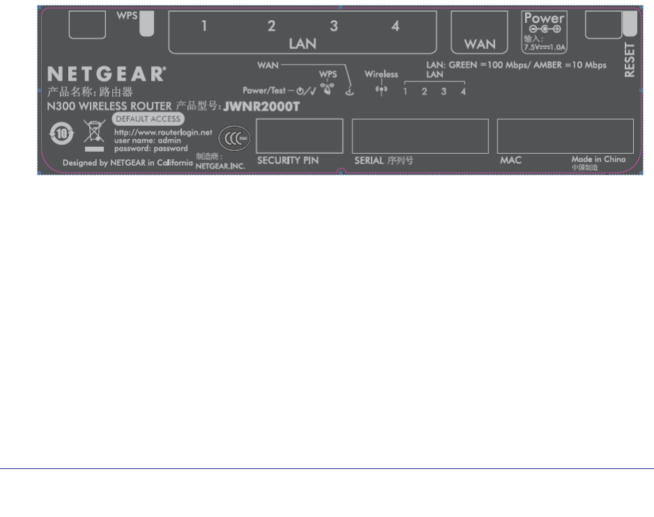
Label
The label on the bottom shows the router’s MAC address, serial number, security PIN, and
login information.
Figure 1. Label on router bottom
8 | Chapter 1. Hardware Setup
NETGEAR N300 Wireless Router with External Antennas WNR1500 User Manual
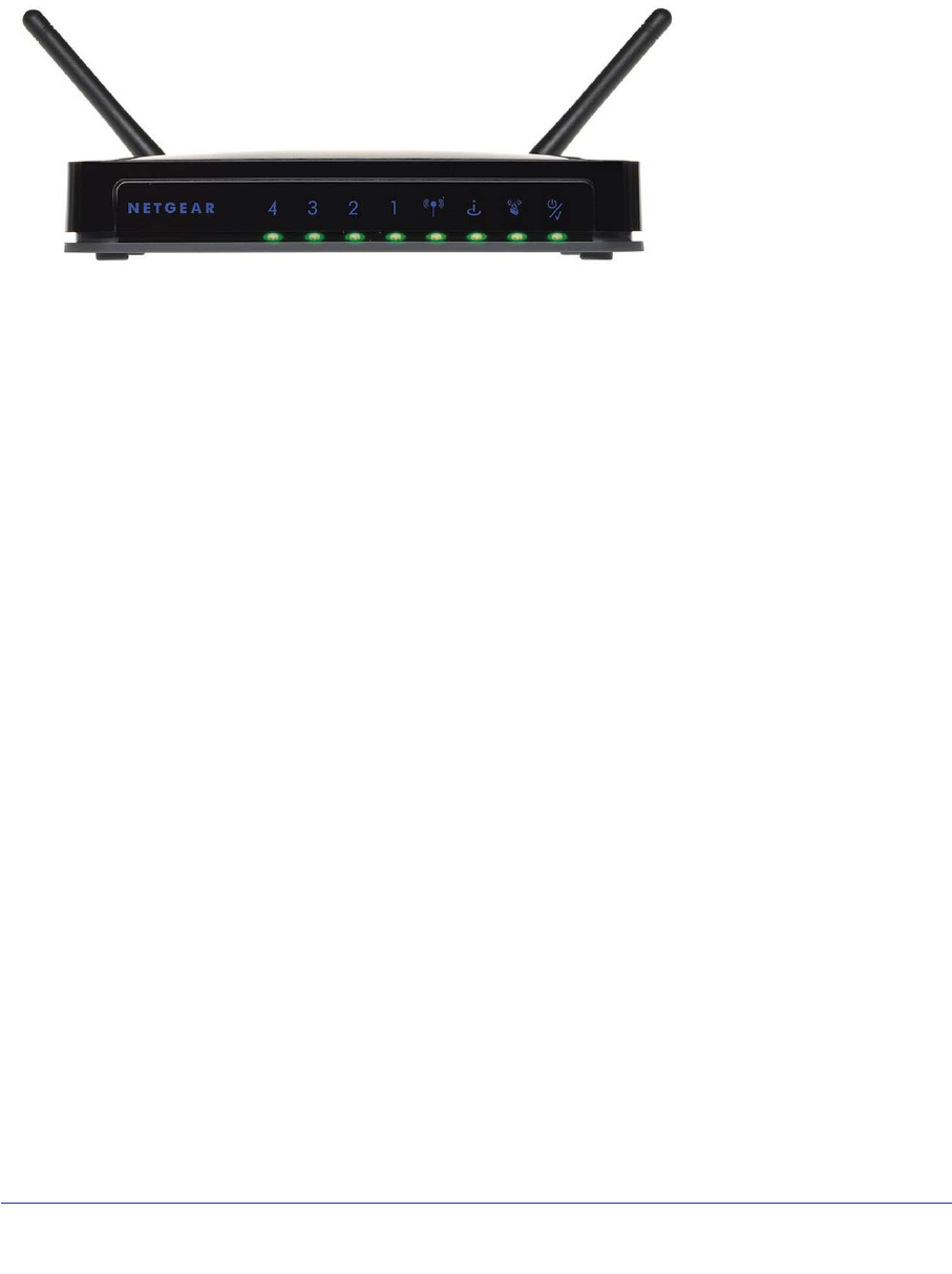
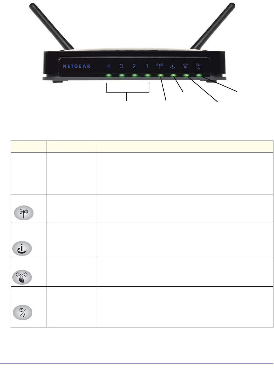
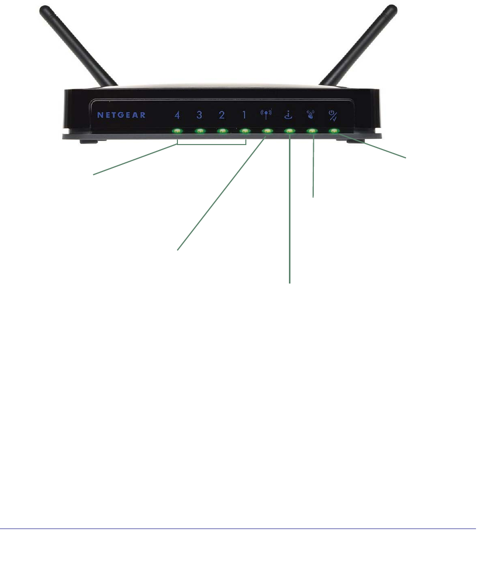
The router front panel has status LEDs and icons shown in the figure.
Internet
WPS
Power/Check
Wireless
LAN ports
Figure 2. Front panel LEDs and icons
Table 1. Front Panel LEDs
Icon LED Activity Description
LAN ports
1–4
Solid green
Blinking green
Solid amber
Blinking amber
Off
The local port is connected to a 100 Mbps device.
Data is being transmitted at 100 Mbps.
The local port is connected to a 10 Mbps device.
Data is being transmitted at 10 Mbps.
No link is detected on this port.
Wireless Solid green
Blinking green
Off
The wireless interface is enabled.
Data is being communicated over the wireless network.
The wireless interface is turned off.
Internet
(WAN)
Solid green
Blinking green
Off
The router has acquired an Internet address.
Data is being communicated with the Internet.
No Ethernet cable is connected to the modem.
WPS Solid green
Blinking green
Off
Indicates a (WPS) connection to a WPS-capable device.
WPS-capable device can associate with the router within 2 minutes.
No WPS connection exists.
Power/
Check
Solid green
Fast blink green
Slow blink green
Off
The power is on and the router is ready.
A software update is in progress.
Performing basic power-on self-test diagnostic, or firmware is corrupted
(see Troubleshooting Basic Functions on page 86).
Power is not being supplied to the router
Chapter 1. Hardware Setup | 9
NETGEAR N300 Wireless Router with External Antennas WNR1500 User Manual
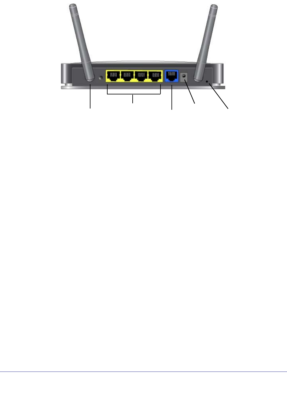
Back Panel
The back panel has the following features:
WPS Ethernet LAN Internet Power Reset
Figure 3. Back panel

10 | Chapter 1. Hardware Setup
NETGEAR N300 Wireless Router with External Antennas WNR1500 User Manual
Position Your Router
The router lets you access your network from virtually anywhere within the operating range of
your wireless network. However, the operating distance or range of your wireless connection
can vary significantly depending on the physical placement of your router. For example, the
thickness and number of walls the wireless signal passes through can limit the range. For
best results, place your router:
• Near the center of the area where your computers and other devices operate, and
preferably within line of sight to your wireless devices.
• So it is accessible to an AC power outlet and near Ethernet cables for wired computers.
• In an elevated location such as a high shelf, keeping the number of walls and ceilings
between the router and your other devices to a minimum.
• Away from electrical devices that are potential sources of interference, such as ceiling
fans, home security systems, microwaves, PCs, or the base of a cordless phone or 2.4
GHz cordless phone.
• Away from any large metal surfaces, such as a solid metal door or aluminum studs. Large
expanses of other materials such as glass, insulated walls, fish tanks, mirrors, brick, and
concrete can also affect your wireless signal.
• With the antennas in a vertical position to provide the best side-to-side coverage or in a
horizontal position to provide the best up-and-down coverage, as applicable.
When you use multiple access points, it is better if adjacent access points use different radio
frequency channels to reduce interference. The recommended channel spacing between
adjacent access points is 5 channels (for example, use Channels 1 and 6, or 6 and 11).
Chapter 1. Hardware Setup | 11
NETGEAR N300 Wireless Router with External Antennas WNR1500 User Manual
Cable Your Router
The installation guide that came in the box has a cabling diagram on the first page. This
section walks you through cabling with detailed illustrations.
To connect the router, the computer, and the modem:
1. Turn off and unplug your broadband modem.
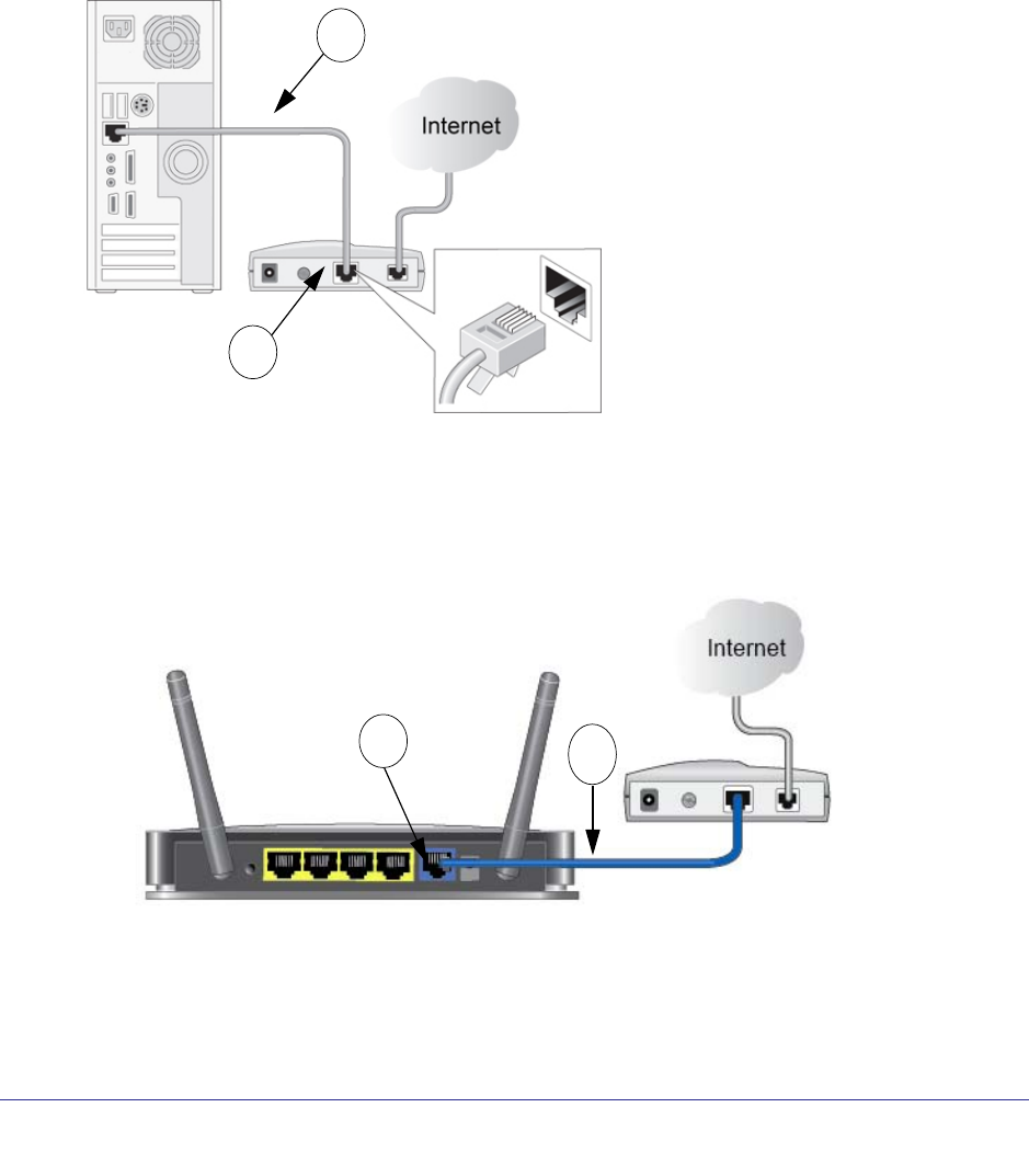
2. Locate the cable (A) that connects your computer to the modem. Disconnect the cable at the
modem end only (B). You will connect it to the router later.
A
B
Figure 4. Disconnect the modem end of the Ethernet cable
3. Connect the blue Ethernet cable (C) that came with the router to the Internet (WAN) port (D)
on the router, and to the Ethernet port on your broadband modem. The cable and the
Internet port label are color coded.
C
D
Figure 5. Use the Ethernet cable to connect the modem to the router
12 | Chapter 1. Hardware Setup
NETGEAR N300 Wireless Router with External Antennas WNR1500 User Manual
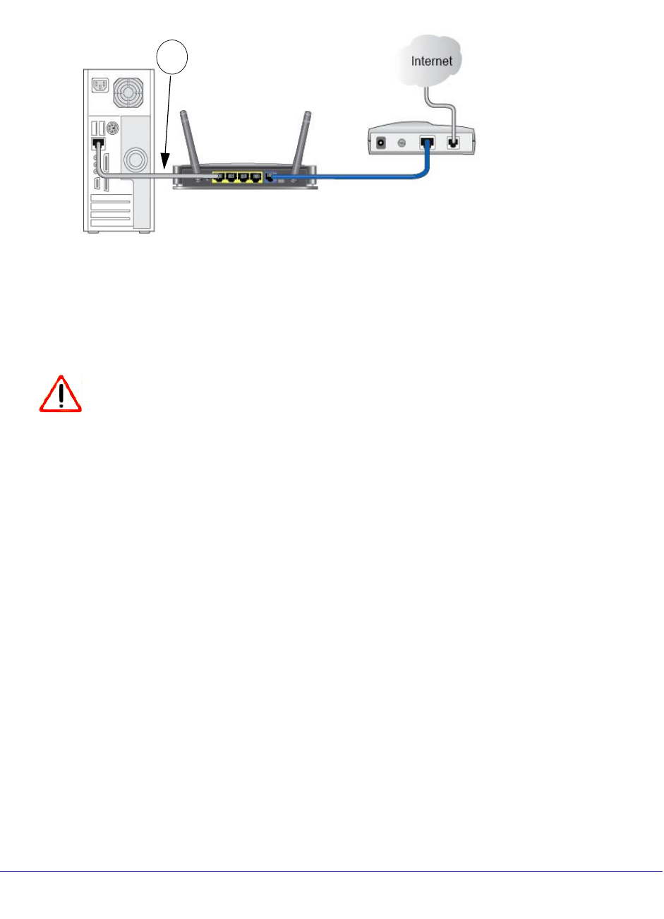
4. Locate the cable (A) that is still attached to your computer. Insert that cable into a yellow
LAN port on the router, as shown in the following figure:
A
Figure 6. Connect the Ethernet cable to a LAN port on the router
5. Connect any additional wired PCs to your router by inserting an Ethernet cable from a PC
into one of the three remaining LAN ports.
6. Start your network in the correct sequence, as described below.
CAUTION:
Failure to start or restart your network in the correct sequence could
prevent you from accessing the Internet.
To start your network:
1. Plug in and turn on the cable or DSL modem. Wait 2 minutes.
Chapter 1. Hardware Setup | 13
NETGEAR N300 Wireless Router with External Antennas WNR1500 User Manual
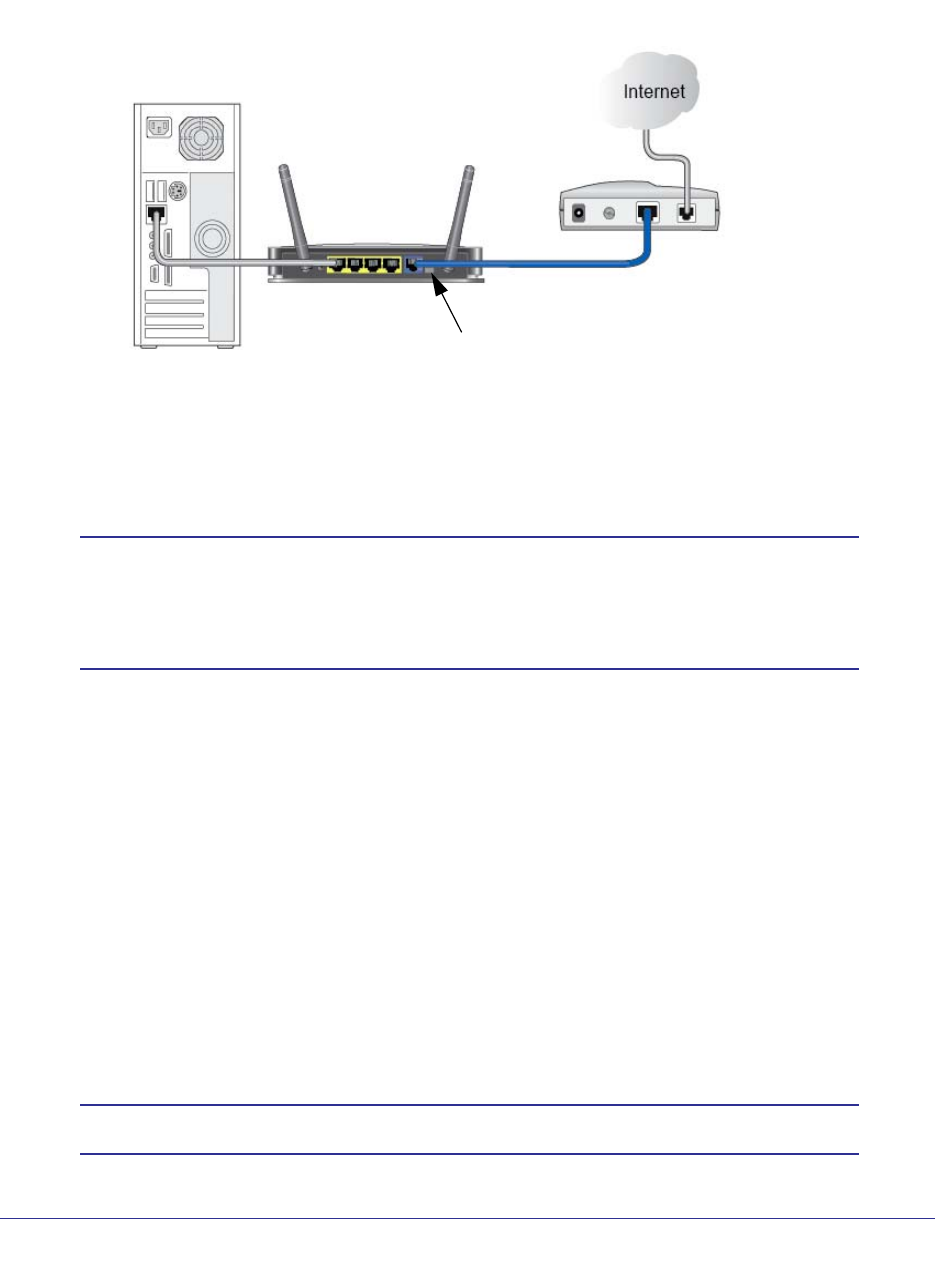
2. Plug the power adapter into the AC power adapter input (labeled Power), and plug the other
end into a power outlet. Press the On/Off button to turn on the router. Wait 2 minutes.
Power adapter
Figure 7. Connect the power adapter cord and turn on the router
It takes several minutes for your router to establish a connection with your computer and
your Internet provider.
Note: For DSL customers, if software logs you in to the Internet, do not run
that software. You might need to go to the Internet Explorer Tools
menu, Internet Options, Connections tab and select “Never dial a
connection.”
3. To set up your Internet connection:
a. In your browser address field, type http://www.routerlogin.net and click Enter.
b. When the Welcome screen opens, click Next. It will detect your type of Internet
connection. Follow the prompts to complete your router Internet connection.
4. To set up wireless security:
a. First, assign a name to your wireless network. Choose a name (SSID) that is easy to
remember. You might want to write it down in the area provided on the middle panel.
(The default name is NETGEAR.) Click Next.
b. Select the Yes option to add security, then select your security method. NETGEAR
recommends WPA-PSK [TKIP] + WPA2-PSK [AES].
c. Choose a Passphrase (for example, HomeNetwork). You might want to write it down
in the area provided on the middle panel. Click Next.
Note: Both your network name (SSID and passphrase are case sensitive.
14 | Chapter 1. Hardware Setup
NETGEAR N300 Wireless Router with External Antennas WNR1500 User Manual
d. Review your network settings on the Success page. You may want to print this for
your records.
e. Click Next to apply all settings.
Verify the Cabling
Verify that your router is cabled correctly, is turned on, and is receiving power by checking the
router LEDs. The following figure shows the LEDs.
Power/Check.
The
Power/Check
LED should
turn solid
green.
Wireless. The wireless
LED should be lit.
Internet (WAN). The
Internet port LED should
be lit. If it is not, make sure
the Ethernet cable is
securely attached to the
router Internet port and the
modem, and that the
modem is powered on.
LAN. A LAN LED (1-4)
should be lit for each port
that has a computer cabled
to it (a wired connection). WPS. The WPS LED
is not lit unless you
pressed the WPS
button on the rear
panel.
Figure 8. Check the LEDs

Chapter 2. Router Internet Setup | 15
2
2. Router Internet Setup
Connecting to the Internet
This chapter explains how to set up your Internet connection using one of three methods:
NETGEAR Genie (recommended), Setup Wizard, or manual setup. If you have already set up
your router using one of these methods, the initial router setup is complete. Refer to this chapter
if you want to become familiar with the router menus, view or adjust the initial settings, or change
the router password and login time-out.
This chapter contains the following sections:
• Router Setup Preparation
• Log In to the Router
• Select a Language for Your Screen Display
• Router Interface
• Setup Wizard
• Manual Setup (Basic Settings)
• Unsuccessful Internet Connection
• Change Password
• Log Out Manually
• Types of Logins

16 | Chapter 2. Router Internet Setup
NETGEAR N300 Wireless Router with External Antennas WNR1500 User Manual
Router Setup Preparation
You can set up your router with the Smart Wizard on the Resource CD as described in the
installation guide with the Setup Wizard (see Setup Wizard on page 21), or manually (see
Manual Setup (Basic Settings) on page 21). Before you start the setup process, you need to
have your ISP information on hand and make sure the laptops, PCs, and other devices in the
network have the settings described here.
Use Standard TCP/IP Properties for DHCP
If you configured your computer to use a static IP address, you need to change the settings
back so that it uses Dynamic Host Configuration Protocol (DHCP). See Appendix A,
Supplemental Information for more information.
Replace an Existing Router
To replace an existing router, disconnect it completely from your network and set it aside
before starting the router setup.
Gather ISP Information
You need the following information to set up your router and to check that your Internet
configuration is correct. Your Internet Service Provider (ISP) should have provided you with
all of the information needed to connect to the Internet. If you cannot locate this information,
ask your ISP to provide it. When your Internet connection is working, you no longer need to
launch the ISP’s login program on your computer to access the Internet. When you start an
Internet application, your router automatically logs you in.
• Active Internet service provided by a DSL account
• The ISP configuration information for your DSL account
-ISP login name and password
-ISP Domain Name Server (DNS) addresses
-Fixed or static IP address
-Host and domain names
-Depending on how your ISP set up your Internet account, you could need to know
one or more of these settings for a manual setup:
- Virtual path identifier (VPI) and virtual channel identifier (VCI) parameters
- Multiplexing method
- Host and domain names
Chapter 2. Router Internet Setup | 17
NETGEAR N300 Wireless Router with External Antennas WNR1500 User Manual
Log In to the Router
Log in to the router to view or change settings or to set up the router.
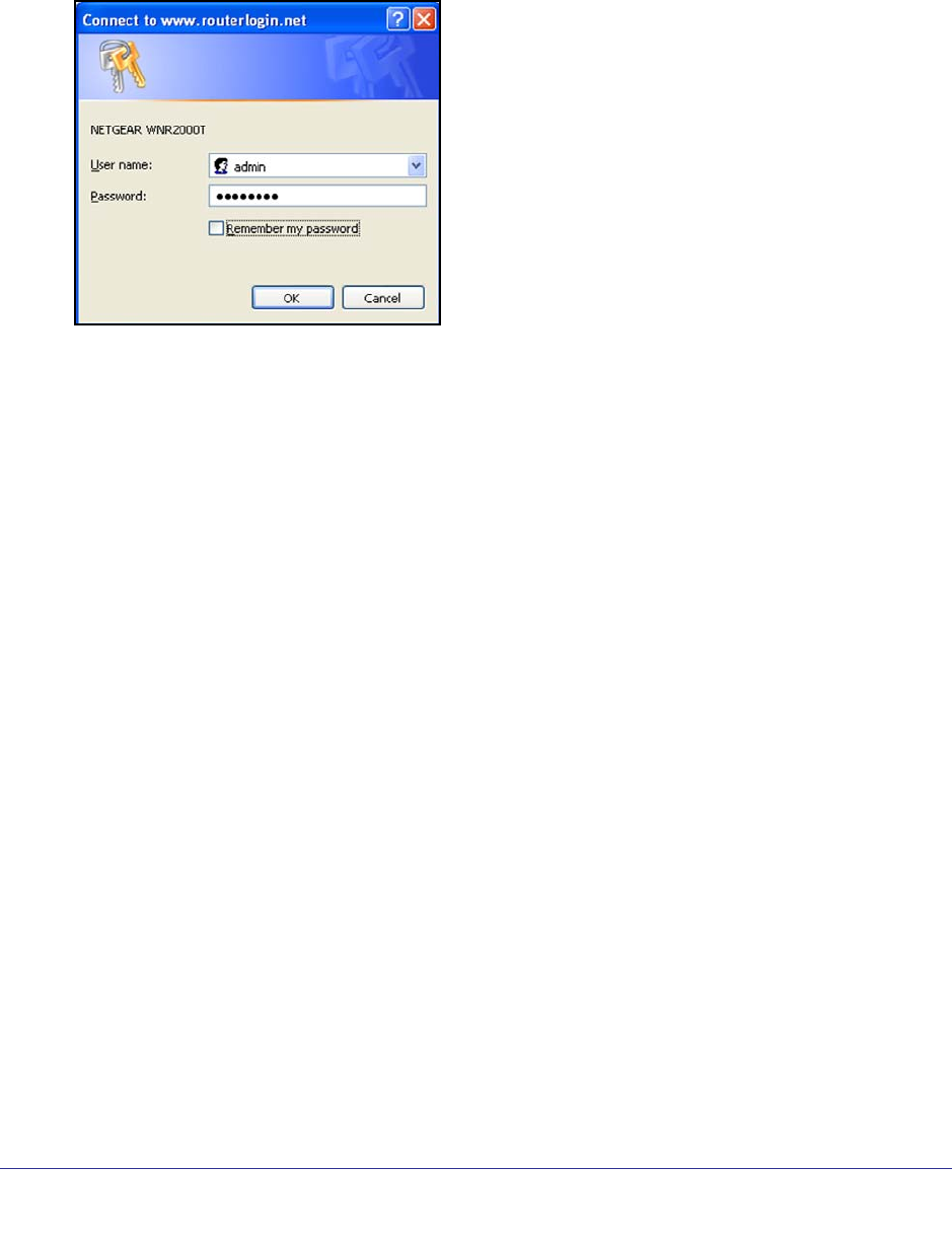
1. In your browser address field, type http://www.routerlogin.net and click Enter.
2. When prompted, enter admin for the router user name and password for the router
password, both in lowercase letters.
Note: The router user name and password are probably different from the user
name and password for logging in to your Internet connection. See Types of
Logins on page 26 for more information.
The router menus display where you can do things like change settings or add other
devices to your network. See Router Interface on page 19 for a brief description of the
available functionality, and Wi-Fi Protected Setup (WPS) Method on page 30 or
information about adding devices to your network.
If you do not see the login prompt:
• Check the LEDs on the router front panel to make sure that the modem router is
plugged into an electrical outlet, its power is on, and the Ethernet cable between your
computer and the router is connected to a LAN port.
• If you connected the Ethernet cable and quickly launched your browser and typed in
the router URL, your computer might need a minute or two to recognize the LAN
connection. Relaunch your browser and try again.
• If you are having trouble accessing the router wirelessly, NETGEAR recommends that
during setup you use an Ethernet cable to connect your computer so that you can log
in to the router.

18 | Chapter 2. Router Internet Setup
NETGEAR N300 Wireless Router with External Antennas WNR1500 User Manual
If you cannot connect to the wireless router, check the Internet Protocol (TCP/IP)
properties in the Network Connections section of your PC Control Panel. They should be
set to obtain both IP and DNS server addresses automatically.
3. When the Welcome screen opens, click Next. It will detect your type of Internet connection.
Follow the prompts to complete your Internet connection.
Upgrade Router Firmware
When you log in and if you are connected to the Internet, the Firmware Upgrade Assistant
screen displays so you can upgrade to the latest available firmware. See Chapter 5, Network
Maintenance for more information about upgrading firmware.
1. Click Yes to check for new firmware (recommended). The modem router checks the
NETGEAR database for new firmware.
2. If no new firmware is available, click No to exit. You can check for new firmware later.
3. If new firmware is available, click Yes to upgrade the router with the latest firmware. After the
upgrade, the router restarts.
CAUTION:
Do not try to go online, turn off the router, shut down the computer, or do
anything else to the router until the router finishes restarting and the
Power/Check LED has stopped blinking for several seconds.
You cannot upgrade firmware until you have established your Internet connection as
described in Setup Wizard on page 21.
Chapter 2. Router Internet Setup | 19
NETGEAR N300 Wireless Router with External Antennas WNR1500 User Manual
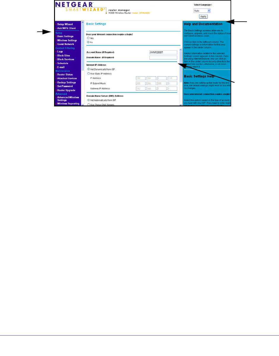
Router Interface
The router interface gives you access to the router’s current settings so you can view or
change them (if needed). The left column has the router menus, and the right column
provides online help. The middle column is the screen for the current menu option.
Router menus
(scroll to see
more)
Help for
the
current
screen
Current screen
Figure 1. Router menus, Basic Settings screen, and online help
• Setup Wizard. Specify the language, location, and automatically detect the Internet
connection.
• Add WPS Client. Add WPS-compatible wireless devices and other equipment to your
wireless network.
• Setup Menu. Set, upgrade, and check the ISP and wireless network settings of your
router.
• Content Filtering Menu. View and configure the router firewall settings to prevent
objectionable content from reaching your PCs.
• Maintenance Menu. Administer and maintain your router and network.
• Advanced Menu. Set the router up for unique situations such as when remote access by
IP or by domain name from the Internet is needed.
• Web Support. Go to the NETGEAR support site to get information, help, and product
documentation. These links work once you have an Internet connection.
20 | Chapter 2. Router Internet Setup
NETGEAR N300 Wireless Router with External Antennas WNR1500 User Manual
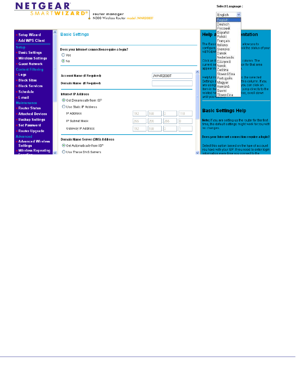
Select a Language for Your Screen Display
Using the Select Language drop-down menu, located in the upper right corner of the Router
Manager screen, you can display the router manager screens in any of languages shown in
Figure 2.
Figure 2. Select a Language
The language is set to English by default. The default language, as well as German, Russian,
and Portuguese are always stored in memory. When you select a language other than those
automatically stored in flash memory, if you are connected to the Internet at the time you
select it, that language is also stored in memory.
• If you are connected to the Internet and select a language that is not already stored in
flash memory, the language is downloaded from the NETGEAR server and stored in the
current language partition of flash memory.
• If you are not connected to the Internet when you select a language, you can only select
as the current language one of the languages that is stored in flash memory.
To specify a language to be used on your router manager screens, do the following:
1. Expand the list and select the language you want.
2. Click Apply.
The language you select is then downloaded and displayed in the language selection box,
and your screen display will be in the selected language.

Chapter 2. Router Internet Setup | 21
NETGEAR N300 Wireless Router with External Antennas WNR1500 User Manual
Note: If you are not connected to the Internet and select a language that is
not stored in flash memory, your selection may fail. If you see a
“download fails” message after your language selection, make sure
you are connected to the Internet and make your selection.
Setup Wizard
If you do not use the Smart Wizard on the Resource CD, you have to log in to the router to set
the country, language, and Internet connection.
Note: If you performed the NETGEAR Genie setup, the country, language,
Internet, and wireless network settings are already configured.
1. Select Setup Wizard from the top of the router menus.
2. Select either Yes or No, I want to configure the Router myself. If you select No, proceed
to Manual Setup (Basic Settings) on page 21.
3. If you selected Yes, click Next.
With automatic Internet detection, the Setup Wizard searches your Internet connection
for servers and protocols to determine your ISP configuration.
Manual Setup (Basic Settings)
The Basic Settings screen displays when you select No. I want to configure the Router
myself in the Setup Wizard and is also available from the router menus. It is where you view
or change ISP information. The fields that display vary depending on whether or not your
Internet connection requires a login.
1. Select Set Up > Basic Settings and select Yes or No depending on whether or not
your ISP requires a login. Figure 3, Basic Settings screen without (left) and with (right)
login. shows both forms of the Basic Settings screen.
• Yes. Select the encapsulation method and enter the login name. If you want to
change the login time-out, enter a new value in minutes.
• No. Enter the account and domain names, as needed.
2. Enter the settings for the IP address and DNS server.
3. If no login is required, you can specify the MAC Address setting.
4. Click Apply to save your settings.
5. Click Test to test your Internet connection. If the NETGEAR website does not appear within
1 minute, see Troubleshooting on page 85.
22 | Chapter 2. Router Internet Setup
NETGEAR N300 Wireless Router with External Antennas WNR1500 User Manual
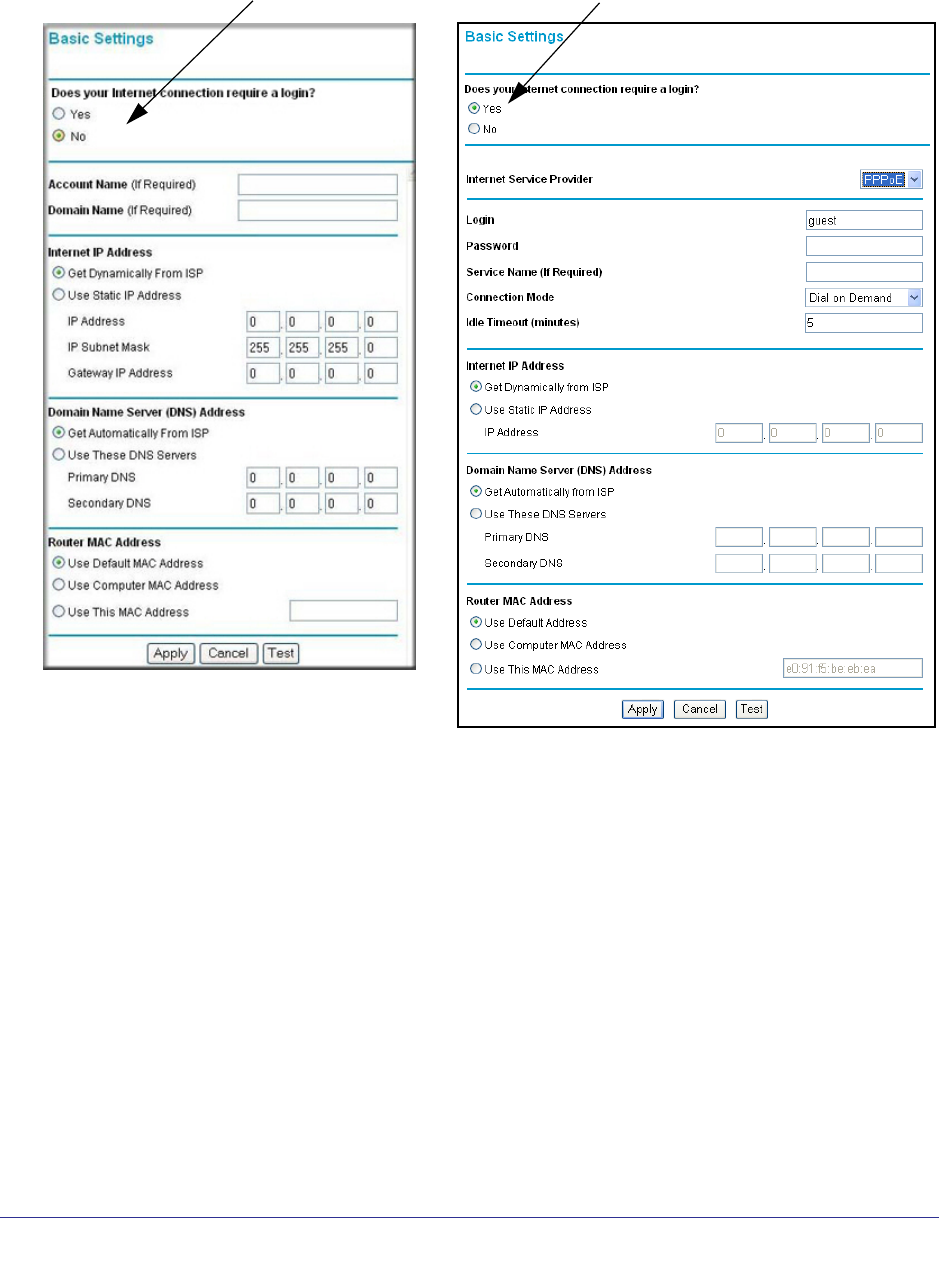
Basic Settings Screen
ISP does not require login ISP does require login
Figure 3. Basic Settings screen without (left) and with (right) login.
The following descriptions explain all the possible fields in the Basic Settings screen. Note
that which fields appear in this screen depends on whether or not an ISP login is required.
Does Your ISP Require a Login? Answer either yes or no.
• When no login is required, these fields display:
Account Name (If required). Enter the account name provided by your ISP. This might
also be called the host name.
Domain Name (If required). Enter the domain name provided by your ISP.
• When your ISP requires a login, these fields display:
Chapter 2. Router Internet Setup | 23
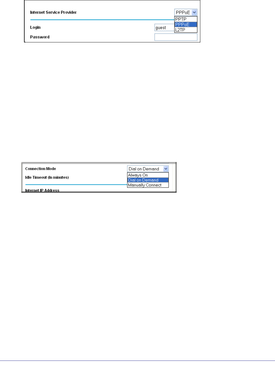
NETGEAR N300 Wireless Router with External Antennas WNR1500 User Manual
Internet Service Provider. This drop-down list contains a few ISPs that need special
protocols for connection.
The list includes:
-PPTP (Point to Point Tunneling Protocol), used primarily in Austrian DSL services.
-PPPoE (Point to Point Protocol over Ethernet), the protocol used by most DSL
services worldwide.
-L2TP (Layer 2 Tunneling Protocol), used to support virtual private networks (VPNs).
Login. The login name provided by your ISP. This is often an email address.
Password. The password that you use to log in to your ISP.
Service Name. If your connection is capable of connecting to multiple Internet services,
this setting specifies which service to use.
Connection Mode. You can use this drop-down list to select when the router connects to
and disconnect from the Internet.
The list includes:
-Always On. The router logs in to the Internet immediately after booting and never
disconnects.
-Dial on Demand. The router logs in only when outgoing traffic is present and logs out
after the idle time-out.
-Manually Connect. The router logs in or logs out only when the user clicks Connect
or Disconnect in the Router Status screen.
Idle Timeout (In minutes). If you want to change the login timeout, enter a new value in
minutes. This determines how long the router keeps the Internet connection active after
there is no Internet activity from the LAN. Entering a value of 0 (zero) means never log
out.
Internet IP Address
• When a login is required, these fields display:
Get Dynamically from ISP. Your ISP uses DHCP to assign your IP address. Your ISP
automatically assigns these addresses.

24 | Chapter 2. Router Internet Setup
NETGEAR N300 Wireless Router with External Antennas WNR1500 User Manual
Use Static IP Address. Enter the IP address, IP subnet mask, and the gateway IP
address that your ISP assigned. The gateway is the ISP’s router to which your router will
connect.
• When a login is not required, this field displays:
Use IP Over ATM (IPoA). Your ISP uses classical IP addresses (RFC 1577). Enter the IP
address, IP subnet mask, and gateway IP addresses that your ISP assigned.
Domain Name Server (DNS) Address. The DNS server is used to look up site addresses
based on their names.
Get Automatically from ISP. Your ISP uses DHCP to assign your DNS servers. Your ISP
automatically assigns this address.
Use These DNS Servers. If you know that your ISP does not automatically transmit DNS
addresses to the router during login, select this option, and enter the IP address of your
ISP’s primary DNS server. If a secondary DNS server address is available, enter it also.
NAT (Network Address Translation). NAT automatically assigns private IP addresses
(10.1.1.x) to LAN-connected devices.
Enable. Usually NAT is enabled.
Disable. This disables NAT, but leaves the firewall active. Disable NAT only if you are
sure you do not need it. When NAT is disabled, only standard routing is performed by this
router. Classical routing lets you directly manage the IP addresses that the router uses.
Classical routing should be selected only by experienced users.1
Disable firewall. This disables the firewall in addition to disabling NAT. With the firewall
disabled, the protections usually provided to your network are disabled.
When no login is required, this field displays:
Router MAC Address. The Ethernet MAC address used by the router on the Internet port.
Some ISPs register the MAC address of the network interface card in your computer when
your account is first opened. They will then accept traffic only from the MAC address of that
computer. This feature allows your router to use your computer’s MAC address (this is also
called cloning).
Use Default Address. Use the default MAC address.
Use Computer MAC Address. The router captures and uses the MAC address of the
computer that you are now using. This has to be the computer that is allowed by the ISP.
Use This MAC Address. Enter the MAC address that you want to use.
Unsuccessful Internet Connection
1. Review your settings to be sure you have selected the correct options and typed
everything correctly.
1. Disabling NAT reboots the router and resets its settings to the factory defaults. Disable NAT only if you plan to set
up the router in a setting where you will be manually administering the IP address space on the LAN side of the router.
Chapter 2. Router Internet Setup | 25
NETGEAR N300 Wireless Router with External Antennas WNR1500 User Manual
2. Contact your ISP to verify that you have the correct configuration information.
3. Read Chapter 7, Troubleshooting. If problems persist, register your NETGEAR product and
contact NETGEAR Technical Support.
Note: If you cannot connect to the wireless router, check the Internet
Protocol (TCP/IP) properties in the Network Connections section of
your PC Control Panel. They should be set to obtain both IP and
DNS server addresses automatically.
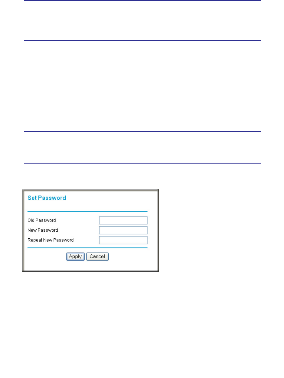
Change Password
For security reasons, the router has its own user name and password that default to admin
and password. You can and should change these to a secure user name and password that
are easy to remember. The ideal password contains no dictionary words from any language
and is a mixture of upper case and lower case letters, numbers, and symbols. It can be up to
30 characters.
Note: The router user name and password are not the same as the user
name and password for logging in to your Internet connection. See
Types of Logins on page 26 for more information about login types.
1. Select Maintenance > Set Password to display the following screen:.
2. Enter the old password.
3. Enter the new password twice.
4. Click Apply to save your changes.
After changing the password, you are required to log in again to continue the
configuration. If you have backed up the router settings previously, you should do a new
backup so that the saved settings file includes the new password. See Back Up on
page 56 for information about backing up your network configuration.

26 | Chapter 2. Router Internet Setup
NETGEAR N300 Wireless Router with External Antennas WNR1500 User Manual
Log Out Manually
The router interface provides a Logout command at the bottom of the router menus. Log out
when you expect to be away from your computer for a relatively long period of time.
Types of Logins
There are three separate types of logins that have different purposes. It is important that you
understand the difference so that you know which login to use when.
• Router login logs you in to the router interface. See Log In to the Router on page 17 for
details about this login.
• ISP login logs you in to your Internet service. Your service provider has provided you with
this login information in a letter or some other way. If you cannot find this login
information, contact your service provider.
• Wi-Fi network name and passphrase logs you in to your wireless network. See Chapter
3, Wireless Settings for more information.

Chapter 3. Wireless Settings | 27
3
3. Wireless Settings
Protecting your network
This chapter describes how to use the Wireless Settings screens to view and change (if needed)
your wireless network settings. Security features to prevent objectionable content from reaching
your PCs are covered in Chapter 4, Content Filtering.
This chapter includes the following sections:
• Security Basics
• Add Clients (Computers or Devices) to Your Network Wireless Settings
• Wireless Settings
• Add Guest Networks

28 | Chapter 3. Wireless Settings
NETGEAR N300 Wireless Router with External Antennas WNR1500 User Manual
Security Basics
Unlike wired network data, wireless data transmissions extend beyond your walls and can be
received by any device with a compatible wireless adapter (radio). For this reason, it is very
important to maintain the preset security and understand the other security features available
to you. Besides the preset security settings described above, your router has the security
features described here and in Chapter 4, Content Filtering.
• Turn off wireless connectivity
• Disable SSID broadcast
• Restrict access by MAC address
• Wireless security options
Turn Off Wireless Connectivity
You can completely turn off the wireless connectivity of the router. For example, if you use
your notebook computer to wirelessly connect to your router and you take a business trip,
you can turn off the wireless portion of the modem router while you are traveling. Other
members of your household who use computers connected to the router through Ethernet
cables can still use the router.
Disable SSID Broadcast
By default, the router broadcasts its Wi-Fi network name (SSID) so devices can find it. If you
change this setting to not allow the broadcast, wireless devices do not find your router unless
they are configured with the same SSID.
Note: Turning off SSID broadcast nullifies the wireless network discovery
feature of some products such as Windows XP, but the data is still
fully exposed to a determined snoop using specialized test
equipment like wireless sniffers. If you allow the broadcast, be sure
to keep wireless security enabled.
Restrict Access by MAC Address
You can enhance your network security by allowing access to only specific PCs based on
their Media Access Control (MAC) addresses. You can restrict access to only trusted PCs so
that unknown PCs cannot wirelessly connect to the router. MAC address filtering adds
additional security protection to the wireless security option you have in force. The Wireless
Station Access List determines which wireless hardware devices are allowed to connect to
the router by MAC address. See Restrict Access by MAC Address on page 28 for the
procedure.

Chapter 3. Wireless Settings | 29
NETGEAR N300 Wireless Router with External Antennas WNR1500 User Manual
Wireless Security Options
A security option is the type of security protocol applied to your wireless network. The
security protocol in force encrypts data transmissions and ensures that only trusted devices
receive authorization to connect to your network. There are two types of encryption: Wired
Equivalent Privacy (WEP) and Wi-Fi Protected Access (WPA). WPA is stronger, and
therefore, recommended over WEP. WPA has several options including pre-shared key
(PSK) encryption.
This section presents an overview of the security options and provides guidance on when to
use which option. Note that it is also possible to disable wireless security. NETGEAR does
not recommend this.
WPA Encryption
WPA encryption is built into all hardware that has the Wi-Fi-certified seal. This seal means
the product is authorized by the Wi-Fi Alliance (http://www.wi-fi.org/) because it complies with
the worldwide single standard for high-speed wireless local area networking.
• WPA2-PSK is the strongest. It is advertised to be theoretically indecipherable due to the
greater degree of randomness in encryption keys that it generates. WPA2-PSK gets
higher speed because it is usually implemented through hardware, while WPA-PSK is
usually implemented through software. WPA2-PSK uses a passphrase to authenticate
and generate the initial data encryption keys. Then it dynamically varies the encryption
key.
• WPS-PSK + WPA2-PSK Mixed Mode provides broader support for all wireless clients.
WPA2-PSK clients get higher speed and security, and WPA-PSK clients get decent
speed and security. The product documentation for your wireless adapter and WPA client
software should have instructions about configuring their WPA settings.
WPA-PSK uses a passphrase to perform the authentication and generate the initial data
encryption keys. Then it dynamically varies the encryption key. WPA-PSK uses Temporal
Key Integrity Protocol (TKIP) data encryption, implements most of the IEEE 802.11i
standard, and is designed to work with all wireless network interface cards, but not all
wireless access points. It is superseded by WPA2-PSK.
WEP Encryption
WEP uses an old encryption method and can be easily decoded with today's powerful
computers. Use this mode only when you have a very old legacy wireless client that does not
support WPA-PSK. WEP is only available with certain Mode settings. The Wi-Fi alliance
highly recommends against using WEP and plans to make it obsolete.

30 | Chapter 3. Wireless Settings
NETGEAR N300 Wireless Router with External Antennas WNR1500 User Manual
Add Clients (Computers or Devices) to Your Network
Choose either the manual or the WPS method to add wireless computers or devices to your
wireless network.
Manual Method
1. Open the software that manages your wireless connections on the wireless device
(laptop computer, gaming device, iPhone) that you want to connect to your router. This
software scans for all wireless networks in your area.
2. Look for your network and select it.If you did not change the name of your network during
the setup process, look for the default Wi-Fi network name (SSID) and select it. The default
Wi-Fi network name (SSID) is located on the product label on the bottom of the router.
3. When prompted, enter the passphrase (password) to join the wireless network. This is the
password that you set up in the Wireless Settings screen in the Security Options section.
4. Repeat steps 1–3 to add other wireless devices.
Wi-Fi Protected Setup (WPS) Method
Wi-Fi Protected Setup (WPS) is a standard that lets you easily join a secure wireless network
with WPA or WPA2 wireless security. The router automatically sets security for each
computer or device that uses WPS to join the wireless network. To use WPS, make sure that
your wireless devices are Wi-Fi certified and support WPS. NETGEAR products that use
WPS call it Push 'N' Connect.1
Note: If the wireless network name (SSID) changes each time you add a
WPS client, the Keep Existing Wireless Settings check box on the
Advanced Wireless Settings screen has been cleared. See
Advanced Wireless Settings on page 70 for more information about
this setting.
You can use a WPS button or the router interface method to add wireless computers and
devices to your wireless network.
WPS Button Method
1. Press the WPS button on the rear panel of the router.
2. Within 2 minutes, press the WPS button on your wireless computer or device, or follow the
WPS instructions that came with the computer. The device is now connected to your router.
3. Repeat steps 1–2 to add other WPS wireless computers or devices.
1. For a list of other Wi-Fi-certified products available from NETGEAR, go to http://www.wi-fi.org.
Chapter 3. Wireless Settings | 31
NETGEAR N300 Wireless Router with External Antennas WNR1500 User Manual
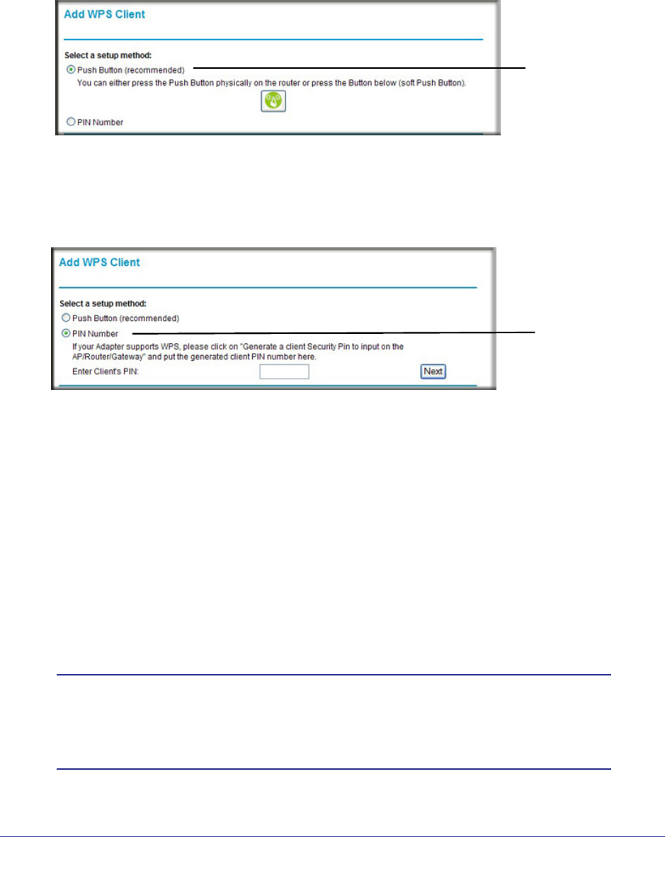
Router Interface Method
1. Select Add WPS Client at the top of the router menus.
2. Click Next. The following screen lets you select the method for adding the WPS client.
WPS Push
button method
3. Select either Push Button or PIN Number. With either method, the router tries to
communicate with the computer or wireless device, set the wireless security for wireless
device, and allow it to join the wireless network.
The PIN method displays this screen so you can enter the client security PIN number:
WPS PIN method
While the router attempts to connect, the WPS LED on the front of the router blinks
green. When the router establishes a WPS connection, the LED is solid green and the
router WPS screen displays a confirmation message.
4. Repeat to add another WPS client to your network.
Wireless Settings
The Wireless Settings screen lets you view or change the wireless network settings. Note
that your preset router has a unique network name and password, located on the product
label. NETGEAR recommends that you use these settings. If you decide to change them,
note the new settings and save them in a secure location.
Note: If you use a wireless computer to change the wireless network
name (SSID) or security options, you are disconnected when you
click Apply. To avoid this problem, use a computer with a wired
connection to access the router.
32 | Chapter 3. Wireless Settings
NETGEAR N300 Wireless Router with External Antennas WNR1500 User Manual
Consider Every Device on Your Network
Before you begin, check the following:
• Every wireless computer has to be able to obtain an IP address by DHCP from the router
as described in Use Standard TCP/IP Properties for DHCP on page 16.
• Each computer or wireless adapter in your network must have the same SSID and
wireless mode (bandwidth/data rate) as the router. Check that the wireless adapter on
each computer can support the mode and security option you want to use.
• The security option on each wireless device in the network must match the router. For
example, if you select a security option that requires a passphrase, be sure to use same
passphrase for each wireless computer in the network.
View or Change Wireless Settings
NETGEAR recommends that you use wireless security to protect your network from
unwanted access and that you change the default network name of NETGEAR to a name
that you can easily recognize when connecting wirelessly to the router. You view or change
these settings in the Wireless Settings screen.
To view or change wireless settings:
1. Select Setup > Wireless Settings. The Wireless Settings screen displays.
2. Make any changes that are needed, and click Apply when done to save your settings.

Chapter 3. Wireless Settings | 33
NETGEAR N300 Wireless Router with External Antennas WNR1500 User Manual
Note: The screen sections, settings, and procedures are explained in the
following sections.
3. Set up and test your computers for wireless connectivity:
a. Use your wireless computer or device to join your network. When prompted, enter the
network password.
b. From the wirelessly connected computer, make sure that you can access the
Internet.
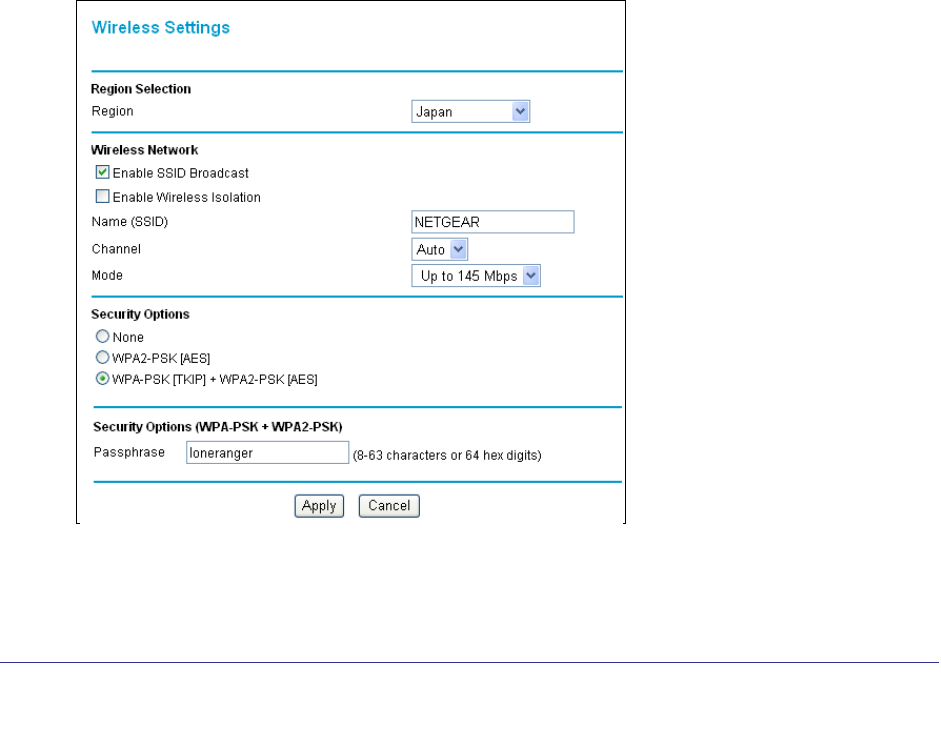
Wireless Settings Screen Fields
Region
• This field identifies the region where the WNR1500 router can be used. It might not be
legal to operate the wireless features of the router in a region other than one of those
identified in this field. In North America, the region cannot be changed, and is set by
default to US.
Wireless Network
• Allow Broadcast of Name (SSID). This setting allows the router to broadcast its SSID so
that a wireless station can display this wireless name (SSID) in its scanned network list.
This check box is selected by default. To turn off the SSID broadcast, clear the Allow
Broadcast of Name (SSID) check box and click Apply.
• Wireless Isolation. When this check box is selected, wireless stations cannot
communicate with each other or with stations on the wired network. By default, this check
box is not selected.
• Name (SSID). The SSID is also known as the wireless network name. Enter a value of up
to 32 alphanumeric characters. When more than one wireless network is active, different
wireless network names provide a way to separate the traffic. For a wireless device to
participate in a particular wireless network, it must be configured with the SSID for that
network. The WNR1500 default SSID is NETGEAR. You can disable this broadcast as
described in Click Apply to save your settings. on page 36.
• Channel. This field determines which operating frequency is used. It should not be
necessary to change the wireless channel unless you notice interference problems with
another nearby wireless network. The router uses channel bonding technology to extend
the bandwidth for data transmission.
• Mode. This field determines which data communications protocol is used. You can
choose from:
-Up To 54 Mbps. Legacy mode, for compatibility with the slower 802.11b and 802.11g
wireless devices. WEP and WPA security options are supported at 54 Mbps only.
-Up To 145 Mbps. Neighbor friendly mode, for reduced interference with neighboring
wireless networks. Provides two transmission streams with different data on the same

34 | Chapter 3. Wireless Settings
NETGEAR N300 Wireless Router with External Antennas WNR1500 User Manual
channel at the same time, but also allows 802.11b and 802.11g wireless devices. This
is the default mode.
-Up To 300 Mbps. Performance mode, using channel expansion to achieve the 300
Mbps data rate. The WNR1500 router uses the channel you selected as the primary
channel and expands to the secondary channel (primary channel +4 or –4) to achieve
a 40 MHz frame-by-frame bandwidth. The router detects channel usage and disables
frame-by-frame expansion if the expansion would result in interference with the data
transmission of other access points or clients.
Note: The maximum wireless signal rate is derived from the IEEE
Standard 802.11 specifications. Actual data throughput can vary.
Network conditions and environmental factors, including volume of
network traffic, building materials and construction, and network
overhead, lower actual data throughput rate.
• Security Options. The selection of wireless security options can significantly affect your
network performance. The time it takes to establish a wireless connection can vary
depending on both your security settings and router placement.
Set Up WPA-PSK and WPA2-PSK Wireless Security
WPA–Pre-Shared Key performs authentication. WPA-PSK uses TKIP (Temporal Key Integrity
Protocol) data encryption, and WPA2-PSK uses AES (Advanced Encryption Standard) data
encryption. Both methods dynamically change the encryption keys making them nearly
impossible to circumvent.
Mixed mode allows clients using either WPA-PSK (TKIP) or WPA2-PSK (AES). This provides
the most reliable security, and is easiest to implement, but it might not be compatible with
older adapters.
Note: To display the security options WPA-PSK and WEP, you have to use
the legacy mode setting of Up to 54 Mpbs.
To set up WPA2 or WPA:
1. Select Setup > Wireless Settings. The Wireless Settings screen displays.
2. Select a radio button for the security option that you want to use. Mixed mode (WPA-PSK
[TKIP] + WP2-PSK [AES]) is the most flexible, since it allows clients using either WPA-PSK
or WPA2-PSK.
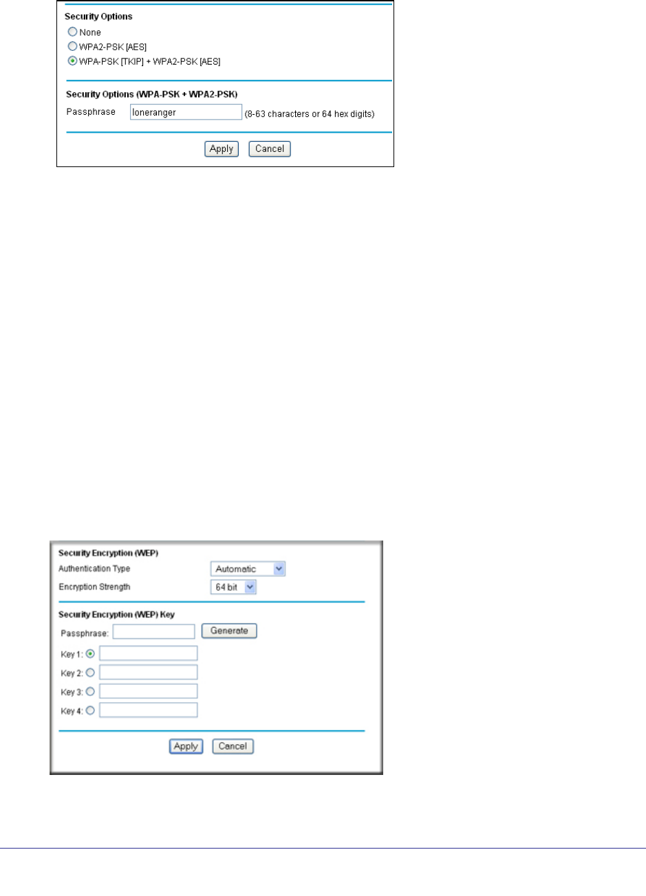
Chapter 3. Wireless Settings | 35
NETGEAR N300 Wireless Router with External Antennas WNR1500 User Manual
3. In the Passphrase field, enter a word or group of 8–63 printable characters. The
passphrase is case-sensitive.
4. Click Apply to save your settings.
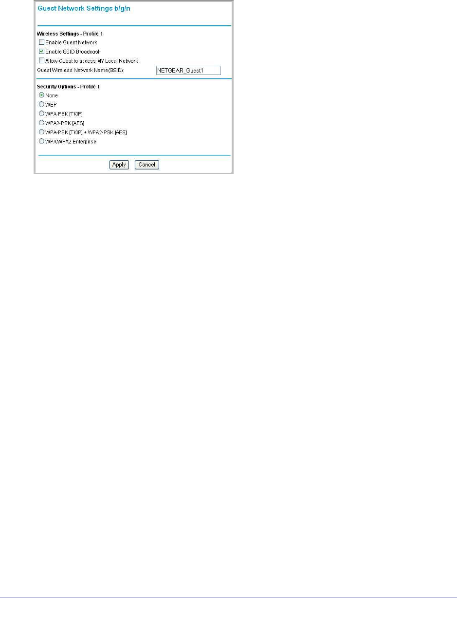
Set Up WEP Wireless Security
WEP Shared Key authentication and WEP data encryption can be defeated by a determined
eavesdropper using publicly available tools.
To set up WEP data encryption:
If you use a wireless computer to setup WEP, you will be disconnected when you click Apply.
You can rejoin the network with its new security settings or use a wired connection to make
further changes. router. Not all wireless devices support passphrases. If yours does not, then
you will need to manually enter the WEP key in order to join the wireless network.
1. Select Setup > Wireless Settings.
2. In the Mode field, select the legacy mode setting of Up to 54 Mpbs.
The WEP and WPA radio buttons display in the Security Options section of the screen.
3. Select the WEP radio button and the screen expands as shown in the following figure:
.
4. Select the authentication type and encryption strength.

36 | Chapter 3. Wireless Settings
NETGEAR N300 Wireless Router with External Antennas WNR1500 User Manual
5. You can manually or automatically program the four data encryption keys. These values
must be identical on all computers and access points in your network.
• Automatically Generate. In the Passphrase field, enter a word or group of printable
characters, and click Generate. The passphrase is case-sensitive. For example,
NETGEAR is not the same as nETgear. The four key fields are automatically
populated with key values.
• Manual. Enter 10 hexadecimal digits (any combination of 0–9, a–f, or A–F). These
entries are not case-sensitive. For example, AA is the same as aa. Select which of the
four keys to activate.
6. Click Apply to save your settings.
WEP Security Encryption Fields
• Automatic. With the Automatic option, the router tries both Open System and Shared
Key authentication. Usually, this setting works fine. If it fails, select Open System or
Shared Key. You can also refer to your wireless adapter’s documentation to see what
method to use.
• Open System. With Open System authentication and 64 or 128 bit WEP data encryption,
the router performs data encryption but does not perform any authentication. Anyone can
join the network. This setting provides very little practical wireless security.
• Shared Key. A wireless device must know the WEP key to join the network. Select the
encryption strength (64 or 128 bit data encryption). Manually enter the key values, or
enter a word or group of printable characters in the Passphrase field. Manually entered
keys are not case-sensitive, but passphrase characters are case-sensitive.
Add Guest Networks
Adding a guest network allows visitors at your home to use the Internet without having to
know your wireless security key. The JWNR2000T router supports three guest networks.
To add a guest network, do the following:
Chapter 3. Wireless Settings | 37
NETGEAR N300 Wireless Router with External Antennas WNR1500 User Manual
1. Select Guest Network from the Setup menu. The Guest Network Settings screen
appears.
2. Select any of the following Wireless settings:
• Enable Guest Network – When this check box is selected, the guest network is enabled,
and guests can connect to your network using the SSID of this profile.
• Enable SSID Broadcast – If selected, the Wireless Access Point broadcasts its name
(SSID) to all Wireless Stations. Stations with no SSID can adopt the correct SSID for
connections to this Access Point.
• Allow Guest to access MY Local Network – If selected any user who connects to this
SSID can access local networks associated with the router like users in the primary SSID.
3. Give the wireless network a name.
4. The name is case-sensitive and can be up to 32 characters. The same name must be
assigned to all wireless devices in your network. NETGEAR recommends that you
change the name to a different value.
5. Select a Security option from the list.
6. Click Apply to save your selections.
Figure 3-1

Chapter 4. Content Filtering | 38
4
4. Content Filtering
This chapter explains how to use the basic firewall features of the router to prevent objectionable
content from reaching the PCs and other devices connected to your network.
This chapter includes the following sections:
• Live Parental Controls
• Keyword Blocking of HTTP Traffic
• Block Outbound Traffic to Internet Services
• Set the Time Zone
• Schedule Blocking
• Enable Security Event Email Notification
• View Logs of Web Access or Attempted Web Access
• Allow Inbound Connections to Your Network
• Port Forwarding to a Local Server
• Port Triggering
Chapter 4. Content Filtering | 39
NETGEAR N300 Wireless Router with External Antennas WNR1500 User Manual
Live Parental Controls
NETGEAR Live Parental Controls, powered by OpenDNS, is a router-based Web filtering
solution available on NETGEAR N300 Wireless router and gateway products. Designed to
protect you from identity theft and scams, Live Parental Controls blocks up to 50 categories
of Internet content.
Live Parental Controls protects all Internet-connected devices through the router. It protects
not only computers, but also set-top boxes, iPhones, iPods, and gaming consoles that are
attached to your network. Default and per-user settings allow you to customize configurations
for different computing arrangements and personalize the settings for each person. Per-time
settings allow Internet access during scheduled time slots.
Live Parental Controls requires a one-time installation of the management utility. Once set
up, Live Parental Controls runs in the background and does not interfere with normal Internet
usage.
Download Live Parental Controls from this website: http://www.netgear.com/lpc.
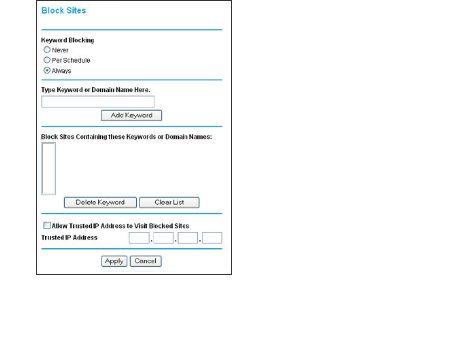
Keyword Blocking of HTTP Traffic
Use keyword blocking to prevent certain types of HTTP traffic from accessing your network.
The blocking can be always or according to a scheduled.
1. Select Security > Block Sites.

40 | Chapter 4. Content Filtering
NETGEAR N300 Wireless Router with External Antennas WNR1500 User Manual
2. Select one of the keyword blocking options:
• Per Schedule. Turn on keyword blocking according to the Schedule screen settings.
• Always. Turn on keyword blocking all the time, independent of the Schedule screen.
3. In the Keyword field, enter a keyword or domain, click Add Keyword, and click Apply.
The Keyword list. supports up to 32 entries. Here are some sample entries:
• Specify XXX to block http://www.badstuff.com/xxx.html
• Specify .com if you want to allow only sites with domain suffixes such as .edu or .gov
• Enter a period (.) to block all Internet browsing access
Delete a Keyword or Domain
1. Select the keyword you want to delete from the list.
2. Click Delete Keyword and click Apply to save your changes.
Specify a Trusted Computer
You can exempt one trusted computer from blocking and logging. That computer has to be
configured to use a a fixed IP address.
1. In the Trusted IP Address field, enter the IP address.
2. Click Apply to save your changes.
Block Outbound Traffic to Internet Services
The router lets you block computers on your local network from using certain Internet
services. This is called service blocking or port filtering. You can block Internet access from a
local computer based on local computer, Internet site being contacted, time of day, and type
of service being requested.
Chapter 4. Content Filtering | 41
NETGEAR N300 Wireless Router with External Antennas WNR1500 User Manual
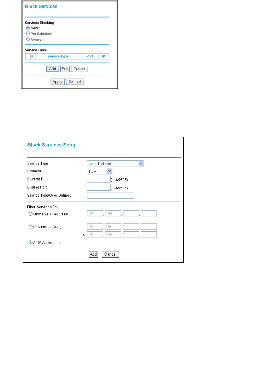
To block access to Internet services:
1. Select Content Filtering > Block Services. The Block Services screen displays.
2. Enable service blocking by selecting either Per Schedule or Always, and then click Apply.
To block by schedule, be sure to specify a time period in the Schedule screen. For
information about scheduling, see Schedule Blocking on page 43.
3. Specify a service for blocking by clicking Add. The Block Services Setup screen displays.
4. From the Service Type list, select the application or service to be allowed or blocked.
5. If you do not see the service or application that you want to block in the list, select User
Defined.
To define a service or application, you need to know which port number or range of
numbers it uses. The service port numbers for many common protocols are defined by
the Internet Engineering Task Force (IETF) and published in RFC1700, “Assigned
Numbers.” Service numbers for other applications are typically chosen from the range
1024 to 65535 by the authors of the application. You can often determine port number
42 | Chapter 4. Content Filtering
NETGEAR N300 Wireless Router with External Antennas WNR1500 User Manual
information by contacting the publisher of the application, by asking user groups or
newsgroups, or by searching.
-Enter the starting port and ending port numbers. If the application uses a single port
number, enter that number in both fields.
-If you know that the application uses either TCP or UDP, select the appropriate
protocol. If you are not sure, select Both.
6. Select the radio button for the IP address configuration you want to block, and then enter the
IP addresses in the appropriate fields.
7. Click Add to enable your Block Services Setup selections.
Block Services by IP Address Range
In the Filter Services For area, you can block the specified service for a single computer, a
range of computers (having consecutive IP addresses), or all computers on your network.
Set the Time Zone
The router uses the Network Time Protocol (NTP) to obtain the current time and date from
one of several network time servers on the Internet. You can check and set (if needed) the
time zone to ensure time stamps match your local time.
1. Select Security > Schedule to display the following screen:
Chapter 4. Content Filtering | 43
NETGEAR N300 Wireless Router with External Antennas WNR1500 User Manual
2. Select your time zone. This setting determines the blocking schedule and time-stamping of
log entries.
3. If your time zone is in daylight savings time, select the Adjust for Daylight Savings Time
check box to add one hour to standard time.
If your region uses daylight savings time, select Adjust for Daylight Savings Time on
the first day and clear it after the last day.
4. The router has a list of NETGEAR NTP servers. If you would prefer to use a particular NTP
server as the primary server, select the Use this NTP Server check box, and enter its IP
address.
5. Click Apply to save your settings.
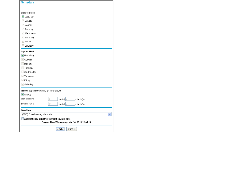
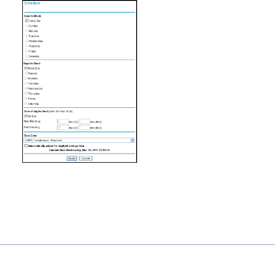
Schedule Blocking
You can set up a schedule for when blocking occurs or when access is not restricted.
1. Select Security > Schedule to display the following screen:
2. To block Internet services based on a schedule, select Every Day or select one or more
days. If you want to limit access completely for the selected days, select All Day. Otherwise,
to limit access during certain times for the selected days, enter times in the Start Time and
End Time fields.
• Enter the values in 24-hour time format. For example, 10:30 a.m. is 10 hours and 30
minutes, and 10:30 p.m. is 22 hours and 30 minutes.
• If you set the start time after the end time, the schedule is effective through midnight
the next day.
44 | Chapter 4. Content Filtering
NETGEAR N300 Wireless Router with External Antennas WNR1500 User Manual
3. Click Apply to save your settings.
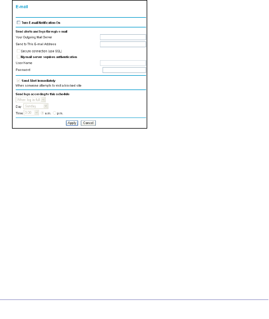
Enable Security Event Email Notification
To receive logs and alerts by email, provide your email information in the E-mail screen and
specify which alerts you want to receive and how often.
Select Security > Email to display the following screen:
Fill in the fields as follows:
Turn Email Notification On. Select this check box if you want to receive email logs and
alerts from the router.
Your Outgoing Mail Server. Enter the name or IP address of your ISP’s outgoing (SMTP)
mail server (such as mail.myISP.com). You might be able to find this information in the
configuration settings of your email program. Enter the email address to which logs and alerts
are sent. This email address is also used as the From address. If you leave this field blank,
log and alert messages are not sent by email.
Send to This E-mail Address. Enter the email address where you want logs and alerts sent.
This email address is also used as the From address. If you leave this field blank, log and
alert messages are not sent by email.
My mail server requires authentication. If you use an outgoing mail server provided by
your current ISP, you do not need to select this field. If you use an email account that is not
provided by your ISP, select this field, and enter the required user name and password
information.

Chapter 4. Content Filtering | 45
NETGEAR N300 Wireless Router with External Antennas WNR1500 User Manual
Send Alert Immediately. Select the corresponding check box if you would like immediate
notification of a significant security event, such as a known attack, port scan, or attempted
access to a blocked site.
Send logs according to this schedule. Specifies how often to send the logs: Hourly, Daily,
Weekly, or When Full.
Day for sending logs specifies which day of the week to send the log. This is relevant
when the log is sent weekly.
Time for sending log specifies the time of day to send the log. This is relevant when the
log is sent daily or weekly.
Note: If the Weekly, Daily, or Hourly option is selected and the log fills up
before the specified period, the log is automatically emailed to the
specified email address. After the log is sent, it is cleared from the
router’s memory. If the router cannot email the log file, the log buffer
might fill up. In this case, the router overwrites the log and discards
its contents.
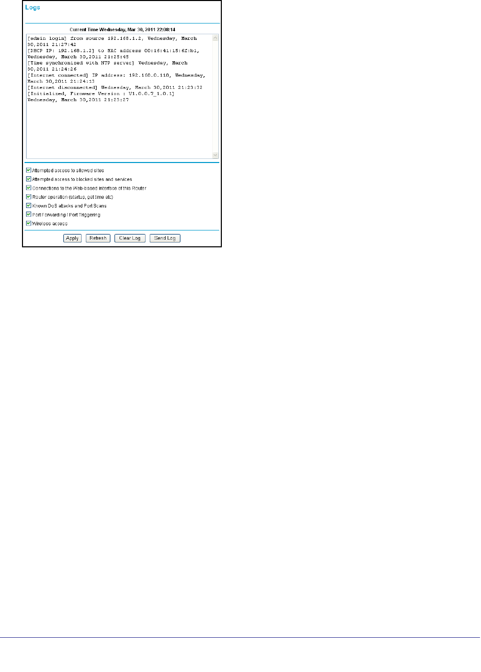
View Logs of Web Access or Attempted Web Access
The log is a detailed record of the websites you have accessed or attempted to access. Up to
128
entries are stored in the log. Log entries appear only when keyword blocking is enabled
and no log entries are made for the trusted user.
46 | Chapter 4. Content Filtering
NETGEAR N300 Wireless Router with External Antennas WNR1500 User Manual
Select Content Filtering > Logs. The Logs screen displays.
• Date and time. The date and time the log entry was recorded.
• Source IP. The IP address of the initiating device for this log entry.
• Target address.The name or IP address of the website or newsgroup visited or to which
access was attempted.
• Action. Whether the access was blocked or allowed.
If you change the check box selections, click Apply so that your changes take effect. You can
select as many or as few of these items as you wish.
To refresh the log screen, click the Refresh button.
To clear the log entries, click the Clear Log button.
To e-mail the log immediately, click the Send Log button.
Allow Inbound Connections to Your Network
By default, the WNR1500 router blocks any inbound traffic from the Internet to your
computers except for replies to your outbound traffic. However, you might need to create
exceptions to this rule for the following purposes:
• To allow remote computers on the Internet to access a server on your local network.
• To allow certain applications and games to work correctly when their replies are not
recognized by your router.
Your router provides two features for creating these exceptions: port forwarding and port
triggering.

Chapter 4. Content Filtering | 47
NETGEAR N300 Wireless Router with External Antennas WNR1500 User Manual
• Port forwarding. You can use this feature to allow certain types of incoming traffic to
reach servers on your local network. For example, you might make a local Web server,
FTP server, or game server visible and available to the Internet.
• Port triggering. Port triggering is a dynamic extension of port forwarding that is useful in
these cases:
-More than one local computer needs port forwarding for the same application (but not
simultaneously).
-An application needs to open incoming ports that are different from the outgoing port.
Port forwarding and port triggering are described in the following sections.
Port Forwarding to a Local Server
Using the port forwarding feature, you can allow certain types of incoming traffic to reach
servers on your local network. For example, you might make a local Web server, FTP server,
or game server visible and available to the Internet.
Use the Port Forwarding screen to configure the router to forward specific incoming protocols
to computers on your local network. In addition to servers for specific applications, you can
also specify a default DMZ server to which all other incoming protocols are forwarded. The
DMZ server is configured in the WAN Setup screen, as discussed in Set Up a Default DMZ
Server on page 65.
Before starting, you need to determine which type of service, application, or game you will
provide, and the local IP address of the computer that will provide the service. Be sure the
computer’s IP address never changes.
Tip: To ensure that your server computer always has the same IP address,
use the reserved IP address feature of your WNR1500 router. See
Reserved IP Addresses Setup on page 69 for instructions on how to use
reserved IP addresses.
48 | Chapter 4. Content Filtering
NETGEAR N300 Wireless Router with External Antennas WNR1500 User Manual
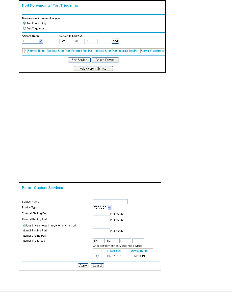
To set up port forwarding to a local server:
1. Select Advanced > Port Forwarding/Port Triggering. The Port Forwarding/Port
Triggering screen displays:
2. From the Service Name list, select the service or game that you will host on your network. If
the service does not appear in the list, see the following section, Add a Custom Service .
3. In the corresponding Server IP Address fields, enter the last digit of the IP address of your
local computer that will provide this service.
4. To the right of Server IP Address, click Add. The service appears in the list in the screen.
Add a Custom Service
To define a service, game, or application that does not appear in the Service Name list, you
must first determine which port number or range of numbers is used by the application. You
can usually determine this information by contacting the publisher of the application or user
groups or newsgroups. When you have the port number information, follow these steps:
1. Select Advanced > Port Forwarding/Port Triggering and then click Add Custom
Service. The Ports–Custom Services screen displays.
2. In the Service Name field, enter a descriptive name.
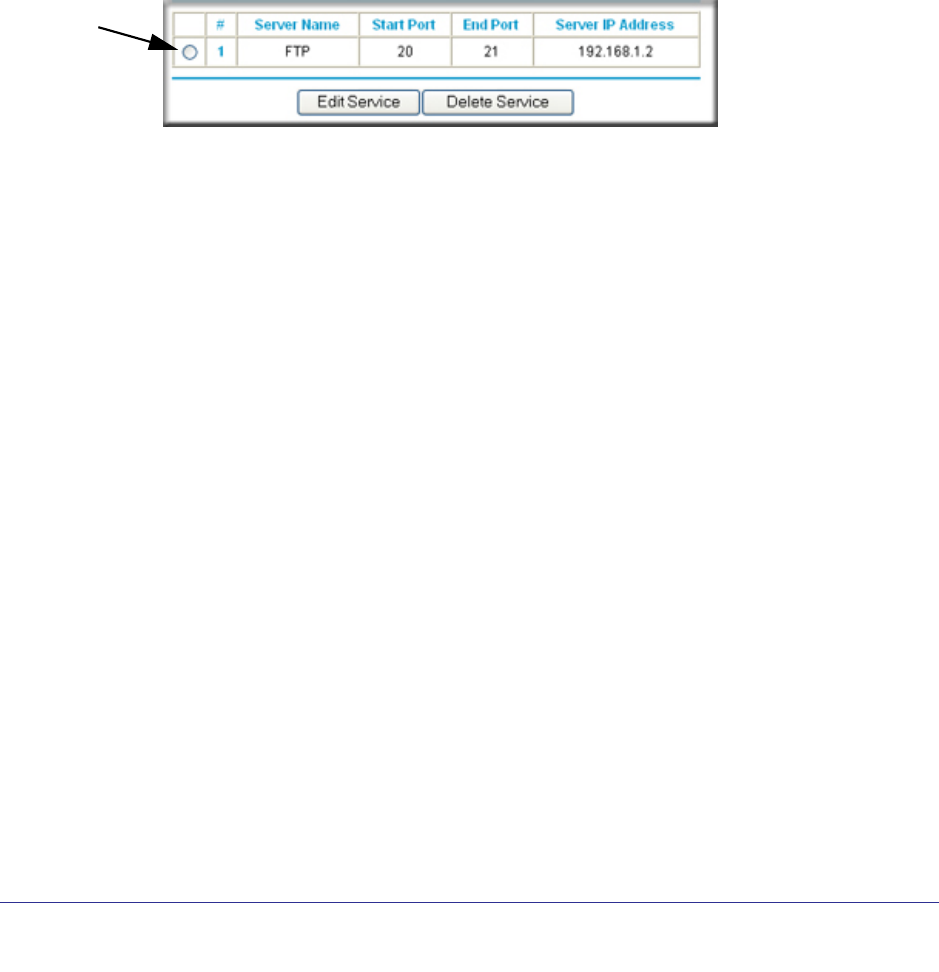
Chapter 4. Content Filtering | 49
NETGEAR N300 Wireless Router with External Antennas WNR1500 User Manual
3. In the Service Type field, select the protocol. If you are unsure, select TCP/UDP.
4. In the Starting Port field, enter the beginning port number.
• If the application uses only a single port, enter the same port number in the Ending Port
field.
• If the application uses a range of ports, enter the ending port number of the range in the
Ending Port field.
5. In the Server IP Address field, enter the IP address of your local computer that will provide
this service.
6. Click Apply. The service appears in the list in the Port Forwarding/Port Triggering screen.
Edit or Delete a Port Forwarding Entry
1. In the table, select the button next to the service name.
2. Click Edit Service or Delete Service to make changes.
3. Click Apply.
Application Example: Making a Local Web Server Public
If you host a Web server on your local network, you can use port forwarding to allow Web
requests from anyone on the Internet to reach your Web server.
To make a local Web server public:
1. Assign your Web server either a fixed IP address or a dynamic IP address using DHCP
address reservation, as explained in Use the Router as a DHCP Server on page 68. In
this example, your router will always give your Web server an IP address of
192.168.1.33.
2. In the Port Forwarding screen, configure the router to forward the HTTP service to the local
address of your Web server at 192.168.1.33.
HTTP (port 80) is the standard protocol for Web servers.
3. (Optional) Register a host name with a Dynamic DNS service, and configure your router to
use the name as described in Dynamic DNS on page 65.
To access your Web server from the Internet, a remote user must know the IP address that
has been assigned by your ISP. However, if you use a Dynamic DNS service, the remote
user can reach your server by a user-friendly Internet name, such as mynetgear.dyndns.org.

50 | Chapter 4. Content Filtering
NETGEAR N300 Wireless Router with External Antennas WNR1500 User Manual
Port Triggering
Port triggering is a dynamic extension of port forwarding that is useful in these cases:
• More than one local computer needs port forwarding for the same application (but not
simultaneously).
• An application needs to open incoming ports that are different from the outgoing port.
When port triggering is enabled, the router monitors outbound traffic looking for a specified
outbound “trigger” port. When the router detects outbound traffic on that port, it remembers
the IP address of the local computer that sent the data. The router then temporarily opens the
specified incoming port or ports, and forwards incoming traffic on the triggered ports to the
triggering computer.
While port forwarding creates a static mapping of a port number or range to a single local
computer, port triggering can dynamically open ports to any computer that needs them and
can close the ports when they are no longer needed.
Note: If you use applications such as multiplayer gaming, peer-to-peer
connections, real-time communications such as instant messaging,
or remote assistance (a feature in Windows XP), you should also
enable Universal Plug and Play (UPnP) according to the instructions
in Click Apply. The service appears in the Port Triggering Portmap
table. on page 52.
To configure port triggering, you need to know which inbound ports the application needs.
Also, you need to know the number of the outbound port that will trigger the opening of the
inbound ports. You can usually determine this information by contacting the publisher of the
application or user groups or newsgroups.
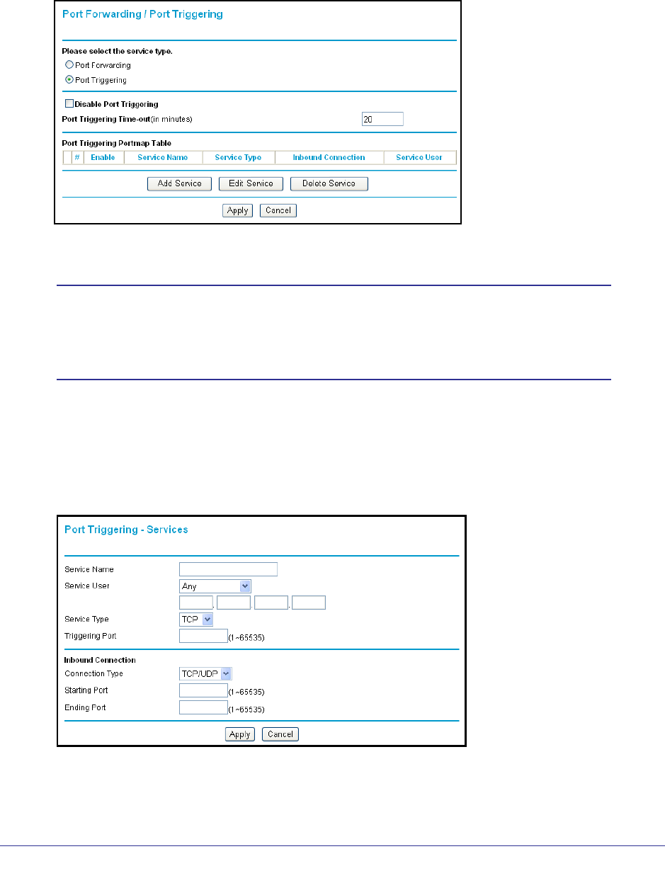
Chapter 4. Content Filtering | 51
NETGEAR N300 Wireless Router with External Antennas WNR1500 User Manual
To set up port triggering:
1. Select Advanced > Port Forwarding/Port Triggering and then select the Port
Triggering radio button. The port triggering information displays.
2. Clear the Disable Port Triggering check box.
Note: If the Disable Port Triggering check box is selected after you
configure port triggering, port triggering is disabled. However, any
port triggering configuration information you added to the router is
retained even though it is not used.
3. In the Port Triggering Timeout field, enter a value up to 9999 minutes. This value controls
the inactivity timer for the designated inbound ports. The inbound ports close when the
inactivity time expires. This is required because the router cannot be sure when the
application has terminated.
4. Click Add Service.
5. The Port Triggering–Services screen displays.
6. In the Service Name field, enter a descriptive service name.
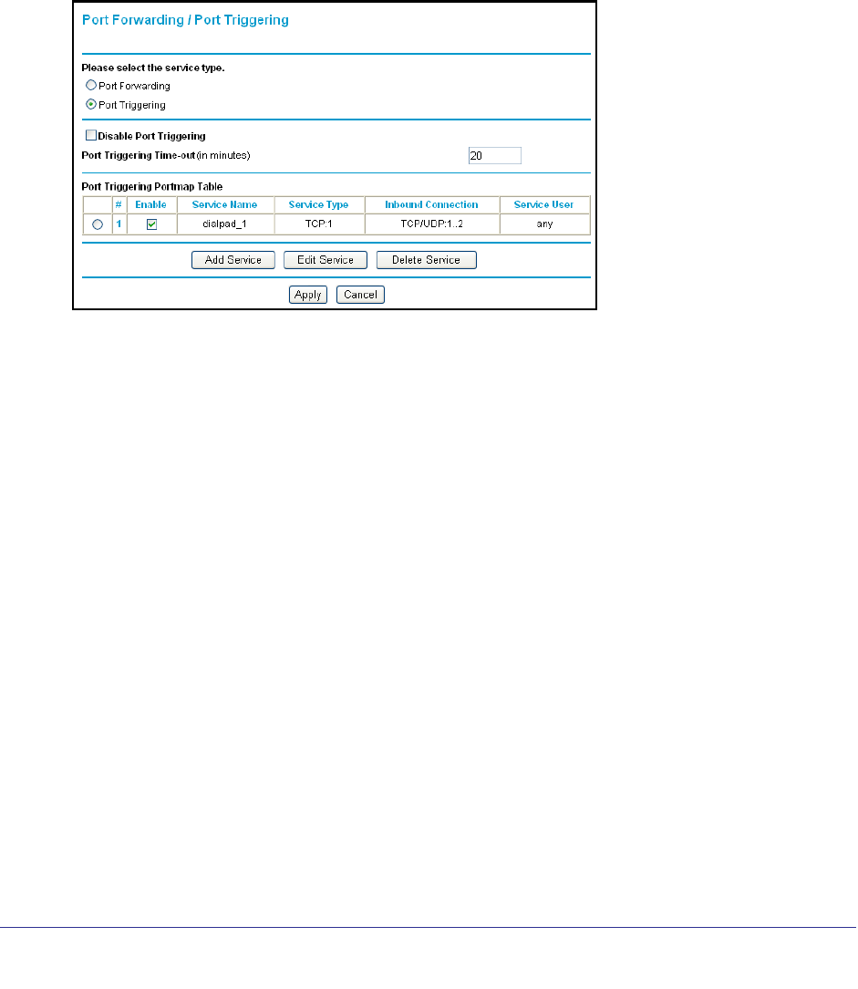
52 | Chapter 4. Content Filtering
NETGEAR N300 Wireless Router with External Antennas WNR1500 User Manual
7. In the Service User field, select Any (the default) to allow this service to be used by any
computer on the Internet. Otherwise, select Single address, and enter the IP address of
one computer to restrict the service to a particular computer.
8. Select the service type, either TCP or UDP.
9. In the Triggering Port field, enter the number of the outbound traffic port that will cause the
inbound ports to be opened.
10. Enter the inbound connection port information in the Connection Type, Starting Port, and
Ending Port fields.
11. Click Apply. The service appears in the Port Triggering Portmap table.

Chapter 5. Network Maintenance | 53
5
5. Network Maintenance
Administering your network
This chapter describes the router settings for administering and maintaining the router and home
network.
This chapter contains the following sections:
• Upgrade the Router Firmware
• Manage the Configuration File
• View Router Status
• View Attached Devices
• Remote Management Access
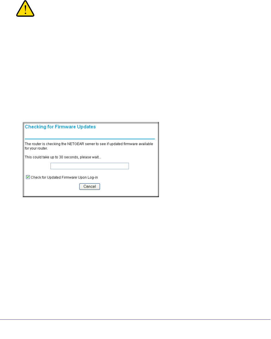
54 | Chapter 5. Network Maintenance
NETGEAR N300 Wireless Router with External Antennas WNR1500 User Manual
Upgrade the Router Firmware
The router firmware (routing software) is stored in flash memory. By default, when you log in
to your router, it checks the NETGEAR website for new firmware and alerts you if there is a
newer version.
WARNING!
When uploading firmware to the router, do not interrupt the Web
browser by closing the window, clicking a link, or loading a new
page. If the browser is interrupted, it could corrupt the firmware.
Turn Off Automatic Firmware Checking
You can turn the automatic firmware checking off and check for firmware updates manually if
you prefer. See Manually Check for Firmware Upgrades on page 55. To turn off the automatic
firmware check at log in:
1. Select Maintenance > Router Upgrade.
2. Clear the Check for Updated Firmware Upon Log-in check box at the bottom of this
screen:.
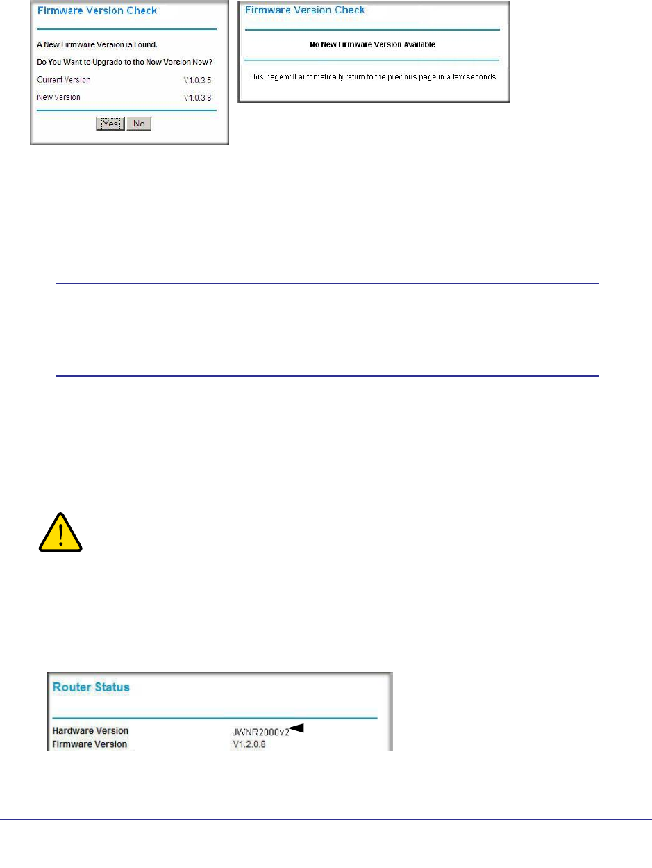
Chapter 5. Network Maintenance | 55
NETGEAR N300 Wireless Router with External Antennas WNR1500 User Manual
Automatic Firmware Checking On
When automatic firmware checking is on, the router performs the check and notifies you if an
upgrade is available or not as shown here.
1. Click Yes to allow the router to download and install the new firmware. The upgrade
process could take a few minutes. When the upload is complete, your router restarts.
2. Go to the WNR1500 support page at http://www.netgear.com/support. and read the new
firmware release notes to determine whether you need to reconfigure the modem router
after upgrading.
Note: If you get a “Firmware needs to be reloaded” message, it means a
problem has been detected with the router’s firmware. Follow the
prompts to correct the problem or see the next section for a
description of the steps.
Manually Check for Firmware Upgrades
You can use the Router Upgrade screen to manually check the NETGEAR website for newer
versions of firmware for your product.
WARNING!
When uploading firmware to the router, do not interrupt the Web
browser by closing the window, clicking a link, or loading a new
page. If the browser is interrupted, it could corrupt the firmware.
1. Select Maintenance > Router Status and make a note of the router firmware version
number
Firmware Version
.
2. Go to the WNR1500 support page on the NETGEAR website at
http://www.netgear.com/support.
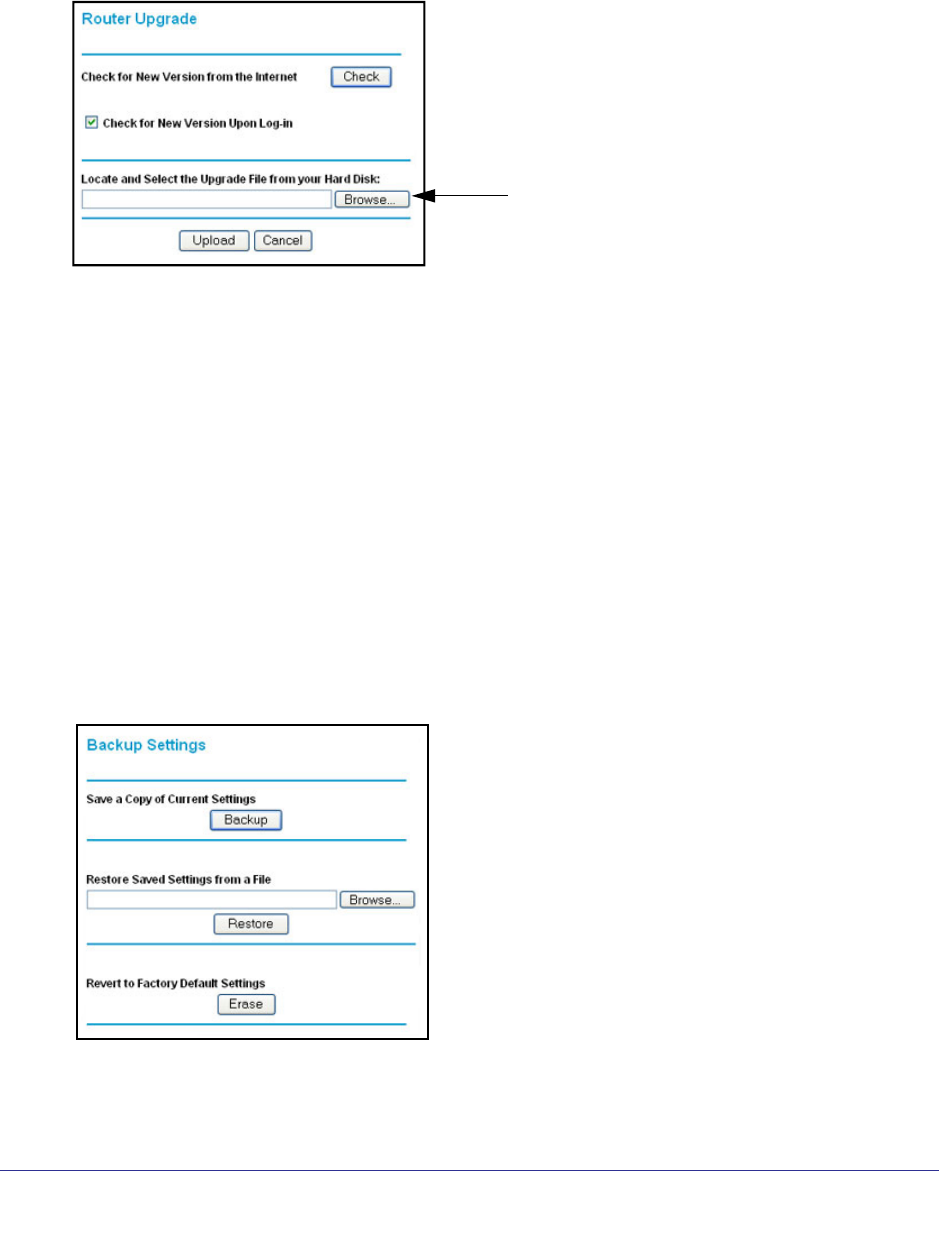
56 | Chapter 5. Network Maintenance
NETGEAR N300 Wireless Router with External Antennas WNR1500 User Manual
3. If the firmware version on the NETGEAR website is newer than the firmware on your router,
download the file to your computer.
4. To upload the newer firmware, select Maintenance > Router Upgrade to display the
following screen:
Click Browse
5. Click Browse, and locate the firmware you downloaded (the file ends in .img).
6. Click Upload to send the firmware to the router.
When the upload completes, your router restarts. The upgrade process typically takes
about one minute. Read the new firmware release notes to determine whether or not you
need to reconfigure the router after upgrading.
Manage the Configuration File
The router configuration settings are stored in a configuration file (*.cfg). This file can be
backed up to your computer, restored, or reverted to factory default settings.
Back Up
1. Select Maintenance > Backup Settings to display the following screen:
2. Click Backup to save a copy of the current settings.
3. Choose a location to store the .cfg file that is on a computer on your network.

Chapter 5. Network Maintenance | 57
NETGEAR N300 Wireless Router with External Antennas WNR1500 User Manual
Restore
1. Enter the full path to the file on your network, or click the Browse button to find the file.
2. When you have located the .cfg file, click the Restore button to upload the file to the router.
Upon completion, the router reboots.
WARNING!
Do not interrupt the reboot process.
Erase
Under some circumstances (for example, if you move the router to a different network or if
you have forgotten the password), you might want to erase the configuration and restore the
factory default settings.
Click the Erase button to reset the router to its factory default settings. Alternately, press the
Wireless On/Off and WPS buttons on the side panel of the router simultaneously for 6
seconds.
Erase sets the user name to admin, the password to password, the LAN IP address to
192.168.1.1, and enables the router’s DHCP.
To restore the factory default configuration settings when you do not know the login password
or IP address, use the restore factory settings button on the bottom of the router (see Restore
the Default Configuration and Password on page 94).
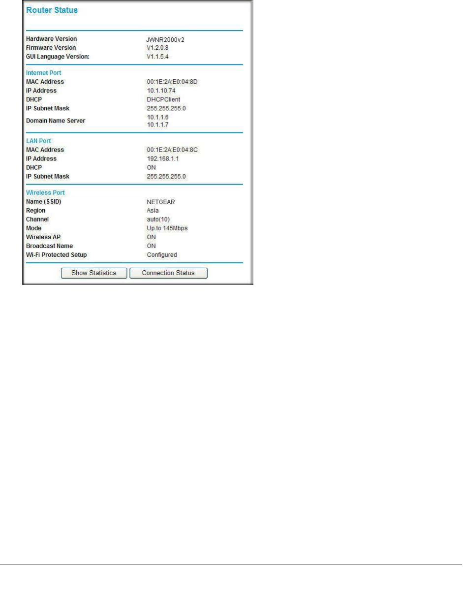
58 | Chapter 5. Network Maintenance
NETGEAR N300 Wireless Router with External Antennas WNR1500 User Manual
View Router Status
Select Maintenance > Router Status to display the following screen. The Router Status
screen provides the status and usage information described in the following figure.
Hardware Version. The firmware version.
Firmware Version. The version of the current software installed in the router. This changes if
you update your router.
GUI Language Version. The version of the selected GUI language for the router manager
screens.
Internet Port.
MAC Address. The Ethernet MAC address of the Internet port.
IP Address. The Internet port IP address. If no address is shown, the router cannot
connect to the Internet.
DHCP. If set to None, the router is configured to use a fixed IP address on the WAN. If set
to DHCP Client, the router is configured to obtain an IP address dynamically from the ISP.
IP Subnet Mask. The Internet port IP subnet mask.
Domain Name Server. The router DNS server IP addresses. These addresses are
usually obtained dynamically from the ISP.
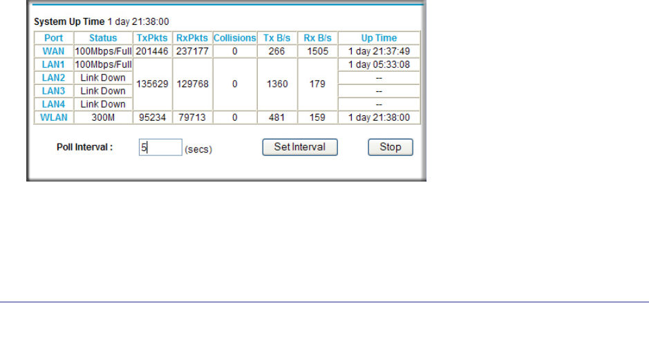
Chapter 5. Network Maintenance | 59
NETGEAR N300 Wireless Router with External Antennas WNR1500 User Manual
LAN Port (Local Ports).
MAC Address. The router LAN port Ethernet MAC address.
IP Address. The router LAN port IP address. The default is 192.168.0.1.
DHCP. If Off, the router does not assign IP addresses to PCs on the LAN. If On, the router
does assign IP addresses to PCs on the LAN.
IP Subnet Mask. The IP subnet mask used by the router LAN. The default is
255.255.255.0.
Wireless Port.
See Wireless Settings on page 31 for more information on these settings.
Name (SSID). The Wi-Fi network name (service set ID) for the wireless network.
Region. The country where the unit is set up for use.
Channel. The current channel, which determines the operating frequency.
Mode. Indicates the wireless communication mode:
• Up to 54 Mbps.
• Up to 145 Mbps.
• Up to 300 Mbps (in this mode, there are two channels: a primary channel [P] and a
secondary channel [S]).
Wireless AP. Indicates if the access point feature is enabled. If disabled, the Wireless
LED on the front panel is off.
Broadcast Name. Indicates if the router is configured to broadcast its SSID.
Wi-Fi Protected Setup. Indicates whether the router’s PIN is enabled and whether the
router is configured for Push ‘N’ Connect (Wi-Fi Protected Setup).
Show Statistics Button. Click the Show Statistics button on the Router Status screen to
display a screen similar to this:
• System Up Time. The time elapsed since the router was last restarted.
• Port. The statistics for the WAN (Internet) and LAN (Ethernet) ports. For each port, the
screen displays the following:
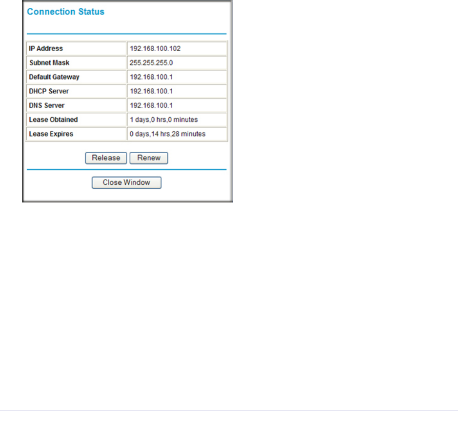
60 | Chapter 5. Network Maintenance
NETGEAR N300 Wireless Router with External Antennas WNR1500 User Manual
Status. The link status of the port.
TxPkts. The number of packets transmitted on this port since reset or manual clear.
RxPkts. The number of packets received on this port since reset or manual clear.
Collisions. The number of collisions on this port since reset or manual clear.
Tx B/s. The current transmission (outbound) bandwidth used on the WAN and LAN ports
Rx B/s. The current reception (inbound) bandwidth used on the WAN and LAN ports.
Up Time. The time elapsed since this port acquired the link.
• Poll Interval. The intervals at which the statistics are updated in this screen.
To change the polling frequency, enter a time in seconds in the Poll Interval field, and click
Set Interval. To stop the polling entirely, click Stop.
Connection Status Button. In the Router Status screen, click the Connection Status button
to display a screen similar to this:
IP Address. The IP address that is assigned to the router.
Subnet Mask. The subnet mask that is assigned to the router.
Default Gateway. The IP address for the default gateway that the router communicates with.
DHCP Server. The IP address for the Dynamic Host Configuration Protocol server that
provides the TCP/IP configuration for all the computers that are connected to the router.
DNS Server. The IP address of the Domain Name Service server that provides translation of
network names to IP addresses.
Lease Obtained. The date and time that the lease was obtained.
Lease Expires. The date and time that the lease expires.
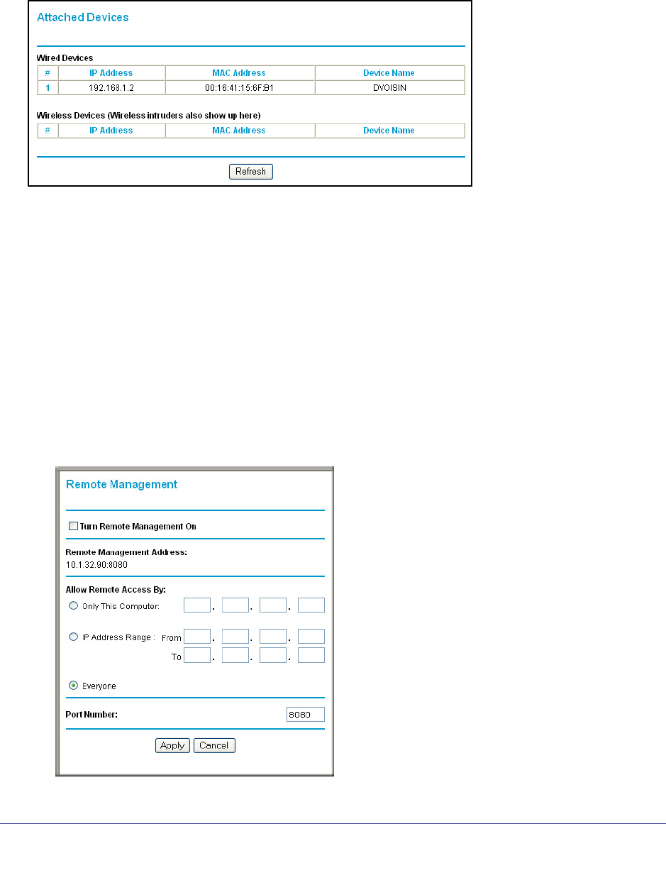
Chapter 5. Network Maintenance | 61
NETGEAR N300 Wireless Router with External Antennas WNR1500 User Manual
View Attached Devices
The Attached Devices screen presents a table of all IP devices that the router has discovered
on the local network. Select Maintenance > Attached Devices to view the following table:
For each device, the table shows the IP address, device name if available, and the Ethernet
MAC address. Note that if the router is rebooted, the table data is lost until the router
rediscovers the devices. To force the router to look for attached devices, click the Refresh
button.
Remote Management Access
Using the Remote Management feature, you can allow a user on the Internet to configure,
upgrade, and check the status of your WNR1500 router.
To set up your router for remote management:
1. Select Advanced > Remote Management. The Remote Management screen displays.

62 | Chapter 5. Network Maintenance
NETGEAR N300 Wireless Router with External Antennas WNR1500 User Manual
2. Make sure that you have changed the router’s default password to a very secure password.
The ideal password should contain no dictionary words from any language, and should be
a mixture of letters (both uppercase and lowercase), numbers, and symbols. Your
password can be up to 30 characters.
3. Select the Turn Remote Management On check box.
4. Under Allow Remote Access By, specify what external IP addresses will be allowed to
access the router’s remote management.
For enhanced security, restrict access to as few external IP addresses as practical.
• To allow access from any IP address on the Internet, select Everyone.
• To allow access from a range of IP addresses on the Internet, select IP Address
Range.
Enter a beginning and ending IP address to define the allowed range.
• To allow access from a single IP address on the Internet, select Only This Computer.
Enter the IP address that will be allowed access.
5. Specify the port number for accessing the management interface.
Normal Web browser access uses the standard HTTP service port 80. For greater
security, enter a custom port number for the remote management Web interface. Choose
a number between 1024 and 65535, but do not use the number of any common service
port. The default is 8080, which is a common alternate for HTTP.
6. Click Apply to have your changes take effect.
When accessing your router from the Internet, enter your router’s WAN IP address into your
browser’s address or location field, followed by a colon (:) and the custom port number. For
example, if your external address is 134.177.0.123 and you use port number 8080, then
enter http://134.177.0.123:8080 in your browser.

Chapter 6. Advanced Settings | 63
6
6. Advanced Settings
Configuring for unique situations
This chapter describes the advanced features of your router. The information is for users with a
solid understanding of networking concepts who want to set the router up for unique situations
such as when remote access from the Internet by IP or domain name is needed.
It contains the following sections:
• WAN Setup
• Dynamic DNS
• LAN Setup
• Advanced Wireless Settings
• Set Up Static Routes
• Quality of Service
• Universal Plug and Play
• Wireless Repeating (Also Called WDS)
For information about port triggering and port forwarding, see Chapter 4, Content Filtering.
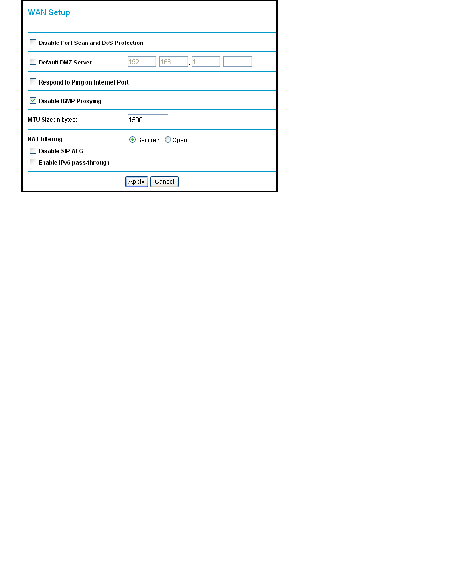
64 | Chapter 6. Advanced Settings
NETGEAR N300 Wireless Router with External Antennas WNR1500 User Manual
WAN Setup
The WAN Setup screen lets you disable port scan and DoS protection, configure a DMZ
(demilitarized zone) server, enable the router to respond to a ping on the WAN (Internet) port,
enable IGMP proxying, and change the Maximum Transmit Unit (MTU) size.
Select Advanced > WAN Setup to display the following screen:
Disable Port Scan and DOS Protection. The firewall protects your LAN against port scans
and denial of service (DOS) attacks. This protection should be disabled only in special
circumstances.
Default DMZ Server. The default demilitarized zone (DMZ) server feature is helpful when
you use online games and video conferencing applications that are incompatible with NAT.
The router is programmed to recognize some of these applications and to work correctly with
them, but there are other applications that might not function well. In some cases, one local
computer can run the application correctly if that computer’s IP address is entered as the
default DMZ server.
Respond to Ping on Internet. If you want the router to respond to a ping from the Internet,
select this check box. This should be used only as a diagnostic tool, because it allows your
router to be discovered. Do not select this check box unless you have a specific reason to do
so.
Disable IGMP Proxying. IGPM (Internet Group Management Protocol) proxying is disabled
by default. When IGPM Proxying is enabled, your router acts as an IGMP-based host,
forwarding IGMP messages and responding to IGMP queries.
MTU Size (in bytes). The normal Maximum Transmit Unit (MTU) value for most Ethernet
networks is 1500 bytes, or 1492 bytes for PPPoE connections. For some ISPs you might
need to reduce the MTU. But this is rarely required, and should not be done unless you are
sure it is necessary for your ISP connection.

Chapter 6. Advanced Settings | 65
NETGEAR N300 Wireless Router with External Antennas WNR1500 User Manual
NAT Filtering. Network Address Translation (NAT) determines how the router processes
inbound traffic. Secured NAT provides a secured firewall to protect the computers on the LAN
from attacks from the Internet, but might prevent some Internet games, point-to-point
applications, or multimedia applications from functioning. Open NAT provides a much less
secured firewall, but allows almost all Internet applications to function.
• Disabling the SIP ALG. The Session Initiation Protocol (SIP) Application Level Gateway
(ALG) is enabled by default to optimize VoIP phone calls that use the SIP. The Disable
SIP ALG check box allows you to disable the SIP ALG. Disabling the SIP ALG might be
useful when running certain applications.
• Enable IPv6 pass-through. Select this check box if your Internet service provider (ISP)
specifies that your Internet connection uses IPv6 pass-through.
Set Up a Default DMZ Server
Note: For security reasons, you should avoid using the default DMZ server
feature. When a computer is designated as the default DMZ server,
it loses much of the protection of the firewall and is exposed to many
exploits from the Internet. If compromised, the computer can be
used to attack your network.
Incoming traffic from the Internet is usually discarded by the router unless the traffic is a
response to one of your local computers or a service that you have configured in the Ports
screen. Instead of discarding this traffic, you can have it forwarded to one computer on your
network. This computer is called the default DMZ server.
To assign a computer or server to be a default DMZ server:
1. In the WAN screen, select the Default DMZ Server check box
2. In the Default DMZ Server fields, enter the IP address for that computer or server.
3. Click Apply.
Dynamic DNS
If your Internet Service Provider (ISP) gave you a permanently assigned IP address, you can
register a domain name and have that name linked with your IP address by public Domain
Name Servers (DNS). However, if your Internet account uses a dynamically assigned IP
address, you do not know in advance what your IP address will be, and the address can
change frequently. In this case, you can use a commercial Dynamic DNS service, which
allows you to register your domain to their IP address, and forwards traffic directed at your
domain to your frequently changing IP address.
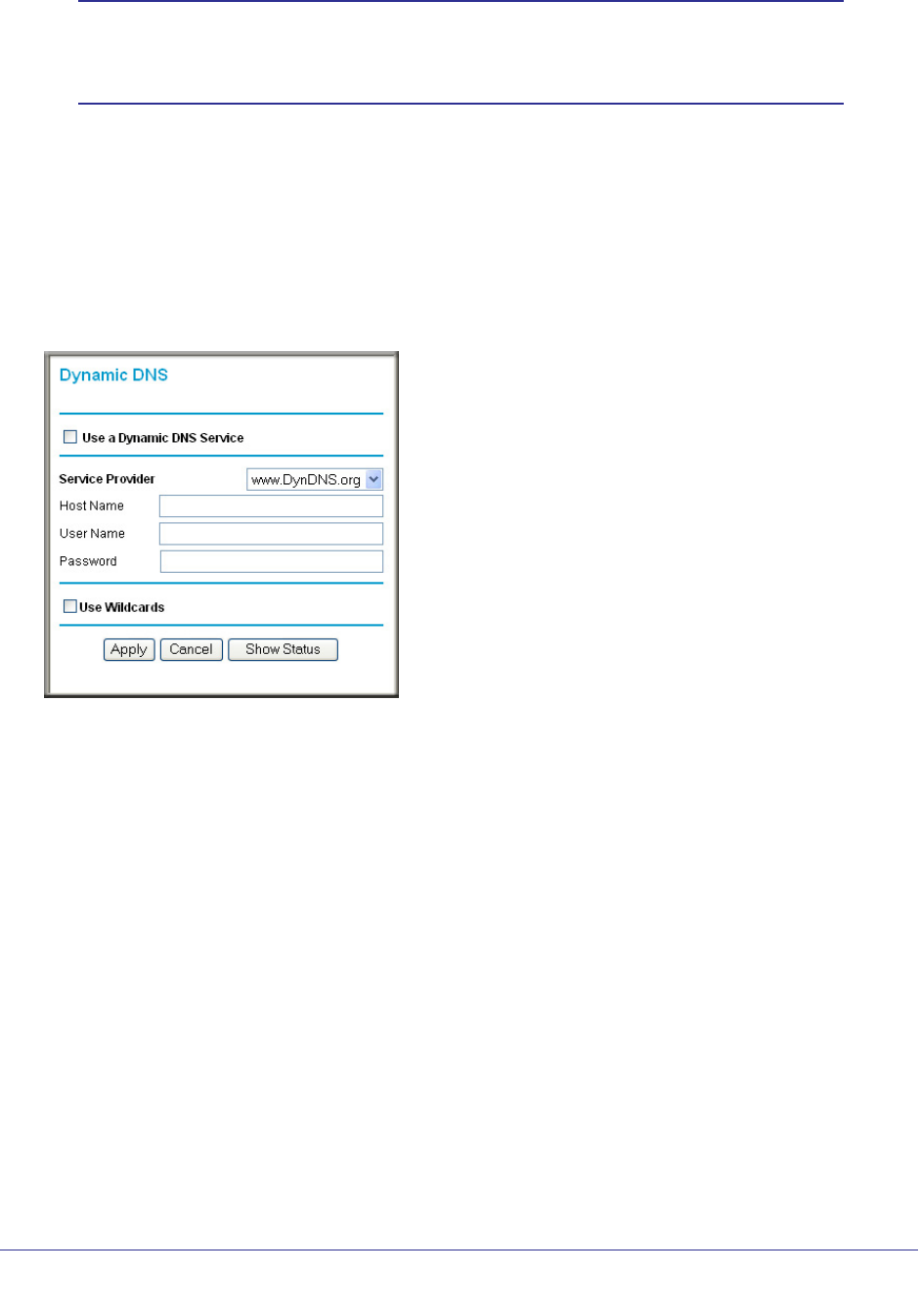
66 | Chapter 6. Advanced Settings
NETGEAR N300 Wireless Router with External Antennas WNR1500 User Manual
Note: If your ISP assigns a private WAN IP address (such as 192.168.x.x
or 10.x.x.x), the Dynamic DNS service does not work because
private addresses are not routed on the Internet.
Your router contains a client that can connect to the Dynamic DNS service provided by
DynDNS.org. You must first visit their website at www.dyndns.org and obtain an account and
host name, which you specify in the router. Then, whenever your ISP-assigned IP address
changes, your router automatically contacts the Dynamic DNS service provider, logs in to
your account, and registers your new IP address. If your host name is hostname, for
example, you can reach your router at hostname.dyndns.org.
Select Advanced > Dynamic DNS. The Dynamic DNS screen displays.
To configure for a Dynamic DNS service:
1. Register for an account with one of the Dynamic DNS service providers whose names
appear in the Service Provider list. For example, for DynDNS.org, select
www.dynDNS.org.
2. Select the Use a Dynamic DNS Service check box.
3. Select the name of your Dynamic DNS service provider.
4. Enter the host name (or domain name) that your Dynamic DNS service provider gave you.
5. Enter the user name for your Dynamic DNS account. This is the name that you use to log in
to your account, not your host name.
6. Enter the password (or key) for your Dynamic DNS account.
7. If your Dynamic DNS provider allows the use of wildcards in resolving your URL, you can
select the Use Wildcards check box to activate this feature.
For example, the wildcard feature causes *.yourhost.dyndns.org to be aliased to the same IP
address as yourhost.dyndns.org.
8. Click Apply to save your configuration.
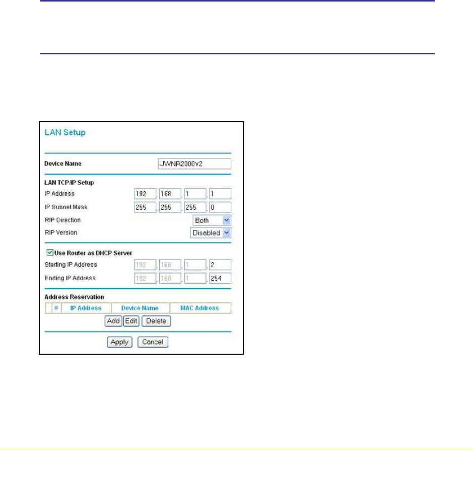
Chapter 6. Advanced Settings | 67
NETGEAR N300 Wireless Router with External Antennas WNR1500 User Manual
LAN Setup
The LAN Setup screen allows configuration of LAN IP services such as DHCP and Routing
Information Protocol (RIP). The router is shipped preconfigured to use private IP addresses
on the LAN side and to act as a DHCP server. The router’s default LAN IP configuration is as
follows:
• LAN IP address. 192.168.0.1
• Subnet mask. 255.255.255.0
These addresses are part of the private address range designated by the Internet
Engineering Task Force (IETF http://www.ietf.org/) for use in private networks, and should be
suitable in most applications. If your network has a requirement to use a different IP
addressing scheme, you can make those changes in the LAN IP Setup screen.
Note: If you change the LAN IP address of the router while connected
through the browser, you are disconnected. To reconnect, open a
new connection to the new IP address and log in.
To configure LAN settings:
1. Select Advanced > LAN Setup. The LAN Setup screen displays.
2. Enter the configuration and click Apply to save your changes.

68 | Chapter 6. Advanced Settings
NETGEAR N300 Wireless Router with External Antennas WNR1500 User Manual
LAN Setup Screen Fields
Device Name. The device name is a user-friendly name for the router. This name is shown in
the Network on Windows Vista and the Network Explorer on all Windows systems. The
Device Name field cannot be blank. The default name is WNR1500.
LAN TCP/IP Setup
IP Address. The LAN IP address of the router.
IP Subnet Mask. The LAN subnet mask of the router. Combined with the IP address, the
IP subnet mask allows a device to know which other addresses are local to it, and which
have to be reached through a gateway or router.
RIP Direction. RIP allows a router to exchange routing information with other routers.
The RIP Direction selection controls how the router sends and receives RIP packets. The
default setting is Both.
• When set to Both or Out Only, the router broadcasts its routing table periodically.
• When set to Both or In Only, the router incorporates the RIP information that it
receives.
• When set to None, the router does not send any RIP packets and ignores any RIP
packets received.
RIP Version. This controls the format and the broadcasting method of the RIP packets
that the router sends. It recognizes both formats when receiving. By default, this is set for
RIP-1.
• RIP-1. This version is universally supported. It is probably adequate for most
networks, unless you have an unusual network setup.
• RIP-2. This version carries more information. Both RIP-2B and RIP-2M send the
routing data in RIP-2 format.
• RIP-2B. This version uses subnet broadcasting.
• RIP-2M. This version uses multicasting.
Use Router as a DHCP Server. By default, the router functions as a DHCP server, allowing
it to assign IP, DNS server, and default gateway addresses to all computers connected to the
router’s LAN. See Use the Router as a DHCP Server on page 68.
Address Reservation. When you specify a reserved IP address for a computer on the LAN,
that computer always receives the same IP address each time it accesses the router’s DHCP
server. Reserved IP addresses should be assigned to computers or servers that require
permanent IP settings. See Reserved IP Addresses Setup on page 69.
Use the Router as a DHCP Server
By default, the router functions as a DHCP server, allowing it to assign IP, DNS server, and
default gateway addresses to all computers connected to the router’s LAN. The assigned
default gateway address is the LAN address of the router. The router assigns IP addresses to

Chapter 6. Advanced Settings | 69
NETGEAR N300 Wireless Router with External Antennas WNR1500 User Manual
the attached computers from a pool of addresses specified in this screen. Each pool address
is tested before it is assigned to avoid duplicate addresses on the LAN.
Note: For most applications, the default DHCP and TCP/IP settings of the
router are satisfactory.
To specify a pool of IP addresses to be assigned, set the starting IP address and ending IP
address. These addresses should be part of the same IP address subnet as the router’s LAN
IP address. Using the default addressing scheme, you should define a range between
192.168.1.2 and 192.168.1.254, although you might wish to save part of the range for
devices with fixed addresses.
The router delivers the following parameters to any LAN device that requests DHCP:
• An IP address from the range you have defined
• Subnet mask
• Gateway IP address (the router’s LAN IP address)
• Primary DNS server (if you entered a primary DNS address in the Basic Settings screen;
otherwise, the router’s LAN IP address)
• Secondary DNS server (if you entered a secondary DNS address in the Basic Settings
screen)
To use another device on your network as the DHCP server, or to manually specify the
network settings of all of your computers, clear the Use Router as DHCP Server check box.
Otherwise, leave it selected. If this service is not selected and no other DHCP server is
available on your network, you need to set your computers’ IP addresses manually or they
will not be able to access the router.
Reserved IP Addresses Setup
When you specify a reserved IP address for a computer on the LAN, that computer always
receives the same IP address each time it accesses the router’s DHCP server. Reserved IP
addresses should be assigned to servers that require permanent IP settings.
To reserve an IP address:
1. Select Advanced > LAN Setup and click the Add button.
2. In the IP Address field, type the IP address to assign to the computer or server. Choose an
IP
address from the router’s LAN subnet, such as 192.168.0.x.
3. Type the MAC address of the computer or server.
Tip: If the computer is already present on your network, copy its MAC
address from the Attached Devices screen and paste it here.
4. Click Apply to enter the reserved address into the table.
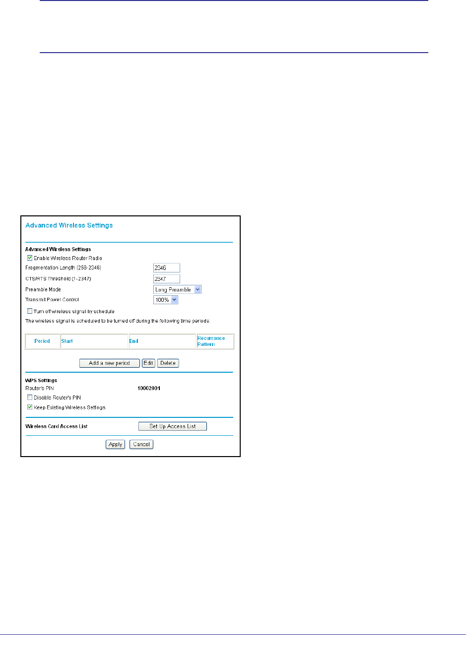
70 | Chapter 6. Advanced Settings
NETGEAR N300 Wireless Router with External Antennas WNR1500 User Manual
Note: The reserved address is not assigned until the next time the
computer contacts the router’s DHCP server. Reboot the computer
or access its IP configuration to force a DHCP release and renew.
To edit or delete a reserved address entry:
1. Click the button next to the reserved address that you want to edit or delete.
2. Click Edit or Delete.
Advanced Wireless Settings
Select Advanced > Advanced Wireless Settings. The Advanced Wireless Settings screen
displays:
Advanced Wireless Settings
• Enable Wireless Router Radio. If you disable the wireless router radio, wireless devices
cannot connect to the WNR1500 router. If you will not be using your wireless network for
a period of time, you can clear this check box and disable all wireless connectivity.
• Fragmentation Length, CTS/RTS Threshold, Preamble Mode and Transmit Power
Control. The Fragmentation Threshold, CTS/RTS Threshold, Preamble Mode, and
Transmit Power Control options are reserved for wireless testing and advanced
configuration only. Do not change these settings.
• WPS Settings. For information about these settings, see the section, Advanced Wireless
Settings on page 70.

Chapter 6. Advanced Settings | 71
NETGEAR N300 Wireless Router with External Antennas WNR1500 User Manual
• Wireless Card Access List. For information about this list, see Restrict Wireless Access
by MAC Address on page 71.
WPS Settings
These options are available if the settings in the Wireless Settings screen are compatible with
WPS.
• Router’s PIN. The PIN is displayed so that you can use it to configure the router through
WPS (Wi-Fi Protected Setup). It is also displayed on the router’s label.
• Disable Router’s PIN. If the router’s PIN is disabled, you cannot configure the router’s
wireless settings with WPS. However, if your settings are already configured, you can still
add WPS-enabled wireless clients. The router might disable the PIN if it detects
suspicious attempts to break into your wireless settings; this can happen if the check box
is selected. You can enable the PIN by clearing the check box and clicking Apply.
• Keep Existing Wireless Settings. This check box is automatically selected after WPS is
enabled to prevent unwanted settings changes, and is also selected if you have already
specified wireless security settings or your SSID without using WPS. When this check
box is not selected, adding a new wireless client using the push button or the Add WPS
Client screen (see Wi-Fi Protected Setup (WPS) Method on page 30) changes the
router’s SSID and security passphrase. You might need to clear it if you are using certain
registrars, such as for a Windows Vista PC, to configure the router through WPS.
Wireless Card Access List
You can use this feature to restrict access by MAC address as described in the following
section.
Restrict Wireless Access by MAC Address
MAC address filtering adds an obstacle against unwanted access to your network by the
general public. However, because your trusted MAC addresses appear in your wireless
transmissions, an intruder can read them and impersonate them. Do not rely on MAC
address filtering alone to secure your network.
When a wireless card access list is configured and enabled, the router checks the MAC
address of any wireless device attempting a connection and allows only connections to
computers identified on the trusted computers list.
The Wireless Card Access List displays a list of wireless computers that you allow to connect
to the router based on their MAC addresses. These wireless computers must also have the
correct SSID and wireless security settings to access the wireless router.
The MAC address is a network device’s unique 12-character physical address, containing the
hexadecimal characters 0–9, a–f, or A–F only, and separated by colons (for example,
00:09:AB:CD:EF:01). It can usually be found on the bottom of the wireless card or network
interface device. If you do not have access to the physical label, you can display the MAC
address using the network configuration utilities of the computer. In WindowsXP, for example,
typing the ipconfig/all command in an MSDOS command prompt window displays the
MAC address as Physical Address. You might also find the MAC addresses in the router’s
Attached Devices screen.
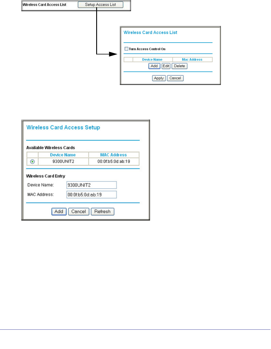
72 | Chapter 6. Advanced Settings
NETGEAR N300 Wireless Router with External Antennas WNR1500 User Manual
To restrict access based on MAC addresses:
1. Select Advanced > Wireless Settings.
2. In the Advanced Wireless Settings screen, click Setup Access List to display the Wireless
Card Access List.
3. Click Add to add a wireless device to the wireless access control list. The Wireless Card
Access Setup screen opens and displays a list of currently active wireless cards and their
Ethernet MAC addresses.
4. If the computer you want appears in the Available Wireless Cards list, you can select the
radio button of that computer to capture its MAC address; otherwise, you can manually enter
a name and the MAC address of the authorized computer. You can usually find the MAC
address on the bottom of the wireless device.
Tip: You can copy and paste the MAC addresses from the router’s Attached
Devices screen into the MAC Address field of this screen. To do this,
configure each wireless computer to obtain a wireless link to the router.
The computer should then appear in the Attached Devices screen.
5. Click Add to add this wireless device to the Wireless Card Access List. The screen changes
back to the list screen.

Chapter 6. Advanced Settings | 73
NETGEAR N300 Wireless Router with External Antennas WNR1500 User Manual
6. Repeat step 3 through step 5 for each additional device you want to add to the list.
7. Select the Turn Access Control On check box
When configuring the router from a wireless computer whose MAC address is not in the
Trusted PC list, if you select Turn Access Control On, you lose your wireless connection
when you click Apply. You must then access the router from a wired computer or from a
wireless computer that is on the access control list to make any further changes.
8. Click Apply to save your Wireless Card Access List settings.
Now, only devices on this list can wirelessly connect to the WNR1500 router.
Set Up Static Routes
Static routes provide additional routing information to your router. Under usual
circumstances, the router has adequate routing information after it has been configured for
Internet access, and you do not need to configure additional static routes. You must configure
static routes only for unusual cases such as multiple routers or multiple IP subnets located on
your network.
As an example of when a static route is needed, consider the following case:
• Your primary Internet access is through a cable modem to an ISP.
• You have an ISDN router on your home network for connecting to the company where
you are employed. This router’s address on your LAN is 192.168.1.100.
• Your company’s network address is 134.177.0.0.
When you first configured your router, two implicit static routes were created. A default route
was created with your ISP as the gateway, and a second static route was created to your
local network for all 192.168.1.x addresses. With this configuration, if you attempt to access a
device on the 134.177.0.0 network, your router forwards your request to the ISP. The ISP
forwards your request to the company where you are employed, and the request is likely to
be denied by the company’s firewall.
In this case you must define a static route, telling your router that 134.177.0.0 should be
accessed through the ISDN router at 192.168.1.100.
In this example:
• The Destination IP Address and IP Subnet Mask fields specify that this static route
applies to all 134.177.x.x addresses.
• The Gateway IP Address field specifies that all traffic for these addresses should be
forwarded to the ISDN router at 192.168.1.100.
• A Metric value of 1 will work since the ISDN router is on the LAN.
• Private is selected only as a precautionary security measure in case RIP is activated.
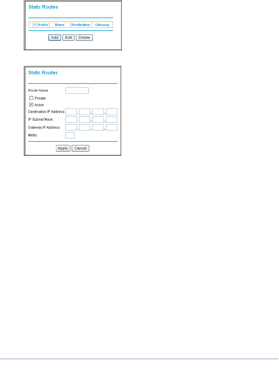
74 | Chapter 6. Advanced Settings
NETGEAR N300 Wireless Router with External Antennas WNR1500 User Manual
To add or edit a static route:
1. Select Advanced > Static Routes. The Static Routes screen displays.
2. Click Add to expand the Static Routes screen.
3. In the Route Name field, enter a name for this static route. (This is for identification purposes
only.)
4. Select the Private check box if you want to limit access to the LAN only. If Private is
selected, the static route is not reported in RIP.
5. Select the Active check box to make this route effective.
6. In the Destination IP Address field, enter the IP address of the final destination.
7. In the IP Subnet Mask field, enter the IP subnet mask for this destination.
If the destination is a single host, enter 255.255.255.255.
8. In the Gateway IP Address field, enter the gateway IP address, which must be a router on
the same LAN segment as the WNR1500 router.
9. In the Metric field, enter a number between 1 and 15 as the metric value.
This represents the number of routers between your network and the destination. Usually,
a setting of 2 or 3 works, but if this is a direct connection, set it to 1.
10. Click Apply to have the static route entered into the table.
Quality of Service
Quality of Service (QoS) is an advanced feature that can be used to prioritize some types of
traffic ahead of others. The WNR1500 router can provide QoS prioritization over the wireless
link.
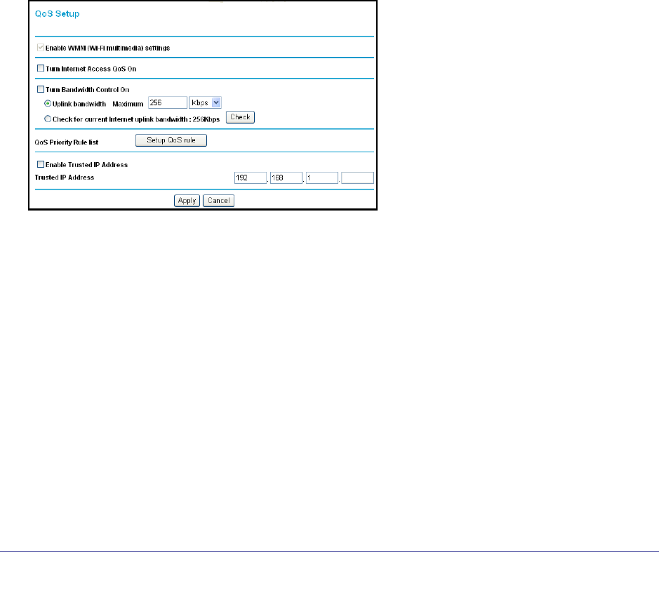
Chapter 6. Advanced Settings | 75
NETGEAR N300 Wireless Router with External Antennas WNR1500 User Manual
WMM QoS for Wireless Multimedia Applications
The WNR1500 router supports Wi-Fi Multimedia Quality of Service (WMM QoS) to prioritize
wireless voice and video traffic over the wireless link. WMM QoS provides prioritization of
wireless data packets from different applications based on four access categories: voice,
video, best effort, and background. For an application to receive the benefits of WMM QoS,
both it and the client running that application must be WMM enabled. Legacy applications
that do not support WMM, and applications that do not require QoS, are assigned to the best
effort category, which receives a lower priority than voice and video.
QoS for Internet Access
To specify prioritization of traffic, you must create a policy for the type of traffic and add the
policy to the QoS Policy table in the QoS Setup screen.
To create a QoS policy:
From the main menu of the browser interface, under Advanced, select QoS Setup. The QoS
Setup screen displays:
WMM QoS is enabled by default. You can disable it by clearing the Enable WMM check box
and clicking Apply.
To create a QoS policy for applications or online games:
1. Select Advanced > QoS Setup.
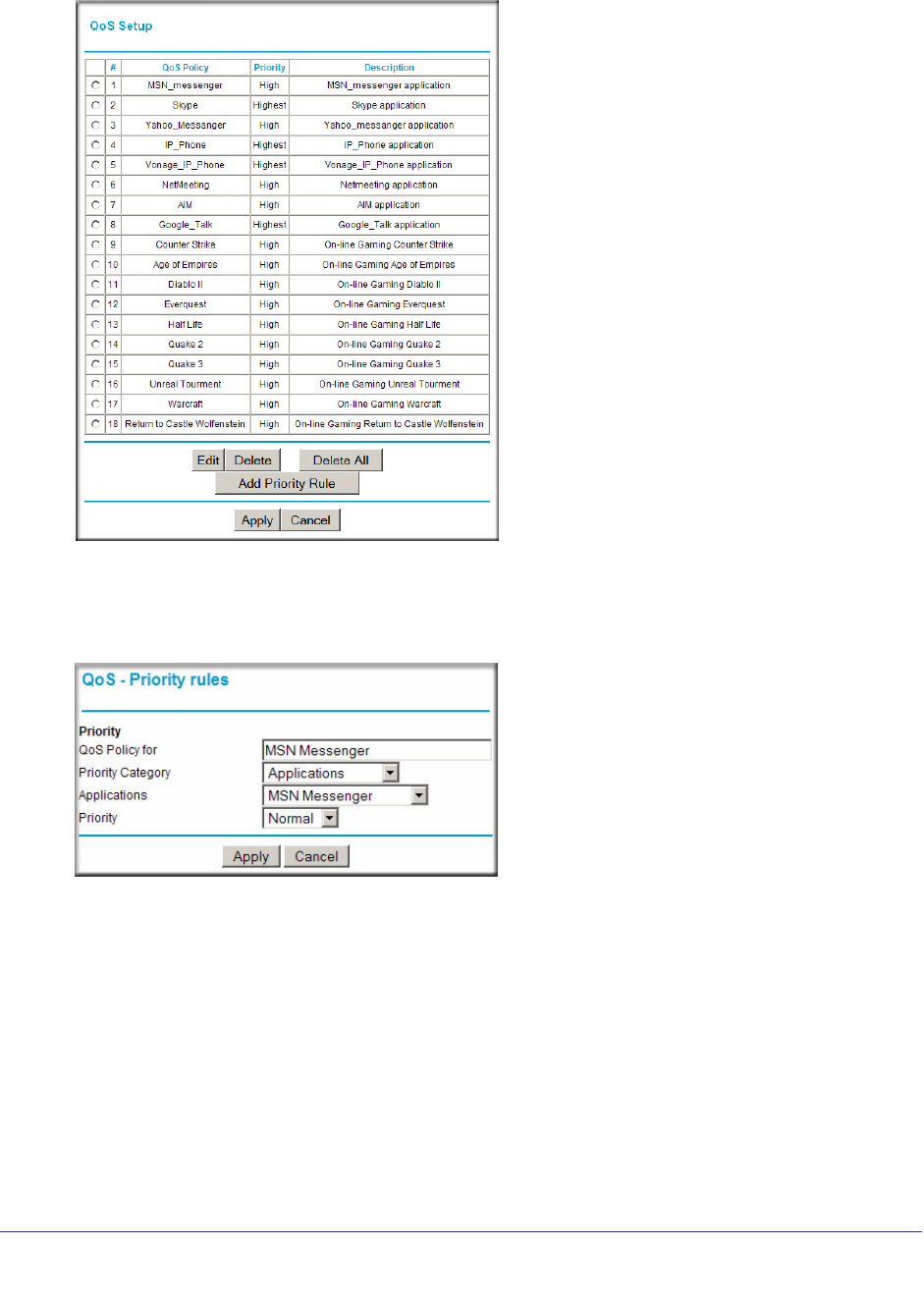
76 | Chapter 6. Advanced Settings
NETGEAR N300 Wireless Router with External Antennas WNR1500 User Manual
2. On the QoS screen, click Setup QoS rule. The QoS - Priority Rules screen displays.
For convenience, the QoS Policy table lists many common applications and online games
that can benefit from QoS handling.
3. Click Add Priority Rule. The QoS - Priority Rules screen displays.
4. In the Priority Category list, select either Applications or Online Gaming. In either case, a
list of predefined applications or games displays in the Applications drop-down list.
5. From the Applications list, you can select an existing item, or you can scroll to the bottom of
the list and select Add a New Application or Add a New Game.
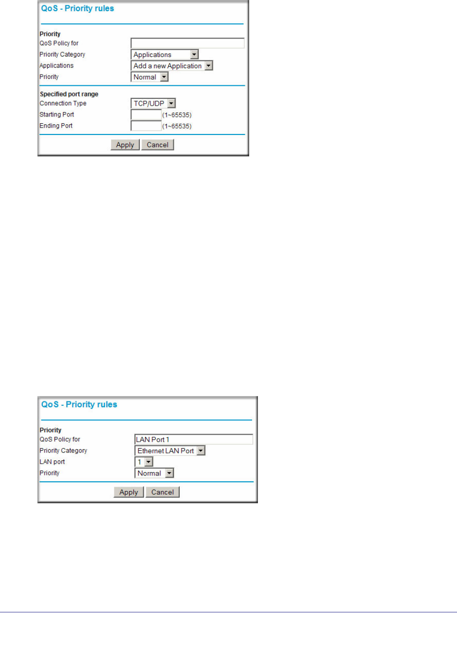
Chapter 6. Advanced Settings | 77
NETGEAR N300 Wireless Router with External Antennas WNR1500 User Manual
If you chose to add a new entry, the screen expands as shown:
a. In the QoS Policy for field, enter a descriptive name for the new application or game.
b. Select the packet type, either TCP, UDP, or both (TCP/UDP), and specify the port
number or range of port numbers used by the application or game.
6. From the Priority drop-down list, select the priority that this traffic should receive relative to
other applications and traffic when accessing the Internet. The options are Low, Normal,
High, and Highest.
7. Click Apply to save this rule to the QoS Policy list and return to the QoS Setup screen.
8. In the QoS Setup screen, select the Turn Internet Access QoS On check box.
9. Click Apply.
To create a QoS policy for a router LAN ports:
1. Select Advanced > QoS Setup.
2. On the QoS Setup screen, click Add Priority Rule.
3. From the Priority Category list, select Ethernet LAN Port. The QoS - Priority Rules screen
changes:
4. From the LAN port list, select the LAN port that will have a QoS policy.
5. From the Priority drop-down list, select the priority that this port’s traffic should receive
relative to other applications and traffic when accessing the Internet. The options are Low,
Normal, High, and Highest.
6. Click Apply to save this rule to the QoS Policy list and return to the QoS Setup screen.
7. In the QoS Setup screen, select the Turn Internet Access QoS On check box.
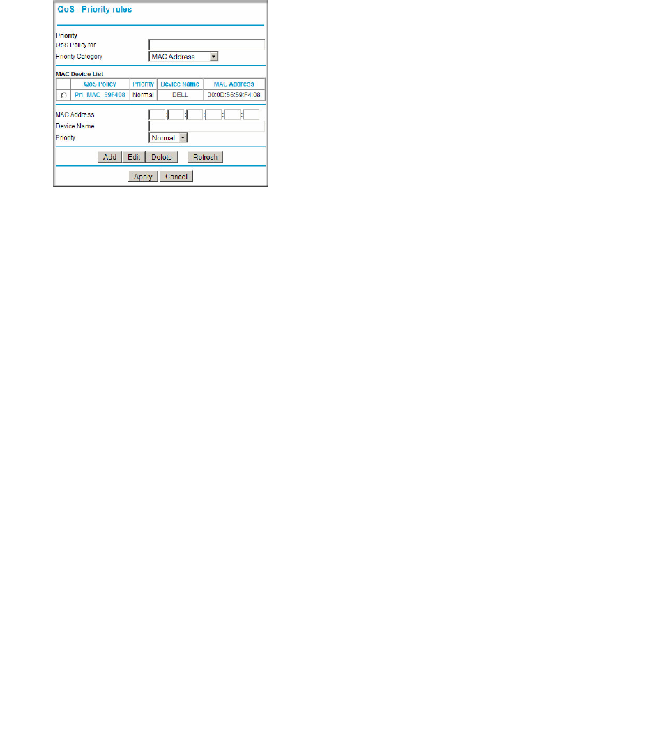
78 | Chapter 6. Advanced Settings
NETGEAR N300 Wireless Router with External Antennas WNR1500 User Manual
8. Click Apply.
QoS for a MAC Address
To create a QoS policy for traffic from a specific MAC address:
1. Select Advanced > QoS Setup. The QoS Setup screen displays.
2. On the QoS Setup screen, click Add Priority Rule.
3. From the Priority Category list, select MAC Address. The QoS - Priority Rules screen
changes:
4. If the device to be prioritized appears in the MAC Device List, select it. The information from
the MAC Device List is used to populate the policy name, MAC Address, and Device Name
fields. If the device does not appear in the MAC Device List, click Refresh. If it still does not
appear, you must complete these fields manually.
5. From the Priority drop-down list, select the priority that this device’s traffic should receive
relative to other applications and traffic when accessing the Internet. The options are Low,
Normal, High, and Highest.
6. Click Apply to save this rule to the QoS Policy list and return to the QoS Setup screen.
7. In the QoS Setup screen, select the Turn Internet Access QoS On check box.
8. Click Apply.
To edit or delete an existing QoS policy:
1. Select Advanced > QoS Setup. The QoS Setup screen displays.
2. On the QoS Setup screen, select the radio button next to the QoS policy to be edited or
deleted, and do one of the following:
• Click Delete to remove the QoS policy.
• Click Edit to edit the QoS policy. Follow the instructions in the preceding sections to
change the policy settings.
3. Click Apply in the QoS Setup screen to save your changes.
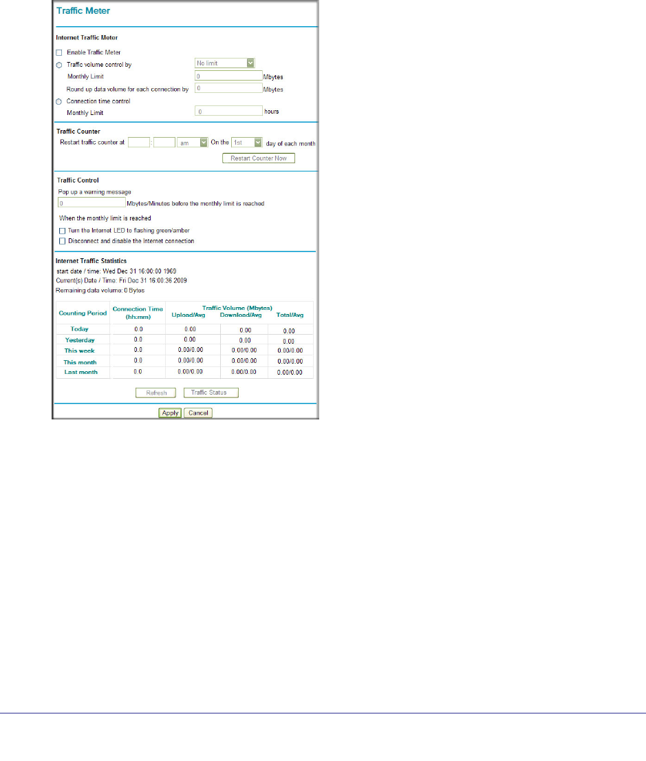
Chapter 6. Advanced Settings | 79
NETGEAR N300 Wireless Router with External Antennas WNR1500 User Manual
Traffic Meter
Traffic Metering allows you to monitor the volume of Internet traffic passing through your
router’s Internet port. With the Traffic Meter utility, you can set limits for traffic volume, set a
monthly limit, and get a live update of traffic usage.
To monitor traffic on your router, do the following:
1. Select Advanced > Traffic Meter.
2. Select the Enable Traffic Meter check box.
3. Click Apply.
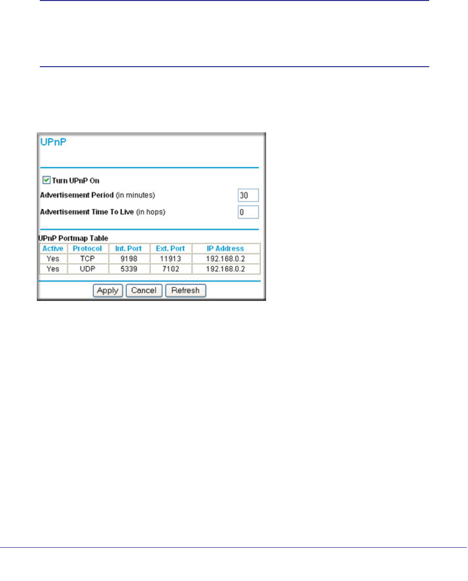
80 | Chapter 6. Advanced Settings
NETGEAR N300 Wireless Router with External Antennas WNR1500 User Manual
Universal Plug and Play
Universal Plug and Play (UPnP) helps devices, such as Internet appliances and computers,
to access the network and connect to other devices as needed. UPnP devices can
automatically discover the services from other registered UPnP devices on the network.
Note: If you use applications such as multiplayer gaming, peer-to-peer
connections, real-time communications such as instant messaging,
or remote assistance (a feature in Windows XP), you should enable
UPnP.
To turn on Universal Plug and Play:
1. Select Advanced > UPnP. The UPnP screen displays.
2. The available settings and information displayed in this screen are:
• Turn UPnP On. UPnP can be enabled or disabled for automatic device configuration.
The default setting for UPnP is disabled. If this check box is not selected, the router
does not allow any device to automatically control the resources, such as port
forwarding (mapping) of the router.
• Advertisement Period. The advertisement period is how often the router broadcasts
its UPnP information. This value can range from 1 to 1440 minutes. The default period
is 30 minutes. Shorter durations ensure that control points have current device status
at the expense of additional network traffic. Longer durations might compromise the
freshness of the device status but can significantly reduce network traffic.
• Advertisement Time To Live. The time to live for the advertisement is measured in
hops (steps) for each UPnP packet sent. The time to live hop count is the number of
steps a broadcast packet is allowed to propagate for each UPnP advertisement
before it disappears. The number of hops can range from 1 to 255. The default value
for the advertisement time to live is 4 hops, which should be fine for most home
Chapter 6. Advanced Settings | 81
NETGEAR N300 Wireless Router with External Antennas WNR1500 User Manual
networks. If you notice that some devices are not being updated or reached correctly,
then it might be necessary to increase this value.
• UPnP Portmap Table. The UPnP Portmap Table displays the IP address of each
UPnP device that is currently accessing the router and which ports (Internal and
External) that device has opened. The UPnP Portmap Table also displays what type
of port is open and whether that port is still active for each IP address.
3. Click Apply to save your settings.
Wireless Repeating (Also Called WDS)
The router can be used with a wireless access point (AP) to build large bridged wireless
networks. Wireless repeating is a type of Wireless Distribution System (WDS).
WARNING!
If you use the wireless repeating function, your options for
wireless security are limited to None or WEP. For more
information about wireless security, see Wireless Settings on
page 27.
The following figure shows a wireless repeating scenario:
Repeater AP
Base Station AP
Figure 1. Wireless repeating example
To set up a wireless network using WDS, he following conditions must be met for both APs:
• Both APs must use the same SSID, wireless channel, and encryption mode.
• Both APs must be on the same LAN IP subnet. That is, all the access point LAN IP
addresses are in the same network.
• All LAN devices (wired and wireless computers) must be configured to operate in the
same LAN network address range as the APs.
• If you make changes in the Wireless Settings screen, click Apply so that they take effect.
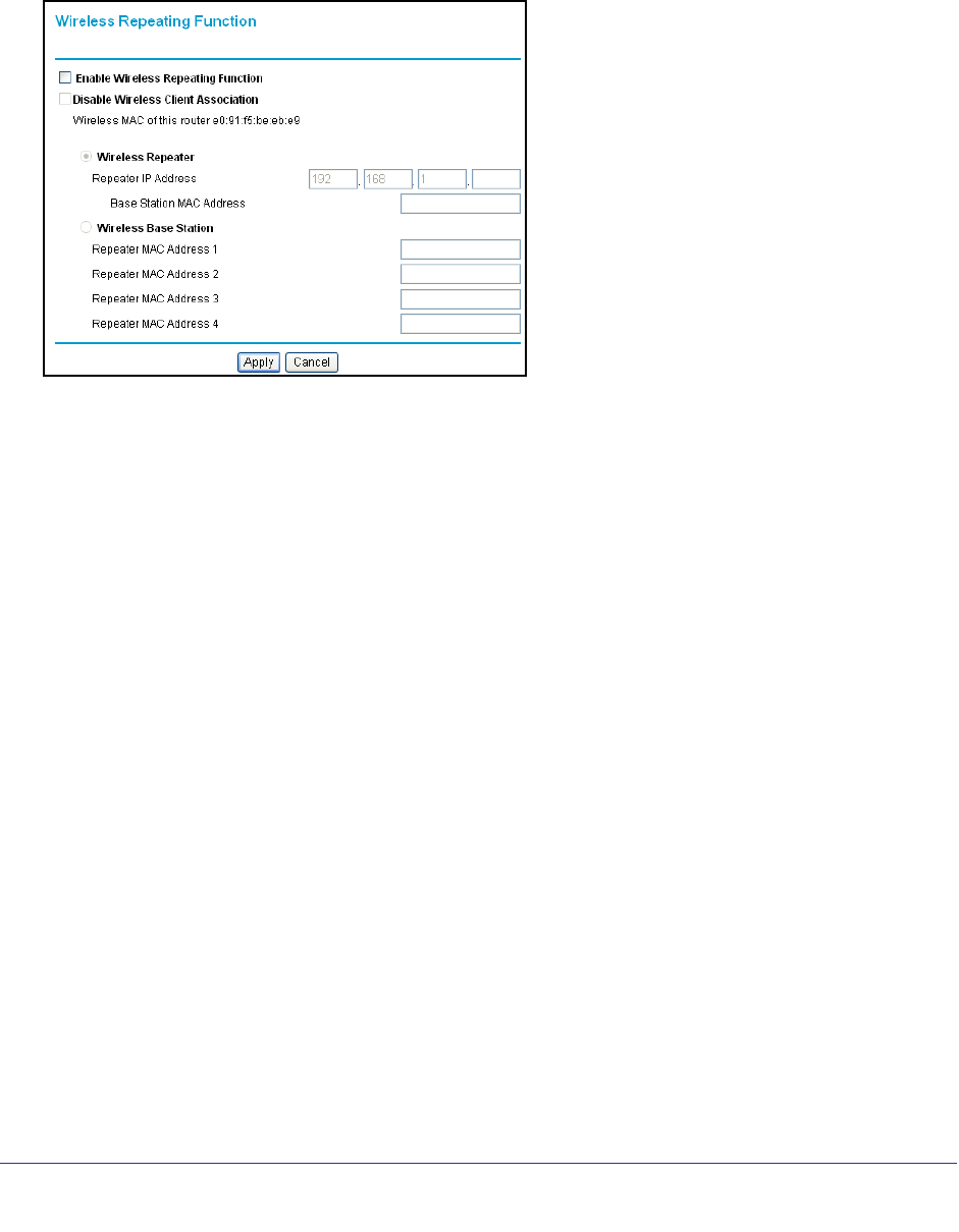
82 | Chapter 6. Advanced Settings
NETGEAR N300 Wireless Router with External Antennas WNR1500 User Manual
Wireless Repeating Function
You can view or change wireless repeater settings for the router. From the main menu of the
browser interface, under Advanced, click Wireless Repeating Function to display the
Wireless Repeating Function screen.
The router supports two modes of the wireless repeating function, and allows you to control
wireless client association:
• Wireless Repeater. The router sends all traffic from its local wireless or wired computers
to a remote access point. To configure this mode, you must know the MAC address of the
remote parent access point.
• Wireless Base Station. The router acts as the parent access point, bridging traffic to and
from the child repeater access point, as well as handling wireless and wired local
computers. To configure this mode, you must know the MAC addresses of the child
repeater access point.
• Disable Wireless Client Association. Usually this check box is cleared so that the
router is an access point for wireless computers.
If this check box is selected, the router communicates wirelessly only with other APs
whose MAC addresses are listed in this screen. The router still communicates with
wire-connected LAN devices.
Set Up the Base Station
The wireless repeating function works only in hub and spoke mode. The units cannot be
daisy chained. You must know the wireless settings for both units. You must know the MAC
address of the remote unit. First, set up the base station, and then set up the repeater.
To set up the base station:
1. Set up both units with exactly the same wireless settings (SSID, mode, channel, and
security). Note that the wireless security option must be set to None or WEP.
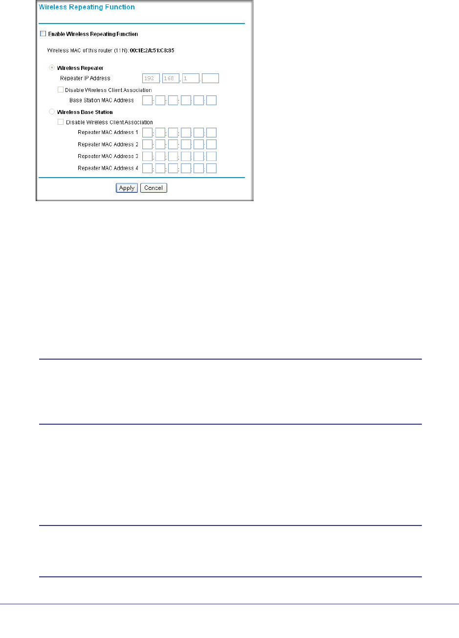
Chapter 6. Advanced Settings | 83
NETGEAR N300 Wireless Router with External Antennas WNR1500 User Manual
2. Log into the router base unit, under the Advanced heading, select Wireless Repeating
Function to display the Wireless Repeating Function screen.
3. Select the Enable Wireless Repeating Function check box and the Wireless Base
Station radio button.
4. Enter the MAC address for the repeater units.
5. Click Apply to save your changes.
Set Up a Repeater Unit
Use a wired Ethernet connection to set up the repeater unit to avoid conflicts with the
wireless connection to the base station.
Note: If you are using the WNR1500 base station with a non-NETGEAR
router as the repeater, you might need to change additional
configuration settings. In particular, you should disable the DHCP
server function on the wireless repeater access point.
To configure a WNR1500 router as a repeater unit:
1. If you are using the same model of router for both the base station and repeaters, you
must change the LAN IP address for each repeater to a different IP address in the same
subnet (see LAN Setup on page 67).
Note: Failing to change the LAN IP address will cause an IP address
conflict in the network because the factory default LAN IP is the
same for both units.

84 | Chapter 6. Advanced Settings
NETGEAR N300 Wireless Router with External Antennas WNR1500 User Manual
2. Log in to the router that will be the repeater. Check the Wireless Settings screen, and verify
that the wireless settings match the base station exactly. If the settings are different, be sure
to configure the wireless settings to match the base station settings (see Wireless Settings
on page 31).
3. In the Wireless Repeating Function screen, select the Enable Wireless Repeating
Function check box and the Wireless Repeater radio button.
4. Fill in the IP Address field. This IP address must be in the same subnet as the base station,
but different from the LAN IP of the base station.
5. Fill in the Base Station MAC Address field.
6. Click Apply to save your changes.
7. Verify connectivity across the LANs.
A computer on any wireless or wired LAN segment of the router should be able to
connect to the Internet or share files and printers with any other wireless or wired
computer or server connected to the other access point.

Chapter 7. Troubleshooting | 85
7
7. Troubleshooting
This chapter provides information about troubleshooting your N300 Wireless Router with
External Antennas WNR1500. After each problem description, instructions are provided to
help you diagnose and solve the problem. As a first step, please review the Quick Tips.
Tip: NETGEAR provides helpful articles, documentation, and the latest
software updates at http://www.netgear.com/support.
This chapter includes the following sections:
• Quick Tips
• Troubleshooting Basic Functions
• Login Problems
• Check the Internet Service Connection
• Troubleshoot Your Network Using the Ping Utility
• Problems with Date and Time
• Problems with Wireless Adapter Connections
• Restore the Default Configuration and Password

86 | Chapter 7. Troubleshooting
NETGEAR N300 Wireless Router with External Antennas WNR1500 User Manual
Quick Tips
This section describes tips for troubleshooting some common problems:
Be sure to restart your network in this sequence.
1. Turn off and unplug the modem.
2. Turn off the router and computers.
3. Plug in the modem and turn it on. Wait 2 minutes.
4. Turn on the router and wait 1 minute.
5. Turn on the computers.
Make sure that the Ethernet cables are securely plugged in.
• The Internet status LED on the router is on if the Ethernet cable connecting the router and
the modem is plugged in securely and the modem and router are turned on.
• For each powered-on computer connected to the router by an Ethernet cable, the
corresponding numbered router LAN port LED is on.
Make sure that the wireless settings in the computer and router match exactly.
• For a wirelessly connected computer, the wireless network name (SSID) and WEP or
WPA security settings of the router and wireless computer must match exactly.
• If you have enabled the router to restrict wireless access by MAC address, you must add
the wireless computer’s MAC address to the router’s wireless card access list.
Make sure that the network settings of the computer are correct.
• LAN connected computers must be configured to obtain an IP address automatically
using DHCP.
• Some cable modem services require you to use the MAC address of the computer
registered on the account. If so, in the Router MAC Address section of the Basic Settings
menu, select Use this Computer’s MAC Address. Click Apply to save your settings.
Restart the network in the correct sequence.
Troubleshooting Basic Functions
After you turn on power to the router, the following sequence of events should occur:
1. When power is first applied, verify that the power/check icon is on.
2. Verify that the Power/check LED turns green and blinks slowly, indicating that the system is
initializing.
3. After approximately 20 seconds, verify that:
a. The Power/Check LED changes to solid green.
b. The LAN port lights are lit for any local ports that are connected.

Chapter 7. Troubleshooting | 87
NETGEAR N300 Wireless Router with External Antennas WNR1500 User Manual
If a port’s LED is lit, a link has been established to the connected device. If a LAN port
is connected to a 100 Mbps device, verify that the port’s LED is green. If the port is 10
Mbps, the LED is amber.
c. The Internet port is connected and its LED is lit.
4. If you have enabled WPS security, verify that the WPS LED stops blinking and changes to
green (otherwise the WPS LED should be off).
If the correct behavior does not occur, see the appropriate following section.
The Power/Check LED is off.
If the Power and other lights are off when your router is turned on:
• Make sure that the power cord is properly connected to your router and that the power
adapter is properly connected to a functioning power outlet.
• Check that you are using the power adapter supplied by NETGEAR for this product.
If the error persists, you have a hardware problem and should contact Technical Support.
The Power/Check LED blinks green slowly and continuously (Case 1).
The router firmware is corrupted or system initialization has failed.
To restore your firmware:
1. Make sure your PC is connected to your router and the router is powered on.
2. Download the firmware from the NETGEAR support page.
3. Follow the instructions to restore your firmware.
4. After firmware recovery is complete, follow the prompts to restore your configuration
settings.
The Power/Check LED blinks green slowly and continuously (Case 2).
If the Power/Check LED continues to blink for over 1 minute after powering on power to the
router:
1. Turn the power off and back on to see if the router recovers.
2. Clear the router’s configuration to factory defaults. This will set the router’s IP address to
192.168.1.1. This procedure is explained in Restore the Default Configuration and Password
on page 94.
If the error persists, you might have a hardware problem and should contact Technical
Support.
The Internet or LAN port lights are not on.
If a LAN or Internet LED does not light when the Ethernet connection is made, check the
following:
1. Make sure that the Ethernet cable connections are secure at the router and at the
computer.
2. Make sure that power is turned on to the connected computer.

88 | Chapter 7. Troubleshooting
NETGEAR N300 Wireless Router with External Antennas WNR1500 User Manual
3. Be sure you are using Ethernet cables like the cable that was supplied with the router. See
the NETGEAR Wireless Router Setup Manual for instructions.
Login Problems
If you are unable to log in to the router, check the following:
• If you are using an Ethernet-connected computer, check the Ethernet connection
between the computer and the router as described in the NETGEAR Wireless Router
Setup Manual.
• Make sure you are using the correct login information. The factory default login name is
admin and the password is password. Make sure that the Caps Lock is off when
entering this information.
• Make sure your computer’s IP address is on the same subnet as the router. If your are
using the recommended addressing scheme, your computer’s address should be in the
range of 192.168.1.2 to 192.168.1.254. Refer to your computer’s documentation.
Note: If your computer cannot reach a DHCP server, some operating
systems will assign an IP address in the range 169.254.x.x. If your
IP address is in this range, verify that you have a good connection
from the computer to the router, then restart (reboot) your computer.
• If your router’s IP address has been changed and you don’t know the current IP address,
reset the router’s configuration to the factory defaults. This procedure will reset the
router’s IP address to 192.168.1.1 (see Factory Default Settings in Appendix A).
• Make sure your browser has Java, JavaScript, or ActiveX enabled. If you are using
Internet Explorer, click Refresh to be sure the Java applet is loaded. Try closing the
browser and reopening it again.
• If you are attempting to set up your NETGEAR router as an additional router behind an
existing router in your network, consider replacing the existing router instead. NETGEAR
does not support such a configuration.
• If you are attempting to set up your NETGEAR router as a replacement for an ADSL
gateway in your network, the router cannot perform many gateway services, for example,
converting ADSL or Cable data into Ethernet networking information. NETGEAR does not
support such a configuration.

Chapter 7. Troubleshooting | 89
NETGEAR N300 Wireless Router with External Antennas WNR1500 User Manual
Check the Internet Service Connection
If you can access your router, but your router is unable to access the Internet, review the
topics in this section:
• Obtaining an Internet IP Address
• Troubleshooting PPPoE
• Troubleshooting Internet Browsing
Obtaining an Internet IP Address
If your router is unable to access the Internet, and your Internet LED is amber, check the
router to see if it is able to get an Internet IP address from your service provider. Unless you
have a static IP address, your router automatically requests an IP address from your service
provider.
To check your router’s Internet IP address:
1. Log in to the router.
2. Select Maintenance > Router Status to check that an IP address is shown for the Internet
Port. If 0.0.0.0 is shown, your router has not obtained an IP address from your service
provider.
If your router is unable to obtain an IP address from the your service provider, the problem
might be one of the following:
• You might need to force your cable or DSL modem to recognize your new router by
restarting your network, in the sequence described in the NETGEAR Wireless Router
Setup Manual.
• Your service provider might require a login. Ask your service provider whether they
require a PPP over Ethernet (PPPoE) login (see Troubleshooting PPPoE on page 90).
• You might have incorrectly set the service name, user name or password. Review your
router’s Basic Settings screen.
• Your service provider might check for your computer's host name. Assign the computer
Host Name of your ISP account to the router on the Basic Settings screen.
• Your service provider might only allow one Ethernet MAC address to connect to the
Internet, and check for your computer’s MAC address. If this is the case:
-Inform your service provider that you have bought a new network device, and ask
them to use the router’s MAC address, or
-Configure your router to spoof your computer’s MAC address. On the Basic Settings
screen in the Router MAC Address section, select “Use this Computer’s MAC
Address” and click Apply. Then restart your network in the correct sequence (see the
NETGEAR Wireless Router Setup Manual for instructions).

90 | Chapter 7. Troubleshooting
NETGEAR N300 Wireless Router with External Antennas WNR1500 User Manual
Troubleshooting PPPoE
If you are using PPPoE, try troubleshooting your Internet connection.
To troubleshoot a PPPoE connection:
1. Log in to the router.
2. Select Maintenance > Router Status.
3. Click Connection Status. If all of the steps indicate “OK,” then your PPPoE connection is up
and working.
If any of the steps indicate “Failed,” you can attempt to reconnect by clicking Connect.
The router will continue to attempt to connect indefinitely.
If you cannot connect after several minutes, you might be using an incorrect service
name, user name, or password. There also might be a provisioning problem with your
ISP.
Note: Unless you connect manually, the router will not authenticate using
PPPoE until data is transmitted to the network.
Troubleshooting Internet Browsing
If your router can obtain an IP address but your computer is unable to load any web pages
from the Internet, check the following:
• Your computer might not recognize any DNS server addresses. A DNS server is a
host on the Internet that translates Internet names (such as www addresses) to numeric
IP
addresses. Typically, your ISP will provide the addresses of one or two DNS servers
for your use. If you entered a DNS address during the router’s configuration, restart your
computer. Alternatively, you can configure your computer manually with a DNS address,
as explained in the documentation for your computer.
• Your computer might not have the router configured as its default gateway. Reboot
the computer and verify that the router address (192.168.1.1) is listed by your computer
as the default gateway address.
• You might be running login software that is no longer needed. If your ISP provided a
program to log you in to the Internet (such as WinPoET), you no longer need to run that
software after installing your router. You might need to go to Internet Explorer and select
Tools > Internet Options, click the Connections tab, and select Never dial a
connection.
If the router does not save changes you have made in the browser interface, check the
following:
• When entering configuration settings, be sure to click Apply before moving to another
screen or tab, or your changes could be lost.

Chapter 7. Troubleshooting | 91
NETGEAR N300 Wireless Router with External Antennas WNR1500 User Manual
• Click Refresh or Reload in the Web browser. The changes might have occurred, but the
Web browser might be caching the old configuration.
Troubleshoot Your Network Using the Ping Utility
Most network devices and routers contain a ping utility that sends an echo request packet to
the designated device. The device then responds with an echo reply. Troubleshooting a
network is made very easy by using the ping utility in your computer or workstation. This
section includes:
• Test the LAN Path to Your Router
• Test the Path from Your Computer to a Remote Device
Test the LAN Path to Your Router
You can ping the router from your computer to verify that the LAN path to your router is set up
correctly.
To ping the router from a running Windows PC:
1. From the Windows toolbar, click Start, and then select Run.
2. In the field provided, type ping followed by the IP address of the router, as in this example:
ping www.routerlogin.net
3. Click OK.
You should see a message like this one:
Pinging <IP address > with 32 bytes of data
If the path is working, you see this message:
Reply from < IP address >: bytes=32 time=NN ms TTL=xxx
If the path is not working, you see this message:
Request timed out
If the path is not functioning correctly, you could have one of the following problems:
• Wrong physical connections
- For a wired connection, make sure that the numbered LAN port LED is on for the
port to which you are connected. If the LED is off, follow the instructions in
Troubleshooting Basic Functions on page 86.
- Check that the appropriate LEDs are on for your network devices. If your router
and computer are connected to a separate Ethernet switch, make sure that the
link lights are on for the switch ports that are connected to your computer and
router.
• Wrong network configuration

92 | Chapter 7. Troubleshooting
NETGEAR N300 Wireless Router with External Antennas WNR1500 User Manual
- Verify that the Ethernet card driver software and TCP/IP software are both
installed and configured on your computer.
- Verify that the IP address for your router and your computer are correct and that
the addresses are on the same subnet.
Test the Path from Your Computer to a Remote Device
After verifying that the LAN path works correctly, test the path from your computer to a remote
device.
1. From the Windows toolbar, click the Start button, and then select Run.
2. In the Windows Run window, type:
ping -n 10 <IP address>
where <IP address> is the IP address of a remote device such as your ISP’s DNS server.
If the path is functioning correctly, replies like those shown in the previous section are
displayed. If you do not receive replies:
• Check that your computer has the IP address of your router listed as the default gateway.
If the IP configuration of your computer is assigned by DHCP, this information is not be
visible in your computer’s Network Control Panel. Verify that the IP address of the router
is listed as the default gateway.
• Check to see that the network address of your computer (the portion of the IP address
specified by the subnet mask) is different from the network address of the remote device.
• Check that your cable or DSL modem is connected and functioning.
• If your ISP assigned a host name to your computer, enter that host name as the account
name in the Basic Settings screen.
• Your ISP could be rejecting the Ethernet MAC addresses of all but one of your computers.
Many broadband ISPs restrict access by allowing traffic only from the MAC address of
your broadband modem, but some ISPs additionally restrict access to the MAC address
of a single computer connected to that modem. If this is the case, you must configure
your router to “clone” or “spoof” the MAC address from the authorized computer.
Problems with Date and Time
Select Content Filtering > Email to display a screen that shows the current date and time of
day. The WNR1500 router uses the Network Time Protocol (NTP) to obtain the current time
from one of several network time servers on the Internet. Each entry in the log is stamped
with the date and time of day. Problems with the date and time function can include the
following:
• Date shown is January 1, 2000.
Cause: The router has not yet successfully reached a network time server. Check that
your Internet access settings are correct. If you have just completed configuring the
router, wait at least 5 minutes, and check the date and time again.

Chapter 7. Troubleshooting | 93
NETGEAR N300 Wireless Router with External Antennas WNR1500 User Manual
• Time is off by one hour.
Cause: The router does not adjust for daylight savings time. In the E-mail screen, select
the Automatically Adjust for Daylight Savings Time check box.
Problems with Wireless Adapter Connections
If your wireless adapter is unable to connect, check its connection settings.
To check the adapter’s connection settings:
1. Open the adapter setup utility to check connections:
• NETGEAR Smart Wizard utility. If you installed a NETGEAR wireless adapter in
your computer, a Smart Wizard utility program is installed that can provide helpful
information about your wireless network. You can find this program in your Windows
Program menu or as an icon in your system tray. Other wireless card manufacturers
might include a similar program.
• Windows basic setup utility. If you have no specific wireless card setup program
installed, you can use the basic setup utility in Windows:
- Open the Windows Control Panel, and double-click Network Connections.
- In the LAN section, double-click Wireless Network Connection.
2. Use the adapter’s setup program to scan for available wireless networks, looking for the
network name (SSID) of NETGEAR, or your custom SSID if you have changed it.
3. If your wireless network appears and has good signal strength, configure and test with the
simplest wireless connection possible.
If your wireless network does not appear, check these conditions:
• Is your router’s wireless radio enabled? See Click Apply to save your settings. on
page 36.
• Is your router’s SSID broadcast enabled? See Click Apply to save your settings. on
page 36.
• Is your router set to a wireless standard that is not supported by your wireless adapter?
Check the Mode setting as described in Wireless Settings Screen Fields on page 33.
If your wireless network appears, but the signal strength is weak, check these conditions:
• Is your router too far from your adapter, or too close? Place the computer that has the
adapter near the router, but at least 6 feet away, and see whether the signal strength
improves.
• Is your wireless signal obstructed by objects between the router and your adapter? See
Optimize Wireless Performance on page 76.

94 | Chapter 7. Troubleshooting
NETGEAR N300 Wireless Router with External Antennas WNR1500 User Manual
Restore the Default Configuration and Password
This section explains how to restore the factory default configuration settings that reset the
router’s user name to admin, the password to password, and the IP address to 192.168.1.1.
WARNING!
These procedures erase all current configuration settings.
You can erase the current configuration and restore factory defaults in two ways:
• Use the Erase function of the router. To use the Erase function, see Erase on page 57.
• Use the restore factory settings button on the rear panel of the router. Use this method for
cases when the administration password or IP address is not known.
To use the restore settings button:
1. Locate the restore factory settings button on the rear panel of the router.
2. Use a sharp object such as a pen or a paper clip to press and hold the restore factory
settings button for about 5 seconds, until the Power/Check LED begins to blink.
3. Release the restore factory settings button, and wait for the router to restart, and for the
Power/Check LED to stop blinking and become solid green.
The factory default settings will be restored so that you can access the router from your
Web browser using the factory defaults.
If the router fails to restart, or the Power/Check LED continues to blink or turns solid amber,
the unit might be defective. If the error persists, you might have a hardware problem and
should contact Technical Support at http://www.netgear.com/support.


96 | Appendix A. Supplemental Information
NETGEAR N300 Wireless Router with External Antennas WNR1500 User Manual
Factory Default Settings
Table 1. Router Default Settings
Feature Default Setting
Router Login URL http://www.routerlogin.net or http://www.routerlogin.com
Login name (case-sensitive) admin (printed on product label)
Login password (case-sensitive) password (printed on product label)
WAN MAC address Default hardware address (on label)
MTU Size 1500
LAN IP address (gateway IP address) 192.168.1.1 (printed on product label)
Router subnet 255.255.255.0
DHCP server Enabled
DHCP range 192.168.1.2 to 192.168.1.254
Time zone GMT
Adjust for daylight saving time Disabled
Allow a registrar to configure this router Enabled
Wireless communication Enabled
SSID Name NETGEAR
Security Disabled
Wireless access list (MAC Filtering) All wireless stations allowed
Broadcast SSID Enabled
Transmission speed Auto*
*. Maximum wireless signal rate derived from IEEE Standard 802.11 specifications. Actual throughput will vary.
Network conditions and environmental factors, including volume of network traffic, building materials and
construction, and network overhead lower actual data throughput rate.
Country/Region United States in NA only, otherwise varies by country and region
RF channel 6 until region selected
Operating mode 145 Mbps
Data rate Best
Output power Full
Inbound communication from the Internet Disabled (bars unsolicited requests except traffic on port 80, the
http port)
Outbound communication to the Internet Enabled (all)
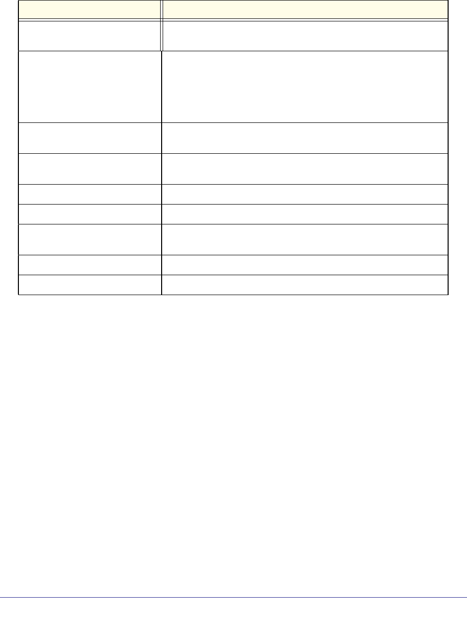
Appendix A. Supplemental Information | 97
NETGEAR N300 Wireless Router with External Antennas WNR1500 User Manual
Specifications
Table 2. Router Technical Specifications
Feature Specification
Data and routing protocols TCP/IP, RIP-1, RIP-2, DHCP, PPPoE, PPTP, Bigpond, Dynamic DNS,
and UPnP
Power adapter • North America: 120V, 60 Hz, input
• UK, Australia: 240V, 50 Hz, input
• Europe: 230V, 50 Hz, input
• Japan: 100V, 50/60 Hz, input
• All regions (output): 12V DC @ 1.0A, output
Dimensions 6.8" x 4.6" x 1.4"
172.7 x 115.7 x 32.6 mm
Weight 0.48 lbs.
0.216 kg
Operating temperature 0° to 40° C (32º to 104º F)
Operating humidity 90% maximum relative humidity, noncondensing
Designed to conform to the
following standards
CCC
SRRC
LAN 10BASE-T or 100BASE-Tx, RJ-45
WAN 10BASE-T or 100BASE-Tx, RJ-45

Appendix B. Notification of Compliance | 98
B
B. Notification of Compliance
Regulatory Compliance Information
This section includes user requirements for operating this product in accordance with National
laws for usage of radio spectrum and operation of radio devices. Failure of the end-user to
comply with the applicable requirements may result in unlawful operation and adverse action
against the end-user by the applicable National regulatory authority.
This product's firmware limits operation to only the channels allowed in a particular Region or
Country. Therefore, all options described in this user's guide may not be available in your
version of the product.
FCC Requirements for Operation in the United States
FCC Information to User
This product does not contain any user serviceable components and is to be used with
approved antennas only. Any product changes or modifications will invalidate all applicable
regulatory certifications and approvals
This device complies with Part 15 of the FCC Rules. Operation is subject to the following two
conditions: (1) This device may not cause harmful interference, and (2) this device must
accept any interference received, including interference that may cause undesired operation.
FCC Guidelines for Human Exposure
This equipment complies with FCC radiation exposure limits set forth for an uncontrolled
environment. This equipment should be installed and operated with minimum distance of 20
cm between the radiator and your body.
This transmitter must not be co-located or operating in conjunction with any other antenna or
transmitter.
FCC Declaration Of Conformity
We, NETGEAR, Inc., 350 East Plumeria Drive, San Jose, CA 95134, declare under our sole
responsibility that the N300 Wireless Router with External Antennas WNR1500 complies
with Part 15 of FCC Rules.
Operation is subject to the following two conditions:
•This device may not cause harmful interference, and

Appendix B. Notification of Compliance | 99
NETGEAR N300 Wireless Router with External Antennas WNR1500 User Manual
•This device must accept any interference received, including interference that may cause
undesired operation.
FCC Radio Frequency Interference Warnings & Instructions
This equipment has been tested and found to comply with the limits for a Class B digital
device, pursuant to Part 15 of the FCC Rules. These limits are designed to provide
reasonable protection against harmful interference in a residential installation. This
equipment uses and can radiate radio frequency energy and, if not installed and used in
accordance with the instructions, may cause harmful interference to radio communications.
However, there is no guarantee that interference will not occur in a particular installation.
If this equipment does cause harmful interference to radio or television reception, which can
be determined by turning the equipment off and on, the user is encouraged to try to correct
the interference by one or more of the following methods:
•Reorient or relocate the receiving antenna.
•Increase the separation between the equipment and the receiver.
•Connect the equipment into an electrical outlet on a circuit different from that which the
radio receiver is connected.
•Consult the dealer or an experienced radio/TV technician for help.
Modifications made to the product, unless expressly approved by NETGEAR, Inc., could void
the user's right to operate the equipment.
Canadian Department of Communications Radio Interference Regulations
This digital apparatus, N300 Wireless Router with External Antennas WNR1500, does not
exceed the Class B limits for radio-noise emissions from digital apparatus as set out in the Radio
Interference Regulations of the Canadian Department of Communications.
This Class [B] digital apparatus complies with Canadian ICES-003.
Cet appareil numérique de la classe [B] est conforme à la norme NMB-003 du Canada
European Union
The N300 Wireless Router with External Antennas WNR1500 complies with essential
requirements of EU EMC Directive 2004/108/EC and Low Voltage Directive 2006/95/EC as
supported by applying the following test methods and standards:
•EN55022: 2006 / A1: 2007
•EN55024: 1998 / A1: 2001 / A2 : 2003
•EN60950-1: 2005 2nd Edition
•EN 61000-3-2:2006
•EN 61000-3-3:1995 w/A1: 2001+A2: 2005
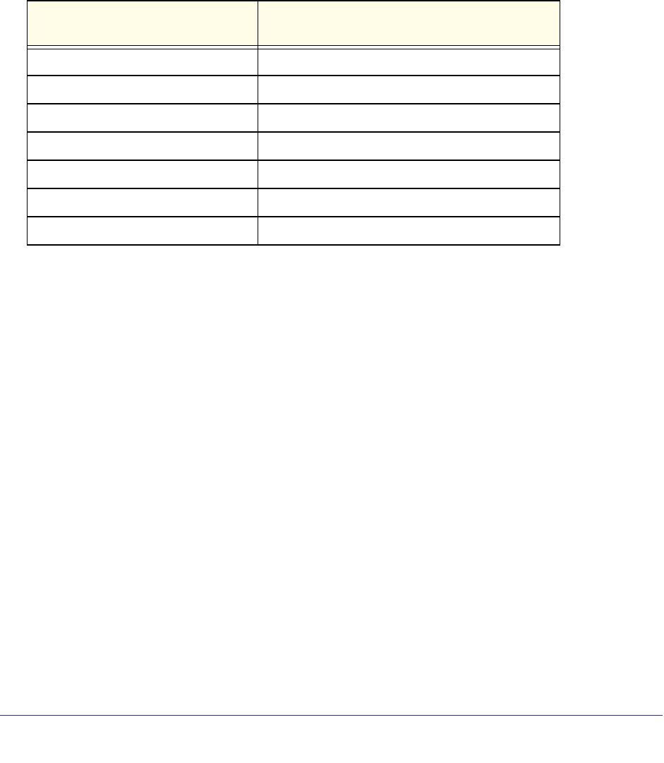
100 | Appendix B. Notification of Compliance
NETGEAR N300 Wireless Router with External Antennas WNR1500 User Manual
GPL License Agreement
GPL may be included in this product; to view the GPL license agreement go to
ftp://downloads.netgear.com/files/GPLnotice.pdf
For GNU General Public License (GPL) related information, please visit
http://support.netgear.com/app/answers/detail/a_id/2649
Interference Reduction Table
The table below shows the Recommended Minimum Distance between NETGEAR equipment and household
appliances to reduce interference (in feet and meters).
Household Appliance Recommended Minimum Distance
(in feet and meters)
Microwave ovens 30 feet / 9 meters
Baby Monitor - Analog 20 feet / 6 meters
Baby Monitor - Digital 40 feet / 12 meters
Cordless phone - Analog 20 feet / 6 meters
Cordless phone - Digital 30 feet / 9 meters
Bluetooth devices 20 feet / 6 meters
ZigBee 20 feet / 6 meters

Index | 102
Index
A
access
blocking 39
remote 61
restricting by MAC address 71
viewing logs 45
access control
turning on 73
access points 81
adding
custom service 48
priority rules 76
reserved IP addresses 68
static routes 74
See also configuring
addresses, DNS 24
advanced wireless settings 70
advertisement period 80
AES (Advanced Encryption Standard) encryption 34
alerts, emailing 44
Application Level Gateway (ALG), disabling 65
applications, QoS for 76
attached devices, viewing 61
automatic firmware checking 54
automatic Internet connection 21
B
back panel 9
backing up configuration 56
base station, setting up 82
Basic Settings screen
described 22
blocking
access 39
inbound traffic 46
blocking keywords, examples 40
blocking settings examples 40
box contents 7
C
cables, checking 86
cabling
Ethernet 11
channel, frequency 33
communication mode 33
compliance 98
configuration file
backing up 56
erase 57
erasing 57
managing 56
restoring 57
configuring
advanced security 70
Dynamic DNS 66
LAN IP settings 67
NAT 65
port forwarding 47
port triggering 47, 50
repeater unit 83
See also adding
connecting wirelessly 10
connection mode 23
content filtering 38
country setting 21
CTS/RTS Threshold 70
custom service (port forwarding) 48
D
date and time, troubleshooting 92
daylight savings time 43, 93
default factory settings
restoring 57, 94
deleting configuration 57
denial of service (DoS)
port scans 64
protection 38
device name 68
devices, adding 30
DHCP server 68
disable SSID 28

Index | 103
NETGEAR N300 Wireless Router with External Antennas WNR1500 User Manual
disabling
firewalls 24
router PIN 71
SIP ALG 65
SSID broadcast 28
wireless client association 82
Domain Name Server (DNS) addresses 24
Domain Name Server (DNS), secondary 24
DSL port settings 58
Dynamic DNS 65
DynDNS.org 66
E
email notices 44
encryption keys 36
erasing configuration 57
erasing configuration file 57
Ethernet cable 11
F
factory default settings
restoring 57, 94
factory settings
resetting 7
filtering content 38
firewalls
outbound rules 40
firmware
automatic check 54
restoring 87
upgrade 54
upgrade at log in 18
upgrade manually 55
Fragmentation Threshold 70
frequency, channel 33
front panel 8
LEDs described 8
G
games, QoS for 76
gateway IP address 24
generating encryption keys 36
H
host name 22
host trusted 40
I
inbound traffic, allowing or blocking 46
installing
Setup Wizard 21
Internet port 21
Internet port, no connection 25
Internet Service Provider (ISP), see ISP
interval, poll 60
IP address
DHCP 16
LAN service 67
reserved 69
IP addresses
blocking access by 42
registering domain name 65
reserved 68
IP setup, LAN 67
ISP
account information 16
Basic Settings screen 22
ISP login 16
K
keys, encryption 36
keywords
blocking 39
deleting 40
L
L2TP 23
LAN
ports 59
LAN path, troubleshooting 91
LAN port
QoS for 77
language setting 21
LEDs
verifying cabling 14
Legacy mode 33
local servers, port forwarding to 47
logging in
changing password 25
ISP 16
router 17
types 26
upgrade firmware 18
login time-out 25
logs
viewing 45
logs, emailing 44

104 | Index
NETGEAR N300 Wireless Router with External Antennas WNR1500 User Manual
M
MAC addresses
described 28
QoS for 75, 78
restricting access by 71
spoofing 89
maintenance settings 53
managing router remotely 61
manual logout 26
Maximum Transmit Unit (MTU) 64
menus, described 19
metric value 74
mixed mode encryption 34
mixed mode security options 29
mode, communication 33
multicasting 68
N
NAT (Network Address Translation) 65
Neighbor Friendly mode 33
Network Address Translation (NAT) 24
Network Time Protocol (NTP) 42, 92
no Internet connection 25
O
On/Off LED 8
online games, QoS for 76
online help, router 19
Open System authentication 36
P
passphrases 35, 36
password
restoring 94
path, testing 92
Performance mode 34
PIN 71
ping 91
pinging WAN port 64
poll interval 60
port forwarding
configuring 47
port scanning, disabling 64
port status 59
port triggering
configuring 47, 50
portmap table 81
ports
filtering 40
listed, back panel 9
positioning the router 10
Power light, troubleshooting and 86
PPPoE 23
PPTP 23
PPTP (Point to Point Tunneling Protocol) 23
Preamble mode 70
primary DNS addresses 24
prioritizing traffic 74
Push ’N’ Connect 88
Q
QoS (Quality of Service) 74
R
radio, wireless 70
range of wireless connections 10
region of operation 33
remote devices, testing path 92
remote management 61
repeater units 83
replace existing router 16
reserved IP address 69
reserved IP adresses 68
restarting network 86
restore
configuration file 57
restoring
default factory settings 57, 94
restoring firmware 87
restricting access by MAC address 71
route name 74
router interface, described 19
router PIN 71
router, status 58
Routing Information Protocol (RIP} 67
S
secondary DNS 24
security 28
see also security options
security features 28
security options
described 29
settings 29
security PIN 31, 71

Index | 105
NETGEAR N300 Wireless Router with External Antennas WNR1500 User Manual
security settings 38
sending logs by email 44
service numbers 41
services 40
Session Initiation Protocol (SIP), disabling 65
setting time zone 42
settings, default. See default factory settings
Setup Wizard 21
Shared Key authentication 36
Simple Mail Transfer Protocol (SMTP) 44
sites, blocking 39
specifications
technical 95
spoofing MAC addresses 89
SSID 33
disable 28
static routes 73
statistics, viewing 59
status
Internet connection 60
router 58
T
TCP/IP
no Internet connection 25
TCP/IP network, troubleshooting 91
technical specifications 95
technical support 2
Temporal Key Integrity Protocol (TKIP) 29
time of day, troubleshooting 92
time to live, advertisement 80
time zone, setting 42
time-out
port triggering 51
time-stamping 43
TKIP (Temporal Key Integrity Protocol) encryption 34
trademarks 2
traffic metering 79
traffic, prioritizing 74
troubleshooting 85
trusted host 40
Trusted IP Address field 40
turn off wireless connectivity 28
U
Universal Plug and Play (UPnP) 80
upgrading firmware 54
V
viewing
advanced wireless settings 70
logs 45
Virtual Channel Identifier (VCI) 16
Virtual Path Identifier (VPI) 16
W
WAN 64
advanced setup 64
ping response 64
settings 64
WAN port
scanning 64
WAN setup 64
WDS 81, 82
WEP encryption 35
Wi-Fi Protected Setup (WPS) 30, 31, 88
adding devices 30
wildcards, DNS and 66
Wired Equivalent Privacy (WEP) encryption
when to use 29
Wireless Card Access List 71, 72
wireless connections 10
wireless connectivity 28
Wireless Distribution System (WDS) 81
wireless isolation 33
wireless network name 33
wireless port settings 59
wireless radio 70
wireless repeating 81, 82
base station 82
repeater unit 83
wireless repeating function 81, 82
wireless security options 29
wireless settings
advanced 70
Wireless Settings screen 31
wireless settings, SSID broadcast 33
WMM (Wi-Fi Multimedia) 75
WPA encryption 29
WPA2 encryption 29
WPA2-PSK encryption 29
WPA-PSK encryption 29
WPA-PSK/WPA2-PSK mixed mode 29
WPS button 30
WPS-PSK encryption 29
WPS-PSK+ WPA2-PSK encryption 29