Netgear orporated 13200232 N450 Wireless Router User Manual N450 Wireless Router WNR2500
Netgear Incorporated N450 Wireless Router N450 Wireless Router WNR2500
UserManual.wiki
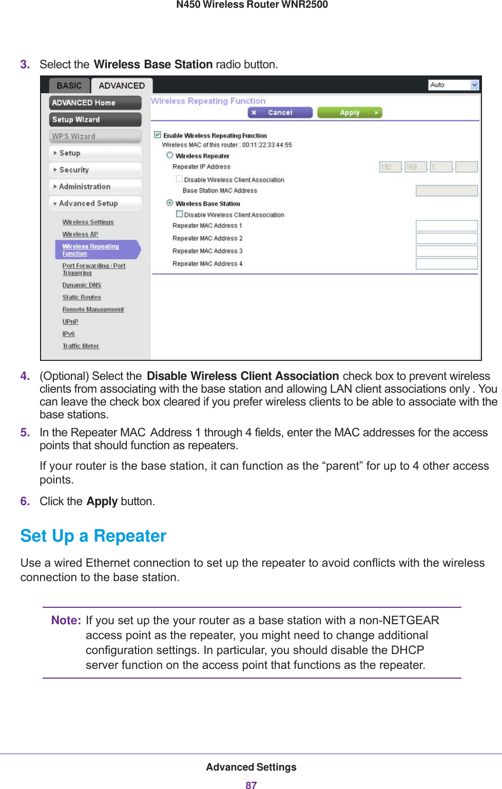
>
Netgear orporated
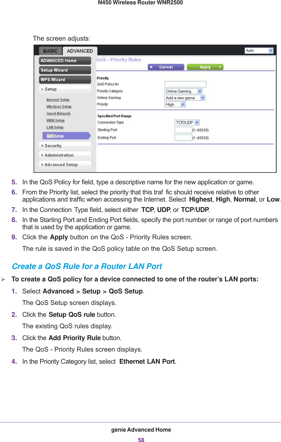
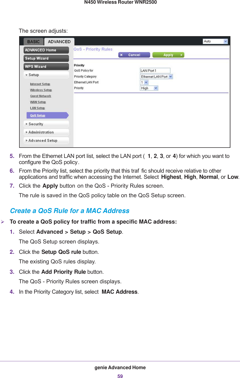
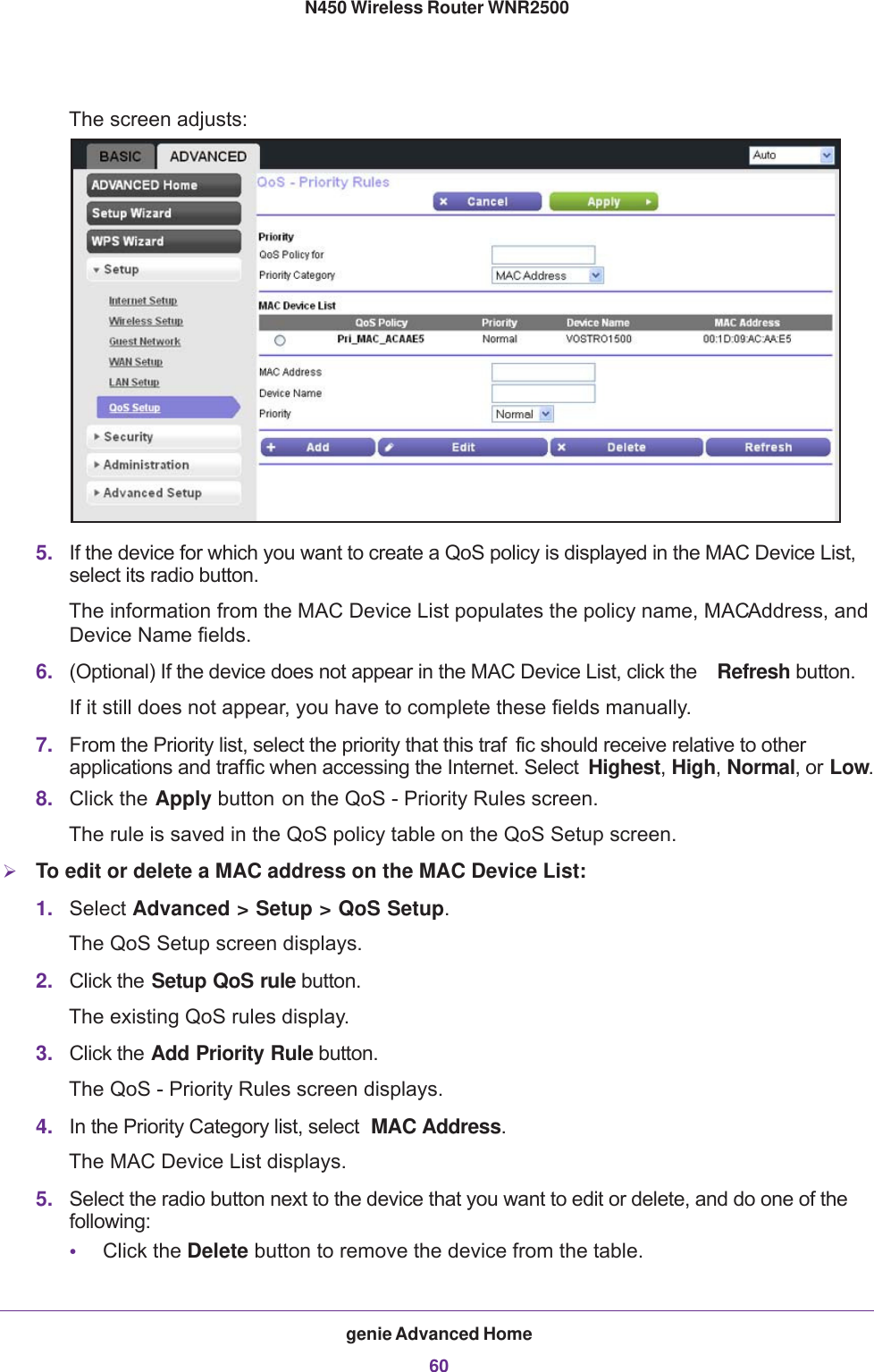
>
13200232 User Manual
Users Manual
Navigation menu
Upload a User Manual
Namespaces
Wiki Guide
HTML
PDF
Info
Views
User Manual
Discussion / Help
Navigation


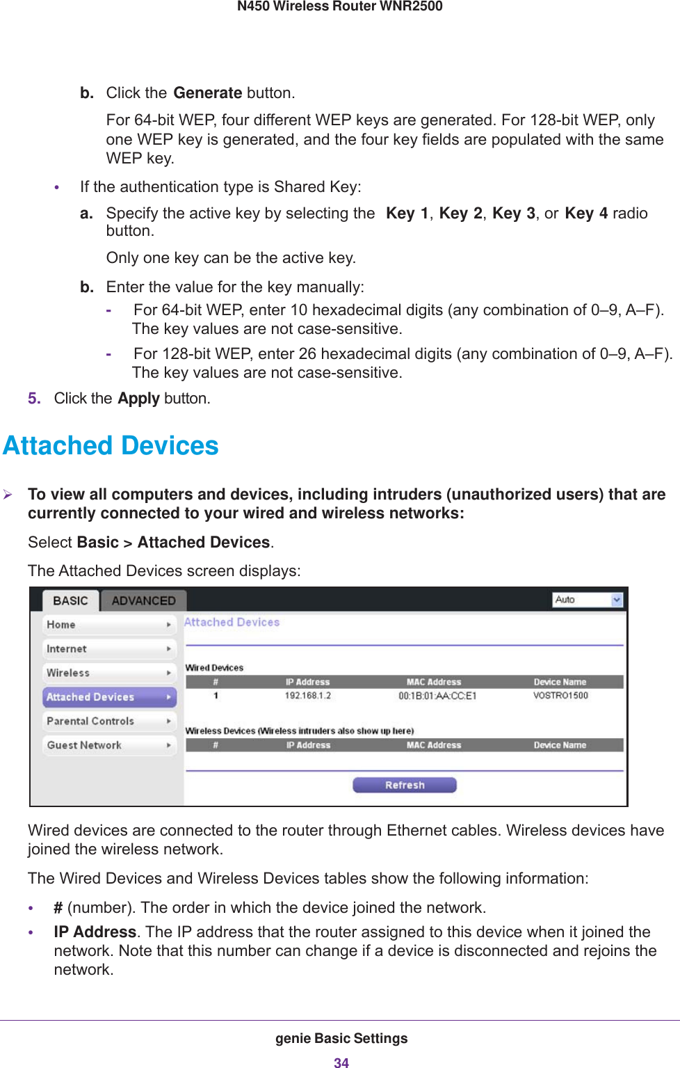
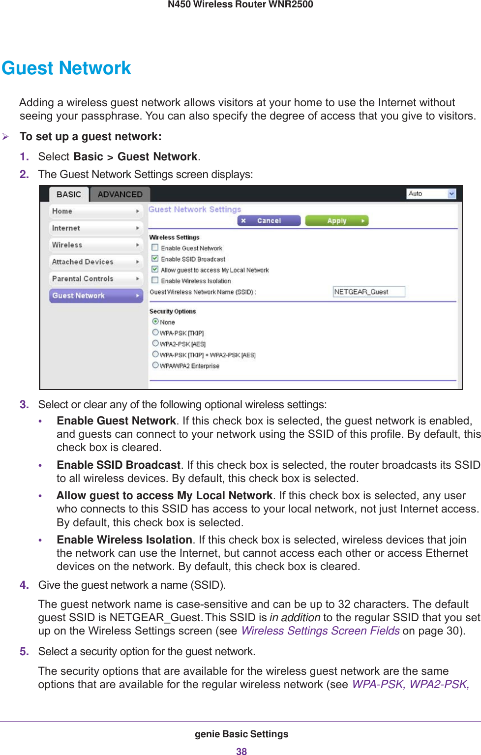
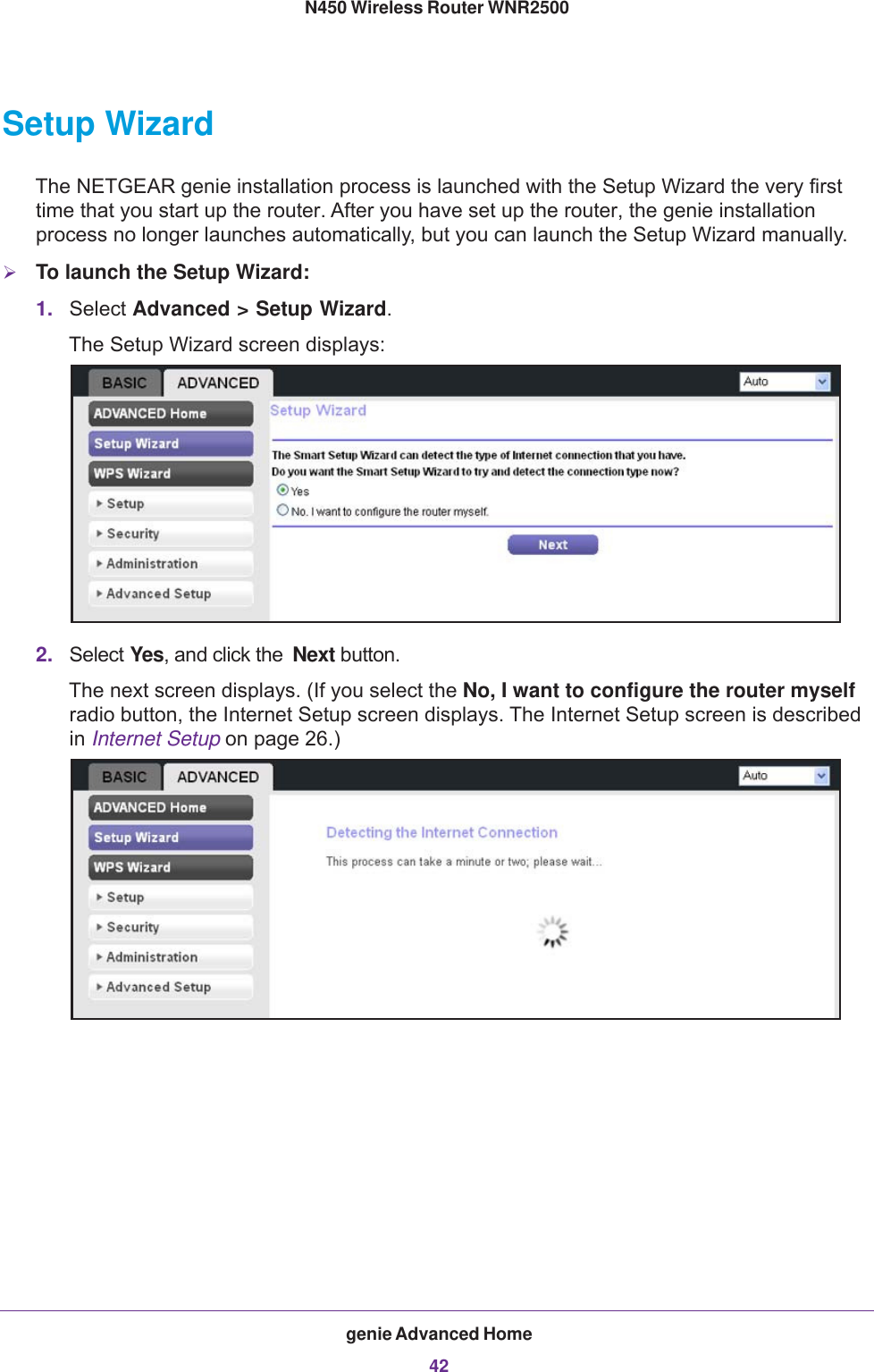
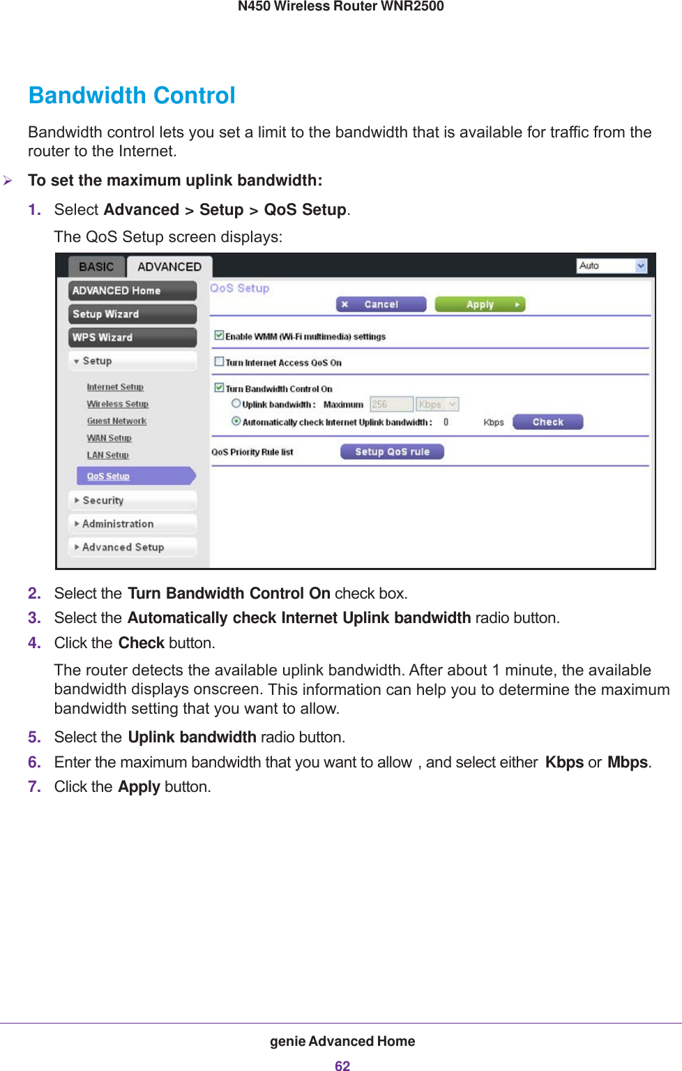
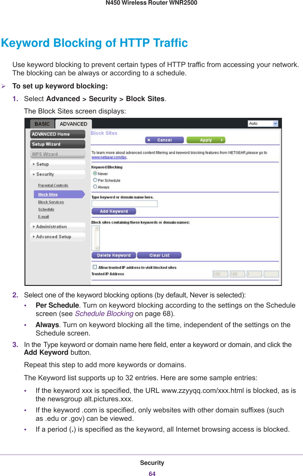
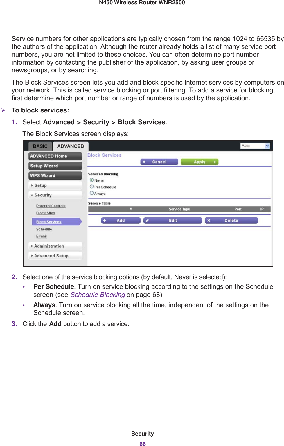
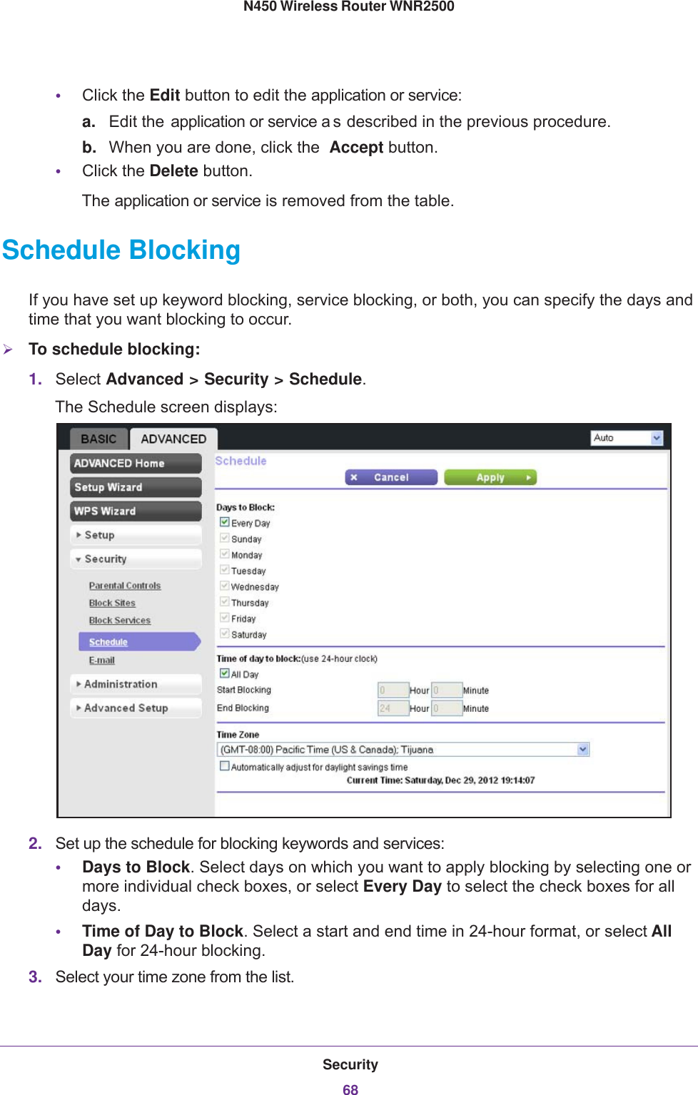
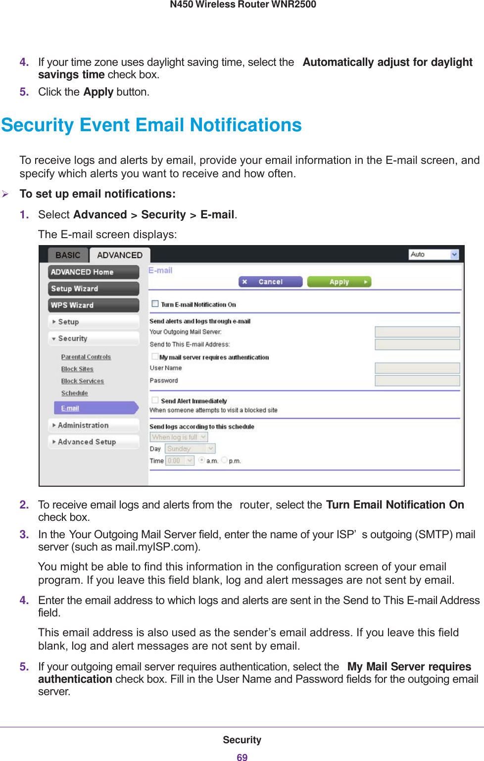
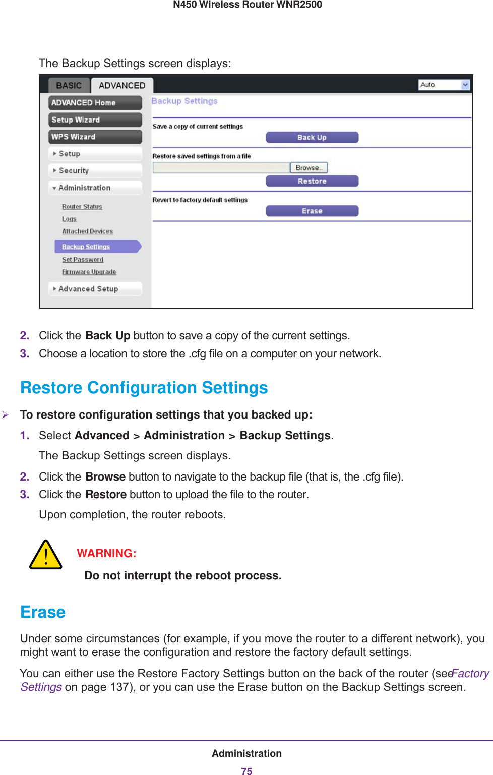
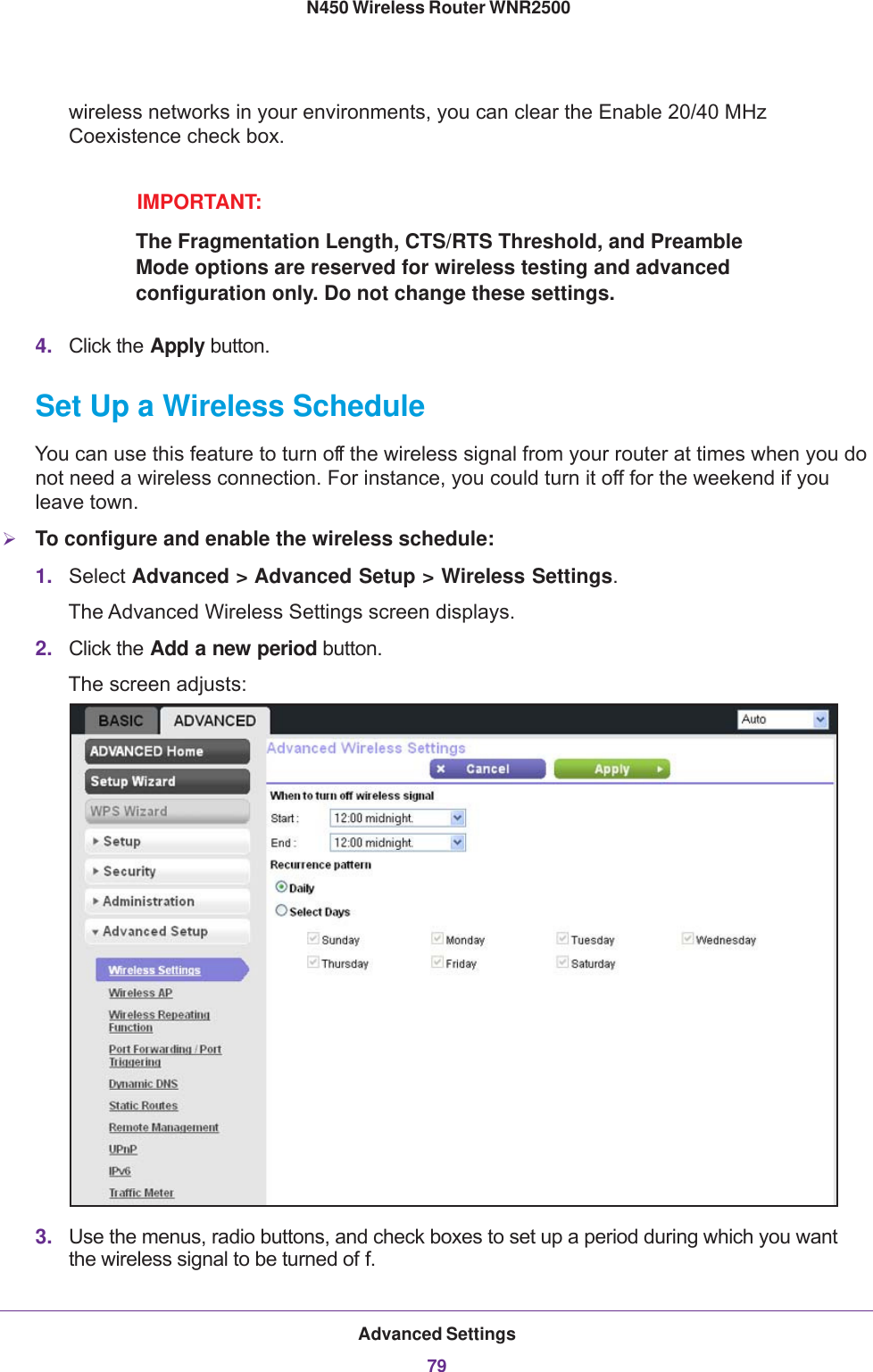
![genie Basic Settings31 N450 Wireless Router WNR2500WARNING:NETGEAR recommends that you do not change the wireless security option and the passphrase. However, if you need to change these settings, the following sections explains how. Do not disable wireless security!WPA-PSK, WPA2-PSK, and WPA-PSK + WPA2-PSK Mixed ModeThese types of wireless security options use a pre-shared key (PSK), which is the same as a passphrase, wireless network password, or network key.You can select from the following wireless PSK security options:•WPA-PSK [TKIP]. Wi-Fi Protected Access (WPA) provides strong data security with Temporal Key Integrity Protocol (TKIP) encryption. This option supports speeds of up to 54 Mbps only.•WPA2-PSK [AES]. Wi-Fi Protected Access version 2 (WPA2) provides strong data security with Advanced Encryption Standard (AES) encryption. This is the preset wireless security that is enabled by default. WPA2 provides the most reliable security. This option supports speeds of up to 300 Mbps. If not all clients in your network support WPA2, select WPA-PSK + WPA2-PSK mixed mode.•WPA-PSK [TKIP] + WPA2-PSK [AES]. WPA-PSK + WPA2-PSK is referred to as mixed mode, which supports a combination of TKIP and AES encryption for both WPA and WPA2 clients. For WPA clients, this option supports speeds of up to 54 Mbps only. For WPA2 clients, this option supports speeds of up to 300 Mbps.To change the WPA wireless security option and passphrase:1. In the Security Options sections of the Wireless Settings screen, select one of the WP A options with PSK.2. In the associated Passphrase field, enter the passphrase that you want to use. The passphrase is a text string from 8 to 63 ASCII characters or exactly 64 hexadecimal digits. A hexadecimal digit is one of the following characters: 0, 1, 2, 3, 4, 5, 6, 7, 8, 9, A, B, C, D, E, and F.](https://usermanual.wiki/Netgear-orporated/13200232/User-Guide-2021307-Page-31.png)
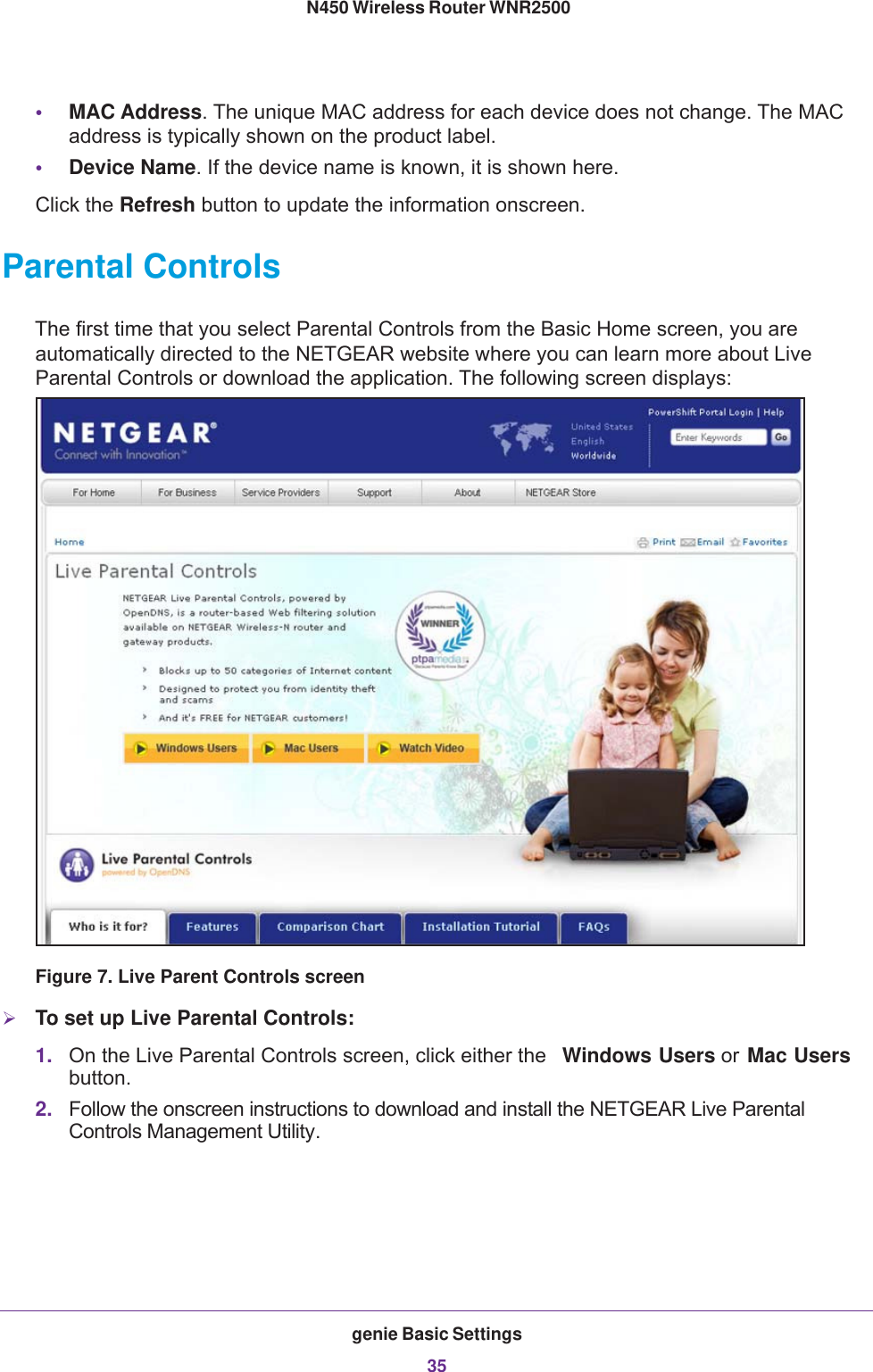
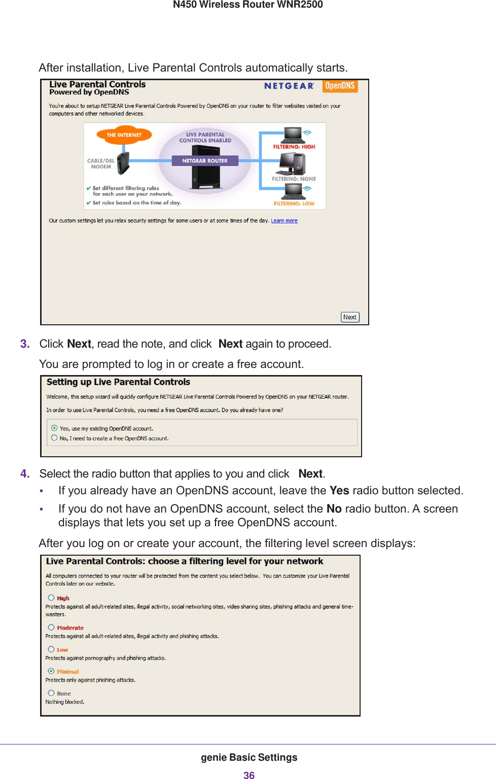
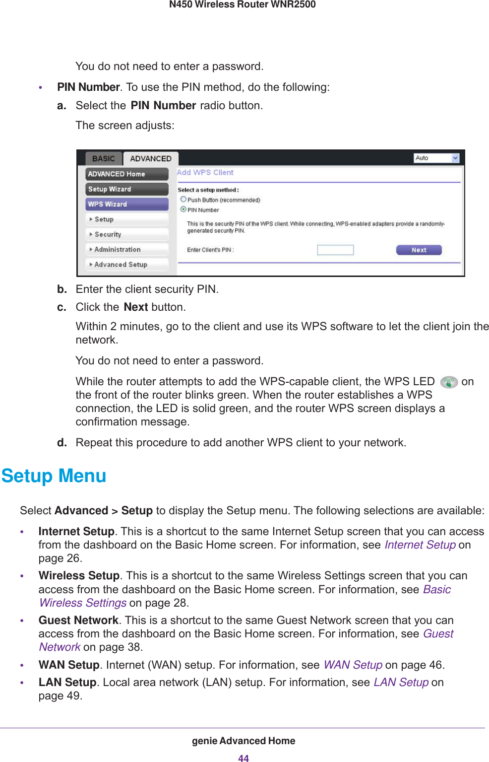
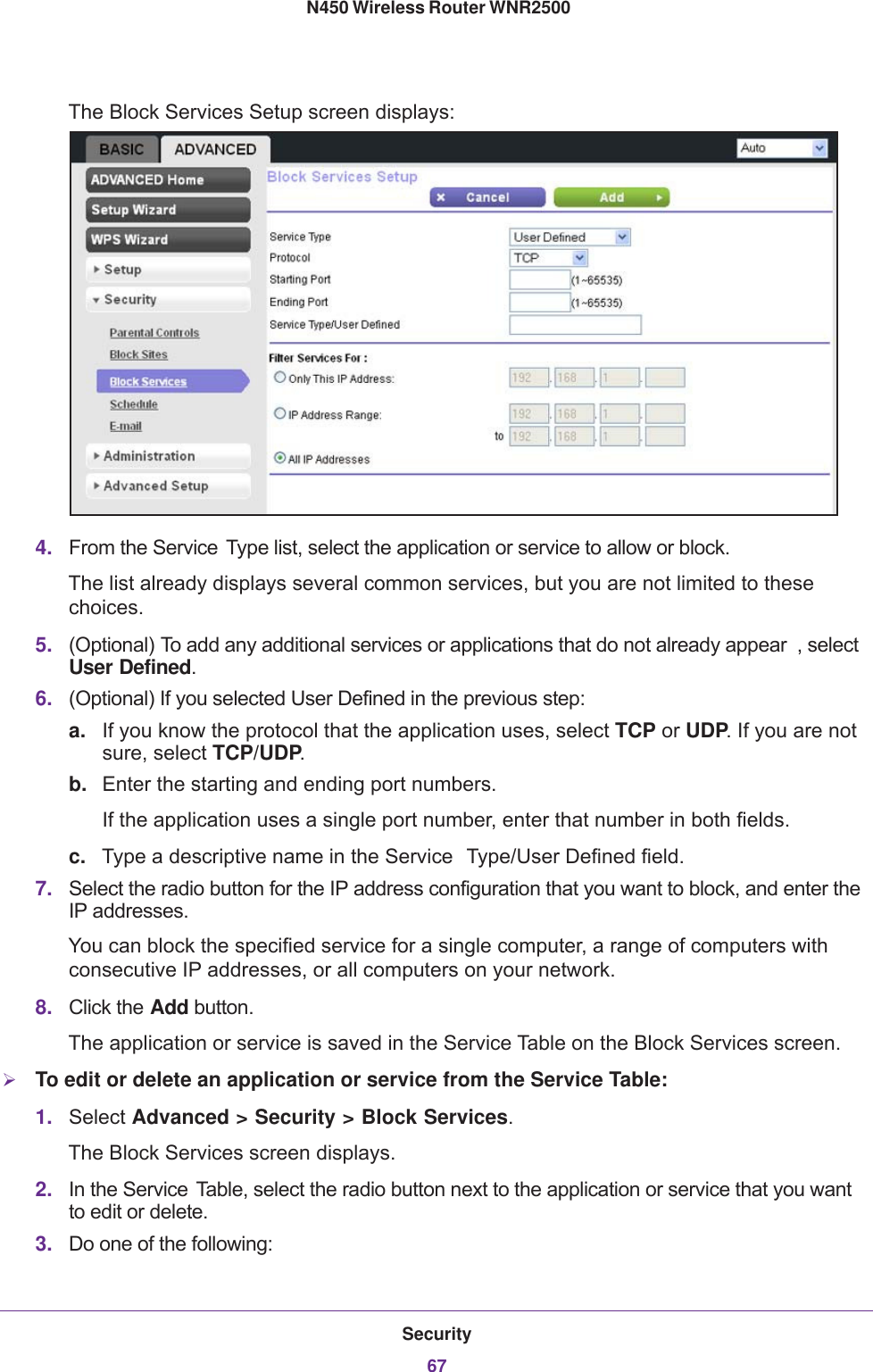
![genie Basic Settings32N450 Wireless Router WNR2500 Wireless clients need to use the passphrase to access the wireless network through the router.3. Click the Apply button.WPA/WPA2 EnterpriseThis security option is not for home use but is typically used in a business or enterprise. WPA/WPA2 Enterprise does not use a passphrase but supports 802.1x authentication, which requires an internal or external RADIUS server. A Remote Authentication Dial In User Service (RADIUS) server provides Authentication, Authorization, and Accounting (AAA) management to grant (or deny) computers access to your wireless network.WPA/WPA2 Enterprise can support WPA [TKIP] for WPA clients only, WPA2 [AES] for WPA2 clients only, and WPA [TKIP] + WPA2 [AES], which is a combination of TKIP and AES encryption for both WPA and WPA2 clients. WPA clients are supported at speeds of up to 54 Mbps only. WPA2 clients are supported at speeds of up 300 Mbps.WPA/WPA2 Enterprise supports five Extensible Authentication Protocol (EAP) authentication methods: EAP-TLS, EAP-TTLS/MSCHAPv2, PEAPv0/EAP-MSCHAPv2, PEAPv1/EAP-GTC, and EAP-SIM.To configure WPA/WPA2 Enterprise security:1. In the Security Options sections of the Wireless Settings screen, select the WPA/WPA2 Enterprise radio button.2. Select the WPA mode (WPA [TKIP], WPA2 [AES], or WPA [TKIP] + WPA2 [AES]).3. Type the IP address of the RADIUS server .The address can be on your LAN on it can be an external address.4. Enter the port number for the RADIUS server in the range from 1 to 65535 (the default number is 1812).5. Type the shared secret, which needs to b e between 1 and 128 characters (the default value is blank). The shared secret is case-sensitive.6. Click the Apply button.](https://usermanual.wiki/Netgear-orporated/13200232/User-Guide-2021307-Page-32.png)


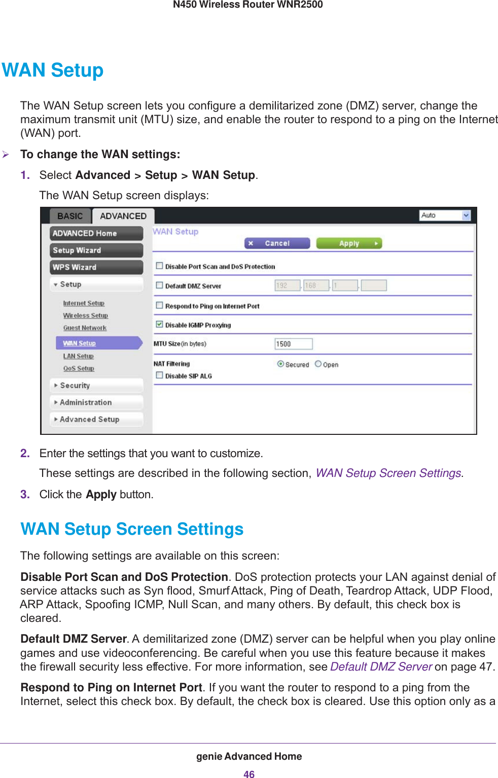


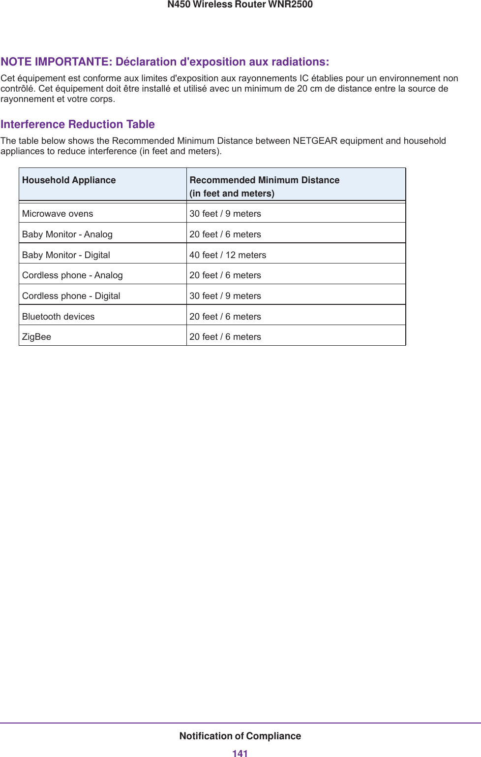
![Notification of Compliance140N450 Wireless Router WNR2500FCC Radio Frequency Interference Warnings & InstructionsThis equipment has been tested and found to comply with the limits for a Class B digital device, pursuant to Part 15 of the FCC Rules. These limits are designed to provide reasonable protection against harmful interference in a residential installation. This equipment uses and can radiate radio frequency energy and, if not installed and used in accordance with the instructions, may cause harmful interference to radio communications. However, there is no guarantee that interference will not occur in a particular installation. If this equipment does cause harmful interference to radio or television reception, which can be determined by turning the equipment off and on, the user is encouraged to try to correct the interference by one or more of the following methods:• Reorient or relocate the receiving antenna.• Increase the separation between the equipment and the receiver.• Connect the equipment into an electrical outlet on a circuit different from that which the radio receiver is connected.• Consult the dealer or an experienced radio/TV technician for help.FCC Caution• Any changes or modifications not expressly approved by the party responsible for compliance could void the user’s authority to operate this equipment. • This device complies with Part 15 of the FCC Rules. Operation is subject to the following two conditions: (1) This device may not cause harmful interference, and (2) this device must accept any interference received, including interference that may cause undesired operation. • For product available in the USA market, only channel 1~11 can be operated. Selection of other channels is not possible.• This device and it's antennas(s) must not be co-located or operating in conjunction with any other antenna or transmitter except in accordance with FCC multi-transmitter product procedures..TV Tuner (on Selected Models)Note to CATV System Installer: This reminder is provided to call the CATV system installer’s attention to Section 820-93 of the National Electrical Code, which provides guidelines for proper grounding and, in particular, specifies that the Coaxial cable shield be connected to the grounding system of the building as close to the point of cable entry as possible. Canadian Department of Communications Radio Interference RegulationsThis digital apparatus (N450 Wireless Router WNR2500) does not exceed the Class B limits for radio-noise emissions from digital apparatus as set out in the Radio Interference Regulations of the Canadian Department of Communications.This Class [B] digital apparatus complies with Canadian ICES-003.Cet appareil numérique de la classe [B] est conforme à la norme NMB-003 du CanadaIndustry CanadaThis device complies with RSS-210 of the Industry Canada Rules. Operation is subject to the following two conditions: (1) This device may not cause harmful interference, and (2) this device must accept any interference received, including interference that may cause undesired operation.Ce dispositif est conforme à la norme CNR-210 d'Industrie Canada applicable aux appareils radio exempts de licence. Son fonctionnement est sujet aux deux conditions suivantes: (1) le dispositif ne doit pas produire de brouillage préjudiciable, et (2) ce dispositif doit accepter tout brouillage reçu, y compris un brouillage susceptible de provoquer un fonctionnement indésirable.IMPORTANT NOTE: Radiation Exposure Statement:This equipment complies with IC radiation exposure limits set forth for an uncontrolled environment. This equipment should be installed and operated with minimum distance 20cm between the radiator & your body.](https://usermanual.wiki/Netgear-orporated/13200232/User-Guide-2021307-Page-140.png)