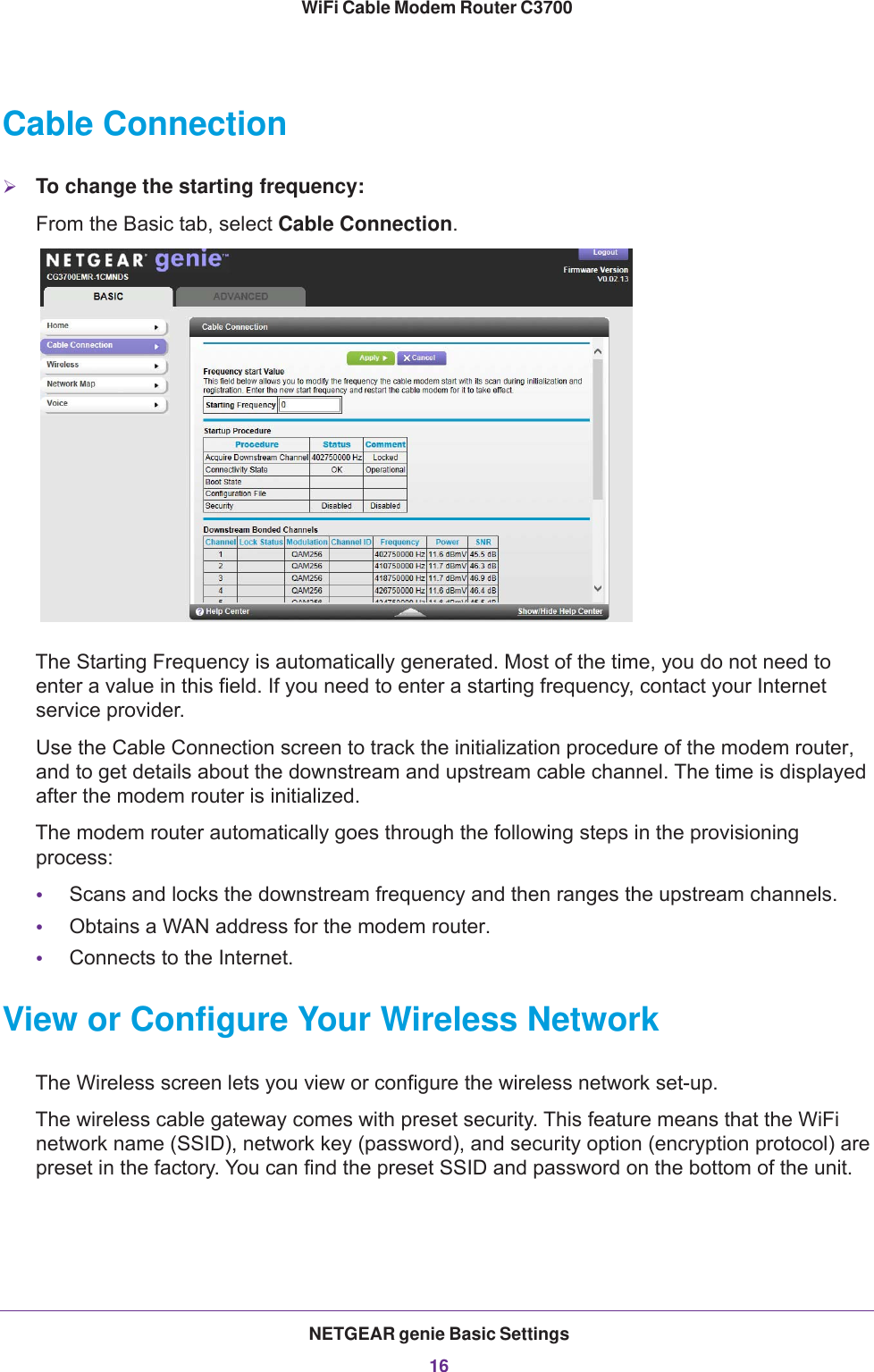
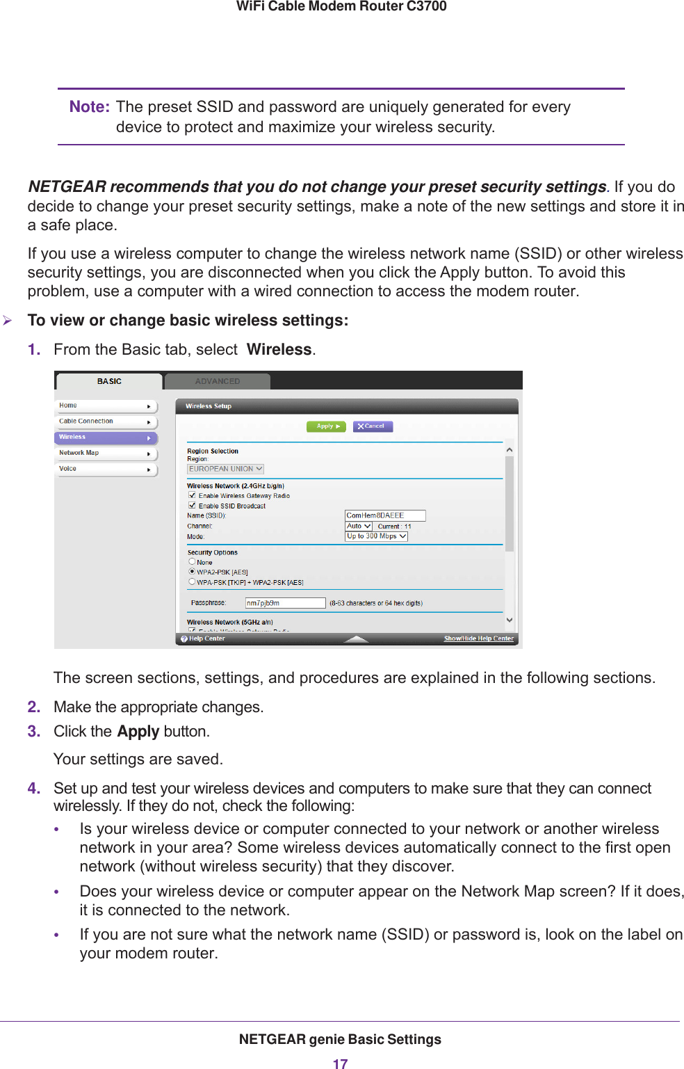
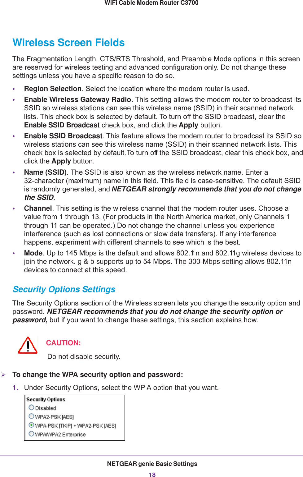
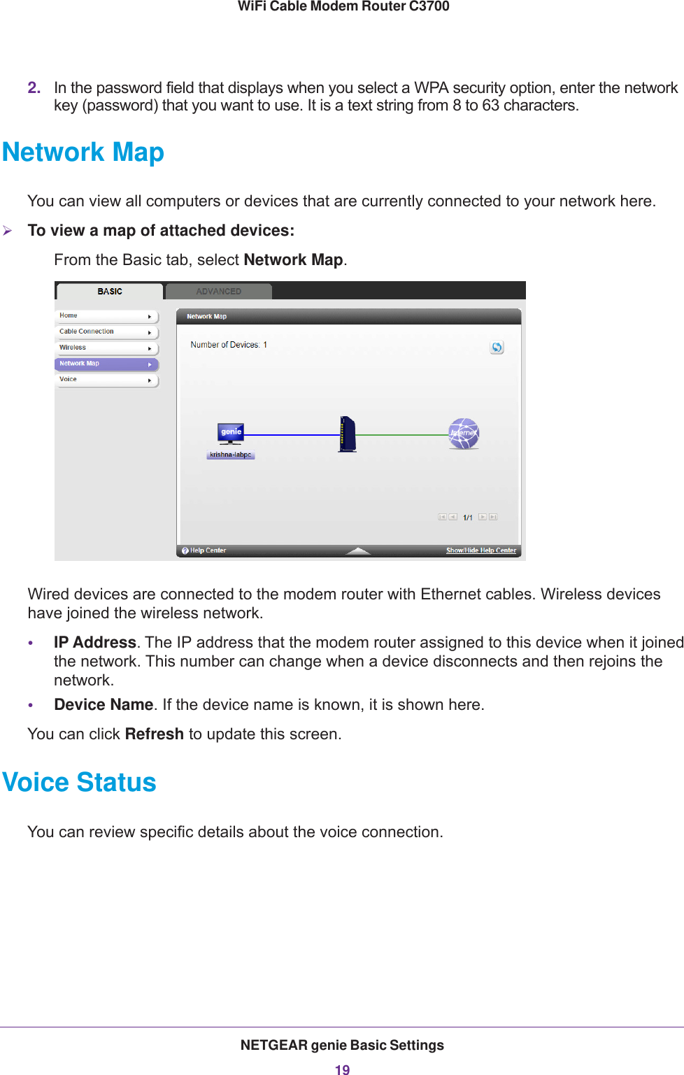
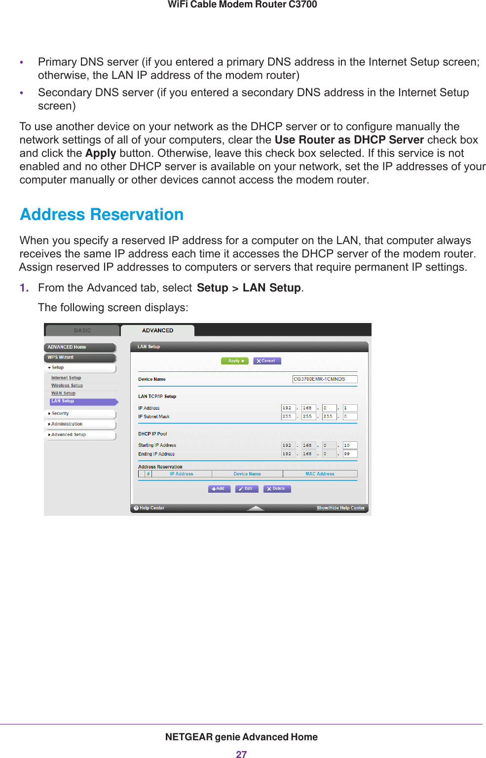
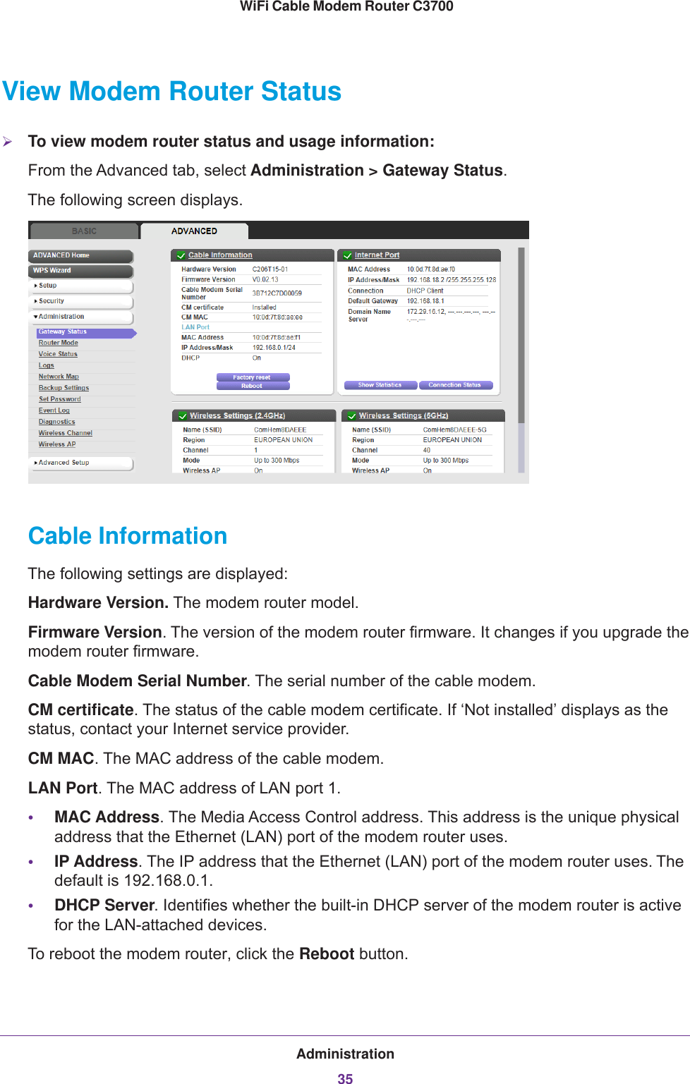
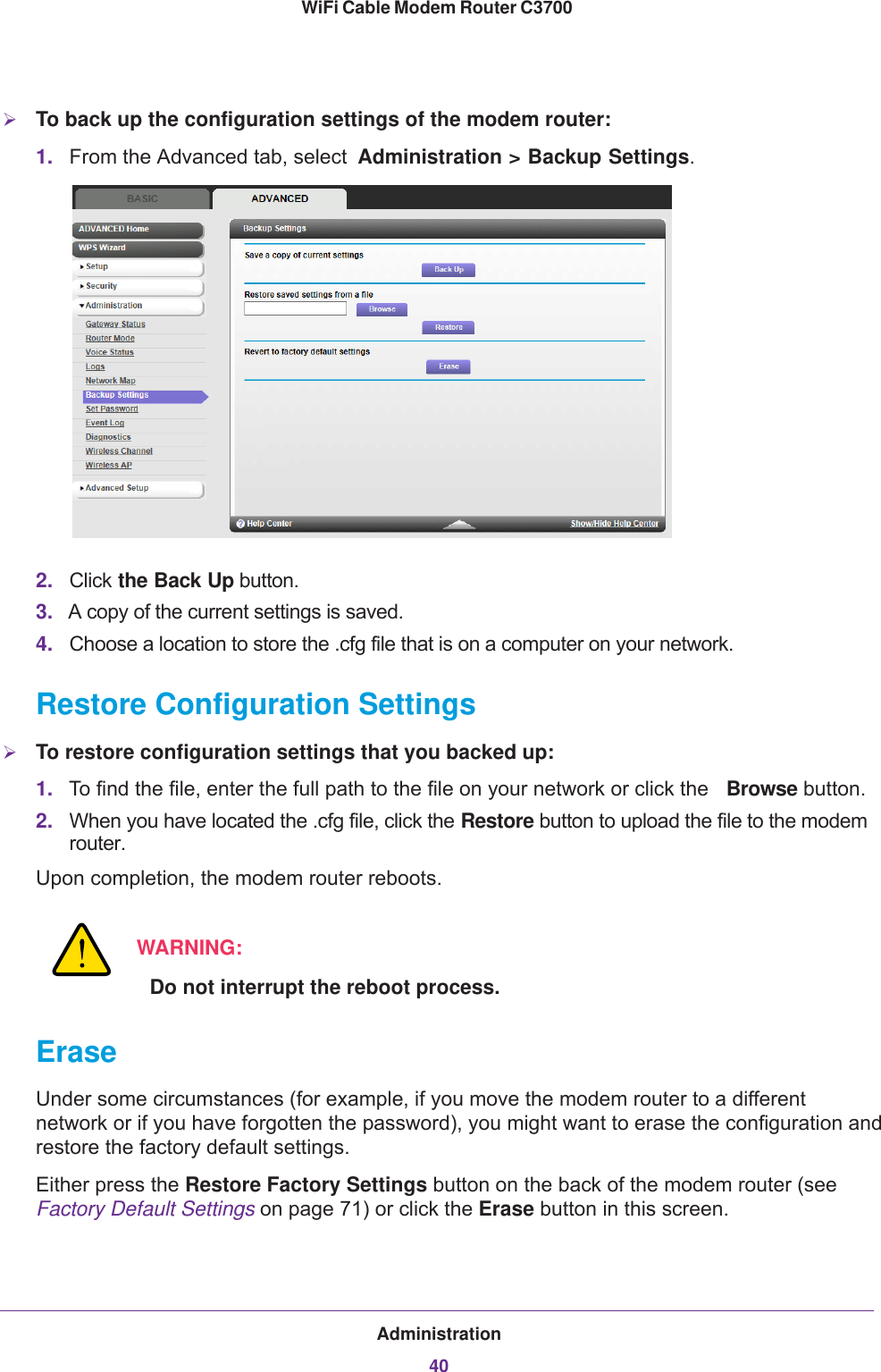
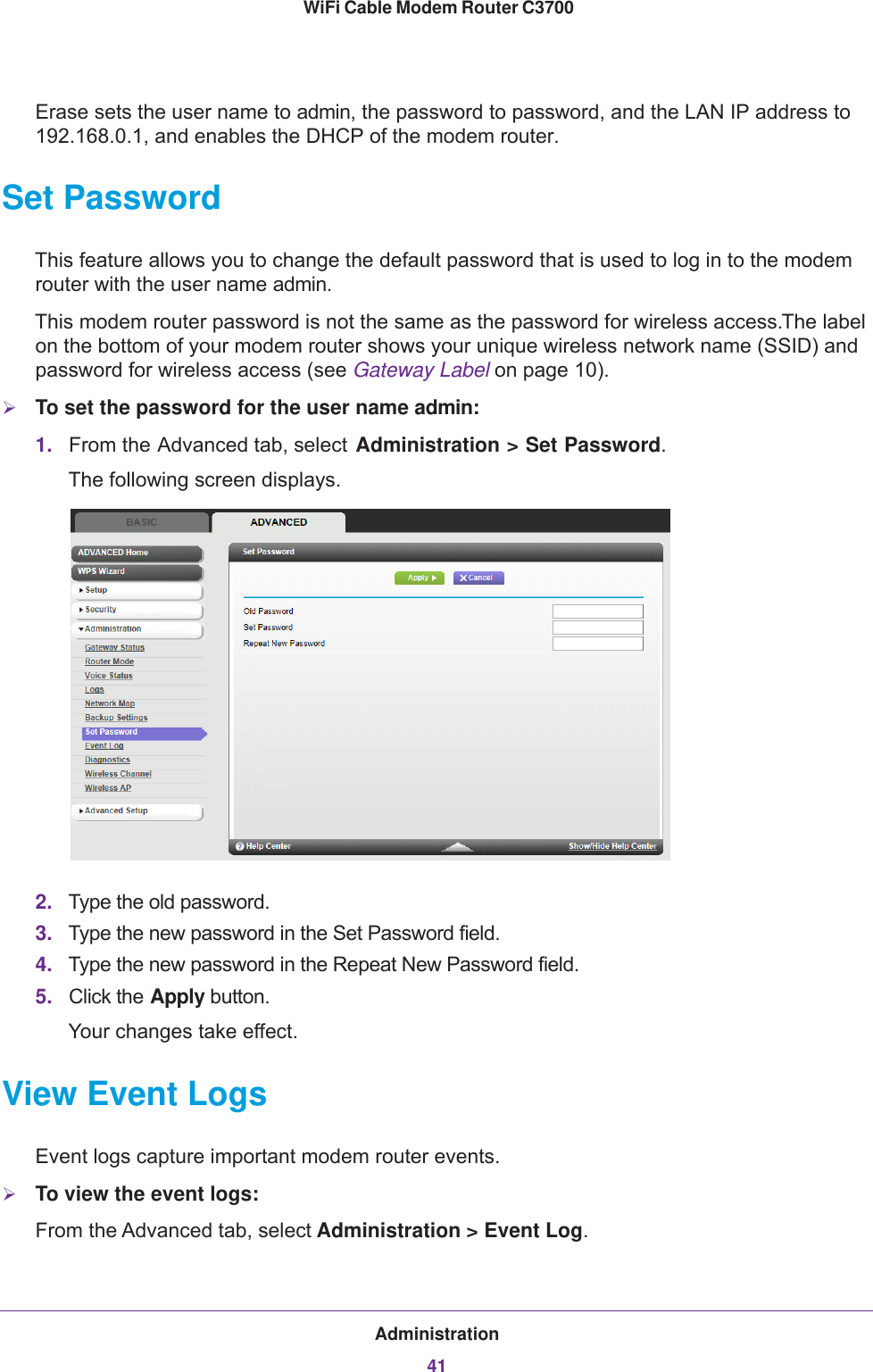
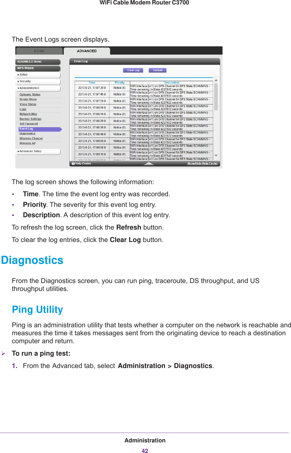
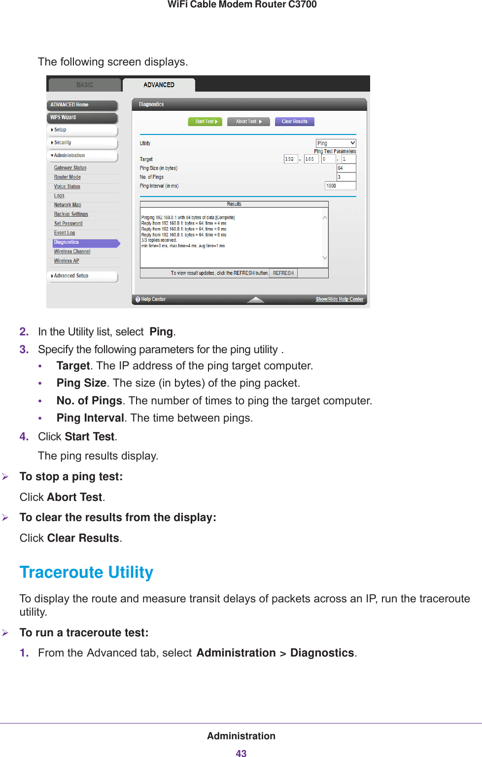
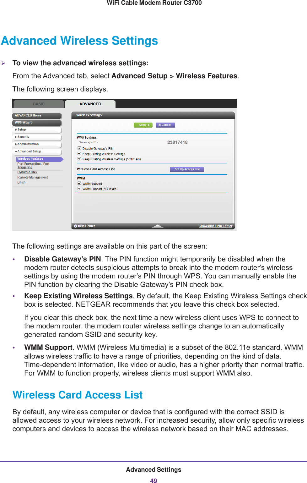
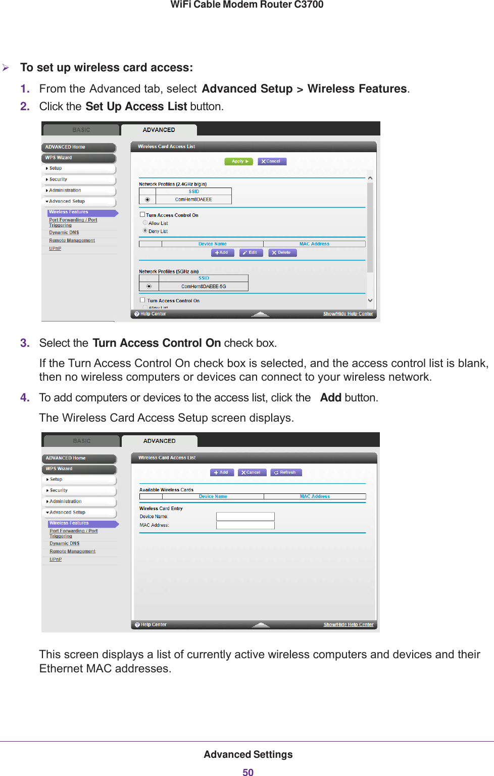
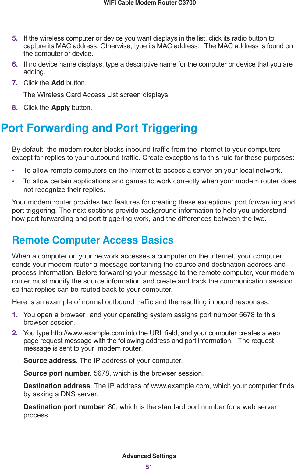
Netgear orporated 13300241 WiFi Cable Modem Router User Manual Wireless Cable Gateway CG3300CMR
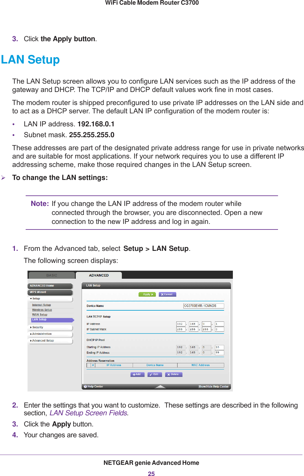
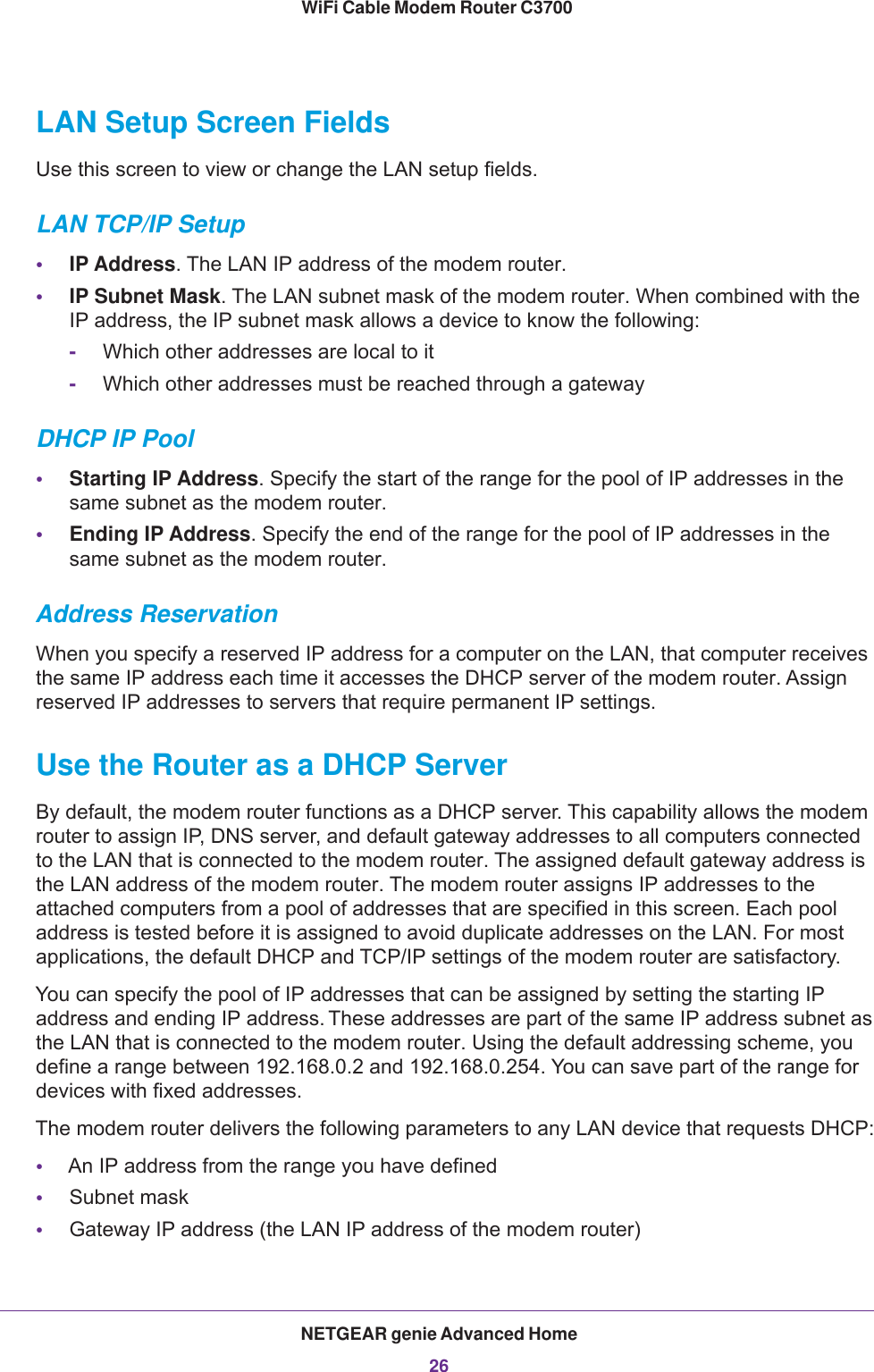
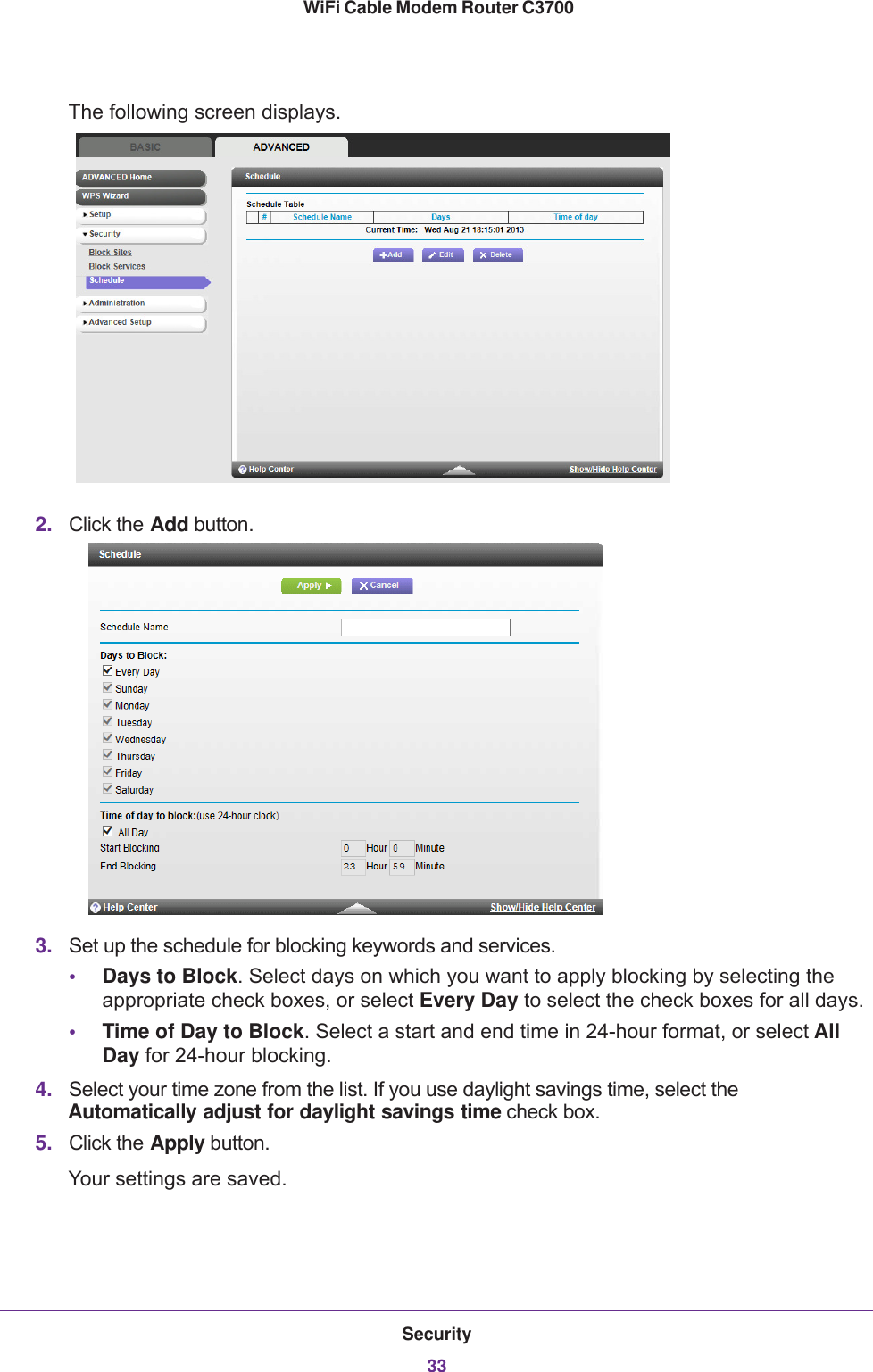
Netgear Incorporated WiFi Cable Modem Router Wireless Cable Gateway CG3300CMR
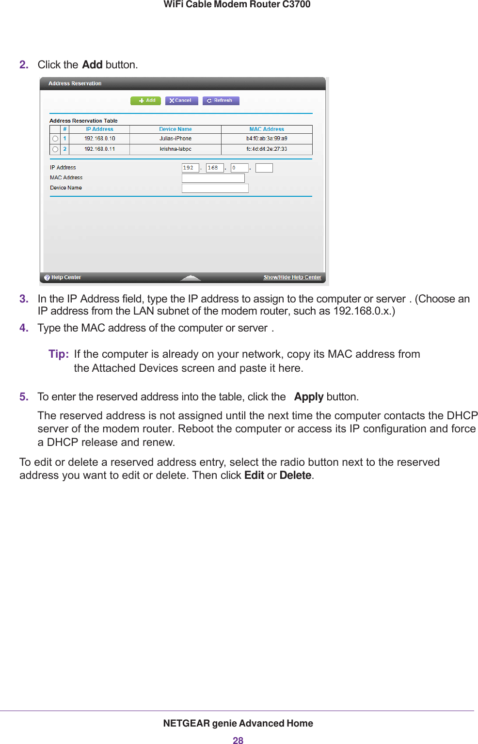
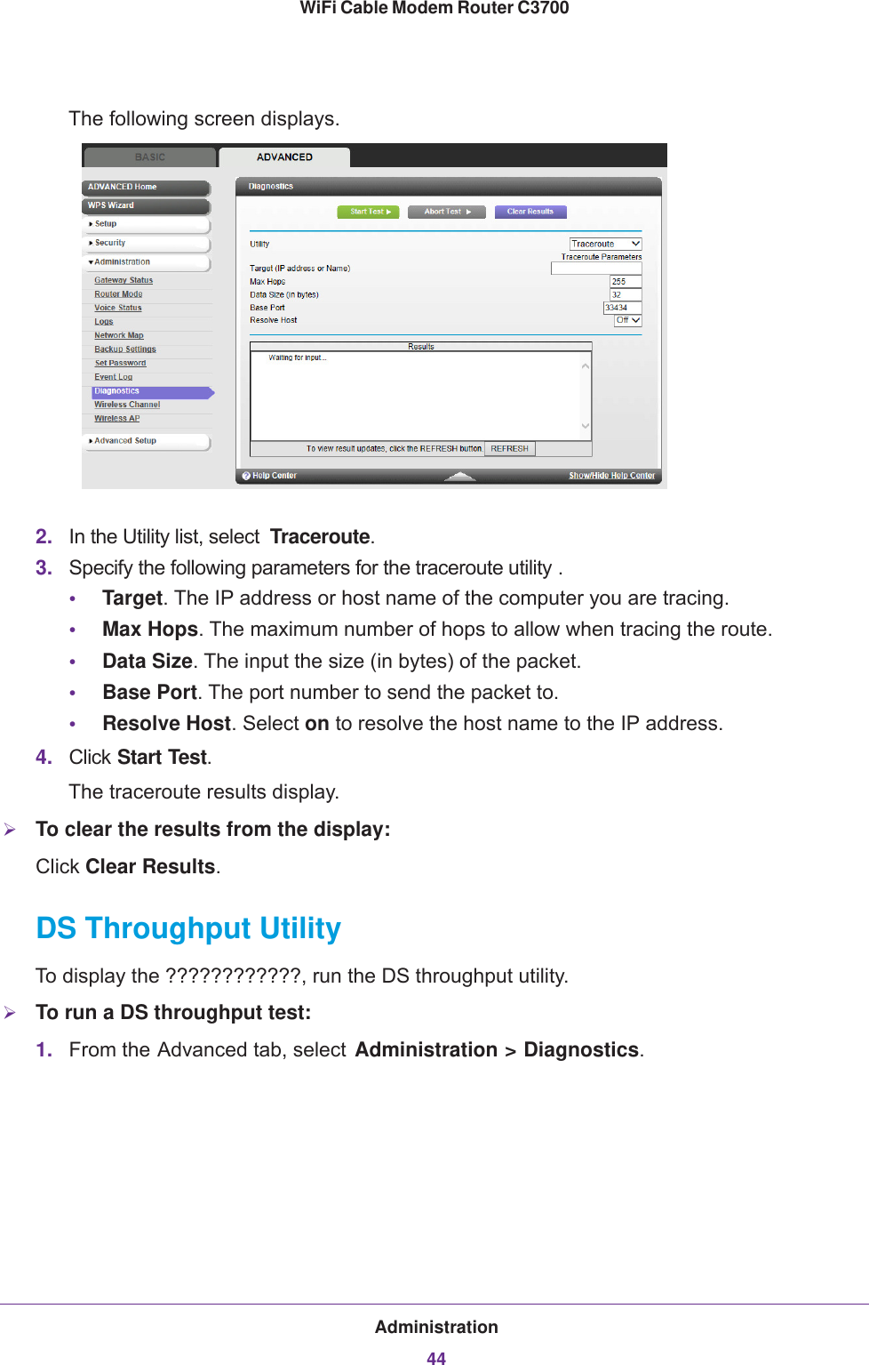
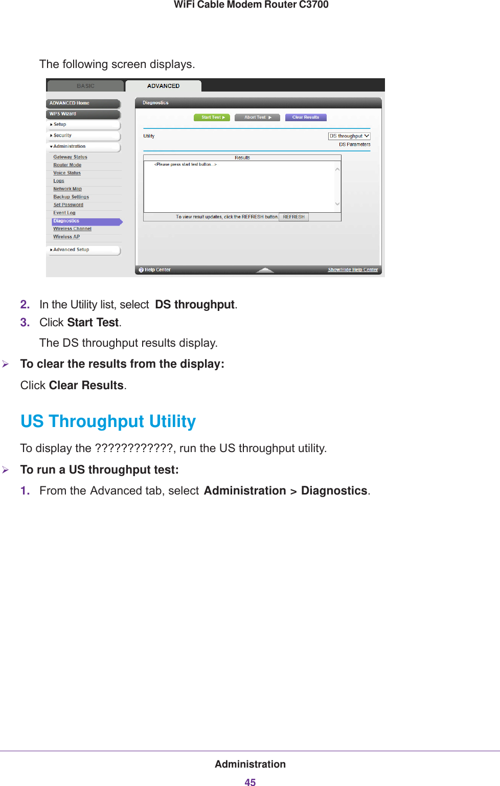
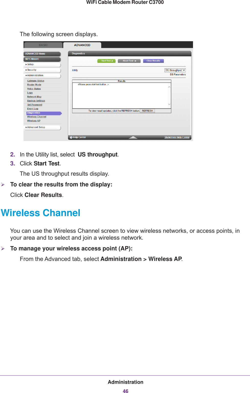
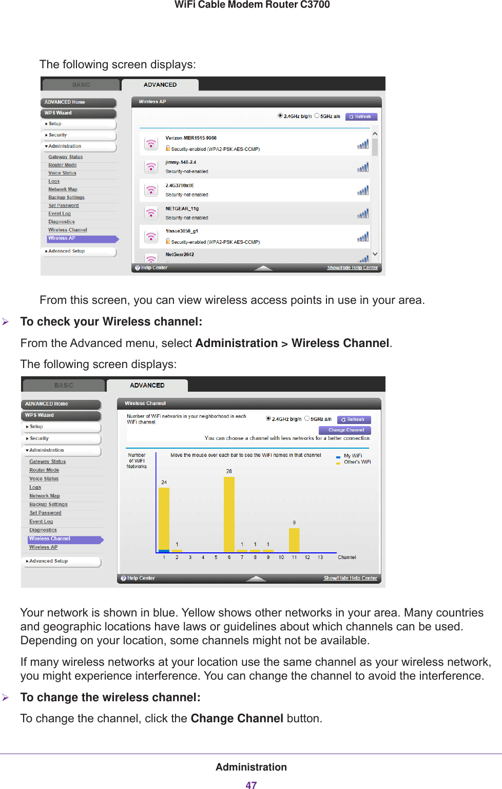
UserManual.wiki
>
Netgear orporated
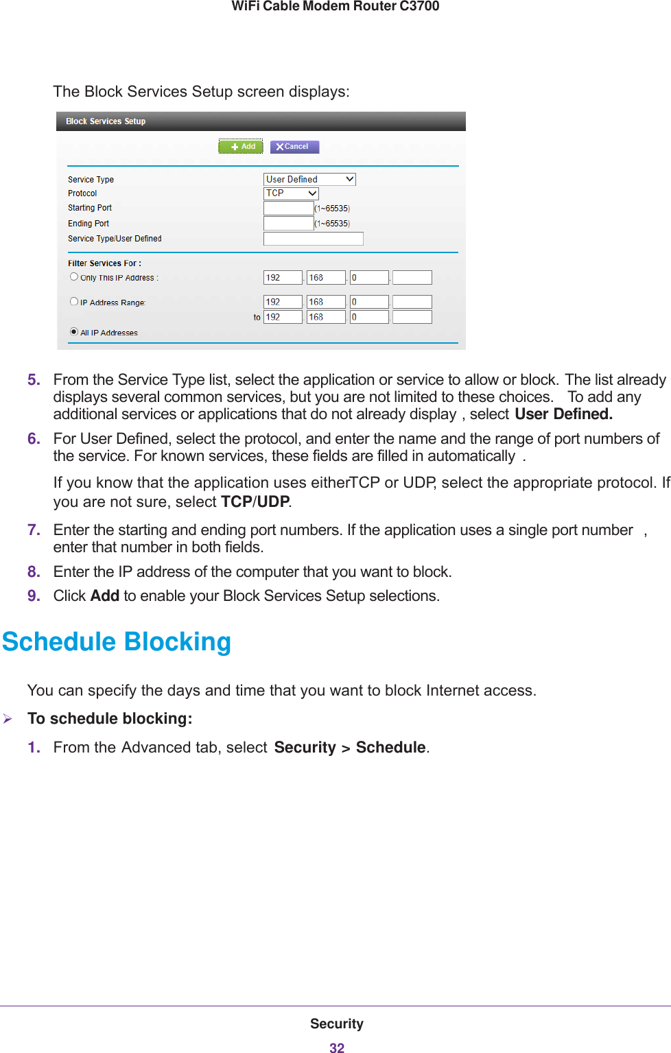
>
13300241 User Manual
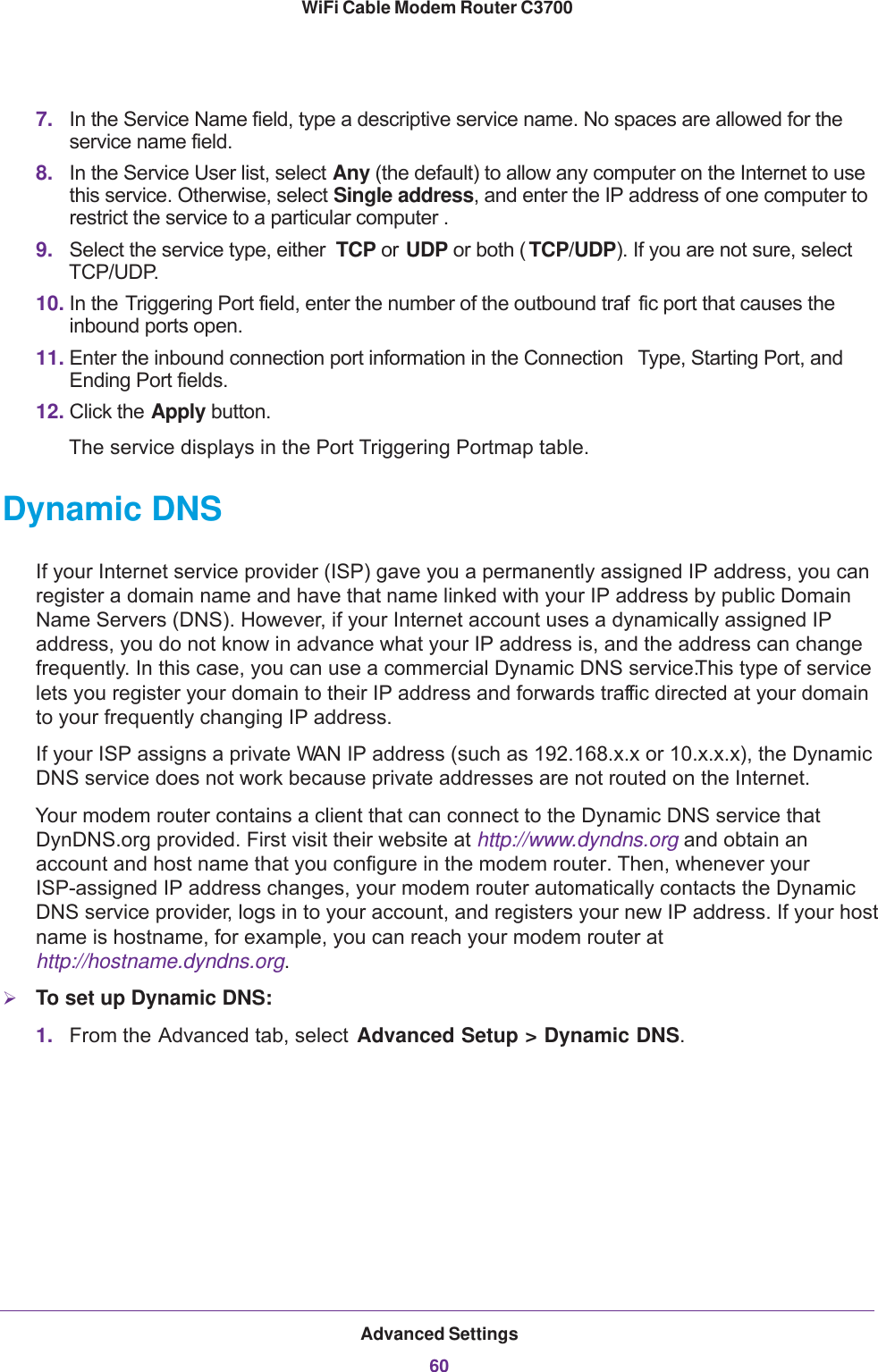
User Manual
Navigation menu
Upload a User Manual
Namespaces
Wiki Guide
HTML
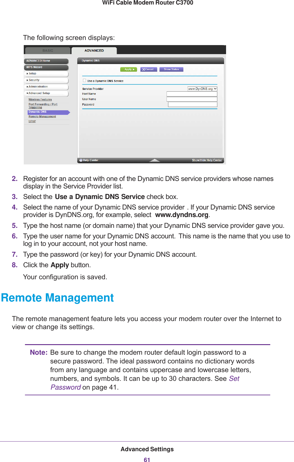
PDF
Info
Views
User Manual
Discussion / Help
Navigation