Netgear orporated 14200260 Wireless Cable Data Gateway User Manual rev
Netgear Incorporated Wireless Cable Data Gateway rev
UserManual.wiki
>
Netgear orporated
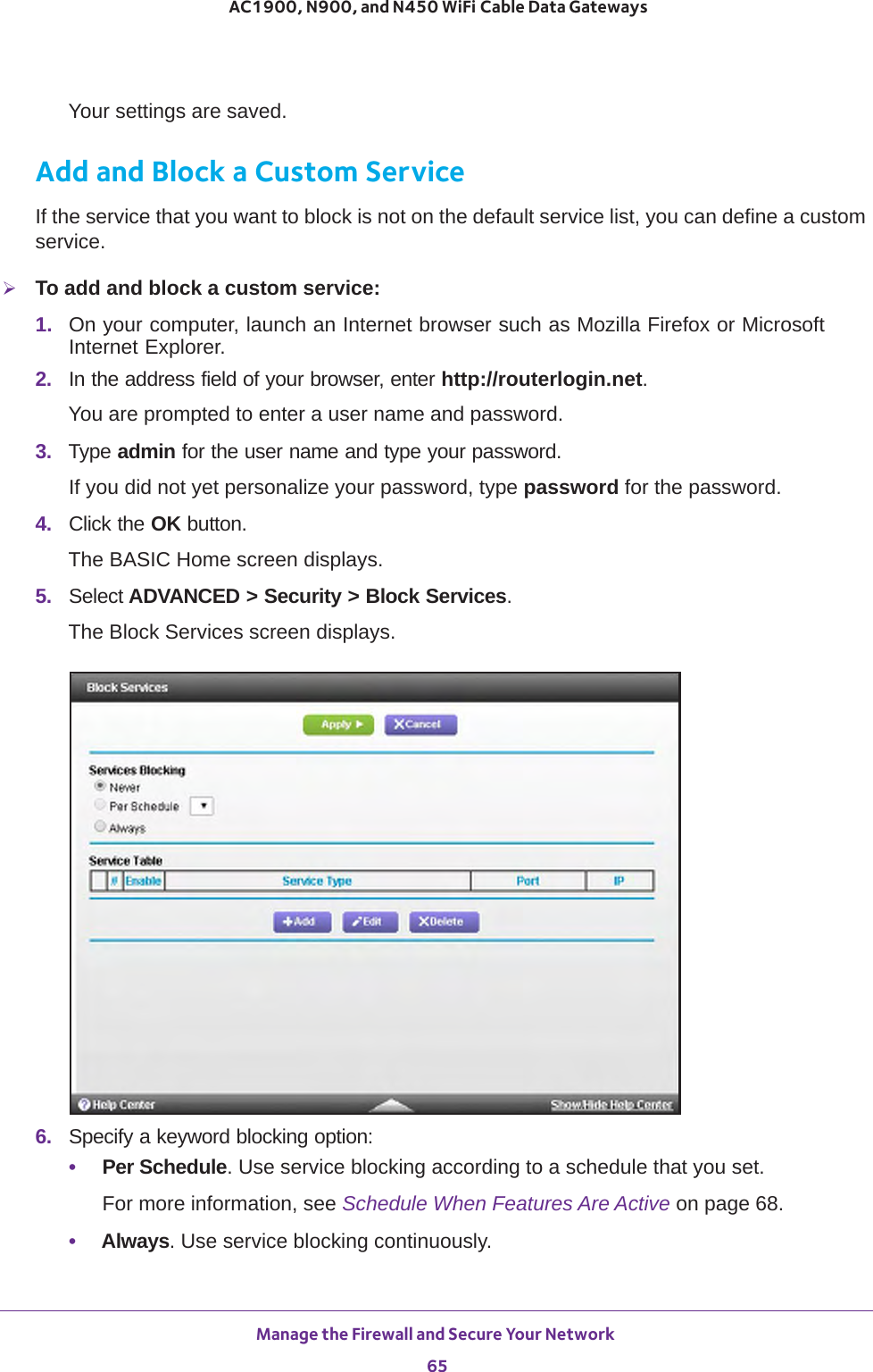
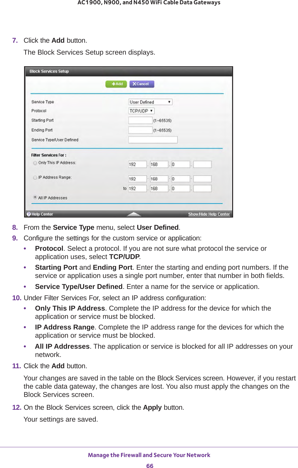
>
14200260 User Manual
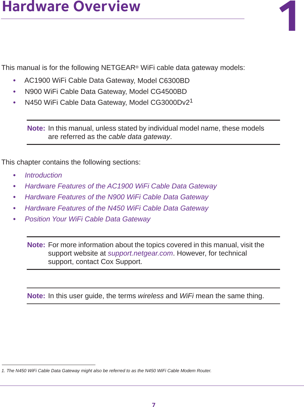
>
User Manual_rev.pdf
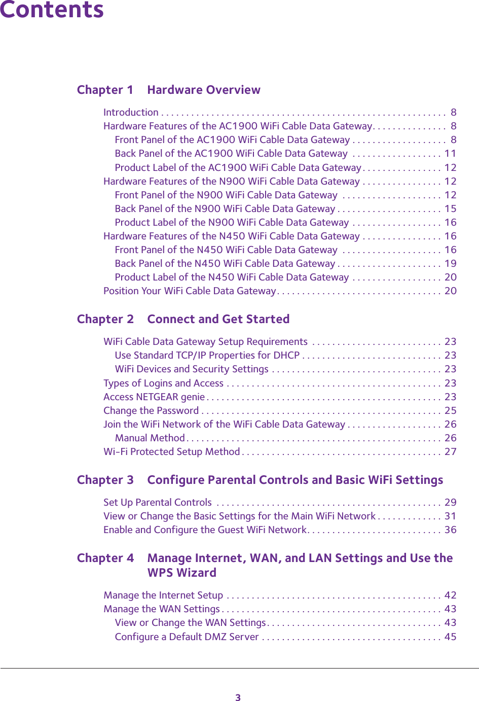
Contents
1.
User Manual (Statement)_rev 2.pdf
2.
User Manual_rev.pdf
User Manual_rev.pdf
Navigation menu
Upload a User Manual
Namespaces
Wiki Guide
HTML
PDF
Info
Views
User Manual
Discussion / Help
Navigation
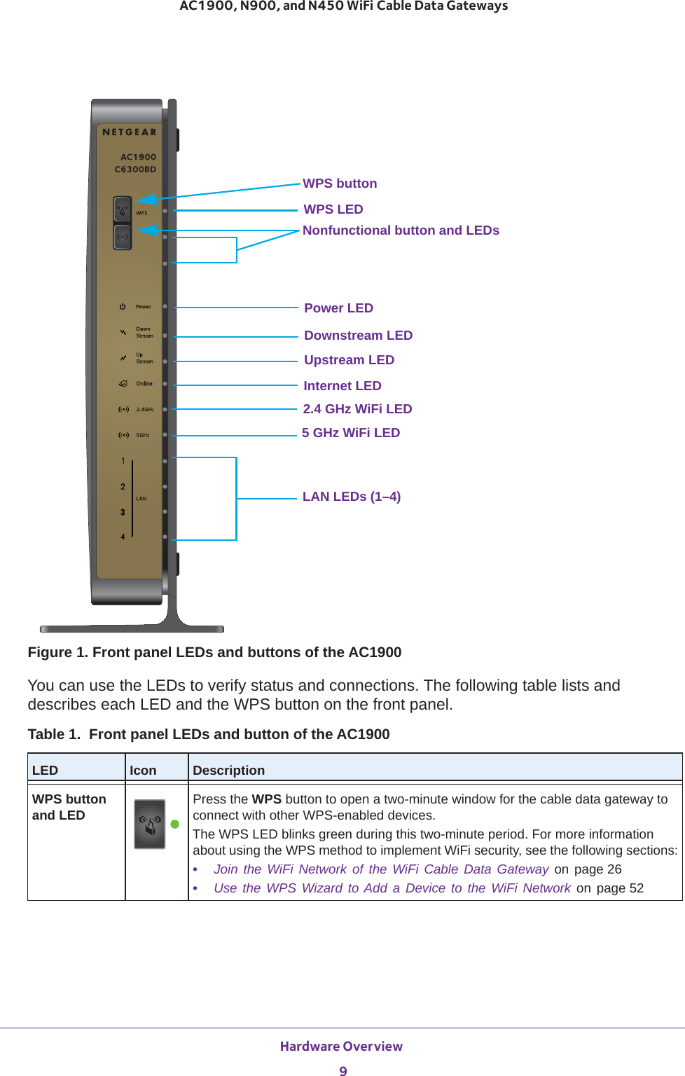
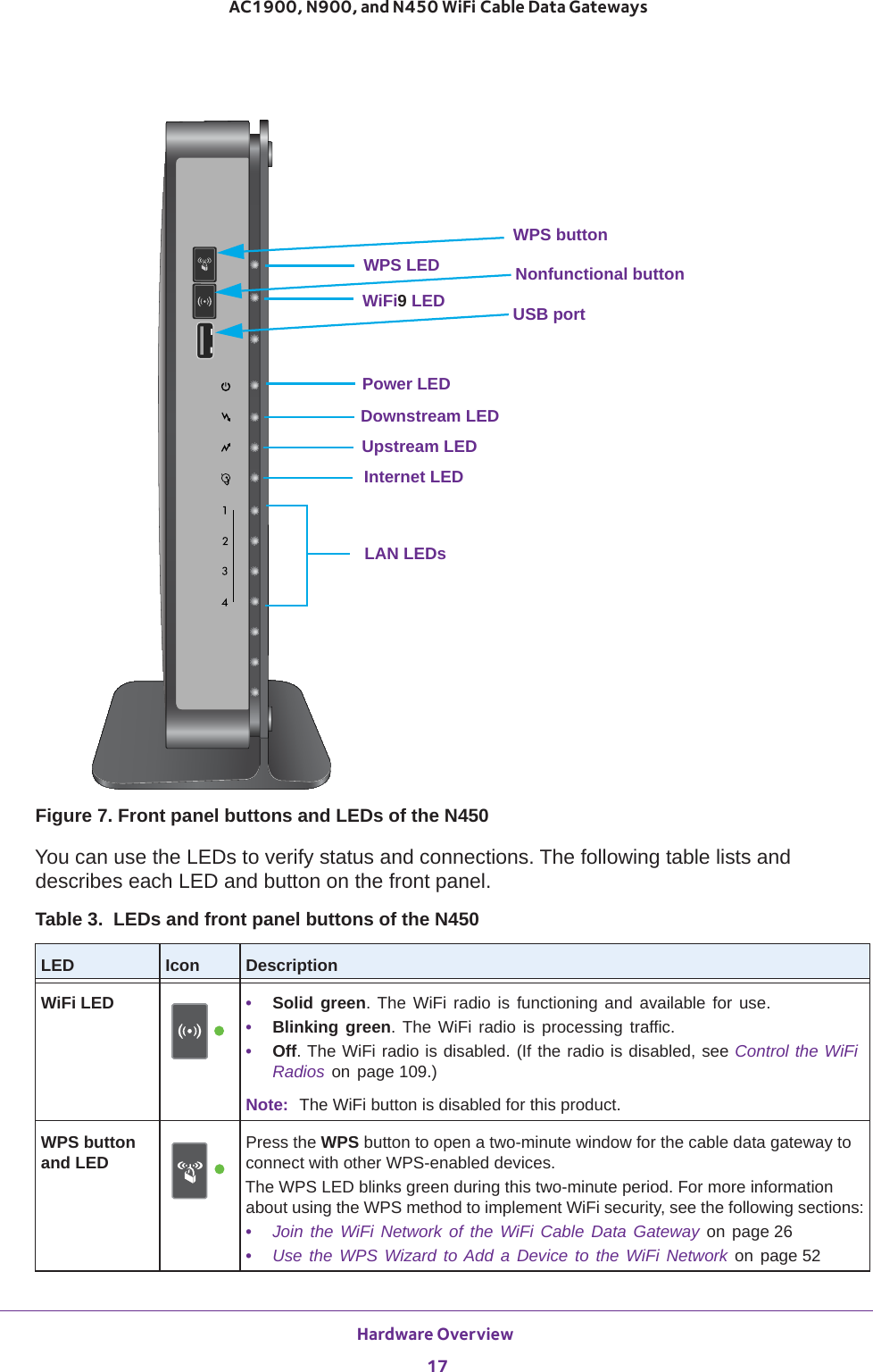
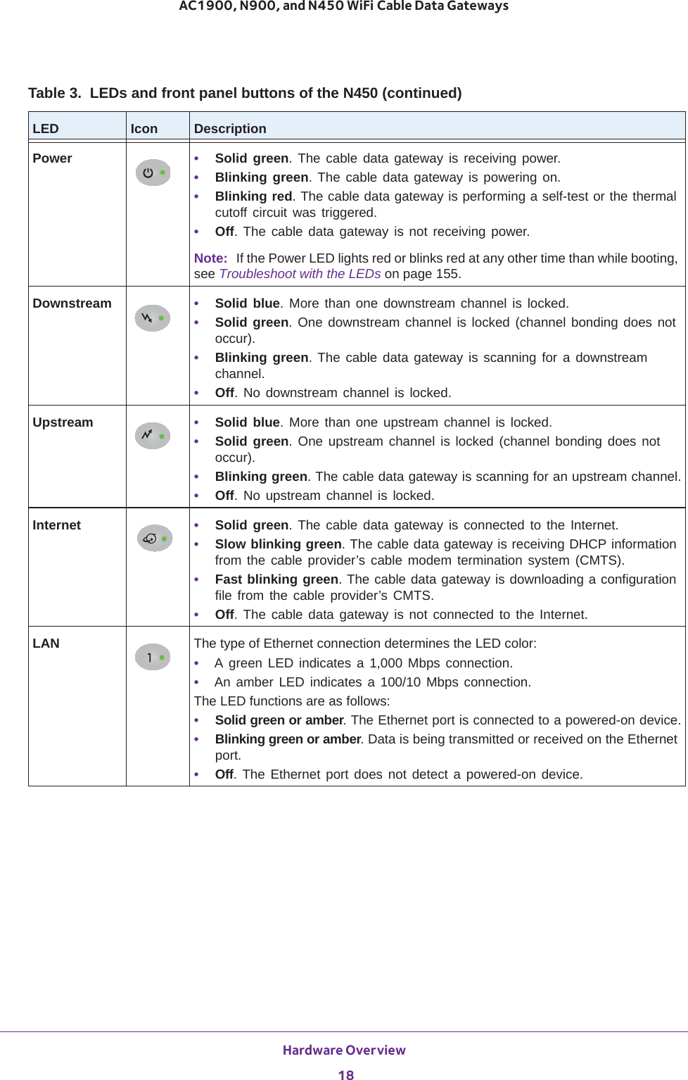
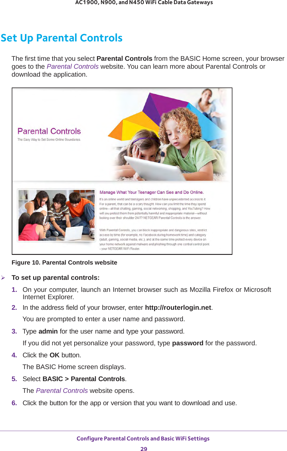
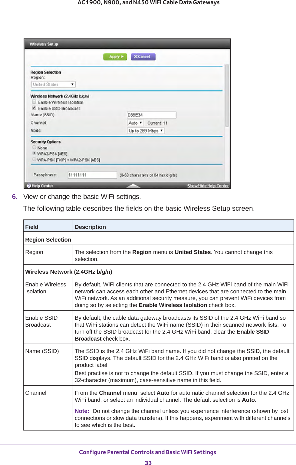
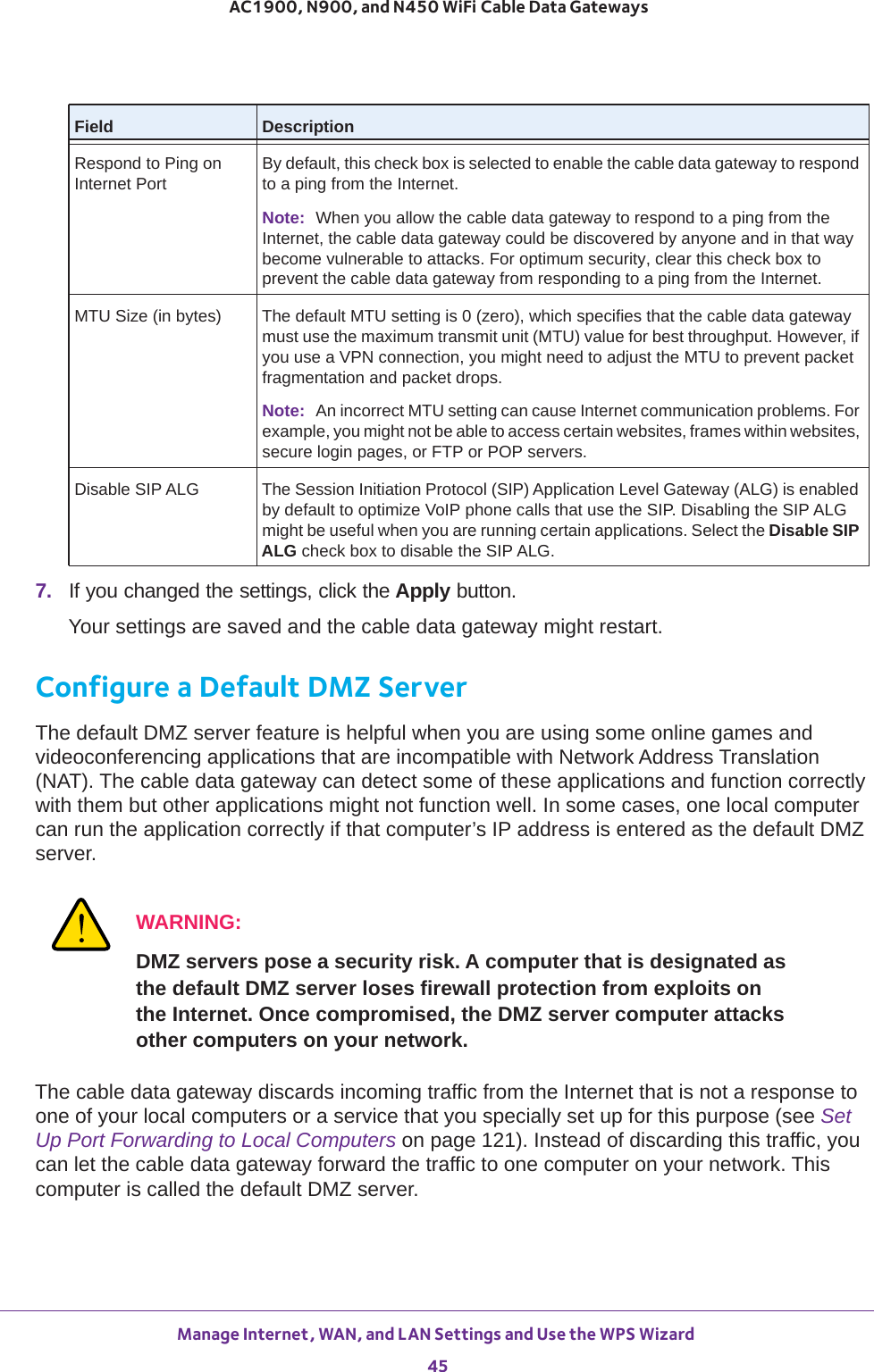
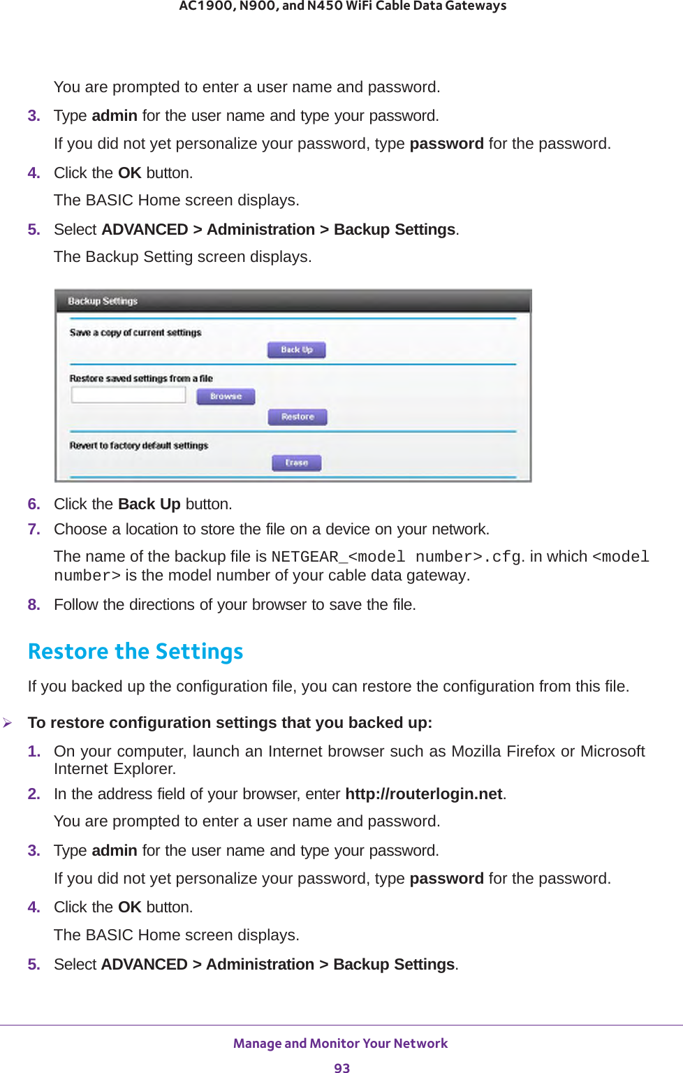
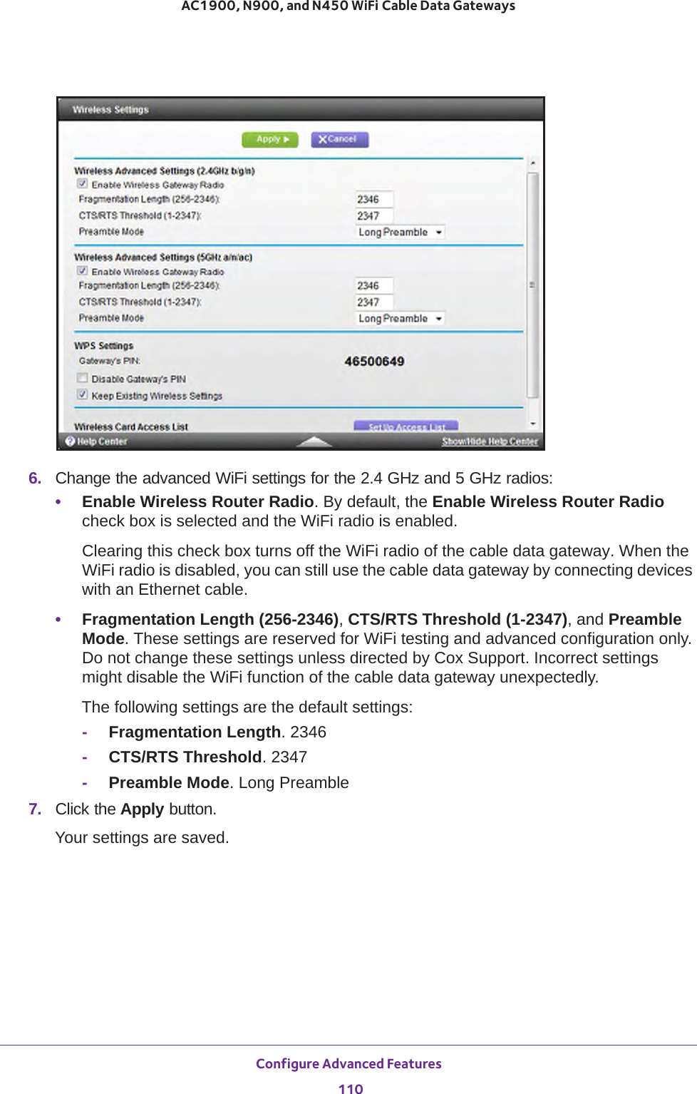
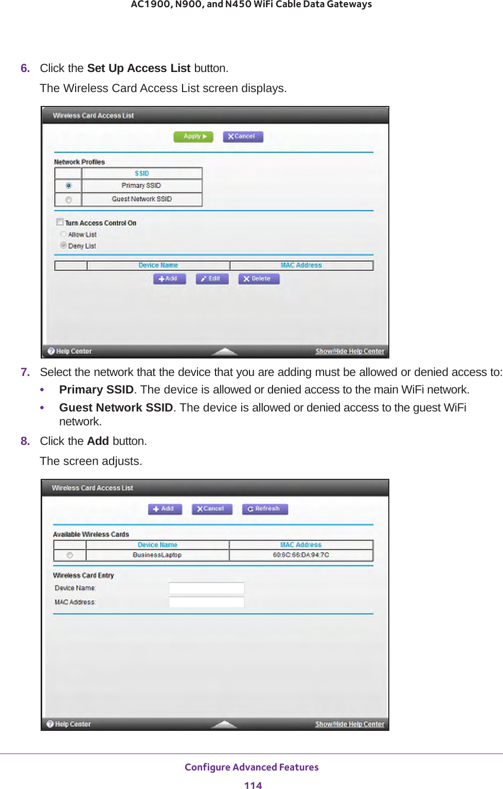
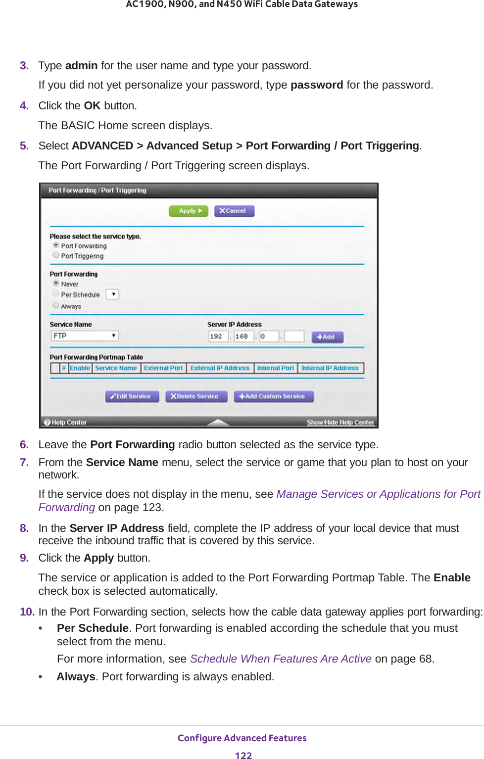
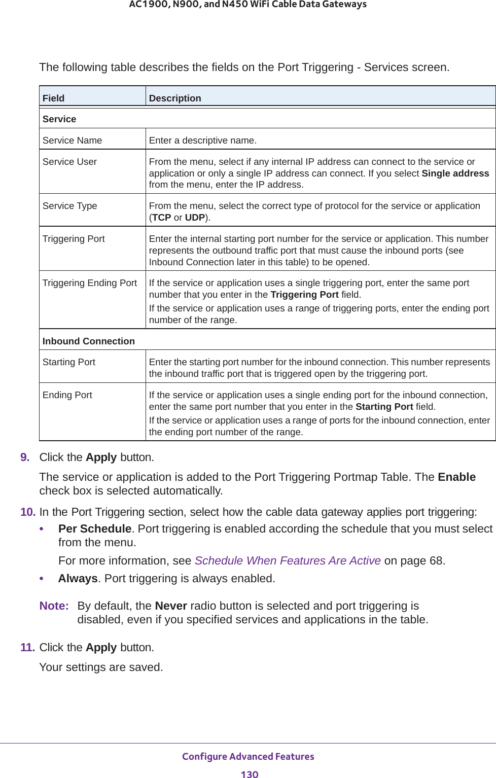
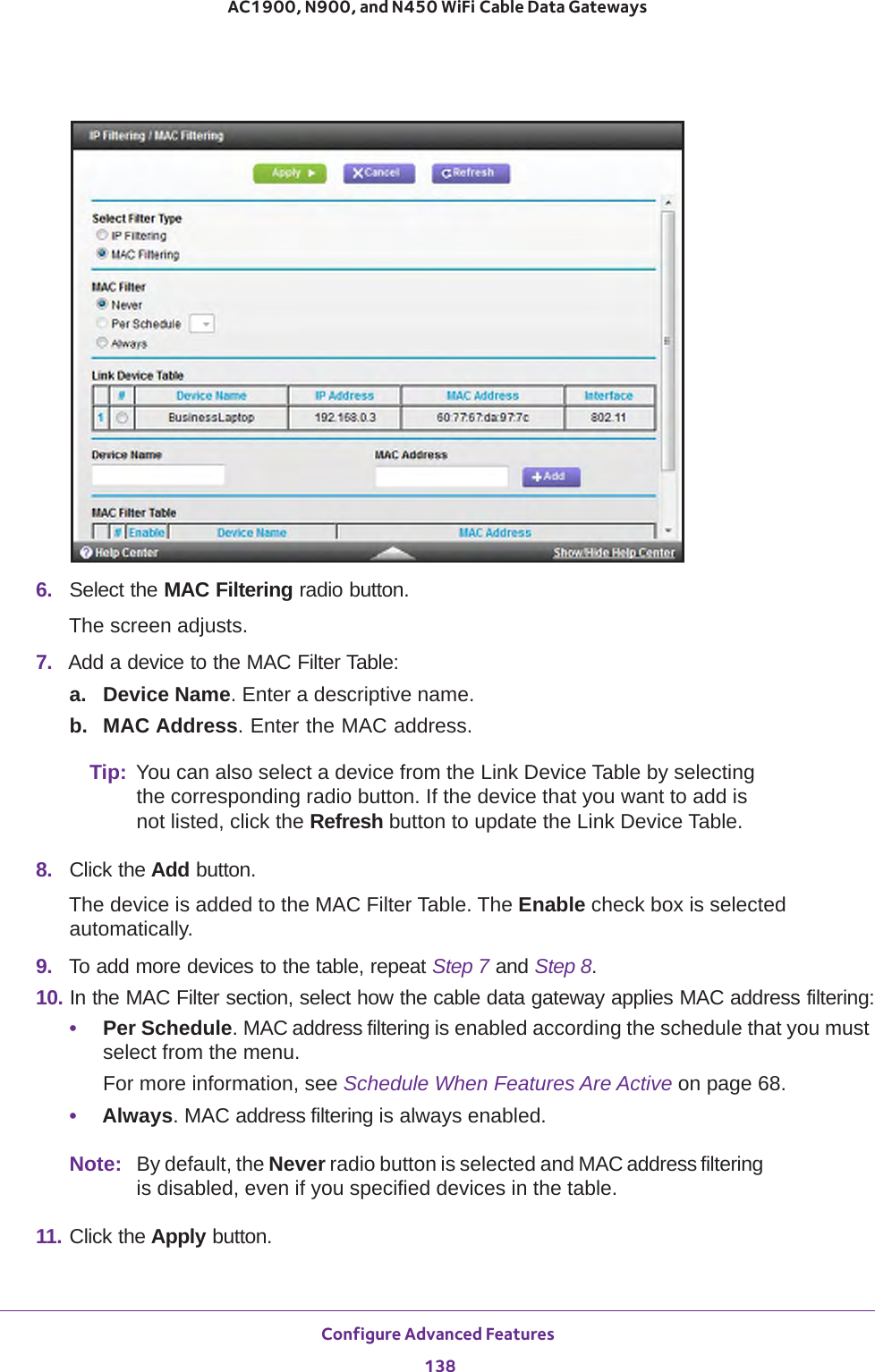
![Configure Parental Controls and Basic WiFi Settings 34AC1900, N900, and N450 WiFi Cable Data Gateways Mode From the Mode menu, select one of the following modes for the 2.4 GHz WiFi band:• Up to 54 Mbps. Legacy mode. This mode allows 802.11n, 802.11g, and 802.11b devices to join the network but limits 802.11n devices to function at up to 54 Mbps.• Up to 289 Mbps. Neighbor-friendly mode for reduced interference with neighboring WiFi networks. This mode allows 802.11n, 802.11g, and 802.11b devices to join the network but limits 802.11n devices to function at up to 289 Mbps. This mode is the default mode.The available performance mode (that is, the highest possible mode on the cable data gateway) depends on the model:• Models N900 and N450:Up to 450 Mbps. Performance mode. This mode allows 802.11n, 802.11g, and 802.11b devices to join the network and allows 802.11n devices to function at up to 450 Mbps.• Model AC1900:Up to 600 Mbps. Performance mode. This mode allows 802.11n, 802.11g, and 802.11b devices to join the network and allows 802.11n devices to function at up to 600 Mbps.Security OptionsNote: Best practise is not to change your preset security settings (WPA-PSK [TKIP] + WPA2-PASK [AES]).If you must change the WiFi security, select one of the following WiFi security options for the 2.4 GHz band of the main WiFi network:• None. An open WiFi network that does not provide any security. Any WiFi device can join the 2.4 GHz band of the main WiFi network. Because of complete lack of security, best practise is not to use an open main WiFi network.• WPA2-PSK [AES]. WPA2 provides a secure and fast connection but some older WiFi devices do not detect WPA2 and support only WPA. Select this mode to allow 802.11n devices to connect to the 2.4 GHz band of the main WiFi network at the fastest speed.To use this type of security, in the Passphrase field, enter a phrase of 8 to 63 characters. To join the 2.4 GHz band of the main WiFi network, a user must enter this passphrase.• WPA-PSK [TKIP] + WPA2-PASK [AES]. This type of security is the default setting and enables WiFi devices that support either WPA or WPA2 to join the cable data gateway’s WiFi network. If you did not change the passphrase, the default passphrase displays. The default passphrase is also printed on the product label.Best practise is not to change the default passphrase. If you must change the passphrase, in the Passphrase field, enter a phrase of 8 to 63 characters. To join the 2.4 GHz band of the main WiFi network, a user must enter this passphrase.Passphrase The passphrase that provides users access to the main WiFi network in the 2.4 GHZ band. The passphrase is also referred to as password or key.Field Description](https://usermanual.wiki/Netgear-orporated/14200260.User-Manual-rev-pdf/User-Guide-2441000-Page-34.png)
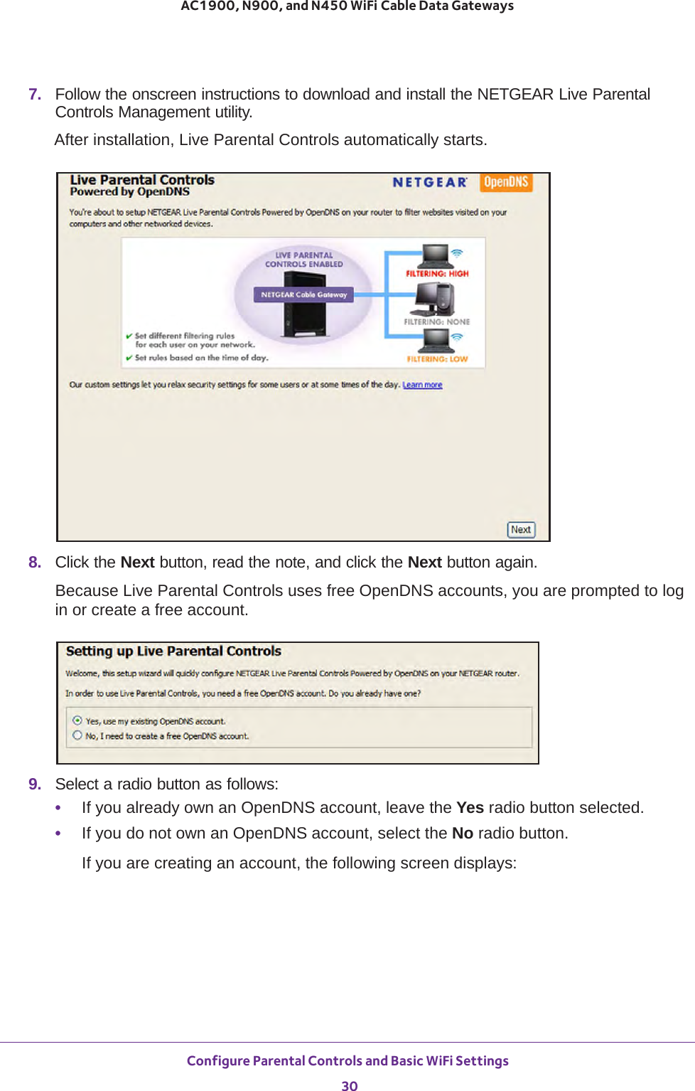
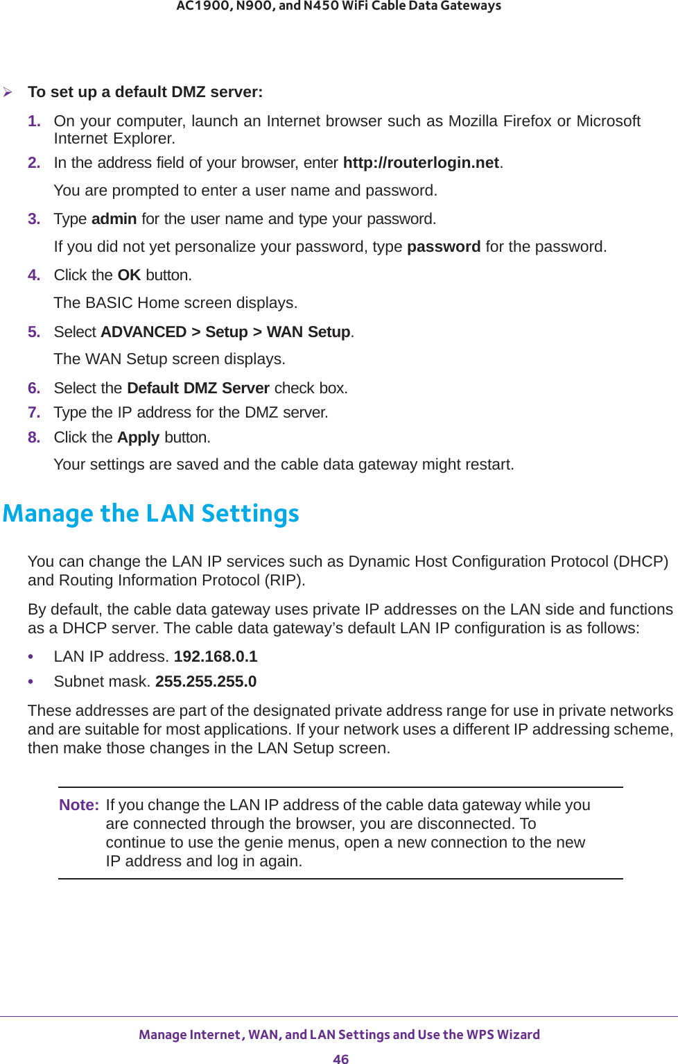
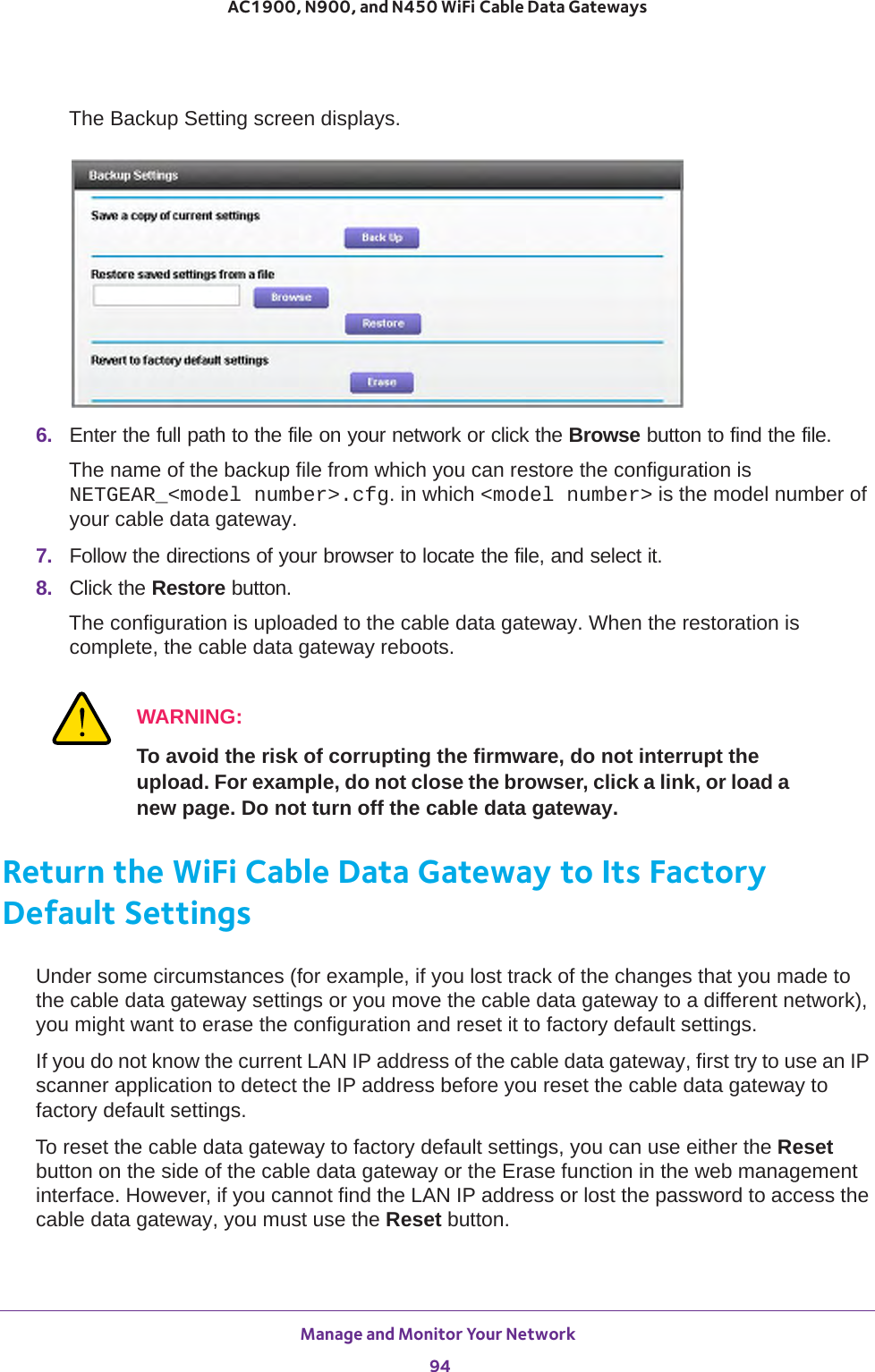
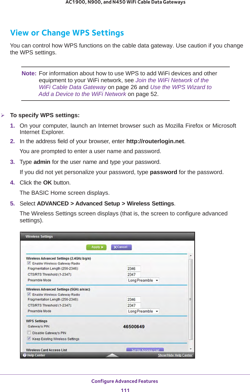
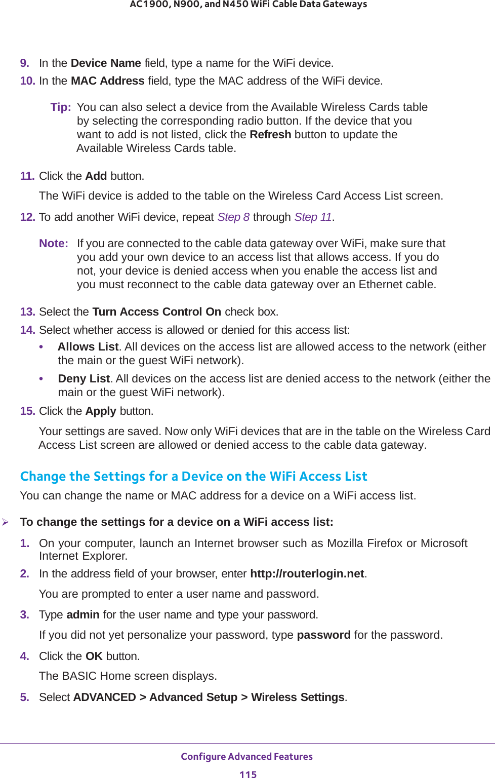
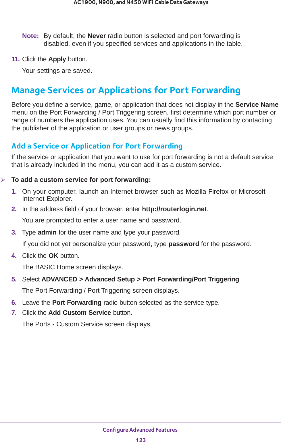
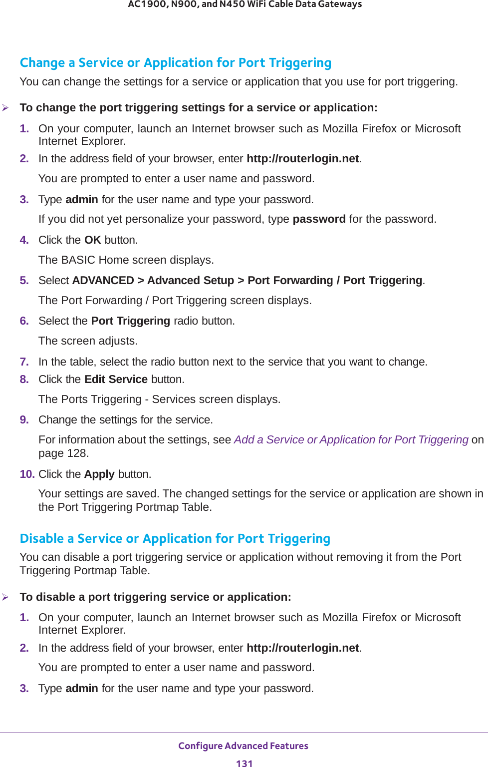
![Configure Parental Controls and Basic WiFi Settings 36AC1900, N900, and N450 WiFi Cable Data Gateways 7. If you changed the settings, click the Apply button.Your settings are saved.8. Set up and test your WiFi devices and computers to make sure that they can connect over WiFi.If they do not, check the following:•Is your WiFi device connected to your network or another WiFi network in your area? Some WiFi devices automatically connect to the first open network (without WiFi security) that they discover.•Does your WiFi device display in the network map? (See View the Network Map on page 87.) If it does, it is connected to the network.•Do you use the correct network name (SSID) and password? The default SSID and default password are on the product label.Enable and Configure the Guest WiFi NetworkBy default, the guest WiFi network is disabled. You can enable and configure the guest WiFi network.The WiFi mode of the guest WiFi network depends on the WiFi mode of the main WiFi network. For example, if you configure the WiFi mode for the main WiFi network as Up to 54 Mbps in the 2.4 GHz band, the guest WiFi network also functions in the Up to 54 Mbps Security OptionsNote: Best practise is not to change your preset security settings (WPA-PSK [TKIP] + WPA2-PASK [AES]).If you must change the WiFi security, select one of the following WiFi security options for the 5 GHz band of the main WiFi network:• None. An open WiFi network that does not provide any security. Any WiFi device can join the 5 GHz band of the main WiFi network. Because of complete lack of security, best practise is not to use an open main WiFi network.• WPA2-PSK [AES]. WPA2 provides a secure and fast connection but some older WiFi devices do not detect WPA2 and support only WPA. Select this mode to allow 802.11n devices to connect to the 5 GHz band of the main WiFi network at the fastest speed.To use this type of security, in the Passphrase field, enter a phrase of 8 to 63 characters. To join the 5 GHz band of the main WiFi network, a user must enter this passphrase.• WPA-PSK [TKIP] + WPA2-PASK [AES]. This type of security is the default setting and enables WiFi devices that support either WPA or WPA2 to join the 5 GHz band of the main WiFi network. If you did not change the passphrase, the default passphrase displays. The default passphrase is also printed on the product label.Best practise is not to change the default passphrase. If you must change the passphrase, in the Passphrase field, enter a phrase of 8 to 63 characters. To join the 5 GHz band of the main WiFi network, a user must enter this passphrase.Passphrase The passphrase that provides users access to the main WiFi network in the 5 GHZ band. The passphrase is also referred to as password or key.Field Description](https://usermanual.wiki/Netgear-orporated/14200260.User-Manual-rev-pdf/User-Guide-2441000-Page-36.png)
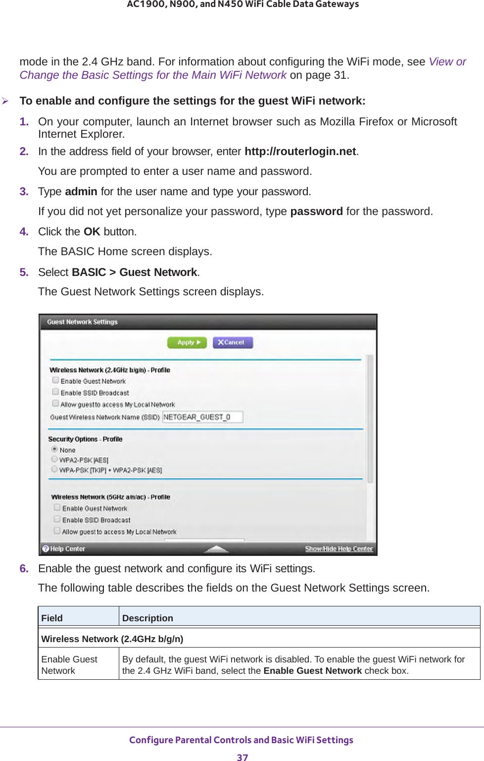
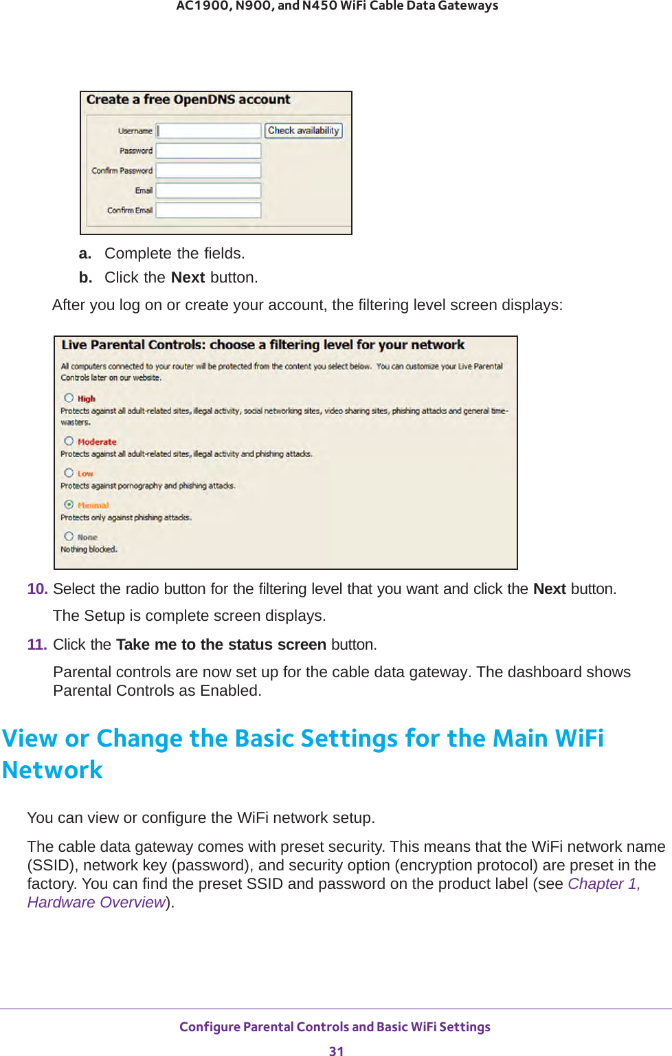
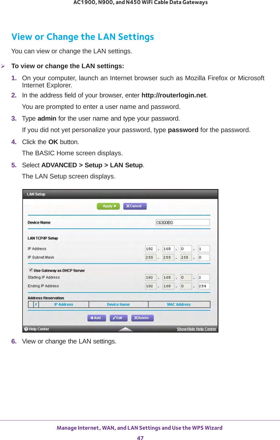
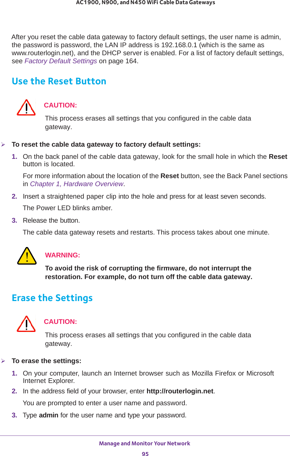
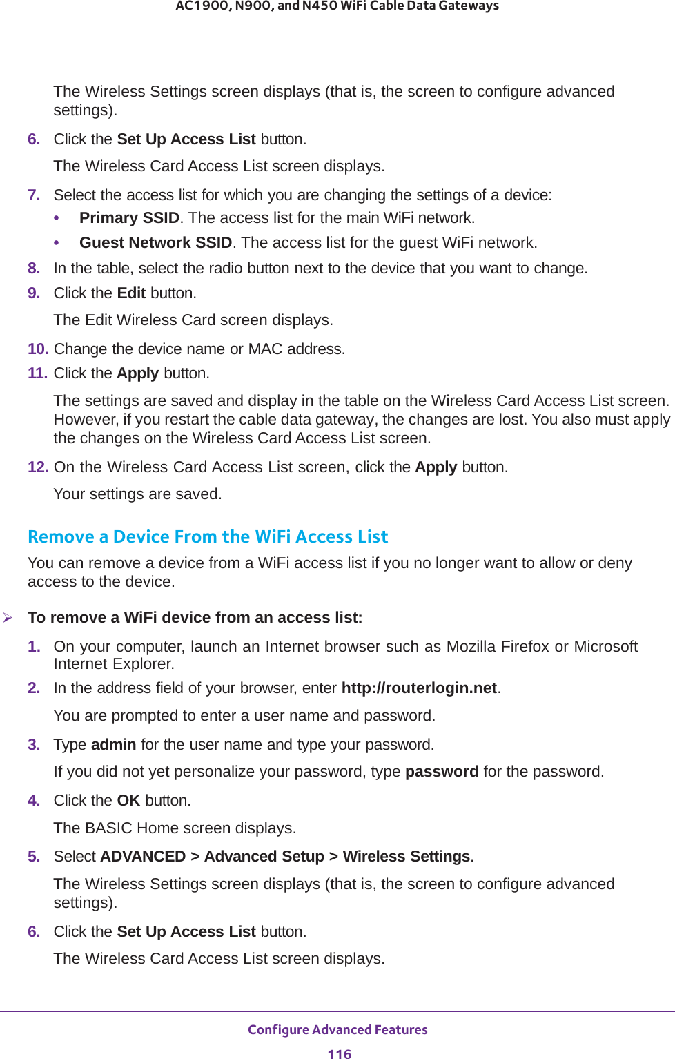
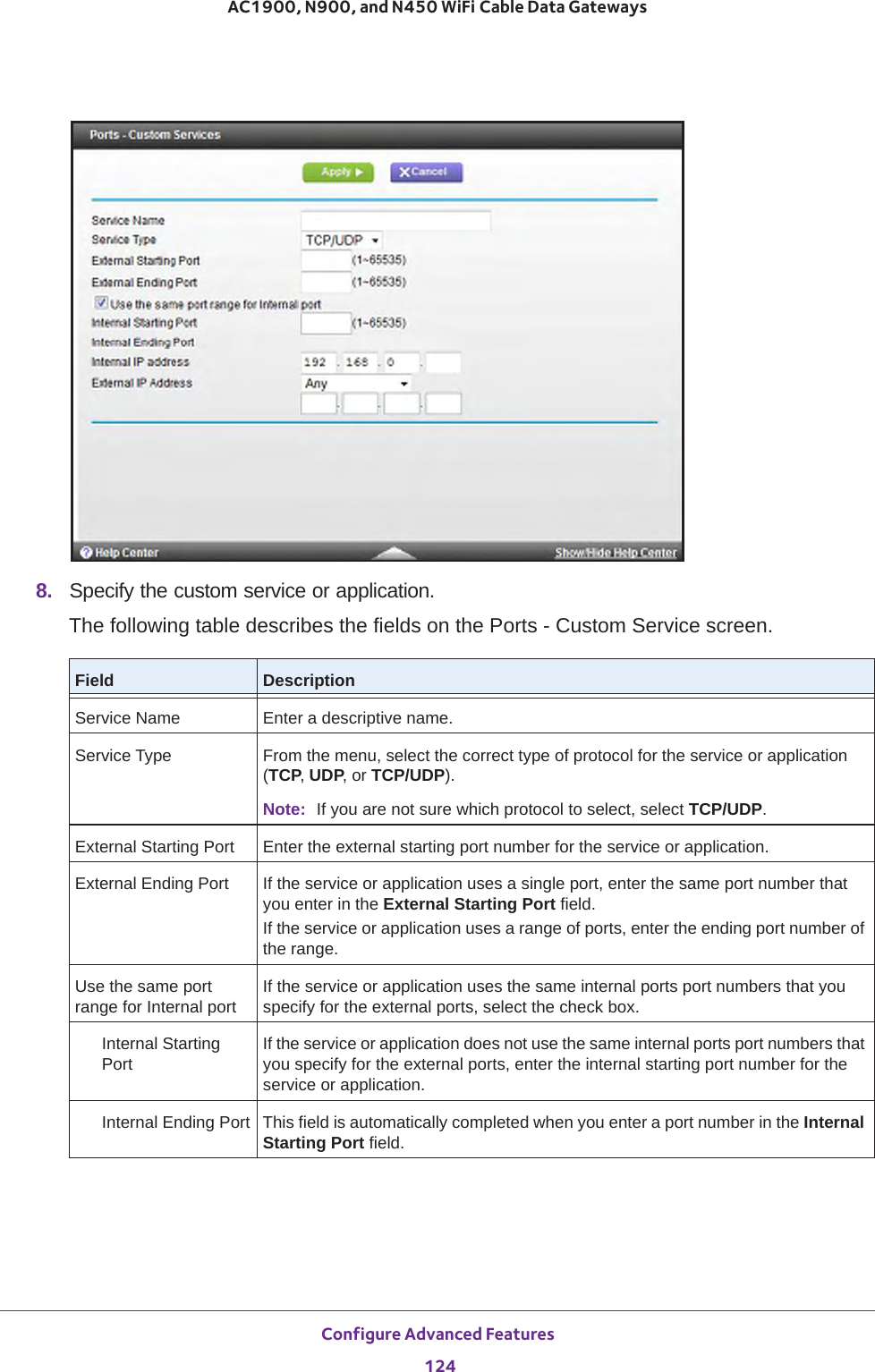
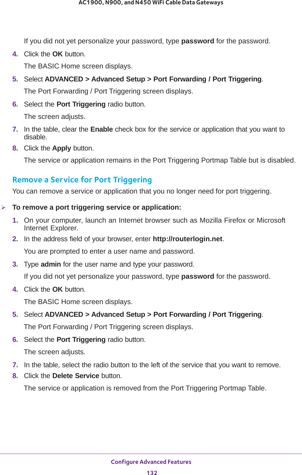
![Configure Parental Controls and Basic WiFi Settings 38AC1900, N900, and N450 WiFi Cable Data Gateways Enable SSID Broadcast By default, the cable data gateway broadcasts its SSID of the 2.4 GHz WiFi band so WiFi stations can detect the WiFi name (SSID) in their scanned network lists. To turn off the SSID broadcast for the 2.4 GHz WiFi band for the guest WiFi network, clear the Enable SSID Broadcast check box.Allow guest to access My Local NetworkBy default, WiFi clients that are connected to the 2.4 GHz WiFi band of guest WiFi network cannot access WiFi devices and Ethernet devices that are connected to the main WiFi network. To allow access to the main WiFi network, select the Allow guest to access My Local Network check box.Guest Wireless Network Name (SSID) The SSID is the 2.4 GHz WiFi band name. If you did not change the SSID, the default SSID displays, which is NETGEAR_GUEST_0. (This name is same as the default SSID for the 5 GHz band of the guest WiFi network.)If you want to change the SSID in the 2.4 GHz WiFi band for the guest WiFi network, enter a 32-character (maximum), case-sensitive name in this field.Security Options ProfileIf you want to change the WiFi security, select one of the following WiFi security options for the 2.4 GHz band of the guest WiFi network:• None. An open WiFi network that does not provide any security. Any WiFi device can join the 2.4 GHz band of the guest WiFi network. This is the default setting for the guest WiFi network.• WPA2-PSK [AES]. WPA2 provides a secure and fast connection but some older WiFi devices do not detect WPA2 and support only WPA. Select this mode to allow 802.11n devices to connect to the 2.4 GHz band of the guest WiFi network at the fastest speed. To use this type of security, in the Passphrase field, enter a phrase of 8 to 63 characters. To join the 2.4 GHz band of the guest WiFi network, a user must enter this passphrase.• WPA-PSK [TKIP] + WPA2-PASK [AES]. This type of security is the default setting and enables WiFi devices that support either WPA or WPA2 to join the 2.4 GHz band of the guest WiFi network.To use this type of security, in the Passphrase field, enter a phrase of 8 to 63 characters. To join the 2.4 GHz band of the guest WiFi network, a user must enter this passphrase.Security OptionsPassphrase The passphrase that provides users access to the guest WiFi network in the 2.4 GHZ band. The passphrase is also referred to as password or key.Field Description](https://usermanual.wiki/Netgear-orporated/14200260.User-Manual-rev-pdf/User-Guide-2441000-Page-38.png)
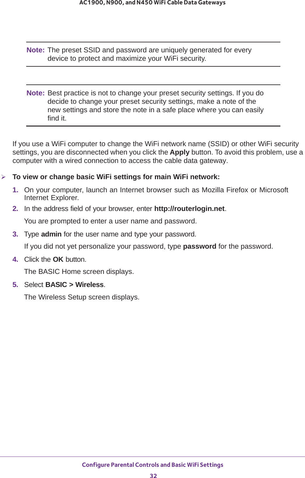
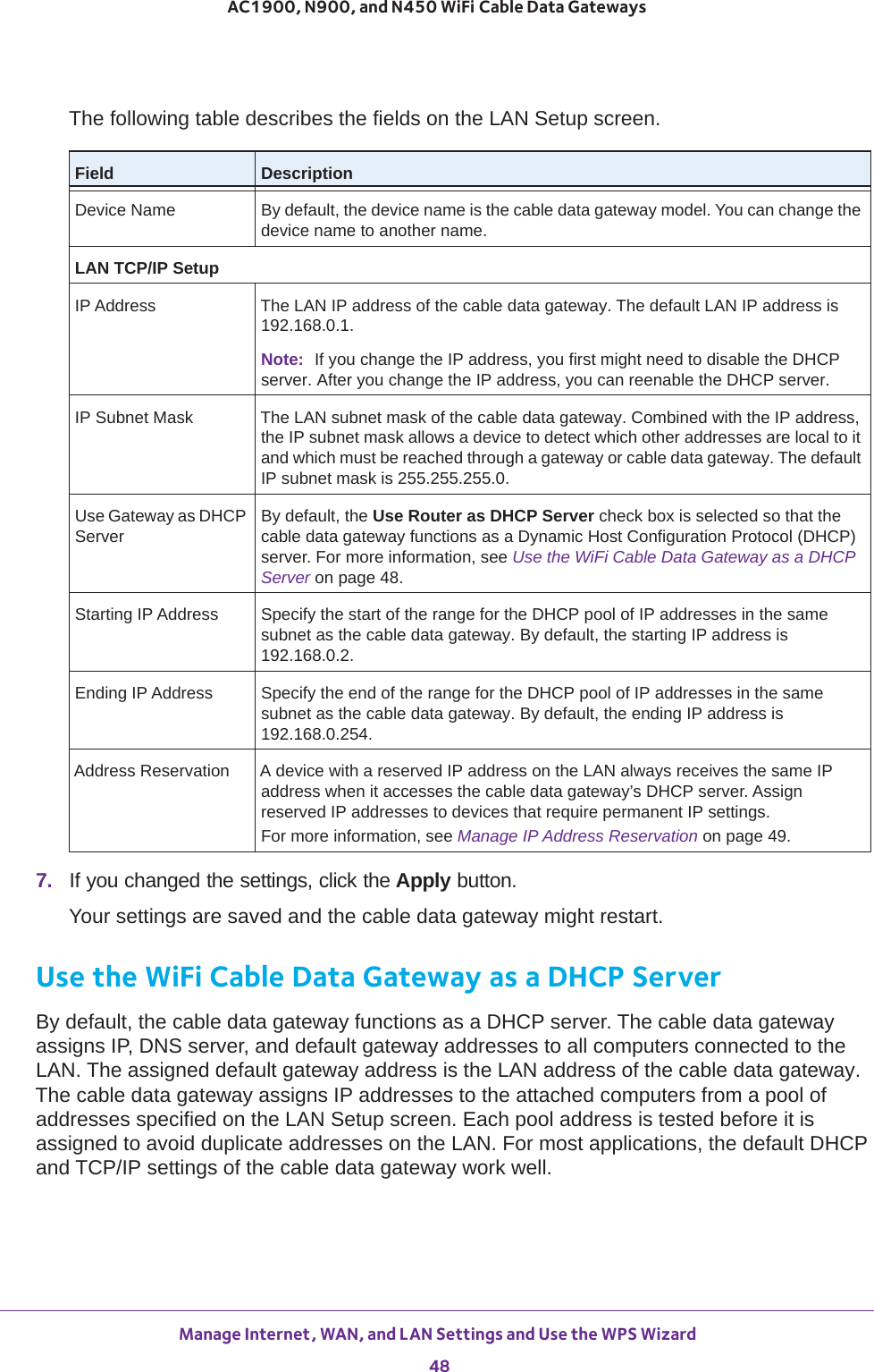
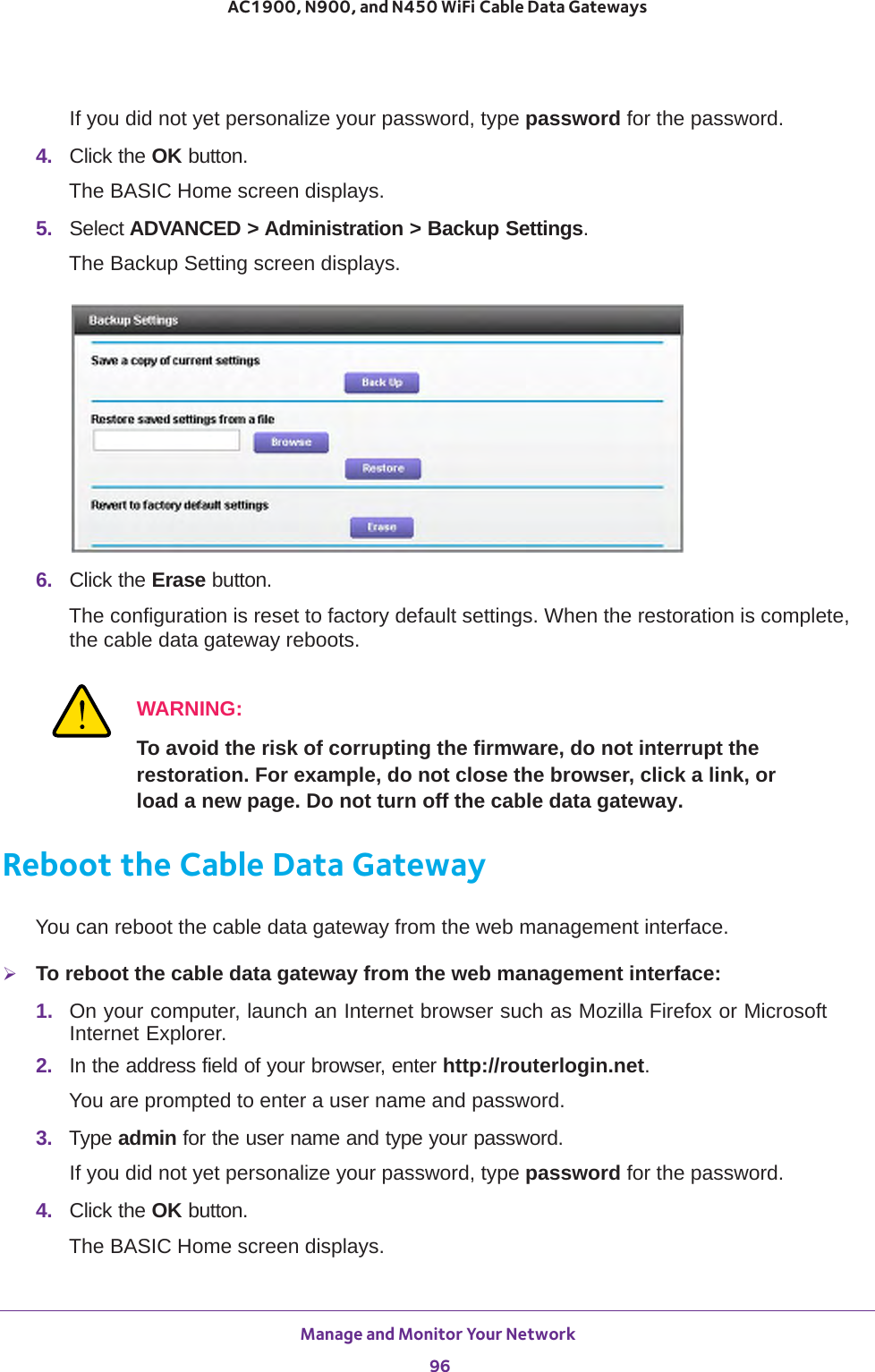
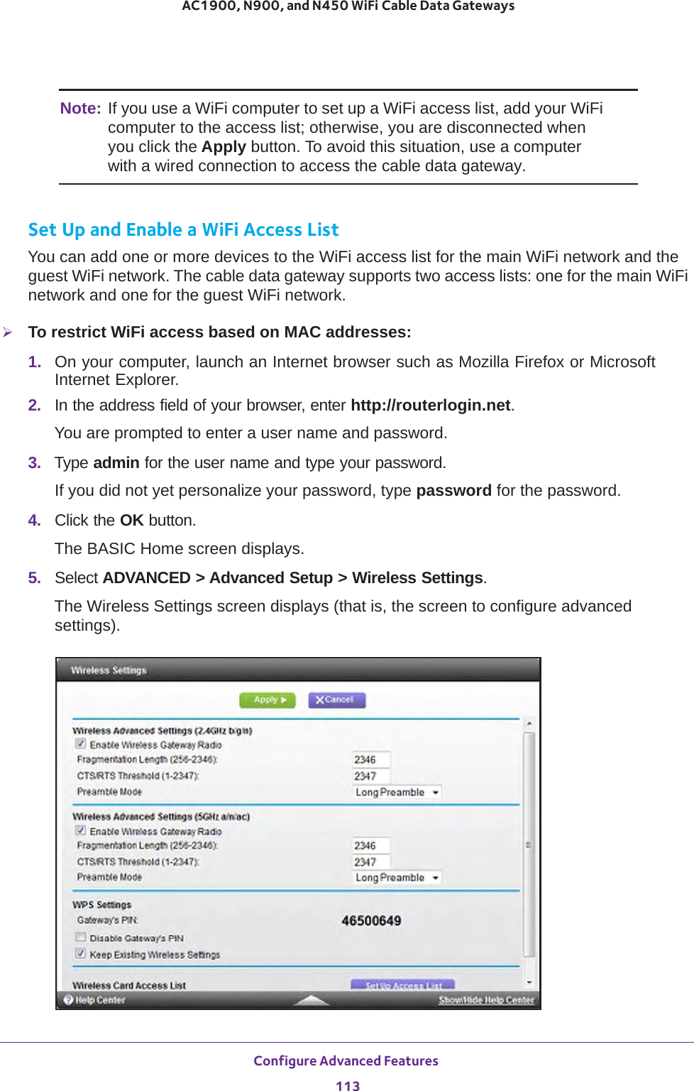
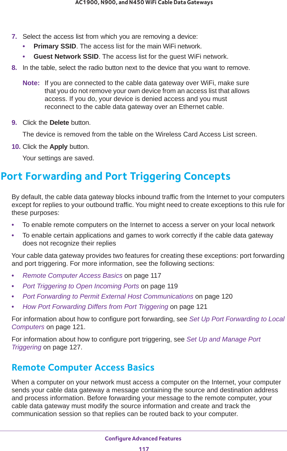
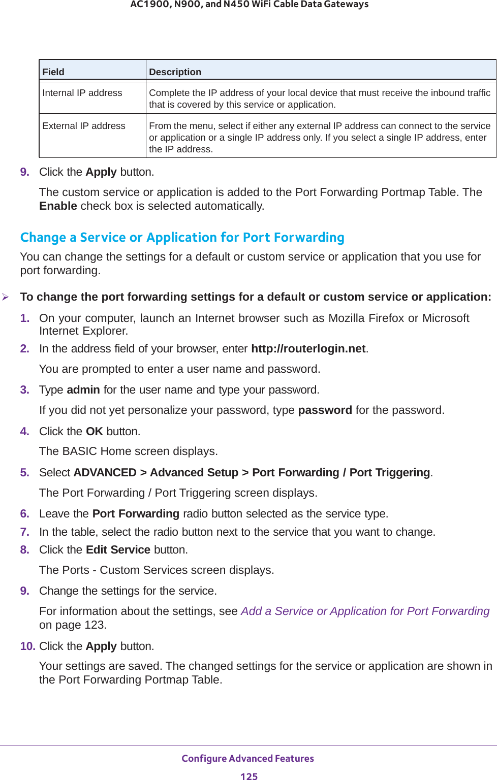
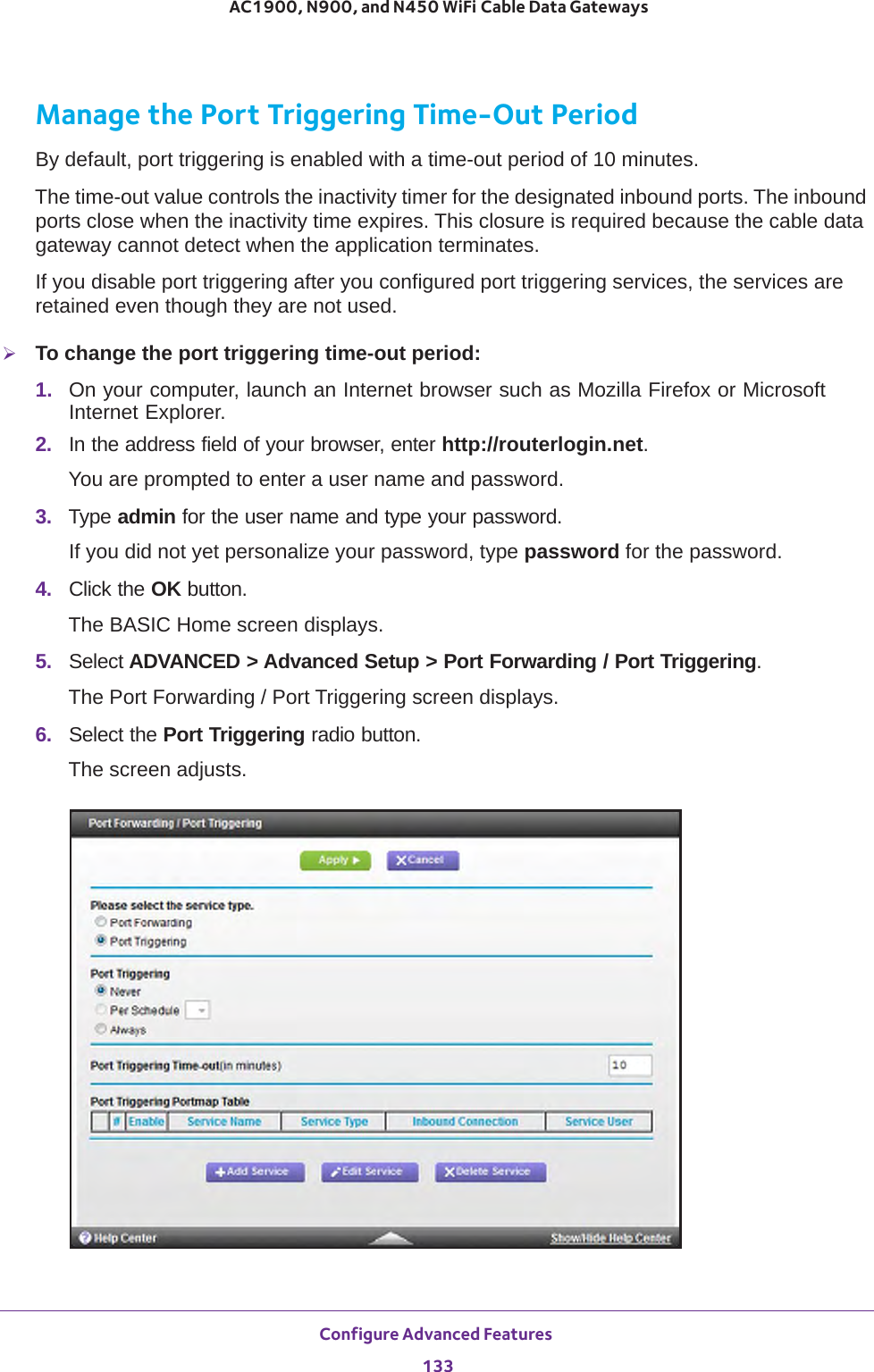
![Configure Parental Controls and Basic WiFi Settings 39 AC1900, N900, and N450 WiFi Cable Data Gateways7. If you changed the settings, click the Apply button.Your settings are saved.8. Set up and test your WiFi devices and computers to make sure that they can connect over WiFi.If they do not, check the following:•Is your WiFi device connected to your network or another WiFi network in your area? Some WiFi devices automatically connect to the first open network (without WiFi security) that they discover.•Does your WiFi device display in the network map? (See View the Network Map on page 87.) If it does, it is connected to the network.Wireless Network (5GHz a/n/ac)Enable Guest NetworkBy default, the guest WiFi network is disabled. To enable the guest WiFi network for the 5 GHz WiFi band, select the Enable Guest Network check box.Enable SSID Broadcast By default, the cable data gateway broadcasts its SSID of the 5 GHz WiFi band so WiFi stations can detect the WiFi name (SSID) in their scanned network lists. To turn off the SSID broadcast for the 5 GHz WiFi band for the guest WiFi network, clear the Enable SSID Broadcast check box.Allow guest to access My Local NetworkBy default, WiFi clients that are connected to the 5 GHz WiFi band of guest WiFi network cannot access WiFi devices and Ethernet devices that are connected to the main WiFi network. To allow access to the main WiFi network, select the Allow guest to access My Local Network check box.Guest Wireless Network Name (SSID) The SSID is the 5 GHz WiFi band name. If you did not change the SSID, the default SSID displays, which is NETGEAR_GUEST_0. (This name is same as the default SSID for the 2.4 GHz band of the guest WiFi network.)If you want to change the SSID in the 5 GHz WiFi band for the guest WiFi network, enter a 32-character (maximum), case-sensitive name in this field.If you want to change the WiFi security, select one of the following WiFi security options for the 5 GHz band of the guest WiFi network:• None. An open WiFi network that does not provide any security. Any WiFi device can join the 5 GHz band of the guest WiFi network. This is the default setting for the guest WiFi network.• WPA2-PSK [AES]. WPA2 provides a secure and fast connection but some older WiFi devices do not detect WPA2 and support only WPA. Select this mode to allow 802.11n devices to connect to the 5 GHz band of the guest WiFi network at the fastest speed. To use this type of security, in the Passphrase field, enter a phrase of 8 to 63 characters. To join the 5 GHz band of the guest WiFi network, a user must enter this passphrase.• WPA-PSK [TKIP] + WPA2-PASK [AES]. This type of security is the default setting and enables WiFi devices that support either WPA or WPA2 to join the cable data gateway’s WiFi network.To use this type of security, in the Passphrase field, enter a phrase of 8 to 63 characters. To join the 5 GHz band of the guest WiFi network, a user must enter this passphrase.Security OptionsPassphrase The passphrase that provides users access to the guest WiFi network in the 5 GHZ band. The passphrase is also referred to as password or key.Field Description](https://usermanual.wiki/Netgear-orporated/14200260.User-Manual-rev-pdf/User-Guide-2441000-Page-39.png)
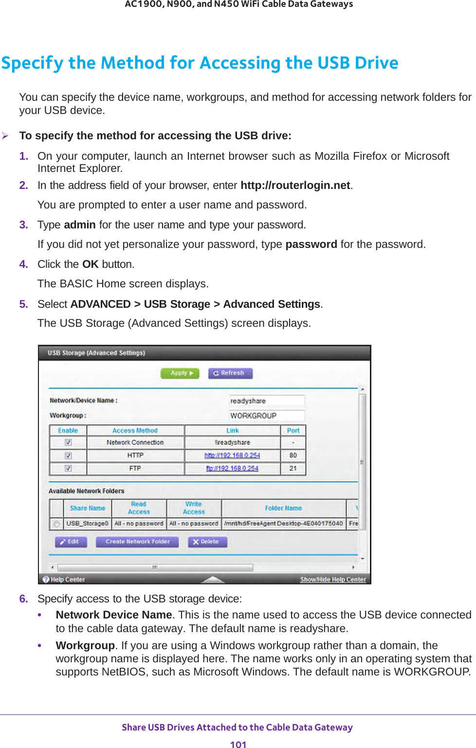
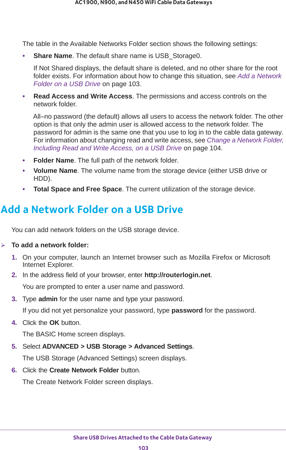
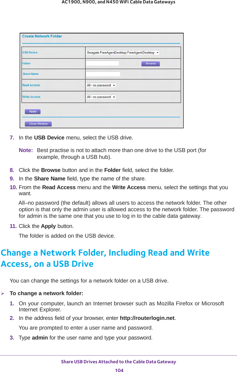
![Share USB Drives Attached to the Cable Data Gateway 102AC1900, N900, and N450 WiFi Cable Data Gateways •Access Method. By default USB access to the network, HTTP, and FTP are enabled. (File Transfer Protocol [FTP] lets you send and receive large files fast.) You can disable access by clearing the Enable check boxes to the left of the Network Neighborhood, HTTP, and FTP entries in the table.7. If you changed the settings, click the Apply button.Your changes are saved.View Network Folders on a USB DriveYou can view the network folders on the USB storage device.To view network folders:1. On your computer, launch an Internet browser such as Mozilla Firefox or Microsoft Internet Explorer. 2. In the address field of your browser, enter http://routerlogin.net.You are prompted to enter a user name and password.3. Type admin for the user name and type your password.If you did not yet personalize your password, type password for the password.4. Click the OK button. The BASIC Home screen displays.5. Select ReadyShare.The USB Storage (Basic Settings) screen displays.](https://usermanual.wiki/Netgear-orporated/14200260.User-Manual-rev-pdf/User-Guide-2441000-Page-102.png)
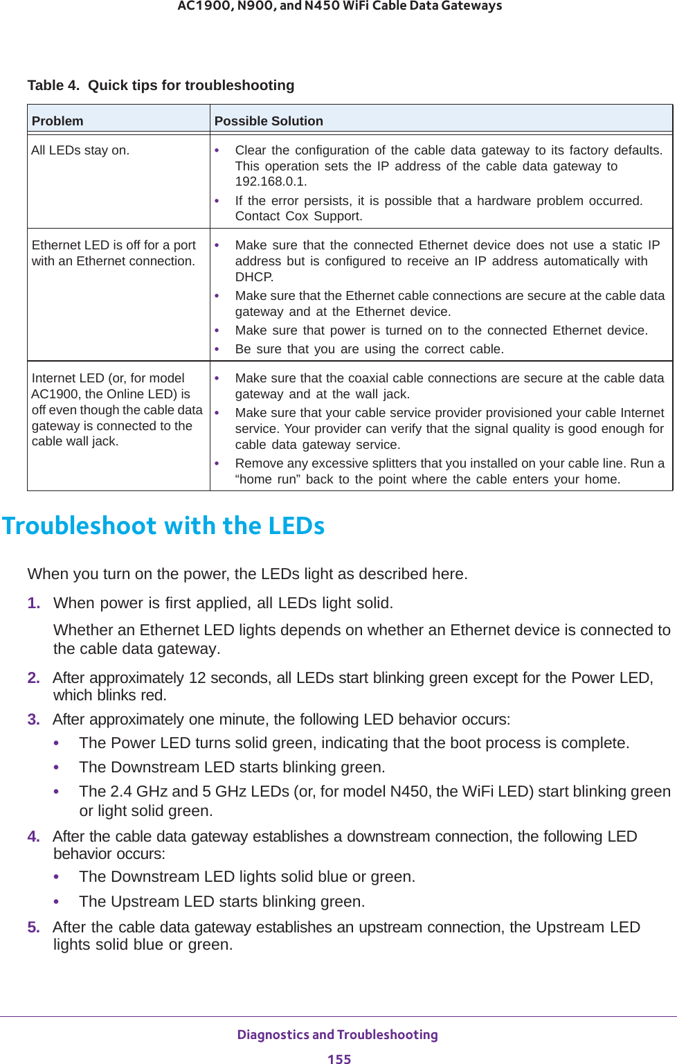
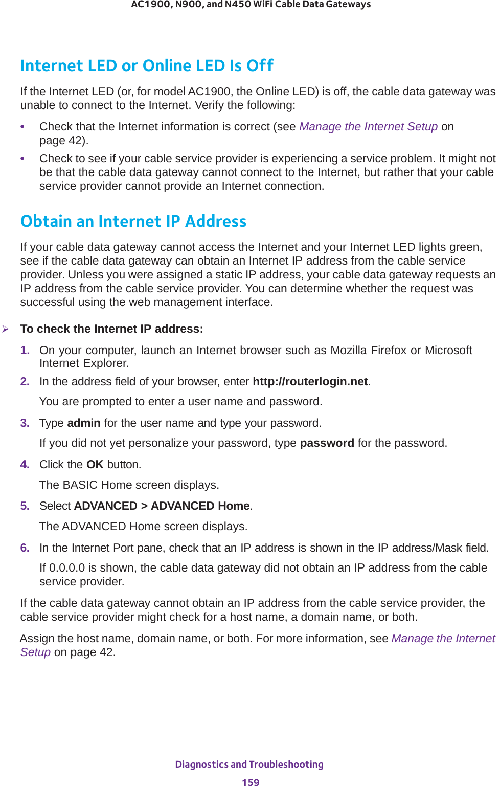
![Diagnostics and Troubleshooting 154AC1900, N900, and N450 WiFi Cable Data Gateways Quick Tips for TroubleshootingThe following table includes tips for troubleshooting some common problems. Table 4. Quick tips for troubleshootingProblem Possible SolutionYour WiFi network is unresponsive or does not function normally.Restart your WiFi network:1. Turn off and unplug the cable data gateway.2. Plug in the cable data gateway and turn it on. Wait two minutes.You cannot connect over WiFi to the cable data gateway.• Make sure that the WiFi settings in your WiFi device and cable data gateway match exactly.For a device that is connected over WiFi, the WiFi network name (SSID) and WiFi security settings of the cable data gateway and WiFi computer must match exactly. The default SSID and password are on the cable data gateway product label (see Chapter 1, Hardware Overview).• Make sure that your WiFi device supports the security that you are using for your WiFi network (WPA2-PSK [AES] or WPA-PSK [TKIP] + WPA2-PASK [AES]). For information about WiFi security settings, see View or Change the Basic Settings for the Main WiFi Network on page 31.• Make sure that the cable data gateway is not too far from your WiFi device or too close.- Move your WiFi device near the cable data gateway but at least 6 feet (about 2 meters) away and see if the signal strength improves.- Make sure that the WiFi signal is not blocked by objects between the cable data gateway and your WiFi device.• Make sure that the 2.4 GHz LED or 5 GHz LED (or, for model N450, the WiFi LED) on the cable data gateway is not off.If this LED is off, the WiFi radio might be disabled. For more information about the WiFi radio, see Control the WiFi Radios on page 109.• Make sure that the cable data gateway’s SSID broadcast is not disabled.If the cable data gateway’s SSID broadcast is disabled, the WiFi network name is hidden and does not display in your WiFi device’s scanning list. To connect to a hidden network, you must type the network name and the WiFi password. For more information about the SSID broadcast, see View or Change the Basic Settings for the Main WiFi Network on page 31.• If you set up an access list on the advanced Wireless Settings screen (see Set Up a WiFi Access List by MAC Address on page 112), add the MAC address of each WiFi device to the cable data gateway’s access list.• Make sure that your WiFi device is not configured with a static IP address but is configured to receive an IP address automatically with DHCP.All LEDs are off when the cable data gateway is plugged in.Make sure that the power cord is properly connected to your cable data gateway and that the power supply adapter is properly connected to a functioning power outlet. Check that you are using the power adapter that came in the product package and not any other power adapter.If the error persists, a hardware problem occurred. Contact Cox Support.](https://usermanual.wiki/Netgear-orporated/14200260.User-Manual-rev-pdf/User-Guide-2441000-Page-154.png)
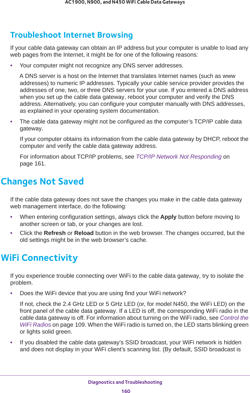
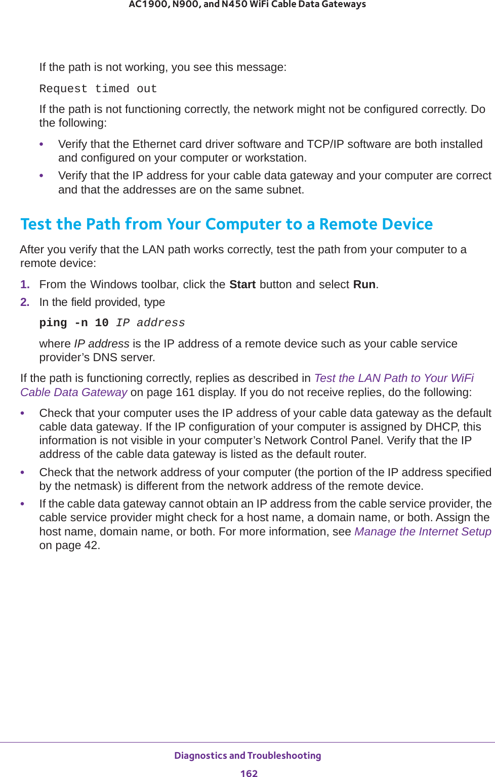
![Diagnostics and Troubleshooting 161 AC1900, N900, and N450 WiFi Cable Data Gatewaysenabled.) For more information, see View or Change the Basic Settings for the Main WiFi Network on page 31.•Does your WiFi device support the security that you are using for your WiFi network (WPA2-PSK [AES] or WPA-PSK [TKIP] + WPA2-PASK [AES])? For information about changing the WiFi security, see View or Change the Basic Settings for the Main WiFi Network on page 31.Note: If you want to change the WiFi settings for the cable data gateway, use an Ethernet cable to connect a computer to a LAN port on the cable data gateway and then log in to the cable data gateway.If your WiFi device finds your network but the signal strength is weak, check these conditions:•Is your cable data gateway too far from your WiFi device or too close? Place your WiFi device near the cable data gateway but at least 6 feet (about 2 meters) away and see whether the signal strength improves.•Are objects between the cable data gateway and your WiFi device blocking the WiFi signal?TCP/IP Network Not RespondingMost TCP/IP terminal devices and routers provide a ping utility for sending an echo request packet to the designated device. The device responds with an echo reply to tell whether a TCP/IP network is responding to requests.Test the LAN Path to Your WiFi Cable Data GatewayYou can ping the cable data gateway from your computer to verify that the LAN path to your cable data gateway is set up correctly.To ping the cable data gateway from a Windows computer:1. From the Windows taskbar, click the Start button and select Run.2. In the field provided, type ping followed by the IP address of the cable data gateway, as in this example:ping 192.168.0.13. Click the OK button.A message such as the following one displays:Pinging <IP address> with 32 bytes of dataIf the path is working, you see this message:Reply from < IP address >: bytes=32 time=NN ms TTL=xxx](https://usermanual.wiki/Netgear-orporated/14200260.User-Manual-rev-pdf/User-Guide-2441000-Page-161.png)
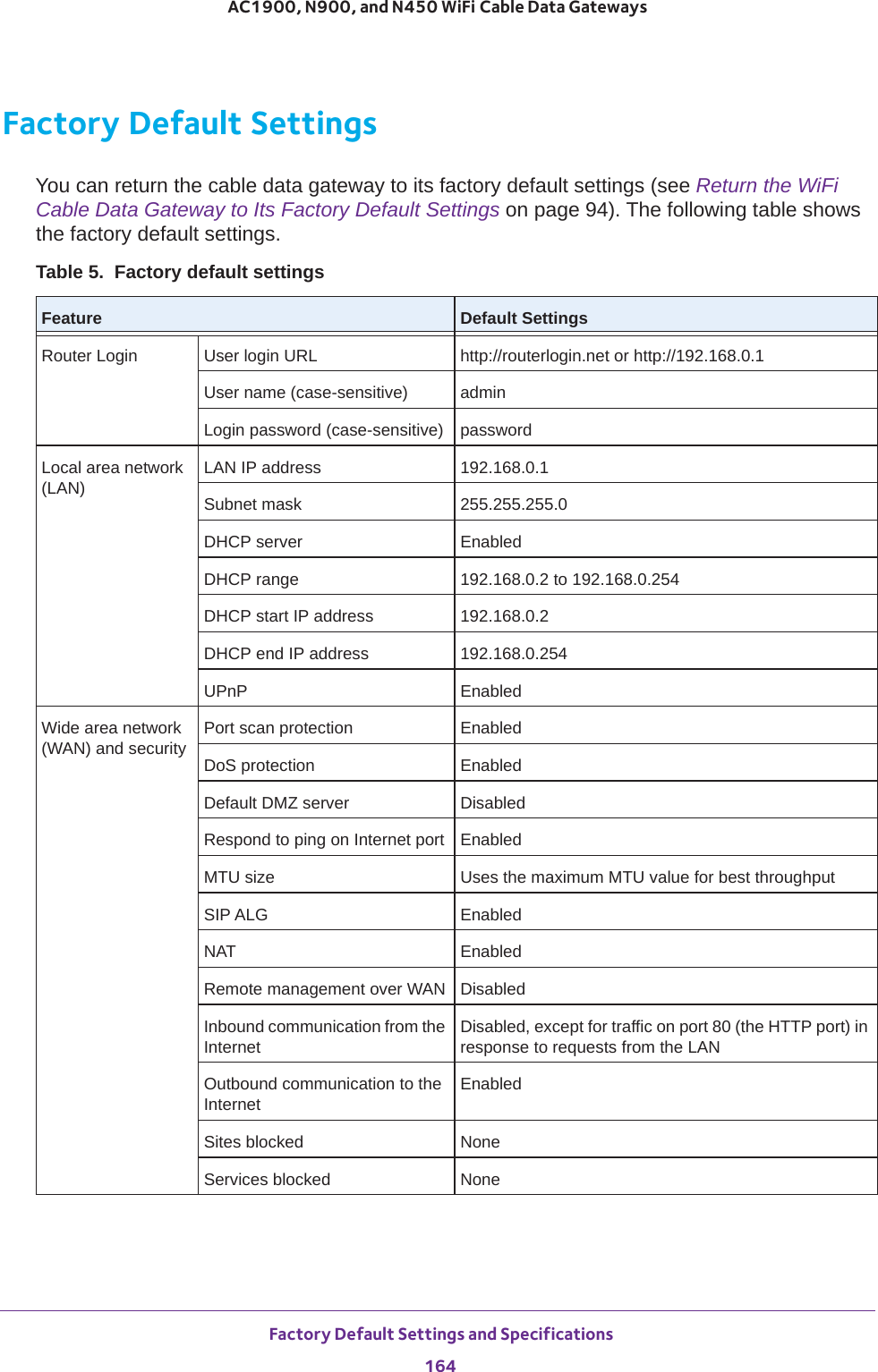
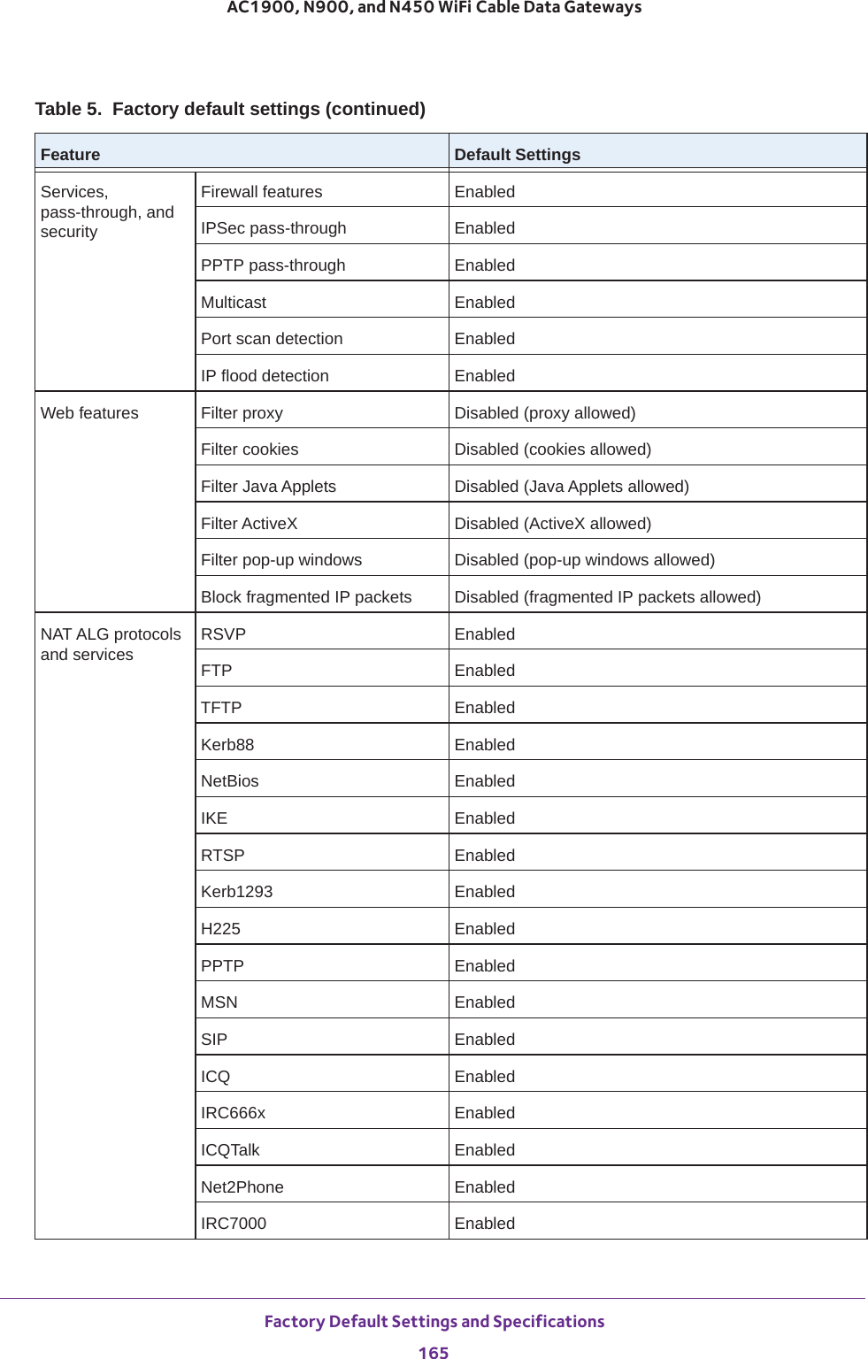
![Factory Default Settings and Specifications166AC1900, N900, and N450 WiFi Cable Data Gateways Main WiFi network WiFi radios1EnabledWiFi network names (SSIDs)1See the product labelWiFi passphrase for both SSIDs1See the product labelType of WiFi security WPA-PSK [TKIP] + WPA2-PSK [AES] Wireless isolation DisabledBroadcast SSID EnabledCountry/region Varies by regionRF channel AutoOperating mode2AC1900 WiFi Cable Data Gateway, Model C6300BD:• Default mode at 2.4 GHz: Up to 289 Mbps• Default mode at 5 GHz: Up to 1300 MbpsN900 WiFi Cable Data Gateway, Model CG4500BD:• Default mode at 2.4 GHz: Up to 289 Mbps• Default mode at 5 GHz: Up to 450 MbpsN450 WiFi Cable Data Gateway, Model CG3000Dv2:Default at 2.4 GHz: Up to 289 MbpsRadio transmission power 100 percent, nonconfigurable20/40 MHz coexistence Enabled, nonconfigurableFragmentation length 2346CTS/RTS threshold 2347Preamble mode Long preambleWPS WPS capability EnabledPIN Enabled, see the web management interface (path ADVANCED > Setup > Wireless Settings)Keep Existing Wireless Settings EnabledGuest WiFi network WiFi radios1DisabledWiFi network names (SSIDs)1See the product labelType of WiFi security none (open network)Enable SSID broadcast DisabledAllow guests to access local networkDisabled1. The N450 WiFi Cable Data Gateway, Model CG3000Dv2, support a single radio and SSID only.Table 5. Factory default settings (continued)Feature Default Settings](https://usermanual.wiki/Netgear-orporated/14200260.User-Manual-rev-pdf/User-Guide-2441000-Page-166.png)
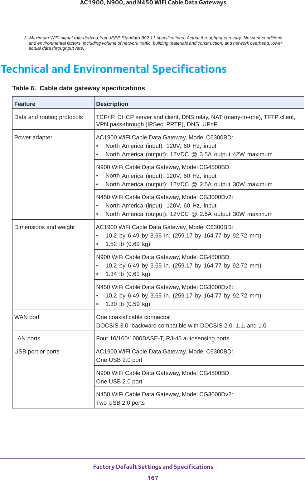
![Factory Default Settings and Specifications168AC1900, N900, and N450 WiFi Cable Data Gateways WiFi AC1900 WiFi Cable Data Gateway, Model C6300BD:• Up to 600 Mbps1 at 2.4 GHz for 802.11n/g/b devices• Up to 1300 Mbps1 at 5 GHz for 802.11ac/n/a devicesN900 WiFi Cable Data Gateway, Model CG4500BD:• Up to 450 Mbps1 at 2.4 GHz for 802.11n/g/b devices• Up to 450 Mbps1 at 5 GHz for 802.11n/a devicesN450 WiFi Cable Data Gateway, Model CG3000Dv2:Up to 450 Mbps1 at 2.4 GHz for 802.11n/g/b devicesWiFi channels • 2.4 GHz band: Auto or a single channel from 01–11• 5 GHz band:2 Auto or 36, 40, 44, 48, 149, 143, 157, or 161Maximum computers per WiFi networkLimited by the amount of WiFi network traffic generated by each nodeOperating frequency ranges • 2.4 GHz band: 2.412–2.462 GHz• 5 GHz band: 5.180-5.835 GHz2802.11 authorization and encryption• WPA2-PSK [AES]• WPA-PSK [TKIP] + WPA2-PSK [AES]Operating temperature 32° to 140°F (0° to 40°C)Operating humidity 90% maximum relative humidity, noncondensingElectromagnetic emissions FCCSafety standards UL 609501. Maximum WiFi signal rate derived from IEEE Standard 802.11 specifications. Actual throughput can vary. Network conditions and environmental factors, including volume of network traffic, building materials and construction, and network overhead, lower actual data throughput rate.2. Not applicable to the N450 WiFi Cable Data Gateway, Model CG3000Dv2.Table 6. Cable data gateway specifications (continued)Feature Description](https://usermanual.wiki/Netgear-orporated/14200260.User-Manual-rev-pdf/User-Guide-2441000-Page-168.png)