Netgear orporated 14200281 Outdoor High Power Wireless N Access Point User Manual
Netgear Incorporated Outdoor High Power Wireless N Access Point
Contents
- 1. User Manual.pdf
- 2. User Manual rev.pdf
User Manual.pdf
Installation
NETGEAR Outdoor High Power Wireless N
Access Point
WND930
Set Up the Access Point
Before mounting the access point in a high location, first set up and test the
unit to verify wireless network connectivity.
Note: The access point has a DHCP client enabled by default. If a DHCP server
exists in your network, the access point obtains an IP address from the DHCP
server. If a DHCP server is not detected in your network aer 30 seconds, the
access point sets its IP address to a static IP address of 192.168.0.100.
¾To cable your access point:
1. Using an Ethernet cable, connect a power sourcing equipment (PSE) to
a PoE port on the access point.
Note: You must supply either AT power to at least one LAN port or AF power
to two LAN ports to power the access point. You must supply AT power to
both LAN ports to receive PoE power out.
2. If a DHCP server is not connected to your network, configure a
computer with a static IP address of 192.168.0.210 and a subnet mask
of 255.255.255.0.
3. Connect an Ethernet cable from a LAN port on the access point to a
LAN port on the PC.
4. Check the LEDs to verify that the access point is set up correctly.
Package Contents
Unpack the box and verify the contents:
• Outdoor High Power Wireless N Access Point
• Wall mounting bracket
• Four bracket screws
• Two pole mount clamps
• Three weatherproof cable glands
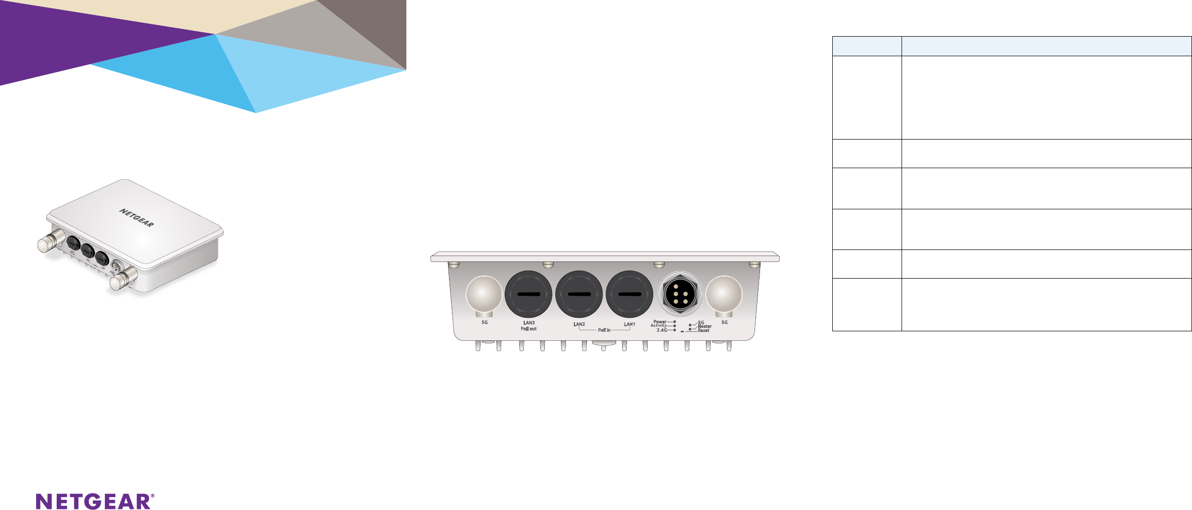
LED Description
Power LED •O. Power is o.
•Solid green. Power is on.
•Amber, then blinking green. A self-test is running or soware is being
loaded. During startup, the LED is first steady amber, then goes o, and
then blinks green before turning steady green aer about 45 seconds. If
aer one minute the LED remains amber or continues to blink green, it
indicates a system fault.
Activity LED •O. There is no network trac through the access point.
•Blinking green. There is network trac through the access point.
2.4G WLAN
LED
•O. The wireless interface is o.
•Solid green. The wireless interface is on.
•Blinking green. Wireless activity is detected on the 2.4G band.
5G WLAN LED •O. The wireless interface is o.
•Solid green. The wireless interface is on.
•Blinking green. Wireless activity is detected on the 5G band.
Heater LED •O. Heater is o.
•Solid green. Heater is on.
LAN port LEDs •O. No link is detected.
•Solid green. Link is detected.
•Solid amber. 10/100/1000 speed connection is detected.
•Blinking amber. 10/100/1000 speed activity is detected.
¾To configure your access point for your network:
1. Connect to the access point by opening your browser and entering the
access point’s IP address
If a DHCP server is not installed in your network, the default IP address is
192.168.0.100.
A login window displays.
2. Enter admin for the user name and password for the password, both in
lower case letters.
The access point user interface displays.
3. Select Configuration > System > Basic > General from the menu.
Operation temperature : -20℃ to +60℃
Operation voltage: Input: 44-57Vdc, 0.45A (per each PoE In)
Output: 51Vdc, 15.4W
August 2014
NETGEAR, Inc.
350 East Plumeria Drive
San Jose, CA 95134, USA
NETGEAR, the NETGEAR logo, and Connect with Innovation are trademarks and/or registered
trademarks of NETGEAR, Inc. and/or its subsidiaries in the United States and/or other countries.
Information is subject to change without notice. © NETGEAR, Inc. All rights reserved.
4. Complete the Access Point Name field and select your Country/
Region of operation from the drop-down list.
5. Select Configuration > IP > IP Settings from the menu and configure
the IP settings for your network.
Note: If you use DHCP, reserve an IP address (based on the access point’s
MAC address) on the DHCP server. You can then use that address to log in to
the access point.
6. Select Configuration > Wireless > Basic > Wireless Settings and
configure the wireless settings for your network.
For more information about wireless settings, see the reference manual.
7. Select Configuration > Security > Profile Settings and configure
security profiles for your network.
For more information about security profile settings, see the reference
manual.
Deploy the Access Point
The best location for your access point is elevated such as wall or ceiling
mounted, at the center of your wireless coverage area, and within line of
sight of all mobile devices.
¾To deploy your access point:
1. Disconnect your access point and position it where you will deploy it.
2. Connect an ethernet cable from your access point to a LAN port on
your router, switch or hub.
3. Connect a power sourcing equipment (PSE) to one of the PoE ports on
the access point.
If your router switch or hub supplies PoE, skip this step.
Note: You must supply either AT power to at least one LAN port or AF power
to two LAN ports to power the access point. You must supply AT power to both
LAN ports to receive PoE power out.
4. Using a wireless device, verify connectivity by using a browser to
connect to the Internet.
Problem Cause Possible Solution
You cannot
access the
Internet
or the
LAN from
a wireless
device.
A configuration
problem exists.
•Make sure that the SSID and wireless security settings
of the wireless device are the same as those of the
access point.
•ThewirelessdevicemightnothavethecorrectTCP/IP
settings to communicate with the network. Restart the
wireless device and check that TCP/IP is set up correctly
for that network.
•Theaccesspointdefaultvaluesmightnotwork
with your network. Check the access point default
configuration against the configuration of other devices
in your network. For information about changing the
default values of the access point, see the reference
manual.
Support
Thank you for selecting NETGEAR products. Aer installing your device, locate
the serial number on the label of your product and use it to register your
product at https://my.netgear.com.
You must register your product before you can use NETGEAR telephone
support. NETGEAR recommends registering your product through the NETGEAR
website. For product updates and web support, visit
http://support.netgear.com.
NETGEAR recommends that you use only the ocial NETGEAR support
resources.
For the current EU Declaration of Conformity, visit
http://support.netgear.com/app/answers/detail/a_id/11621/.
For regulatory compliance information, visit
http://www.netgear.com/about/regulatory/.
See the regulatory compliance document before connecting the power supply.
Optional External Antennas
The WND930 supports optional external antennas.
¾To install optional external 2G or 5G antennas:
1. Attach the 2G or 5G antennas to the corresponding connectors on the
side panels of the access point.
2. Log into the access point and configure it to use the external antennas.
Troubleshooting Tips
This section provides some tips for correcting simple problems that
you might encounter. For more troubleshooting information, see the
troubleshooting chapter in the reference manual.
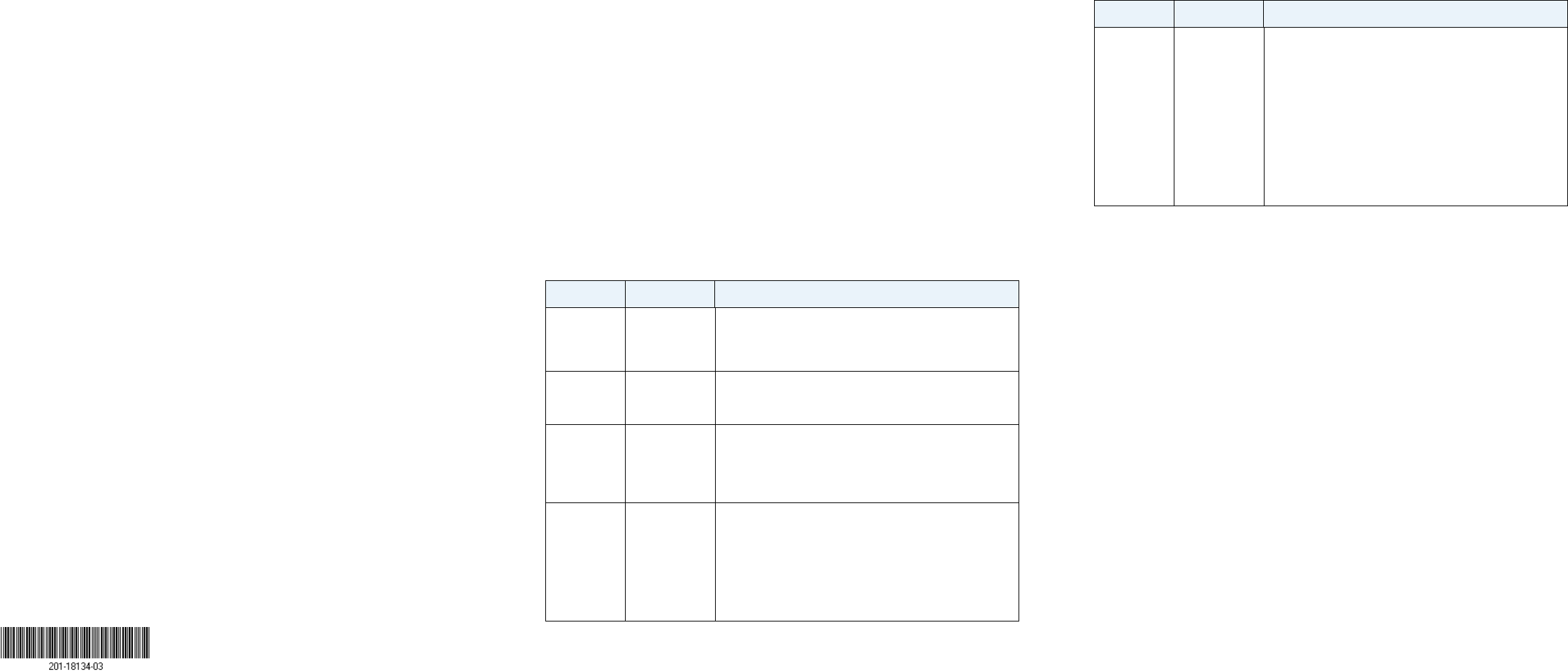
Problem Cause Possible Solution
No LEDs are
lit on the
access point.
The access
point has no
power.
•Makesurethatapowersourceequipment(PSE)is
connected via Ethernet to at least one PoE port.
•Make sure that the power source equipment (PSE) is
powered on.
The LAN LED
is o.
A hardware
connection
problem exists.
•Makesurethatthecableconnectorsaresecurely
plugged into the access point and to the network switch.
Make sure that the network switch is turned on.
The Wireless
LED is o.
The wireless
connection
does not work.
•Makesurethepowereddeviceisprovidingsucient
power to the access point.
•Logintotheaccesspointandverifythattheradioor
radios are turned on.
•ContactNETGEARiftheWirelessLEDremainso.
You cannot
configure
the access
point from a
browser.
Multiple
possible
causes.
•Make sure that the access point is correctly installed, it
is powered on, and that the LAN LED is lit.
•MakesurethatyourcomputerisusinganIPaddress
in the same range as the access point. The access point
default IP address is 192.168.0.100, and the default
subnet mask is 255.255.255.0.
•Quitthebrowser,clearthecache,deletethecookies,
and launch the browser again.
Federal Communication Commission Interference Statement
This device complies with Part 15 of the FCC Rules. Operation is subject to
the following two conditions: (1) This device may not cause harmful
interference, and (2) this device must accept any interference received,
including interference that may cause undesired operation.
This equipment has been tested and found to comply with the limits for a
Class B digital device, pursuant to Part 15 of the FCC Rules. These limits are
designed to provide reasonable protection against harmful interference in a
residential installation. This equipment generates, uses and can radiate radio
frequency energy and, if not installed and used in accordance with the
instructions, may cause harmful interference to radio communications.
However, there is no guarantee that interference will not occur in a
particular installation. If this equipment does cause harmful interference
to radio or television reception, which can be determined by turning the
equipment off and on, the user is encouraged to try to correct the
interference by one of the following measures:
- Reorient or relocate the receiving antenna.
- Increase the separation between the equipment and receiver.
- Connect the equipment into an outlet on a circuit different from that
to which the receiver is connected.
- Consult the dealer or an experienced radio/TV technician for help.
FCC Caution: Any changes or modifications not expressly approved by the
party responsible for compliance could void the user's authority to operate
this equipment.
This transmitter must not be co-located or operating in conjunction with any
other antenna or transmitter.
For operation within 5.15 ~ 5.25GHz / 5.47 ~5.725GHz frequency range, it is
restricted to indoor environment. The band from 5600-5650MHz will be
disabled by the software during the manufacturing and cannot be changed by
the end user. This device meets all the other requirements specified in Part
15E, Section 15.407 of the FCC Rules.
Radiation Exposure Statement:
This equipment complies with FCC radiation exposure limits set forth for an
uncontrolled environment. This equipment should be installed and operated
with minimum distance 26cm between the radiator & your body.
Professional installation instruction
1. Installation personal
This product is designed for specific application and needs to be installed by a
qualified personal who has RF and related rule knowledge. The general user shall not
attempt to install or change the setting.
2. Installation location
The product shall be installed at a location where the radiating antenna can be kept
26 from nearby person in normal operation condition to meet regulatory RF exposure
requirement.
3. External antenna
Use only the antennas which have been approved by the applicant. The
non-approved antenna(s) may produce unwanted spurious or excessive RF
transmitting power which may lead to the violation of FCC/IC limit and is prohibited.
4. Installation procedure
Please refer to user’s manual for the detail.
5. Warning
Please carefully select the installation position and make sure that the final output
power does not exceed the limit set force in relevant rules. The violation of the rule
could lead to serious federal penalty.
1. Installation
Ce produit est destine a un usage specifique et doit etre installe par un personnel
qualifie maitrisant les radiofrequences et les regles s'y rapportant. L'installation et
les reglages ne doivent pas etre modifies par l'utilisateur final.
2. Emplacement d'installation
En usage normal, afin de respecter les exigences reglementaires concernant
l'exposition aux radiofrequences, ce produit doit etre installe de facon a respecter
une distance de 26 cm entre l'antenne emettrice et les personnes.
3. Antenn externe.
Utiliser uniiquement les antennes approuvees par le fabricant. L'utilisation d'autres
antennes peut conduire a un niveau de rayonnement essentiel ou non essentiel
depassant les niveaux limites definis par FCC/IC, ce qui est interdit.
4. Procedure d'installation
Consulter le manuel d'utilisation.
5. Avertissement
Choisir avec soin la position d'installation et s'assurer que la puissance de sortie ne
depasse pas les limites en vigueur. La violation de cette regle peut conduire a de
serieuses penalites federales.
Industry Canada statement:
This device complies with RSS-210 of the Industry Canada Rules. Operation is subject
to the following two conditions: (1) This device may not cause harmful interference,
and (2) this device must accept any interference received, including interference
that may cause undesired operation.
Ce dispositif est conforme à la norme CNR-210 d'Industrie Canada applicable aux
appareils radio exempts de licence. Son fonctionnement est sujet aux deux
conditions suivantes: (1) le dispositif ne doit pas produire de brouillage préjudiciable,
et (2) ce dispositif doit accepter tout brouillage reçu, y compris un brouillage
susceptible de provoquer un fonctionnement indésirable.
Caution :
(i) the device for operation in the band 5150-5250 MHz is only for indoor use to
reduce the potential for harmful interference to co-channel mobile satellite
systems;
(ii) the maximum antenna gain permitted for devices in the bands 5250-5350 MHz
and 5470-5725 MHz shall comply with the e.i.r.p. limit; and
(iii) the maximum antenna gain permitted for devices in the band 5725-5825 MHz
shall comply with the e.i.r.p. limits specified for point-to-point and non
point-to-point operation as appropriate.
(iv) Users should also be advised that high-power radars are allocated as primary
users (i.e. priority users) of the bands 5250-5350 MHz and 5650-5850 MHz and that
these radars could cause interference and/or damage to LE-LAN devices.
Avertissement:
Le guide d’utilisation des dispositifs pour réseaux locaux doit inclure des instructions
précises sur les restrictions susmentionnées, notamment :
(i) les dispositifs fonctionnant dans la bande 5 150-5 250 MHz sont réservés
uniquement pour une utilisation à l’intérieur afin de réduire les risques de brouillage
préjudiciable aux systèmes de satellites mobiles utilisant les mêmes canaux;
(ii) le gain maximal d’antenne permis pour les dispositifs utilisant les bandes 5 250-5
350 MHz et 5 470-5 725 MHz doit se conformer à la limite de p.i.r.e.;
(iii) le gain maximal d’antenne permis (pour les dispositifs utilisant la bande 5 725-5
825 MHz) doit se conformer à la limite de p.i.r.e. spécifiée pour l’exploitation point
à point et non point à point, selon le cas.
(iv) De plus, les utilisateurs devraient aussi être avisés que les utilisateurs de radars
de haute puissance sont désignés utilisateurs principaux (c.-à-d., qu’ils ont la
priorité) pour les bandes 5 250-5 350 MHz et 5 650-5 850 MHz et que ces radars
pourraient causer du brouillage et/ou des dommages aux dispositifs LAN-EL.
Radiation Exposure Statement:
This equipment complies with IC radiation exposure limits set forth for an
uncontrolled environment. This equipment should be installed and operated with
minimum distance 26cm between the radiator & your body.
Déclaration d'exposition aux radiations:
Cet équipement est conforme aux limites d'exposition aux rayonnements IC établies
pour un environnement non contrôlé. Cet équipement doit être installé et utilisé
avec un minimum de 26 cm de distance entre la source de rayonnement et votre
corps.
This device has been designed to operate with an antenna having a maximum gain of
[7] dB. Antenna having a higher gain is strictly prohibited per regulations of Industry
Canada. The required antenna impedance is 50 ohms.
Under Industry Canada regulations, this radio transmitter may only operate using an
antenna of a type and maximum (or lesser) gain approved for the transmitter by
Industry Canada. To reduce potential radio interference to other users, the antenna
type and its gain should be so chosen that the equivalent isotropically radiated power
(e.i.r.p.) is not more than that necessary for successful communication.
This radio transmitter (IC: 4054A-14200281 / Model: WND930) has been approved
by Industry Canada to operate with the antenna types listed below with the maximum
permissible gain and required antenna impedance for each antenna type indicated.
Antenna types not included in this list, having a gain greater than the maximum gain
indicated for that type, are strictly prohibited for use with this device.
Ce dispositif a été conçu pour fonctionner avec une antenne ayant un gain maximal de
dB [7]. Une antenne à gain plus élevé est strictement interdite par les règlements
d'Industrie Canada. L'impédance d'antenne requise est de 50 ohms.
Conformément à la réglementation d'Industrie Canada, le présent émetteur radio
peutfonctionner avec une antenne d'un type et d'un gain maximal (ou inférieur)
approuvé pourl'émetteur par Industrie Canada. Dans le but de réduire les risques de
brouillage radioélectriqueà l'intention des autres utilisateurs, il faut choisir le type
d'antenne et son gain de sorte que lapuissance isotrope rayonnée équivalente (p.i.r.e.)
ne dépasse pas l'intensité nécessaire àl'établissement d'une communication
satisfaisante.
Le présent émetteur radio (IC: 4054A-14200281 / Model: WND930) a été approuvé
par Industrie Canada pour fonctionner avec les types d'antenne énumérés ci-dessous et

ayant un gain admissible maximal et l'impédance requise pour chaque type d'antenne.
Les types d'antenne non inclus dans cette liste, ou dont le gain est supérieur au gain
maximal indiqué, sont strictement interdits pour l'exploitation de l'émetteur.
Approved antenna(s) list
Antenna
Gain(dBi)
Frequencyrange(MHztoMHz) AntennaType
Connecter
Type
52.4~2.4835GHzDipoleNtype(M)
52.4~2.4835GHzDipoleNtype(M)
75.150~5.850GHz DipoleNtype(M)
75.150~5.850GHz DipoleNtype(M)