Netgear orporated 15300321 ProSAFE Dual Band Wireless AC Access Point User Manual rev
Netgear Incorporated ProSAFE Dual Band Wireless AC Access Point rev
User Manual_rev.pdf
Installation Guide
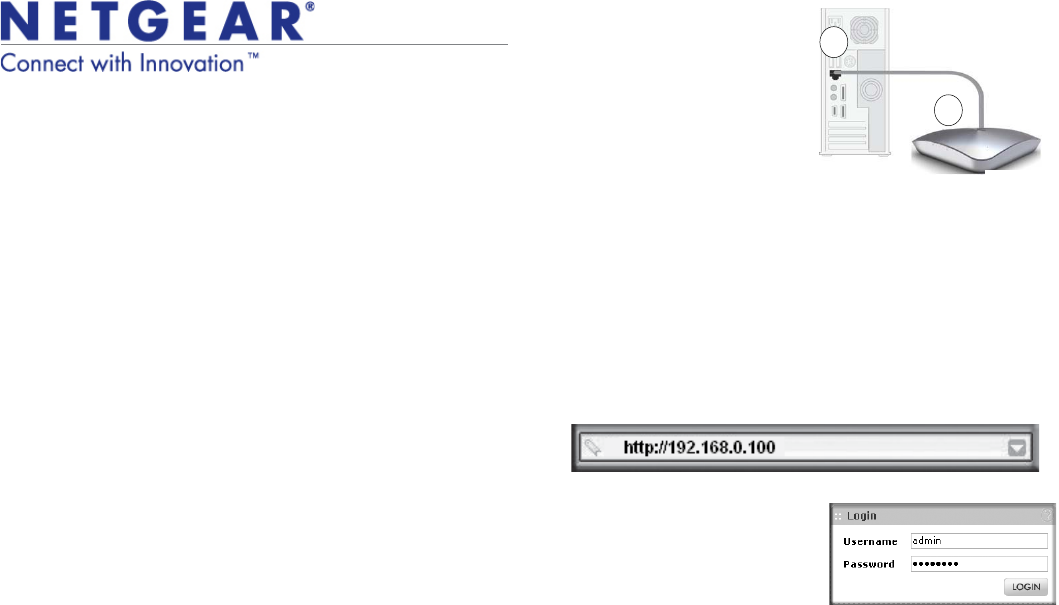
b. Connect an Ethernet cable from
the access point to the PC (point
Ain the illustration).
c. Securely insert the other end of
the cable into the access point
Ethernet port (point Bin the
illustration).
d. Connect the power adapter to the
access point and verify the
following:
•Power. The Power LED blinks
when the access point is first
turned on. After a few seconds it should stay on (steady green). If after 30
seconds the Power LED is off or is still blinking, check the connections
and check to see if the power outlet is controlled by a wall switch that is
turned off.
•ACTIVE. The ACTIVE LED blinks when there is network traffic.
•LAN. The LAN LED indicates LAN speeds; green for 1000 Mbps, amber
for 100Mbps, and no light for 10Mbps.
•2.4G Hz (WLAN). This LED indicates 2.4 G Hz traffic.
•5 G Hz (WLAN). This LED indicates 5 G Hz traffic.
2. Configure LAN and wireless access
a. From your PC, configure the access point Ethernet port for LAN access.
Connect to the access point by opening your browser and entering
http://192.168.0.100 in the address field.
b. A login window displays. When
prompted, enter admin for the user
name and password for the
password, both in lower case
letters.
The access point user interface
displays.
NETGEAR Cable
A
B
WNDAP360
Ethernet
port
c. Select Configuration > System > Basic > General from the menu. Fill in
the Access Point Name field and select your Country/Region of operation
from the drop-down list.
d. Select Configuration > IP > IP Settings from the menu and configure the
IP settings for your network.
e. If you use DHCP, reserve an IP address (based on the access point’s MAC
address) on the DHCP server. You can then use that address to log in to
the access point.
f. Select Configuration > Wireless > Basic > Wireless Settings and select
the Turn Radio On setting.
g. Select Configuration > Security > Profile Settings and configure security
profiles for your network.
See the online help or the Reference Manual for full instructions.
3. Test wireless connectivity.
Using a PC with a wireless adapter, verify that you can establish a wireless
connection to the access point.
Now that you have finished the setup, you are ready to deploy the access point
in your network. If needed, you can reconfigure the PC you used in step 1 back
to its original TCP/IP settings.
Deploy the Access Point
1. Disconnect the access point and position it where you will deploy it. The best
location is elevated such as wall or ceiling mounted, at the center of your
wireless coverage area, and within line of sight of all mobile devices.
2. Connect an Ethernet cable from your access point to a LAN port on your
router, switch, or hub.
3. Connect the power adapter to the wireless access point and plug the power
adapter into a power outlet. The Power and LAN LEDs should go on.
Tip: The access point supports Power over Ethernet (PoE). If you have
a switch that provides PoE, you do not need to use the power adapter
to power the access point. This can be especially convenient when the
access point is installed in a high location far from a power outlet.
ProSafe® Dual Band Wireless-N Access Point WNDAP360
Package Contents
Unpack the box and verify the contents:
•ProSafe® Dual Band Wireless-N Access Point WNDAP360
•Straight through Category 5 Ethernet cable
•Power adapter and cord (12V, 1A)
•Wall mount kit
•Installation Guide
•Resource CD, which includes link to the Reference Manual
Set Up the Access Point
Follow these instructions to set up your wireless access point. Before proceeding
with the WNDAP360 installation, familiarize yourself with the contents of the
Resource CD. See the Reference Manual for instructions on advanced
configuration options.
Estimated Completion Time: 3 minutes.
Tip: Before mounting the access point in a high location, first set up
and test the unit to verify wireless network connectivity.
1. Connect the wireless access point to your computer.
a. Prepare a PC with an Ethernet adapter. If this PC is already part of your
network, record its TCP/IP configuration settings. Configure the PC with a
static IP address of 192.168.0.210 and 255.255.255.0 as the subnet mask.
WAC730

February 2011
This symbol was placed in accordance with the European Union Directive 2002/96 on the Waste
Electrical and Electronic Equipment (the WEEE Directive). If disposed of within the European Union,
this product should be treated and recycled in accordance with the laws of your jurisdiction
implementing the WEEE Directive.
©2011 by NETGEAR, Inc. All rights reserved. NETGEAR, the NETGEAR logo, and ProSafe® are registered
trademarks of NETGEAR, Inc. in the United States and/or other countries. Other brand and product names are
trademarks or registered trademarks of their respective holders. Information is subject to change without notice.
Verify Wireless Connectivity
Using a computer with an 802.11b/g/n wireless adapter, verify connectivity by using
a browser to connect to the Internet, or check for file and printer access on your
network.
Note: If you cannot connect, see Troubleshooting Tips in this guide or the
Reference Manual.
If You Use an External Antenna
To use an external 2.4 GHz antenna:
1. Mount the accessory antenna(s).
2. Attach the antenna(s) to the connector(s) on the access point rear panel.
3. Log into the access point and configure it to use the external antenna. The
access point cannot use the internal and external 2.4GHz antennas at the
same time.
Troubleshooting Tips
Here are some tips for correcting simple problems you may have.
No LEDs are lit on the access point.
The wireless access point has no power.
•Make sure the power cord is connected to the wireless access point and
plugged in to a working power outlet or power strip.
•Make sure you are using the correct NETGEAR power adapter supplied with
your wireless access point.
•If using PoE, ensure that the PoE switch is providing power to the access point.
The LINK/ACT LED is not on.
There is a hardware connection problem.
•Make sure the cable connectors are securely plugged in to the access point and
to the network device (hub, switch, or router).
•Make sure the connected device is turned on. If the Ethernet link is a 10 Mbps
link, then the 10/100/1000 light is off, but the Link/Act light blinks if traffic is
present.
The WLAN LEDs are off.
The wireless connection is not working.
•If a Wireless LAN activity LED stays off, disconnect the power adapter from its
power source and then plug it in again.
•Log in to the access point and verify that the radio is turned on.
•Contact NETGEAR if the Wireless LAN LED remains off.
I cannot configure the access point from a browser.
Check these items:
•The access point is correctly installed, it is powered on, and LAN connections
are OK. Check that the LAN LED is on to verify that the Ethernet connection is
OK.
•If you are using the Net BIOS name of the access point to connect, ensure that
your PC and the access point are on the same network segment or that there is
a WINS server on your network.
•If your PC uses a fixed (static) IP address, ensure that it is using an IP address
in the range of the access point. The access point default IP address is
192.168.0.100 and the default subnet mask is 255.255.255.0. The access point
default setting is for a static IP address. If the network where you are connecting
it is using DHCP, configure it accordingly. See the Reference Manual for details.
I cannot access the Internet or the LAN with a wireless capable
computer.
There is a configuration problem. Check these items:
•You might not have restarted the computer with the wireless adapter to have
TCP/IP changes take effect. Restart the computer.
•The computer with the wireless adapter might not have the correct TCP/IP
settings to communicate with the network. Restart the computer and check that
TCP/IP is set up correctly for that network. The usual setting for Windows on the
Network Properties is set to “Obtain an IP address automatically.”
•The wireless access point’s default values might not work with your network.
Check the wireless access point default configuration against the configuration
of other devices in your network.
•For full instructions on changing the default values of the wireless access point,
see the Reference Manual.
Statement of Conditions
In the interest of improving internal design, operational function, and/operability,
NETGEAR reserves the right to make changes to the product described in this
document without notice. NETGEAR does not assume any liability that may occur
due to the use or application of the product(s) or circuit layout(s) described herein.
Technical Support
Thank you for selecting NETGEAR products.
After installing your device, locate the serial number on the label of your product and
use it to register your product at http://www.netgear.com/register. Registration is
required before you can use our telephone support service. Registration via our web
site is strongly recommended.
Go to http://kbserver.netgear.com for product updates and Web support. For
Warranty and Regional Customer Support information, see the Resource CD that
came with your product.
For complete DoC please visit the NETGEAR EU Declarations of Conformity
website at: http://kb.netgear.com/app/answers/detail/a_id/11621/
Federal Communication Commission Interference Statement
This device complies with Part 15 of the FCC Rules. Operation is subject to
the following two conditions: (1) This device may not cause harmful
interference, and (2) this device must accept any interference received,
including interference that may cause undesired operation.
This equipment has been tested and found to comply with the limits for a
Class B digital device, pursuant to Part 15 of the FCC Rules. These limits are
designed to provide reasonable protection against harmful interference in a
residential installation. This equipment generates, uses and can radiate radio
frequency energy and, if not installed and used in accordance with the
instructions, may cause harmful interference to radio communications.
However, there is no guarantee that interference will not occur in a
particular installation. If this equipment does cause harmful interference to
radio or television reception, which can be determined by turning the
equipment off and on, the user is encouraged to try to correct the
interference by one of the following measures:
- Reorient or relocate the receiving antenna.
- Increase the separation between the equipment and receiver.
- Connect the equipment into an outlet on a circuit different from that
to which the receiver is connected.
- Consult the dealer or an experienced radio/TV technician for help.
FCC Caution: Any changes or modifications not expressly approved by the
party responsible for compliance could void the user's authority to operate
this equipment.
This transmitter must not be co-located or operating in conjunction with any
other antenna or transmitter.
For operation within 5.15 ~ 5.25GHz frequency range, it is restricted to
indoor environment.

Radiation Exposure Statement:
This equipment complies with FCC radiation exposure limits set forth for an
uncontrolled environment. This equipment should be installed and operated
with minimum distance 20cm between the radiator & your body.
Industry Canada statement:
This device complies with RSS-210 of the Industry Canada Rules. Operation is
subject to the following two conditions: (1) This device may not cause
harmful interference, and (2) this device must accept any interference
received, including interference that may cause undesired operation.
Ce dispositif est conforme à la norme CNR-210 d'Industrie Canada applicable
aux appareils radio exempts de licence. Son fonctionnement est sujet aux
deux conditions suivantes: (1) le dispositif ne doit pas produire de brouillage
préjudiciable, et (2) ce dispositif doit accepter tout brouillage reçu, y
compris un brouillage susceptible de provoquer un fonctionnement
indésirable.
Caution :
(i) the device for operation in the band 5150-5250 MHz is only for indoor use
to reduce the potential for harmful interference to co-channel mobile
satellite systems;
(ii) high-power radars are allocated as primary users (i.e. priority users) of
the bands 5250-5350 MHz and 5650-5850 MHz and that these radars could
cause interference and/or damage to LE-LAN devices.
Avertissement:
les dispositifs fonctionnant dans la bande 5 150-5 250 MHz sont réservés
uniquement pour une utilisation à l’intérieur afin de réduire les risques de
brouillage préjudiciable aux systèmes de satellites mobiles utilisant les
mêmes canaux;
(ii) De plus, les utilisateurs devraient aussi être avisés que les utilisateurs de
radars de haute puissance sont désignés utilisateurs principaux (c.-à-d.,
qu’ils ont la priorité) pour les bandes 5 250-5 350 MHz et 5 650-5 850 MHz et
que ces radars pourraient causer du brouillage et/ou des dommages aux
dispositifs LAN-EL.
Radiation Exposure Statement:
This equipment complies with IC radiation exposure limits set forth for an
uncontrolled environment. This equipment should be installed and operated
25
RSS-247
CNR-247

with minimum distance 20cm between the radiator & your body.
Déclaration d'exposition aux radiations:
Cet équipement est conforme aux limites d'exposition aux rayonnements IC
établies pour un environnement non contrôlé. Cet équipement doit être
installé et utilisé avec un minimum de 20 cm de distance entre la source de
rayonnement et votre corps.
30
30