Netgear orporated 17200376 AC WiFi Business Access Point User Manual rev
Netgear Incorporated AC WiFi Business Access Point rev
User Manual rev.pdf
Installation
Set Up the Access Point
The following table shows the dierent setup options that are available to
you and the requirements for the access point (AP).
Setup Option Connect
Over
Power
Source
Mode Extra
Requirements
Setup
Information
AP to Ethernet
PoE Switch
WAN port PoE AP mode None See this guide
AP to Ethernet
non-PoE Switch
WAN port Power
adapter
AP mode Order a power
adapter
See the user
manual
AP to DSL or cable
Internet modem
WAN port Power
adapter
Router
mode
Order a power
adapter
Change to
Router mode
See the user
manual
Note: For more information about the various setup options, see the
NETGEAR AC WiFi Business Access Point (WAC510) User Manual.
Before mounting the access point in a high location, first set up, configure,
and test the access point to verify WiFi network connectivity.
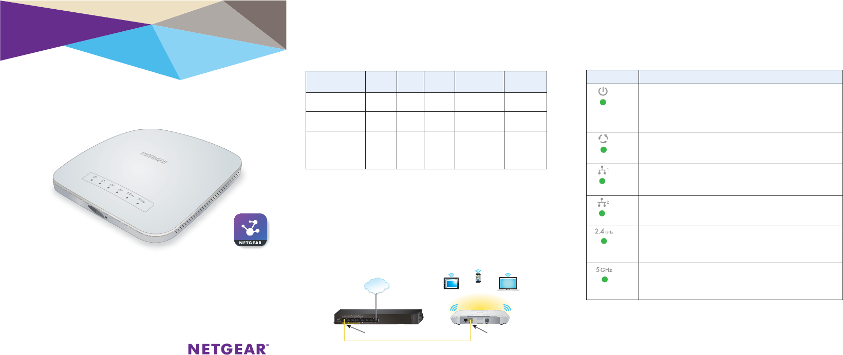
¾To set up the access point with a PoE switch:
Connect an Ethernet cable from the yellow WAN port on the access
point to a Power over Ethernet (PoE) switch.
The WAN port on the access point also functions as a PoE port. In this
setup, the access point does not require a power adapter.
AC WiFi Business Access Point (WAC510)
with NETGEAR Insight app for easy management
Package Contents
Unpack the box and verify the contents:
• NETGEAR® AC WiFi Business Access Point (WAC510)
• Installation guide
• Ceiling and wall installation kit
• Mounting installation guide
The following table shows the LED behavior on the access point.
LED Description
Power LED
•O. Power is o.
•Solid green. Power is on and the access point is ready.
•Solid amber. During startup, the Power LED lights solid amber.
If aer 5 minutes the LED remains solid amber, a boot error occurred.
•Fast blinking amber. Firmware update in progress.
Activity LED
•O. No link with the network is detected.
•Solid green. A link with the network is detected.
•Blinking green. Network trac is detected.
WAN LED
•O. No Ethernet link is detected.
•Solid amber. A 10/100 Mbps Ethernet link is detected.
•Solid green. A 1000 Mbps Ethernet link is detected.
LAN LED
•O. No Ethernet link is detected.
•Solid amber. A 10/100 Mbps Ethernet link is detected.
•Solid green. A 1000 Mbps Ethernet link is detected.
2.4G WLAN LED
•O. The 2.4 GHz WiFi radio is o.
•Solid green. The 2.4 GHz WiFi radio is on.
•Solid blue. One or more WLAN clients are connected to the 2.4 GHz radio.
•Blinking blue. WLAN trac is detected on the 2.4 GHz radio..
5G WLAN LED
•O. The 5 GHz WiFi radio is o.
•Solid green. The 5 GHz WiFi radio is on.
•Solid blue. One or more WLAN clients are connected to the 5 GHz radio.
•Blinking blue. WLAN trac is detected on the 5 GHz radio.
k
Note: Cable
not included. WAN port (also PoE port)PoE port on a PoE switch
Internet
WAC505
WAC505
April 2017
© NETGEAR, Inc., NETGEAR and the NETGEAR Logo
are trademarks of NETGEAR, Inc. Any non-NETGEAR
trademarks are used for reference purposes only.
NETGEAR, Inc.
350 East Plumeria Drive
San Jose, CA 95134, USA
NETGEAR INTL LTD
Building 3, University Technology Centre
Curraheen Road, Cork, Ireland
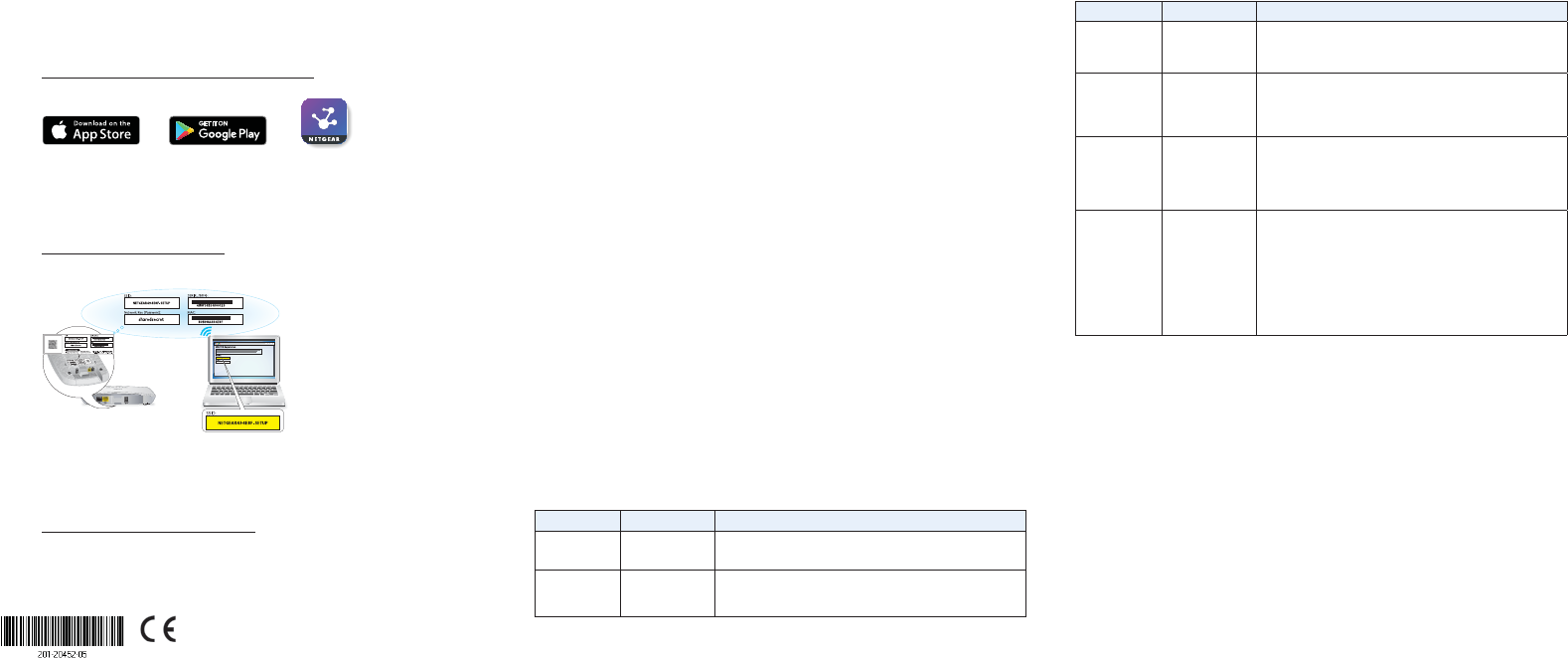
Configure the Access Point
¾Choose one of the following methods to configure the access point:
• Method 1: Use the NETGEAR Insight app. On your iOS or
Android mobile device, go to the app store. Search for NETGEAR
Insight, and download the app.
Open the NETGEAR Insight app and log in to your existing NETGEAR
account or create a new account to log in with. Then, follow the
prompts in the NETGEAR Insight app to discover and register the
access point on the network so that you can configure and manage
the access point.
• Method 2: Log in over WiFi. From your computer or mobile
device, connect over WiFi to the access point’s default SSID. The
default SSID is on the
access point label on the
bottom of the access point
and is shown in the format
NETGEARxxxxxx-SETUP.
The default password is
sharedsecret.
Open a web browser. In
the address bar, enter
www.routerlogin.net
(or www.aplogin.net). The Day Zero Easy Setup page displays so
that you can configure the basic settings, including the country of
operation. Aer you save these basic settings, the Day Zero Easy
Setup page no longer displays when you log in.
• Method 3: Log in over Ethernet. Open a web browser from a
computer that is connected to the same Ethernet subnet as the
access point or to the access point’s LAN port directly through an
Ethernet cable.
In the address bar, enter the IP address of the access point.
Problem Cause Possible Solution
The WAN or
LAN port LEDs
are o.
A hardware
connection
problem exists.
•Make sure that the cable connectors are securely plugged into
the AP and the switch.
• Make sure that the switch is turned on.
The WLAN LEDs
are o.
The WiFi
connection does
not work.
•Make sure that the PoE switch is providing sucient power to
the AP.
•Verify that the radio or radios are turned on.
•If the WLAN LEDs remain o, contact NETGEAR.
You cannot
connect to
the AP from a
browser.
Multiple possible
causes.
•Make sure that your computer is using an IP address in the same
subnet as the AP. The AP default IP address is 192.168.0.100, and
the default subnet mask is 255.255.255.0.
•Quit the browser, clear the cache, delete the cookies, and launch
the browser again.
You cannot
access the
Internet or the
LAN from a WiFi
device.
A configuration
problem exists.
•Make sure that the SSID and WiFi security settings of the WiFi
device are the same as those of the AP.
•The device might not be configured for the correct TCP/IP
settings to communicate with the network. Restart the device
and check that the TCP/IP settings are set up correctly for the
network.
•The AP default values might not work with your network. Check
the access point default configuration against the configuration of
other devices in your network.
Support
Thank you for purchasing this NETGEAR product. You can visit
www.netgear.com/support to register your product, get help, access the latest
downloads and user manuals, and join our community. We recommend that you
use only ocial NETGEAR support resources.
For more information about the installation and configuration options, visit
www.netgear.com/support to access the user manual.
For the current EU Declaration of Conformity, visit
http://support.netgear.com/app/answers/detail/a_id/11621/.
For regulatory compliance information, visit
http://www.netgear.com/about/regulatory/.
See the regulatory compliance document before providing power to the access point.
Note: If the access point is connected to a network that includes a DHCP
server (or router that functions as a DHCP server), determine the IP address
by using an IP network scanner. Otherwise, the default IP address of the
access point is 192.168.0.100. If you use an Ethernet cable from your
computer to the access point’s LAN port and the access point functions with
its default IP address, make sure that the IP address of your computer is in
the 192.168.0.x subnet.
The Day Zero Easy Setup page displays so that you can configure
the basic settings, including the country of operation. Aer you
save these basic settings, the Day Zero Easy Setup page no longer
displays when you log in.
Deploy the Access Point
The best location for the access point is elevated, such as mounted on a wall
or ceiling, at the center of the WiFi coverage area, and within line of sight of
all mobile devices.
For information about mounting the access point, see the NETGEAR AC WiFi
Business Access Point (WAC510) Ceiling and Wall Installation Guide.
¾To deploy the access point:
1. Disconnect the access point and position it where you will deploy it.
2. Reconnect the access point. See Set Up the Access Point.
3. Using a WiFi device, verify connectivity by connecting to the access
point and using a browser to connect to the Internet.
Troubleshooting Tips
The following table provides some tips for correcting simple problems
that you might encounter. For more troubleshooting information, see the
NETGEAR AC WiFi Business Access Point (WAC510) User Manual.
Problem Cause Possible Solution
No LEDs are lit
on the AP.
The AP is not
receiving power.
•Make sure that the AP is securely connected to a PoE switch.
•Make sure that the PoE switch is connected to a power source.
The Power LED
alternates green
and amber.
The AP is receiving
insucient PoE
power.
•Make sure that PoE switch is not overloaded.
•Connect to a power source such as a 12V 2.5 A power adapter.
WAC505
WAC505
Federal Communication Commission Interference Statement
This device complies with Part 15 of the FCC Rules. Operation is subject to
the following two conditions: (1) This device may not cause harmful
interference, and (2) this device must accept any interference received,
including interference that may cause undesired operation.
This equipment has been tested and found to comply with the limits for a
Class B digital device, pursuant to Part 15 of the FCC Rules. These limits are
designed to provide reasonable protection against harmful interference in a
residential installation. This equipment generates, uses and can radiate radio
frequency energy and, if not installed and used in accordance with the
instructions, may cause harmful interference to radio communications.
However, there is no guarantee that interference will not occur in a
particular installation. If this equipment does cause harmful interference to
radio or television reception, which can be determined by turning the
equipment off and on, the user is encouraged to try to correct the
interference by one of the following measures:
- Reorient or relocate the receiving antenna.
- Increase the separation between the equipment and receiver.
- Connect the equipment into an outlet on a circuit different from that
to which the receiver is connected.
- Consult the dealer or an experienced radio/TV technician for help.
FCC Caution: Any changes or modifications not expressly approved by the
party responsible for compliance could void the user's authority to operate
this equipment.
This transmitter must not be co-located or operating in conjunction with any
other antenna or transmitter.
For operation within 5.15 ~ 5.25GHz frequency range, it is restricted to
indoor environment.
Radiation Exposure Statement:
This equipment complies with FCC radiation exposure limits set forth for an
uncontrolled environment. This equipment should be installed and operated
with minimum distance 22cm between the radiator & your body.
Industry Canada statement:
This device complies with ISED’s licence-exempt RSSs. Operation is subject to
the following two conditions: (1) This device may not cause harmful
interference, and (2) this device must accept any interference received,
including interference that may cause undesired operation.
Le présent appareil est conforme aux CNR d’ ISED applicables aux appareils
radio exempts de licence. L’exploitation est autorisée aux deux conditions
suivantes : (1) le dispositif ne doit pas produire de brouillage préjudiciable,
et (2) ce dispositif doit accepter tout brouillage reçu, y compris un brouillage
susceptible de provoquer un fonctionnement indésirable.
Caution :
(i) the device for operation in the band 5150-5250 MHz is only for indoor use
to reduce the potential for harmful interference to co-channel mobile
satellite systems;
(ii) the maximum antenna gain permitted for devices in the bands 5250-5350
MHz and 5470-5725 MHz shall be such that the equipment still complies with
the e.i.r.p. limit;
(iii) the maximum antenna gain permitted for devices in the band 5725-5850
MHz shall be such that the equipment still complies with the e.i.r.p. limits
specified for point-to-point and non-point-to-point operation as appropriate;
and
(iv) the worst-case tilt angle(s) necessary to remain compliant with the e.i.r.p.
elevation mask requirement set forth in Section 6.2.2(3) shall be clearly
indicated.
(v) Users should also be advised that high-power radars are allocated as
primary users (i.e. priority users) of the bands 5250-5350 MHz and 5650-5850
MHz and that these radars could cause interference and/or damage to LE-LAN
devices.
Avertissement:
Le guide d’utilisation des dispositifs pour réseaux locaux doit inclure des
instructions précises sur les restrictions susmentionnées, notamment :
(i) les dispositifs fonctionnant dans la bande 5150-5250 MHz sont réservés
uniquement pour une utilisation à l’intérieur afin de réduire les risques de
brouillage préjudiciable aux systèmes de satellites mobiles utilisant les
mêmes canaux;
(ii) le gain maximal d'antenne permis pour les dispositifs utilisant les bandes
de 5250 à 5 350 MHz et de 5470 à 5725 MHz doit être conforme à la limite de
la p.i.r.e;
(iii) le gain maximal d'antenne permis (pour les dispositifs utilisant la bande
de 5 725 à 5 850 MHz) doit être conforme à la limite de la p.i.r.e. spécifiée
pour l'exploitation point à point et l’exploitation non point à point, selon le
cas;
(iv) les pires angles d’inclinaison nécessaires pour rester conforme à
l’exigence de la p.i.r.e. applicable au masque d’élévation, et énoncée à la
section 6.2.2 3), doivent être clairement indiqués.
(v) De plus, les utilisateurs devraient aussi être avisés que les utilisateurs de
radars de haute puissance sont désignés utilisateurs principaux (c.-à-d.,
qu’ils ont la priorité) pour les bandes 5250-5350 MHz et 5650-5850 MHz et que
ces radars pourraient causer du brouillage et/ou des dommages aux
dispositifs LAN-EL.
Radiation Exposure Statement:
This equipment complies with ISED radiation exposure limits set forth for an
uncontrolled environment. This equipment should be installed and operated
with minimum distance 26 cm between the radiator & your body.
Déclaration d'exposition aux radiations:
Cet équipement est conforme aux limites d'exposition aux rayonnements ISED
établies pour un environnement non contrôlé. Cet équipement doit être
installé et utilisé avec un minimum de 26 cm de distance entre la source de
rayonnement et votre corps.