Netgear orporated 17200386 FlexPower Base Station User Manual rev 2
Netgear Incorporated FlexPower Base Station rev 2
User Manual rev 2.pdf
Quick Start
Wire-Free IP Camera Base Station
(ONVIF-Compliant)
Model VNB4000-111PAS
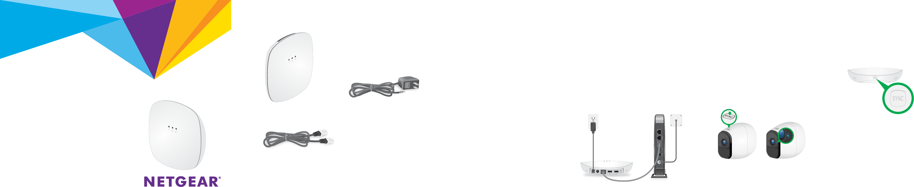
Package Contents
Base station Power cord
(localized to the region)
Note: For the ceiling and wall
installation kit, see the other
side of this document.
Ethernet cable
The Wire-Free IP Camera Base Station accepts WiFi streaming video data from
NETGEAR Wire-Free IP Cameras and delivers the video data to ONVIF-compliant
VMS platforms such as Milestone. The base station is compatible with NETGEAR
Wire-Free IP Cameras model VNC4030-111PAS. Each base station supports WiFi
streaming from up to four IP cameras.
You can mount the base station on a ceiling or wall, or install it on a flat surface.
For optimal antenna performance, we recommend mounting the base station on a
ceiling or installing it on a flat surface. For information about how to mount the base
station on the ceiling, see Ceiling-Mount the Base Station on the other side of this
document.
Step 1: Install the Base Station
1. Use an Ethernet cable to connect the base station to a router or switch.
2. Connect the power cord that
came in the package to the
base station and plug it in to an
electrical outlet.
3. Press the Power button on the
rear of the base station.
The Power LED and the Network
LED light solid green.
Step 2: Sync Your Cameras to the Base Station
1. Make sure that the rechargeable battery is installed in the camera and
the camera is powered on.
For information about how to install the camera battery, see the Wire-Free IP
Camera Quick Start Guide that came with the camera.
2. Place the camera 2-to-4 feet (60–120 cm) from the base station.
3. On the base station, press the SYNC button.
The Sync LED on the base station begins blinking
blue. This indicates that the base station is
attempting to pair with a camera.
4. On the camera, press the SYNC button.
The camera LED blinks blue. This indicates that the camera is attempting to pair
with the base station.
When the camera is paired to the base station, the base station Sync LED blinks
blue rapidly and then lights solid green.
5. Repeat Steps 1–4 to pair more cameras to the base station, if desired.
6. Move the cameras to the desired locations.
Step 3: Initial Setup
During initial setup, your computer or mobile device must be connected to the same
LAN as the base station. An Internet connection is not required.
1. Connect your computer or mobile device to the same LAN as the base
station.
If you are unable to connect to the same LAN using WiFi, use an Ethernet cable
to connect a computer to the same router or switch as the base station.
2. Launch a web browser.
3. In the address field of the browser, enter <??>
A login window displays.
4. Enter admin for the user name and enter the password.
The default password is password.
5. When prompted, create a new password.
You are prompted to select 60 hz or 50 hz for the flicker setting.
6. Either accept the 60 hz default setting, or select 50 hz.
The home page displays all cameras that are paired to the base station.
To change the camera names, use the Camera Settings menu for each camera.
To refresh the camera image and control the camera, tap or click the Snapshot
button for each camera.
For optimal performance, we recommend that you set up motion detection
sensitivity and a motion detection schedule, as described in the Wire-Free IP Camera
Base Station User Manual.
DRAFT
Model: VNB4000
May 2017
NETGEAR, Inc.
350 East Plumeria Drive
San Jose, CA 95134, USA
NETGEAR INTL LTD
Building 3, University Technology Centre
Curraheen Road, Cork, Ireland
Support
Thank you for purchasing this NETGEAR product. You can visit
www.netgear.com/support to register your product, get help, access the latest
downloads and user manuals, and join our community. We recommend that you use
only official NETGEAR support resources.
For the current EU Declaration of Conformity, visit
http://support.netgear.com/app/answers/detail/a_id/11621/.
For regulatory compliance information, visit
http://www.netgear.com/about/regulatory/.
See the regulatory compliance document before connecting the power supply.
© NETGEAR, Inc., NETGEAR and the NETGEAR Logo are trademarks of NETGEAR, Inc. Any non-NETGEAR
trademarks are used for reference purposes only.
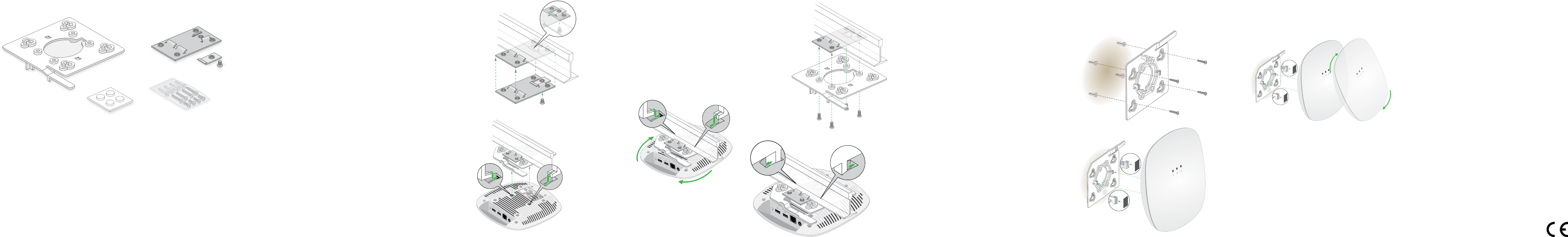
Ceiling and Wall Installation Kit
• Plastic bracket for either drop ceiling mounting or wall mounting. (1)
• Metal bracket for drop ceiling mounting. (2)
• One metal T-bar for drop ceiling mounting. (3)
• One lock screw to lock the T-bar for drop ceiling mounting. (4)
• Four short screws to attach the metal bracket for drop ceiling mounting. (5)
• Four tall screws to attach the plastic bracket for wall mounting. (6)
• Four anchors for the tall screws for wall mounting. (7)
• Four rubber feet for desk installation. (8)
4
5
6
7
8
12
3
BETA DOCUMENT
Drop Ceiling Installation
If you are mounting the base station on a hard ceiling
instead of a ceiling bar that is typical for a drop ceiling,
use the wall installation instructions.
1. Slide the T-bar partially into the metal bracket
and attach the metal bracket to the ceiling bar.
Then push the T-bar over the ceiling bar and use the
lock screw to lock the metal bracket into place.
2. Making sure that the two protruding
hooks on the plastic bracket are facing
down, place the plastic bracket against
the metal bracket and align the four inner
holes of the plastic bracket with the four
holes of the metal bracket.
Then insert the four short screws and secure
the plastic bracket onto the metal bracket.
1
2
3. Hold the base station upside down, with
the bottom facing the plastic bracket that
is attached to the metal bracket, and align
the two rectangular holes in the bottom of
the access point with the protruding hooks
on the plastic bracket.
4. Push the hooks into the holes and turn the
access point to secure it onto the plastic
bracket.
3
4
Wall Installation
1. Place the plastic bracket on the wall where you want to mount the base
station.
2. Mark the wall where the four outer
mounting holes are.
3. Using the wall anchors and tall
screws, attach the mounting bracket
to the wall.
4. Align the two rectangular holes in
the bottom of the access point with
the protruding hooks on the plastic
bracket.
Result
5. Push the hooks into the holes and turn the access point to secure it onto
the plastic bracket.
Desk Installation
For desk installation, attach the four round rubber feet to the locations marked by
the gray circles on the bottom of the access point.
DRAFT
Federal Communication Commission Interference Statement
This device complies with Part 15 of the FCC Rules. Operation is subject to
the following two conditions: (1) This device may not cause harmful
interference, and (2) this device must accept any interference received,
including interference that may cause undesired operation.
This equipment has been tested and found to comply with the limits for a
Class B digital device, pursuant to Part 15 of the FCC Rules. These limits
are designed to provide reasonable protection against harmful interference in a
residential installation. This equipment generates, uses and can radiate radio
frequency energy and, if not installed and used in accordance with the
instructions, may cause harmful interference to radio communications.
However, there is no guarantee that interference will not occur in a particular
installation. If this equipment does cause harmful interference to radio or
television reception, which can be determined by turning the equipment off
and on, the user is encouraged to try to correct the interference by one of the
following measures:
- Reorient or relocate the receiving antenna.
- Increase the separation between the equipment and receiver.
- Connect the equipment into an outlet on a circuit different from that
to which the receiver is connected.
- Consult the dealer or an experienced radio/TV technician for help.
FCC Caution: Any changes or modifications not expressly approved by the
party responsible for compliance could void the user's authority to operate this
equipment.
This transmitter must not be co-located or operating in conjunction with any
other antenna or transmitter.
Radiation Exposure Statement:
This equipment complies with FCC radiation exposure limits set forth for an
uncontrolled environment. This equipment should be installed and operated
with minimum distance 20cm between the radiator & your body.
Industry Canada statement:
This device complies with ISED’s licence-exempt RSSs. Operation is subject to the
following two conditions: (1) This device may not cause harmful interference, and (2)
this device must accept any interference received, including interference that may
cause undesired operation.
Le présent appareil est conforme aux CNR d’ ISED applicables aux appareils radio
exempts de licence. L’exploitation est autorisée aux deux conditions suivantes : (1) le
dispositif ne doit pas produire de brouillage préjudiciable, et (2) ce dispositif doit
accepter tout brouillage reçu, y compris un brouillage susceptible de provoquer un
fonctionnement indésirable.
Radiation Exposure Statement:
This equipment complies with ISED radiation exposure limits set forth for an
uncontrolled environment. This equipment should be installed and operated with
minimum distance 20cm between the radiator & your body.
Déclaration d'exposition aux radiations:
Cet équipement est conforme aux limites d'exposition aux rayonnements ISED
établies pour un environnement non contrôlé. Cet équipement doit être installé et
utilisé avec un minimum de 20 cm de distance entre la source de rayonnement et votre
corps.