Netgear orporated ANT24BX Wireless LAN System with Amplifier User Manual NETGEAR ME102 QCard
Netgear Incorporated Wireless LAN System with Amplifier NETGEAR ME102 QCard
UserManual.wiki
>
Netgear orporated
>
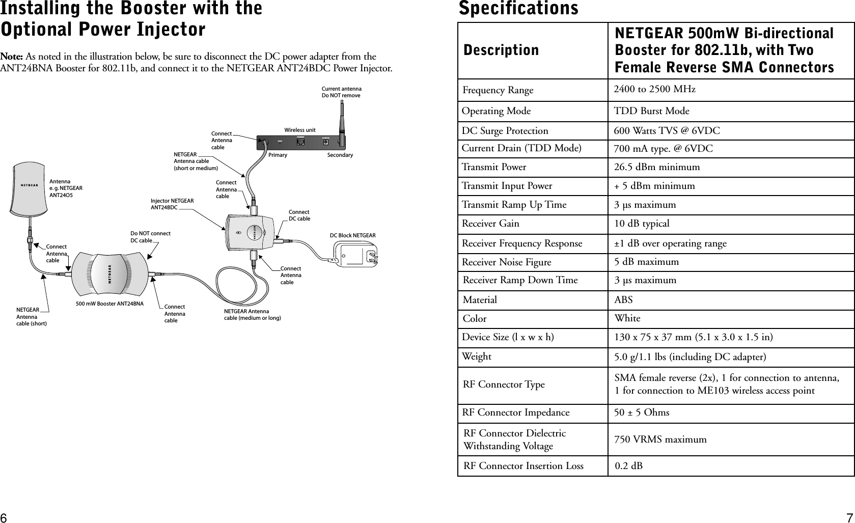
ANT24BX User Manual
Users Manual Revised
Navigation menu
Upload a User Manual
Namespaces
Wiki Guide
HTML
PDF
Info
Views
User Manual
Discussion / Help
Navigation