Netgear orporated CG814WB WIRELESS CABLE MODEM GATEWAY User Manual CG814W
Netgear Incorporated WIRELESS CABLE MODEM GATEWAY CG814W
USERS MANUAL

SM-CG814WNA-0
January 2003
NETGEAR, Inc.
4500 Great America Parkway
Santa Clara, CA 95054 USA
Phone 1-888-NETGEAR
Reference Manual for the
Model CG814W Wireless
Cable Modem Gateway

ii
© 2002 by NETGEAR, Inc. All rights reserved.
Trademarks
NETGEAR is a trademark of Netgear, Inc.
Microsoft, Windows, and Windows NT are registered trademarks of Microsoft Corporation.
Other brand and product names are registered trademarks or trademarks of their respective holders.
Statement of Conditions
In the interest of improving internal design, operational function, and/or reliability, NETGEAR reserves the right to
make changes to the products described in this document without notice.
NETGEAR does not assume any liability that may occur due to the use or application of the product(s) or circuit
layout(s) described herein.
Federal Communications Commission (FCC) Compliance Notice: Radio Frequency Notice
This equipment has been tested and found to comply with the limits for a Class B digital device, pursuant to
part 15 of the FCC Rules. These limits are designed to provide reasonable protection against harmful interference in a
residential installation. This equipment generates, uses, and can radiate radio frequency energy and, if not installed and
used in accordance with the instructions, may cause harmful interference to radio communications. However, there is no
guarantee that interference will not occur in a particular installation. If this equipment does cause harmful interference to
radio or television reception, which can be determined by turning the equipment off and on, the user is encouraged to try
to correct the interference by one or more of the following measures:
• Reorient or relocate the receiving antenna.
• Increase the separation between the equipment and receiver.
• Connect the equipment into an outlet on a circuit different from that to which the receiver is connected.
• Consult the dealer or an experienced radio/TV technician for help.
EN 55 022 Declaration of Conformance
This is to certify that the CG814W Wireless Cable Modem Gateway is shielded against the generation of radio
interference in accordance with the application of Council Directive 89/336/EEC, Article 4a. Conformity is declared by
the application of EN 55 022 Class B (CISPR 22).

iii
Bestätigung des Herstellers/Importeurs
Es wird hiermit bestätigt, daß das CG814W Wireless Cable Modem Gateway gemäß der im BMPT-AmtsblVfg 243/1991
und Vfg 46/1992 aufgeführten Bestimmungen entstört ist. Das vorschriftsmäßige Betreiben einiger Geräte (z.B.
Testsender) kann jedoch gewissen Beschränkungen unterliegen. Lesen Sie dazu bitte die Anmerkungen in der
Betriebsanleitung.
Das Bundesamt für Zulassungen in der Telekommunikation wurde davon unterrichtet, daß dieses Gerät auf den Markt
gebracht wurde und es ist berechtigt, die Serie auf die Erfüllung der Vorschriften hin zu überprüfen.
Certificate of the Manufacturer/Importer
It is hereby certified that the CG814W Wireless Cable Modem Gateway has been suppressed in accordance with the
conditions set out in the BMPT-AmtsblVfg 243/1991 and Vfg 46/1992. The operation of some equipment (for example,
test transmitters) in accordance with the regulations may, however, be subject to certain restrictions. Please refer to the
notes in the operating instructions.
Federal Office for Telecommunications Approvals has been notified of the placing of this equipment on the market
and has been granted the right to test the series for compliance with the regulations.
Voluntary Control Council for Interference (VCCI) Statement
This equipment is in the second category (information equipment to be used in a residential area or an adjacent area
thereto) and conforms to the standards set by the Voluntary Control Council for Interference by Data Processing
Equipment and Electronic Office Machines aimed at preventing radio interference in such residential areas.
When used near a radio or TV receiver, it may become the cause of radio interference.
Read instructions for correct handling.
Technical Support
Thank you for choosing Time Warner Cable "Wireless Road Runner" Service and Netgear product(s). Please register
online and take advantage of the technical support resources such as Netgear online knowledge base. Technical support
is available twenty-four hours a day, seven days a week; please call your local Time Warner Cable office.

iv

Contents v
Contents
About This Manual
Chapter 1
Introduction ..........................................................................................................................1-1
About the CG814W Gateway .........................................................................................1-1
Key Features ..................................................................................................................1-1
Built-in Cable Modem ...............................................................................................1-1
A Powerful, True Firewall .........................................................................................1-2
Content Filtering .......................................................................................................1-2
802.11b Standards-based Wireless Networking ......................................................1-2
Configurable Auto Uplink™ Ethernet Connection ....................................................1-3
USB Port ..................................................................................................................1-3
Protocol Support ......................................................................................................1-3
Easy Installation and Management ..........................................................................1-4
What’s in the Box? ..........................................................................................................1-5
The Gateway’s Front Panel ......................................................................................1-5
The Gateway’s Rear Panel ......................................................................................1-7
Chapter 2
Connecting the Gateway to the Internet ............................................................................2-1
What You Will Need Before You Begin ...........................................................................2-1
Hardware Requirements ..........................................................................................2-1
LAN Configuration Requirements ............................................................................2-1
Internet Configuration Requirements .......................................................................2-2
Where Do I Get the Internet Configuration Parameters? .........................................2-2
Record Your Internet Connection Information ..........................................................2-3
Connecting the CG814W Gateway ................................................................................2-4
Chapter 3
Wireless Configuration........................................................................................................3-1
Considerations For A Wireless Network .........................................................................3-1
Implement Appropriate Security ...............................................................................3-1

vi Contents
Observe Placement and Range Guidelines .............................................................3-2
Configuring Wireless Settings ........................................................................................3-3
Wireless Network Settings .......................................................................................3-3
Restricting Wireless Access by MAC Address .........................................................3-4
Configuring Wired Equivalent Privacy (WEP) ....................................................3-6
Chapter 4
Protecting Your Network .....................................................................................................4-1
Protecting Access to Your CG814W Gateway ................................................................4-1
Blocking Keywords, Sites, and Services ........................................................................4-2
Using Port Blocking ........................................................................................................4-4
Port Forwarding ..............................................................................................................4-6
Using Port Triggering ......................................................................................................4-8
Setting Up A Default DMZ Host ....................................................................................4-10
Respond to Ping on Internet WAN Port .................................................................4-10
Chapter 5
Managing Your Network ......................................................................................................5-1
Network Status Information ............................................................................................5-1
Viewing Gateway Status ..........................................................................................5-1
Connection Status ....................................................................................................5-3
Current System Time .........................................................................................5-3
Configuring LAN IP Settings ...........................................................................................5-4
LAN IP Setup ..................................................................................................................5-4
Using the Gateway as a DHCP Server ....................................................................5-5
DHCP Client Lease Info ....................................................................................5-6
Viewing and Emailing Logged Information .....................................................................5-7
Enabling Logs Event E-mail Notification ..................................................................5-7
Erasing Configuration .....................................................................................................5-8
Running Diagnostic Utilities ............................................................................................5-8
Chapter 6
Troubleshooting...................................................................................................................6-1
Basic Functions ..............................................................................................................6-1
Power LED Not On ...................................................................................................6-2
Test LED Stays On ...................................................................................................6-2
Local Link LEDs Not On ...........................................................................................6-2
Cable Link LED Not On ............................................................................................6-3

Contents vii
Troubleshooting the Web Configuration Interface ..........................................................6-3
Troubleshooting the ISP Connection ..............................................................................6-4
Troubleshooting a TCP/IP Network Using a Ping Utility .................................................6-4
Testing the LAN Path to Your Gateway ....................................................................6-4
Testing the Path from Your PC to a Remote Device ................................................6-5
Appendix A
Technical Specifications .................................................................................................... A-1
Appendix B
Networks, Routing, and Firewall Basics........................................................................... B-1
Related Publications ...................................................................................................... B-1
Basic Router Concepts .................................................................................................. B-1
What is a Router? ................................................................................................... B-2
Routing Information Protocol ................................................................................... B-2
IP Addresses and the Internet ................................................................................. B-2
Netmask .................................................................................................................. B-4
Subnet Addressing .................................................................................................. B-5
Private IP Addresses ............................................................................................... B-7
Single IP Address Operation Using NAT ................................................................. B-8
MAC Addresses and Address Resolution Protocol ................................................. B-9
Related Documents ................................................................................................. B-9
Domain Name Server ............................................................................................ B-10
IP Configuration by DHCP .................................................................................... B-10
Internet Security and Firewalls .................................................................................... B-10
What is a Firewall? .................................................................................................B-11
Stateful Packet Inspection ......................................................................................B-11
Denial of Service Attack .........................................................................................B-11
Wireless Networking Overview .................................................................................... B-12
Infrastructure Mode ............................................................................................... B-12
Ad Hoc Mode (Peer-to-Peer Workgroup) .............................................................. B-12
Network Name: Extended Service Set Identification (ESSID) .............................. B-13
Authentication and WEP .............................................................................................. B-13
802.11b Authentication .......................................................................................... B-13
Open System Authentication ................................................................................. B-14
Shared Key Authentication .................................................................................... B-15
Overview of WEP Parameters .............................................................................. B-16

viii Contents
Key Size ................................................................................................................ B-16
WEP Configuration Options .................................................................................. B-17
Wireless Channels ....................................................................................................... B-18
Ethernet Cabling .......................................................................................................... B-20
Uplink Switches and Crossover Cables ................................................................ B-20
Cable Quality ......................................................................................................... B-21
Appendix C
Preparing Your Network ..................................................................................................... C-1
Preparing Your Computers for TCP/IP Networking ....................................................... C-1
Configuring Windows 95, 98, and Me for TCP/IP Networking ....................................... C-2
Install or Verify Windows Networking Components ................................................. C-2
Enabling DHCP in Windows 95B, 98, and Me ........................................................ C-4
Selecting Windows’ Internet Access Method .......................................................... C-6
Verifying TCP/IP Properties .................................................................................... C-6
Configuring Windows NT4, 2000 or XP for IP Networking ............................................ C-7
Install or Verify Windows Networking Components ................................................. C-7
DHCP Configuration of TCP/IP in Windows XP, 2000, or NT4 ............................... C-8
DHCP Configuration of TCP/IP in Windows XP ..................................................... C-8
DHCP Configuration of TCP/IP in Windows 2000 ................................................ C-11
DHCP Configuration of TCP/IP in Windows NT4 .................................................. C-14
Verifying TCP/IP Properties for Windows XP, 2000, and NT4 .............................. C-16
Configuring the Macintosh for TCP/IP Networking ...................................................... C-17
MacOS 8.6 or 9.x .................................................................................................. C-17
MacOS X ............................................................................................................... C-18
Verifying TCP/IP Properties for Macintosh Computers ......................................... C-18
Verifying the Readiness of Your Internet Account ....................................................... C-19
Are Login Protocols Used? ................................................................................... C-19
What Is Your Configuration Information? .............................................................. C-19
Obtaining ISP Configuration Information for Windows Computers ....................... C-20
Obtaining ISP Configuration Information for Macintosh Computers ..................... C-21
Restarting the Network ................................................................................................ C-22
Glossary..............................................................................................................................G-1

Reference Manual for the Model CG814W Wireless Cable Modem Gateway
About This Manual ix
About This Manual
Thank your for purchasing the NETGEAR™ CG814W Wireless Cable Modem Gateway.
This manual describes the features of the gateway and provides installation and configuration
instructions.
Audience
This reference manual assumes that the reader has basic to intermediate computer and Internet
skills. However, basic computer network, Internet, firewall, and PC networking technologies
tutorial information is provided in the Appendices.
Typographical Conventions
This guide uses the following typographical conventions:
italics Media titles, UNIX files, commands, URLs, and directory names.
bold times roman User input
Internet Protocol (IP) First time an abbreviated term is used.
courier font Screen text, user-typed command-line entries.
[Enter] Named keys in text are shown enclosed in square brackets. The notation
[Enter] is used for the Enter key and the Return key.
[Ctrl]+C Two or more keys that must be pressed simultaneously are shown in text
linked with a plus (+) sign.
ALL CAPS DOS file and directory names.
Reference Manual for the Model CG814W Wireless Cable Modem Gateway
xAbout This Manual
Special Message Formats
This guide uses the following formats to highlight special messages:
Technical Support
For help with any technical issues, contact Customer Support at 1-888-NETGEAR, or visit us on
the Web at www.NETGEAR.com. The NETGEAR Web site includes an extensive knowledge
base, answers to frequently asked questions, and a means for submitting technical questions
online.
Note: This format is used to highlight information of importance or special interest.
Warning: This format is used to highlight information about the possibility of injury or
equipment damage.
Danger: This format is used to alert you that there is the potential for incurring an
electrical shock if you mishandle the equipment.

Reference Manual for the Model CG814W Wireless Cable Modem Gateway
Introduction 1-1
Chapter 1
Introduction
This chapter describes the features of the NETGEAR CG814W Wireless Cable Modem Gateway.
About the CG814W Gateway
The NETGEAR CG814W Wireless Cable Modem Gateway connects directly to the wide area
network (WAN) using its built-in cable modem. It has multiple options to connect to your local
area network (LAN), including a 4-port 10/100 Mbps Ethernet switch, a USB port and an 802.11b
wireless Access Point.
The CG814W Gateway is a complete security solution that protects your network from attacks and
intrusions. Unlike simple Internet sharing routers that rely on Network Address Translation (NAT)
for security, the CG814W Gateway uses Stateful Packet Inspection for Denial of Service (DoS)
attack protection and intrusion detection. The CG814W Gateway provides highly reliable Internet
access for up to 253 users.
Key Features
The CG814W Gateway offers the following features.
Built-in Cable Modem
The CG814W Gateway connects directly the WAN using an integrated cable modem. The modem
is DOCSIS 1.0 compliant and upgradable to DOCSIS 1.1, guaranteeing that it will work with your
local cable service provider.

Reference Manual for the Model CG814W Wireless Cable Modem Gateway
1-2 Introduction
A Powerful, True Firewall
Unlike simple Internet sharing NAT routers, the CG814W Gateway is a true firewall, using stateful
packet inspection to defend against hacker attacks. Its firewall features include:
• Denial of Service (DoS) protection
Automatically detects and thwarts Denial of Service (DoS) attacks such as Ping of Death,
SYN Flood, LAND Attack and IP Spoofing.
• Configurable Port Forwarding, Port Blocking, Port Triggering and DMZ provide enough
flexibility for most applications.
• Blocks access from your LAN to Internet locations or services that you specify as off-limits.
• Logs security incidents
The CG814W Gateway will log security events such as blocked incoming traffic, port scans,
attacks, and administrator logins. You can configure the gateway to email the log to you
whenever a significant event occurs.
Content Filtering
With its content filtering feature, the CG814W Gateway prevents objectionable content from
reaching your PCs. The gateway allows you to control access to Internet content by screening for
keywords within Web addresses. You can configure the gateway to log and report attempts to
access objectionable Internet sites.
802.11b Standards-based Wireless Networking
The CG814W Gateway includes an 802.11b-compliant wireless access point, providing
continuous, high-speed 11 Mbps access between your wireless and Ethernet devices. The access
point provides:
• 802.11b Standards-based wireless networking at up to 11 Mbps
• 64-bit and 128-bit WEP encryption security
• WEP keys can be generated manually or by passphrase
• Wireless access can be restricted by MAC address.

Reference Manual for the Model CG814W Wireless Cable Modem Gateway
Introduction 1-3
Configurable Auto Uplink™ Ethernet Connection
With its internal 4-port 10/100 switch, the CG814W Gateway can connect to either a 10 Mbps
standard Ethernet network or a 100 Mbps Fast Ethernet network. Both the local LAN and the
Internet WAN interfaces are autosensing and capable of full-duplex or half-duplex operation.
The gateway incorporates Auto UplinkTM technology. Each LOCAL Ethernet port will
automatically sense whether the Ethernet cable plugged into the port should have a ‘normal’
connection such as to a PC or an ‘uplink’ connection such as to a switch or hub. That port will then
configure itself to the correct configuration. This feature also eliminates the need to worry about
crossover cables, as Auto Uplink will accommodate either type of cable to make the right
connection.
USB Port
A USB connection for your computer eliminates the need for installing an Ethernet card.
Protocol Support
The CG814W Gateway supports the Transmission Control Protocol/Internet Protocol (TCP/IP).
Appendix B, "Networks, Routing, and Firewall Basics" provides further information on TCP/IP.
• IP Address Sharing by NAT
The CG814W Gateway allows several networked PCs to share an Internet account using only
a single IP address, which may be statically or dynamically assigned by your Internet service
provider (ISP). This technique, known as Network Address Translation (NAT), allows the use
of an inexpensive single-user ISP account.
• Automatic Configuration of Attached PCs by DHCP
The CG814W Gateway dynamically assigns network configuration information, including
IP, gateway, and domain name server (DNS) addresses, to attached PCs on the LAN using the
Dynamic Host Configuration Protocol (DHCP). This feature greatly simplifies configuration
of PCs on your local network.
• DNS Relay
When DHCP is enabled and no DNS addresses are specified, the gateway provides its own
address as a DNS server to the attached PCs. The gateway obtains actual DNS addresses from
the ISP during connection setup and forwards DNS requests from the LAN.

Reference Manual for the Model CG814W Wireless Cable Modem Gateway
1-4 Introduction
Easy Installation and Management
You can install, configure, and operate the CG814W Gateway within minutes after connecting it to
the network. The following features simplify installation and management tasks:
• Browser-based management
Browser-based configuration allows you to easily configure your gateway from almost any
type of personal computer, such as Windows, Macintosh, or Linux. A user-friendly Setup
Wizard is provided and online help documentation is built into the browser-based Web
Management Interface.
• Diagnostic functions
The gateway incorporates built-in diagnostic functions such as Ping, DNS lookup, and remote
reboot. These functions allow you to test Internet connectivity and reboot the gateway. You
can use these diagnostic functions directly from the CG814W Gateway when your are connect
on the LAN or when you are connected over the Internet via the remote management function.
• Visual monitoring
The gateway’s front panel LEDs provide an easy way to monitor its status and activity.
Reference Manual for the Model CG814W Wireless Cable Modem Gateway
Introduction 1-5
What’s in the Box?
The product package should contain the following items:
• CG814W Wireless Cable Modem Gateway
•AC power adapter
• Category 5 (CAT5) Ethernet cable
• USB cable
•Resource CD, including:
— This manual
— Application Notes, Tools, and other helpful information
If any of the parts are incorrect, missing, or damaged, contact your NETGEAR dealer. Keep the
carton, including the original packing materials, in case you need to return the product for repair.
The Gateway’s Front Panel
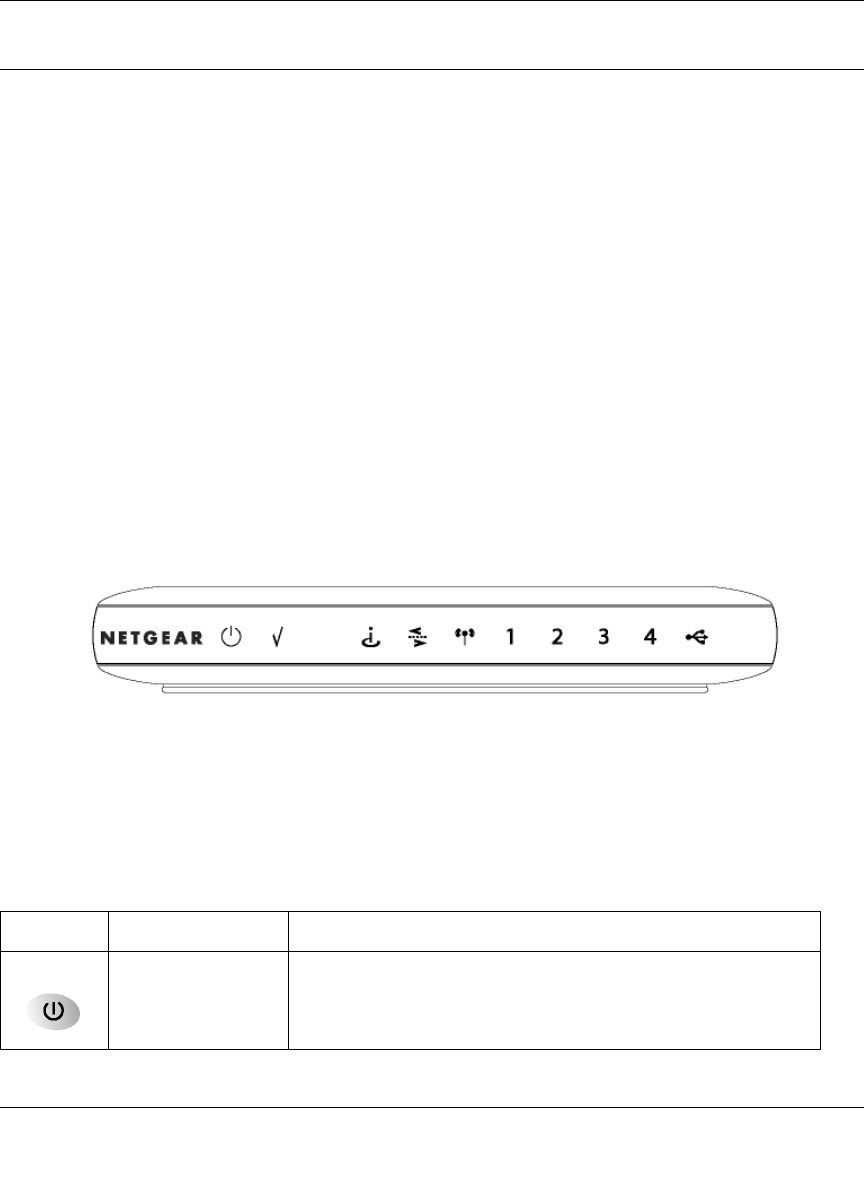
The front panel of the CG814W Gateway (Figure 1-1) contains status LEDs.
Figure 1-1: CG814W Gateway Front Panel
You can use some of the LEDs to verify connections. Table 1-1 lists and describes each LED on
the front panel of the CG814W Gateway. These LEDs are green when lit.
Table 1-1. LED Descriptions
Label Activity Description
Power On
Off Power is supplied to the gateway.
Power is not supplied to the gateway.
Reference Manual for the Model CG814W Wireless Cable Modem Gateway
1-6 Introduction
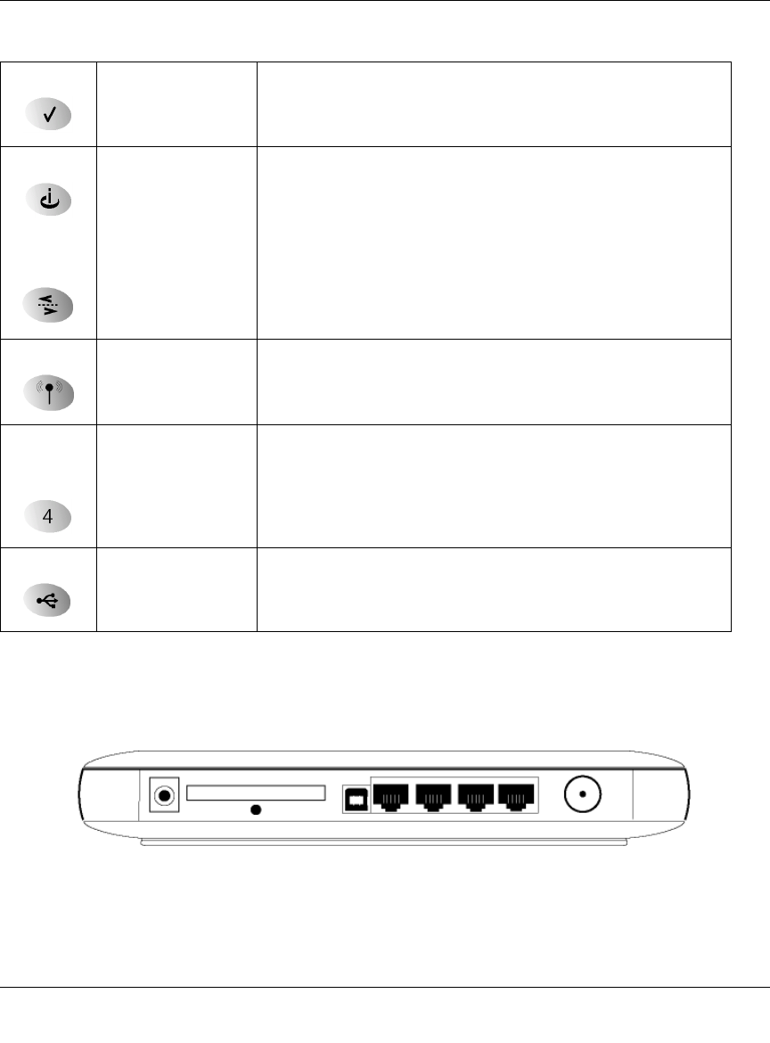
The Gateway’s Rear Panel
The rear panel of the CG814W Gateway (Figure 1-2) contains the connections identified below.
Figure 1-2: CG814W Gateway Rear Panel
Viewed from left to right, the rear panel contains the following elements:
Test On
Off A system failure has occurred. Reboot the gateway.
Normal operation.
Cable Link On (Green)
Off
Configuration of the cable interface by your cable service provider
is complete.
Configuration of the cable interface is still in progress.
Cable
Traffic On
Off Data is being transmitted or received on the cable interface.
The cable interface is idle.
Wireless On
Blink Indicates that the wireless Access Point is operating normally.
Data is being transmitted or received on the wireless interface.
Local
(Local Area
Network)
On (Green)
Blink (Green)
On (Yellow)
Blink (Yellow)
Off
The Local port has detected link with a 100 Mbps device.
Data is being transmitted or received at 100 Mbps.
The Local port has detected link with a 10 Mbps device.
Data is being transmitted or received at 10 Mbps.
No link is detected on this port.
USB On (Green)
Blink (Green)
Off
The Local port has detected link with a USB device.
Data is being transmitted or received through USB.
No link is detected on the USB port.
Table 1-1. LED Descriptions

Reference Manual for the Model CG814W Wireless Cable Modem Gateway
Introduction 1-7
• AC power adapter input
• 802.11b Wireless antenna
• Factory Default Reset push button
• USB port for connecting the gateway to a local computer
• Four Ethernet RJ-45 ports for connecting the gateway to local computers
• Coaxial F-type connector for connecting the gateway to your cable service provider

Reference Manual for the Model CG814W Wireless Cable Modem Gateway
1-8 Introduction

Reference Manual for the Model CG814W Wireless Cable Modem Gateway
Connecting the Gateway to the Internet 2-1
Chapter 2
Connecting the Gateway to the Internet
This chapter describes how to set up the CG814W Gateway on your Local Area Network (LAN),
connect to the Internet and perform basic configuration.
What You Will Need Before You Begin
You need to prepare these three things before you can connect your gateway to the Internet:
1. A computer properly connected to the gateway as explained below.
2. Active Data Over Cable Internet service provided by cable modem account.
3. The Internet Service Provider (ISP) configuration information for your cable modem account.
Hardware Requirements
The CG814W Gateway connects to your LAN using either its twisted-pair Ethernet, USB or
802.11b wireless port.
To use the CG814W Gateway on your network, each computer must have either an installed
Ethernet Network Interface Card (NIC), USB Host port or 802.11b wireless adapter. If the
computer will connect to your network at 100 Mbps, you must use a Category 5 (CAT5) cable such
as the one provided with your gateway.
LAN Configuration Requirements
For the initial connection to the Internet and configuration of your gateway, you will need to
connect a computer to the gateway which is set to automatically get its TCP/IP configuration from
the gateway via DHCP.

Reference Manual for the Model CG814W Wireless Cable Modem Gateway
2-2 Connecting the Gateway to the Internet
Note: Please refer to Appendix C, "Preparing Your Network" for assistance with DHCP
configuration.
Internet Configuration Requirements
Depending on how your ISP set up your Internet account, you will need one or more of these
configuration parameters to connect your gateway to the Internet:
• Host and Domain Names
• ISP Domain Name Server (DNS) Addresses
• Fixed or Static IP Address
• MAC Address of the PC you used to first connect to the cable modem service
Where Do I Get the Internet Configuration Parameters?
If you already have cable Internet service and are replacing a cable modem, you may need these
parameters.
• CG814W Gateway Cable and Device MAC Address, that can be found on the bottom of your
gateway, or on the Basic Settings page.
• The MAC Address of the PC that you use to access the internet.
There are several ways you can gather the required Internet connection information.
• Your ISP should have provided you with all the information needed to connect to the Internet.
If you cannot locate this information, you can ask your ISP to provide it or you can try one of
the options below.
• If you have a computer already connected using the active Internet access account, you can
gather the configuration information from that computer.
• For Windows 95/98/ME, open the Network control panel, select the TCP/IP entry for the
Ethernet adapter, and click Properties.
• For Windows 2000/XP, open the Local Area Network Connection, select the TCP/IP entry
for the Ethernet adapter, and click Properties.
• For Macintosh computers, open the TCP/IP or Network control panel.
Once you locate your Internet configuration parameters, you may want to record them on the page
below.

Reference Manual for the Model CG814W Wireless Cable Modem Gateway
Connecting the Gateway to the Internet 2-3
Record Your Internet Connection Information
Print this page. Fill in the configuration parameters from your Internet Service Provider (ISP).
Host and Domain Names: Some ISPs use a specific host or domain name like CCA7324-A or
attbi. If you haven’t been given host or domain names, use the following examples as a guide:
• If your main e-mail account with your ISP is aaa@yyy.com, then use aaa as your host name.
Your ISP might call this your account, user, host, computer, or system name.
• If your ISP’s mail server is mail.xxx.yyy.com, then use xxx.yyy.com as the domain name.
ISP Host Name: _________________________ ISP Domain Name: _______________________
Fixed or Static IP Address: If you have a static IP address, record the following information. For
example, 169.254.141.148 could be a valid IP address.
Fixed or Static Internet IP Address: ______ . ______ . ______ . ______
Subnet Mask: ______ . ______ . ______ . ______
Gateway IP Address: ______ . ______ . ______ . ______
ISP DNS Server Addresses: If you were given DNS server addresses, fill in the following:
Primary DNS Server IP Address: ______ . ______ . ______ . ______
Secondary DNS Server IP Address: ______ . ______ . ______ . ______
MAC Addresses of CG814W Gateway and PC: If you have existing cable internet service and are
replacing your cable modem you may need to notify your cable service provider of the MAC
Address (often called Hardware Address) and/or Device Address of your CG814W Gateway. The
Device Address is the equivalent of a PC behind the cable modem, and can be “cloned”. Cloning
allows you to specify the MAC address of the packets the gateway sends to the internet. If you
clone the MAC Address of your PC you will not have to register the Device Address of your
gateway.
Cable Modem MAC (listed on the bottom of your gateway): ______________________________
Device MAC (listed on the bottom of your gateway): ____________________________________
PC MAC Address (listed on the Basic Settings page): ___________________________________
Reference Manual for the Model CG814W Wireless Cable Modem Gateway
2-4 Connecting the Gateway to the Internet
Connecting the CG814W Gateway
Before using your gateway, you need to do the following:
• Connect to your computer, using either Ethernet, USB or wireless.
• Connect the line from your cable service provider to the cable connector of the gateway.
• Connect the power adapter.
Your computer will attach to either the Ethernet, USB or wireless ports on the CG814W Gateway.
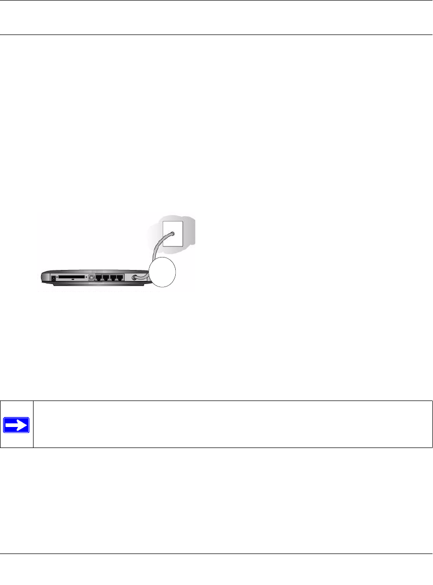
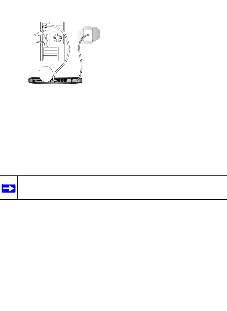
1. Connect the Gateway.
a. Turn off your computer.
b. Using the coaxial cable provided by your cable company, connect the CG814W Gateway
cable port (A) to your cable line splitter or outlet.
Figure 2-1: Connect the gateway to the cable network.
c. Connect the gateway to you computer.
— If you will connect with the Ethernet cable, follow the instructions below.
— If you will connect with the USB cable, skip to step d below.
Note: Set up the CG814W Gateway using either an Ethernet or USB connection to your
computer first, then configure the wireless settings. Detailed instructions on configuring
your wireless devices for TCP/IP networking are provided in the next chapter.
A
Reference Manual for the Model CG814W Wireless Cable Modem Gateway
Connecting the Gateway to the Internet 2-5
Connect the gateway to you computer using the Ethernet cable included in the box from
your CG814W Gateway’s LAN port (B) to the Ethernet adapter in your computer.
Figure 2-2: Connect a PC to the gateway
The CG814W Gateway incorporates Auto UplinkTM technology. Each LOCAL Ethernet
port will automatically sense whether the cable plugged into the port should have a
'normal' connection (e.g. connecting to a PC) or an 'uplink' connection (e.g. connecting to
a switch or hub). That port will then configure itself to the correct configuration. This
feature also eliminates the need to worry about crossover cables, as Auto Uplink will
accommodate either type of cable to make the right connection.
d. To connect your computer to the modem via USB involves installing the USB driver.Insert
the CD which came with your gateway into the CD drive of your computer.
Install the USB driver.
– Connect the USB cable to your modem and plug in the AC power for the gateway.
– Use the USB cable to connect your computer to the gateway.
Note: The USB connection option is only available for Windows PCs. Also, Windows
95 does not support USB without special operating system upgrades and patches.
CG i l C bl d G
B
Reference Manual for the Model CG814W Wireless Cable Modem Gateway
2-6 Connecting the Gateway to the Internet
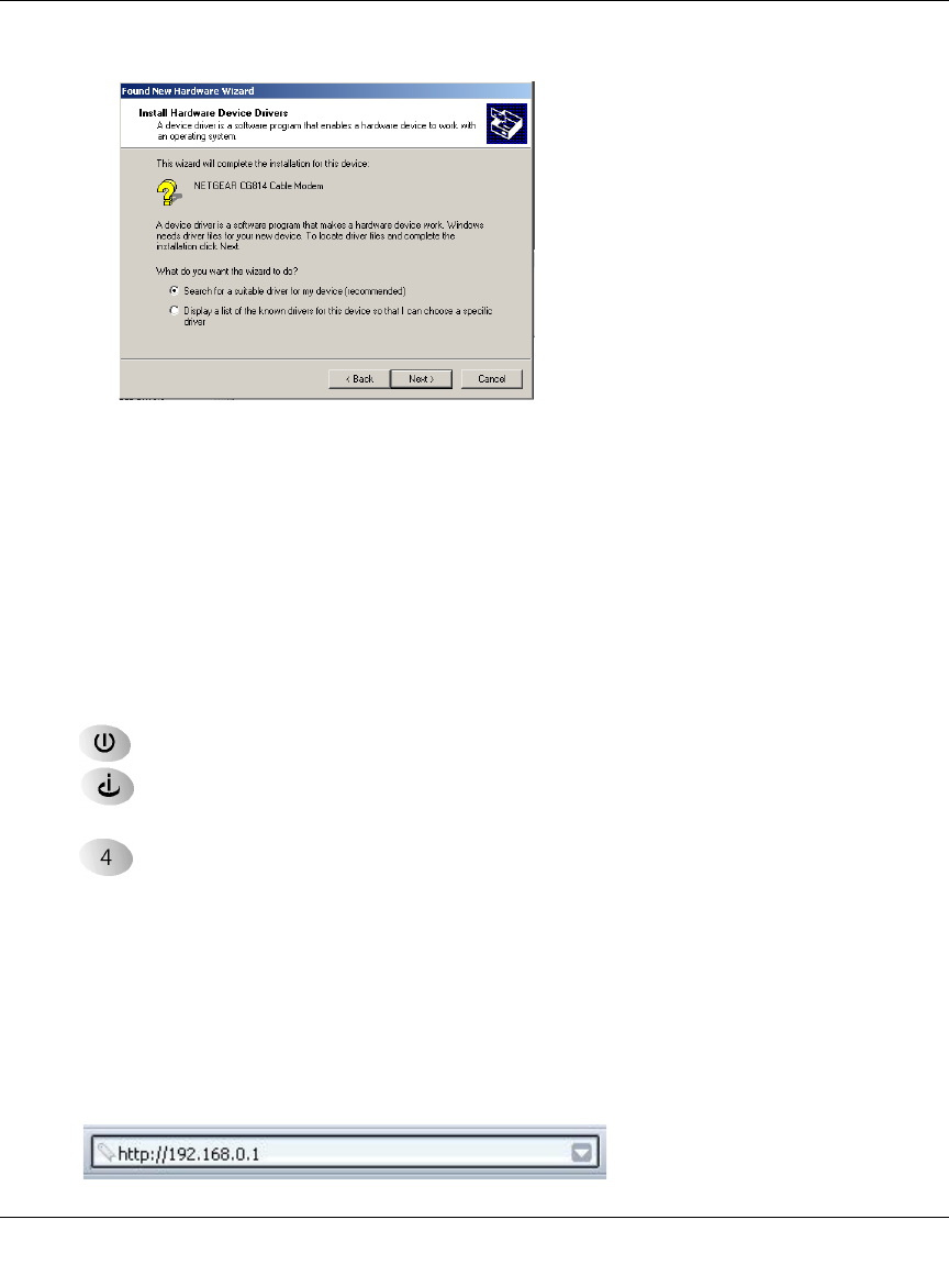
– The found new hardware Windows installation wizard will prompt you for the drivers.
Figure 2-3: Found New Hardware Wizard window
Browse to the CD and install the USB driver by clicking through the Windows wizard
prompts.
e. Plug in your CG814W Gateway and wait about 30 seconds for the lights to stop blinking.
f. Now, turn on your computer. If software usually logs you in to your Internet connection,
do not run that software or cancel it if it starts automatically.
g. Verify the following:
The power light is lit after turning on the gateway.
The cable link light is solid green, indicating a link has been established to the cable
network.
The local lights are lit for any connected computers.
2. Log in to the Gateway.
Note: To connect to the gateway, your computer needs to be configured to obtain an IP
address automatically via DHCP. For instructions on how to do this, please see Appendix C,
"Preparing Your Network".
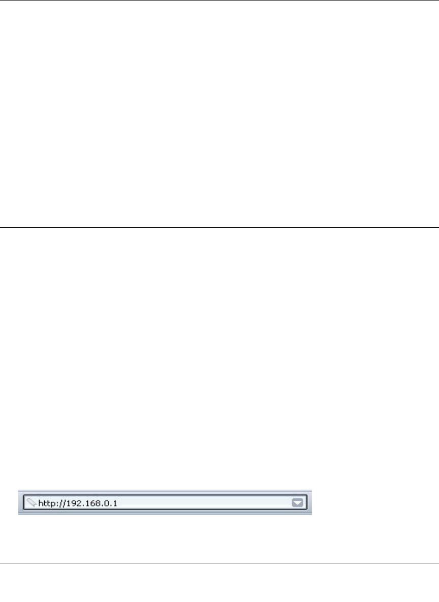
a. Using the computer you first used to access your cable modem Internet service, connect to
the gateway by typing http://192.168.0.1 in the address field of Internet Explorer or
Netscape® Navigator.
Reference Manual for the Model CG814W Wireless Cable Modem Gateway
Connecting the Gateway to the Internet 2-7
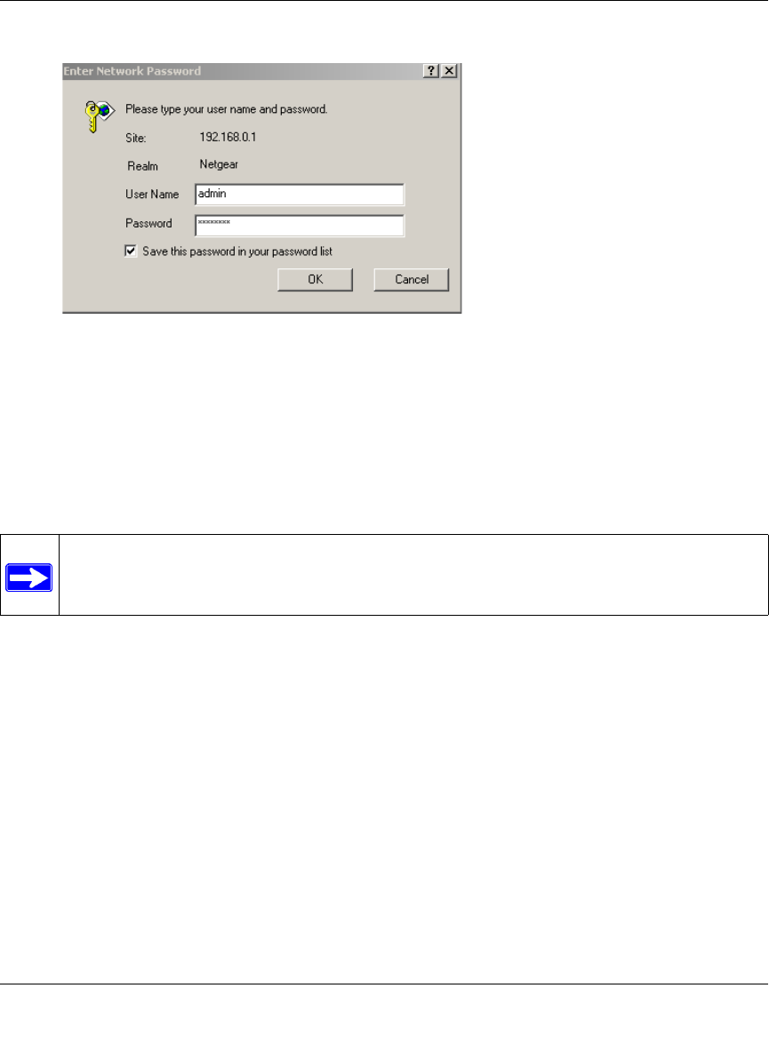
A login window opens as shown in Figure 2-4 below:
Figure 2-4: Login window
b. For security reasons, the gateway has its own user name and password. When prompted,
enter admin for the user name and password for the password, both in lower case letters.
c. After logging in, you will see the Basic Settings shown in Figure 2-5 below.
Note: If you were unable to connect to the gateway, please refer to “Basic Functions” on
page 6-1.
Reference Manual for the Model CG814W Wireless Cable Modem Gateway
2-8 Connecting the Gateway to the Internet
3. Connect to the Internet.
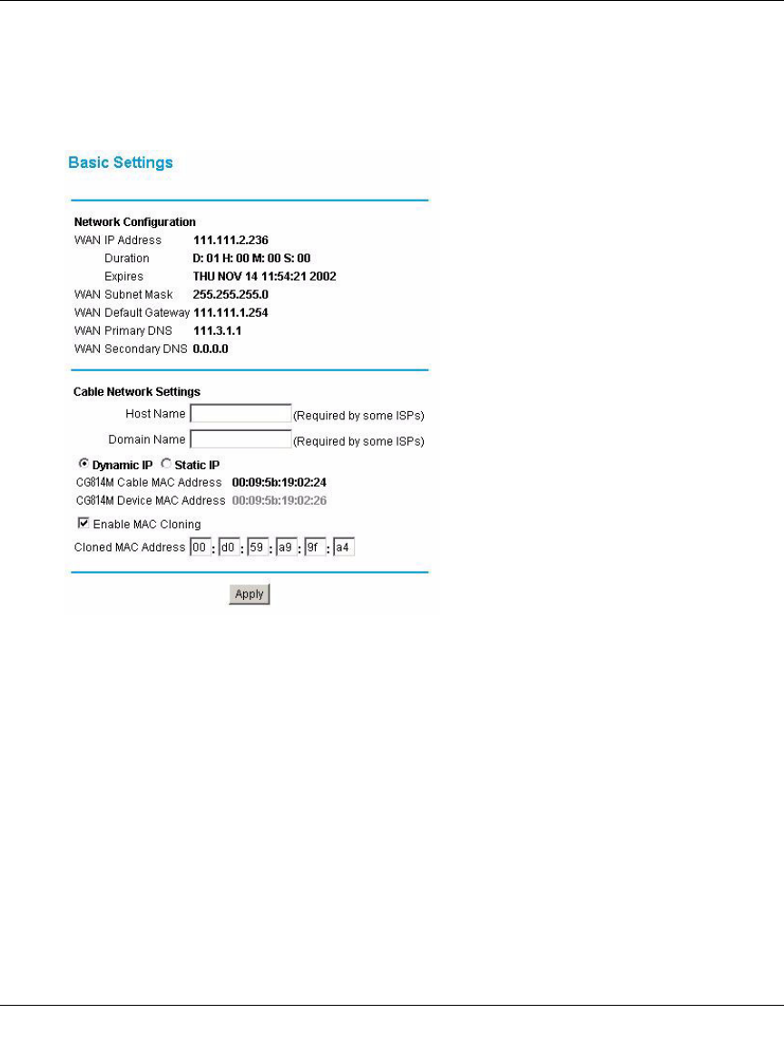
a. You are now connected to the gateway. Click the Basic Settings link on the upper left of
the main menu. You are now connected to the gateway’s Basic Settings page, shown
below.
Figure 2-5: Basic Settings page
You are ready to configure your gateway to connect to the Internet.
Unless your ISP assigns your configuration automatically via DHCP, you will need the
ISP configuration parameters you recorded in “Record Your Internet Connection
Information” on page 2-3.
b. Your current WAN IP address information is shown on this page.
If you have set your configuration for Dynamic IP, below, then an IP address information
shown here is an indication that you have successfully received an IP address from your
service provider.
If you have set your configuration to Static IP, below, then the IP address information you
entered will be shown here.

Reference Manual for the Model CG814W Wireless Cable Modem Gateway
Connecting the Gateway to the Internet 2-9
For Dynamic IP, the Duration and time of Expiration of the IP address are shown. The IP
address is renewed automatically using DHCP.
c. Enter your Host Name and Domain Name.
These parameters may be necessary to access your ISP’s services such as mail or news
servers.
If your ISP does not provide a Host and Domain name, you can use the following
example: If your main e-mail account with your ISP is aaa@yyy.com, then use aaa as
your host name and yyy.com as the domain name.
d. Select Dynamic or Static IP Address:
If your service provider assigns your IP address automatically through DHCP, select
“Dynamic IP”. If your service provider has assigned you a permanent, fixed (static) IP
address for your PC, select “Static IP”.
If you select Static IP, enter the IP address that your ISP assigned. Also enter the Static IP
Mask (also known as netmask), Gateway IP address and Domain Name Server (DNS)
Address.
– The Gateway is the ISP’s router to which your gateway will connect.
– A DNS server is a host on the Internet that translates Internet names (such as
www.netgear.com) to numeric IP addresses. Typically your ISP transfers the IP
address of one or two DNS servers to your gateway during login. If the ISP does not
transfer an address, you must obtain it from the ISP and enter it manually here. If you
enter an address here, you should reboot your PCs after configuring the gateway.
e. The CG814W Gateway Cable MAC address is for the built-in cable modem. The
CG814W Gateway Device MAC address is for the built-in router. MAC cloning lets you
substitute a different MAC address for the CG814W Gateway’s built-in router address.
Note: Some cable Internet companies will require you to notify them when you replace
the original cable modem or PC so that they can register the MAC address of one or both
of these devices.
• MAC cloning lets you substitute a different MAC address for the CG814W Gateway’s
built-in router address.
The first time you log in to the CG814W Gateway, it automatically fills in the Cloned
MAC Address with the MAC address from the PC which is logged in to the CG814W
Gateway.
• Click Apply to accept these settings.

Reference Manual for the Model CG814W Wireless Cable Modem Gateway
2-10 Connecting the Gateway to the Internet
Reference Manual for the Model CG814W Wireless Cable Modem Gateway
Wireless Configuration 3-1
Chapter 3
Wireless Configuration
This chapter describes how to configure the wireless features of your CG814W Wireless Cable
Modem Gateway.
Considerations For A Wireless Network
In planning your wireless network, you should consider the level of security required. You should
also select the physical placement of your gateway in order to maximize the network speed. For
further information on wireless networking, refer to “Wireless Networking Overview” in
Appendix B, "Networks, Routing, and Firewall Basics".”
Implement Appropriate Security
Unlike wired network data, your wireless data transmissions can extend beyond your walls and
can be received by anyone with a compatible adapter. For this reason, use the security features of
your wireless equipment. Restricting access by MAC address filtering adds an obstacle to
unwanted users joining your network. To hinder a determined eavesdropper, you should use one of
Wired Equivalent Privacy (WEP) data encryption options.
Note: If you are configuring the gateway from a wireless PC and you change the
gateway’s SSID, channel, or WEP settings, you will lose your wireless connection when
you click on Apply. You must then change the wireless settings of your PC to match the
gateway’s new settings.
Reference Manual for the Model CG814W Wireless Cable Modem Gateway
3-2 Wireless Configuration
Observe Placement and Range Guidelines
The operating distance or range of your wireless connection can vary significantly based on the
physical placement of the wireless gateway.
For best results, place your gateway:
• Near the center of the area in which your PCs will operate.
• In an elevated location such as a high shelf.
• Away from potential sources of interference, such as PCs, microwaves, and 2.4 GHz cordless
phones.
• Away from large metal surfaces.
Note: Failure to follow these guidelines can result in significant performance
degradation or inability to wirelessly connect to the router.
Reference Manual for the Model CG814W Wireless Cable Modem Gateway
Wireless Configuration 3-3
Configuring Wireless Settings
To configure the Wireless interface of your gateway, click on the Wireless Settings heading in the
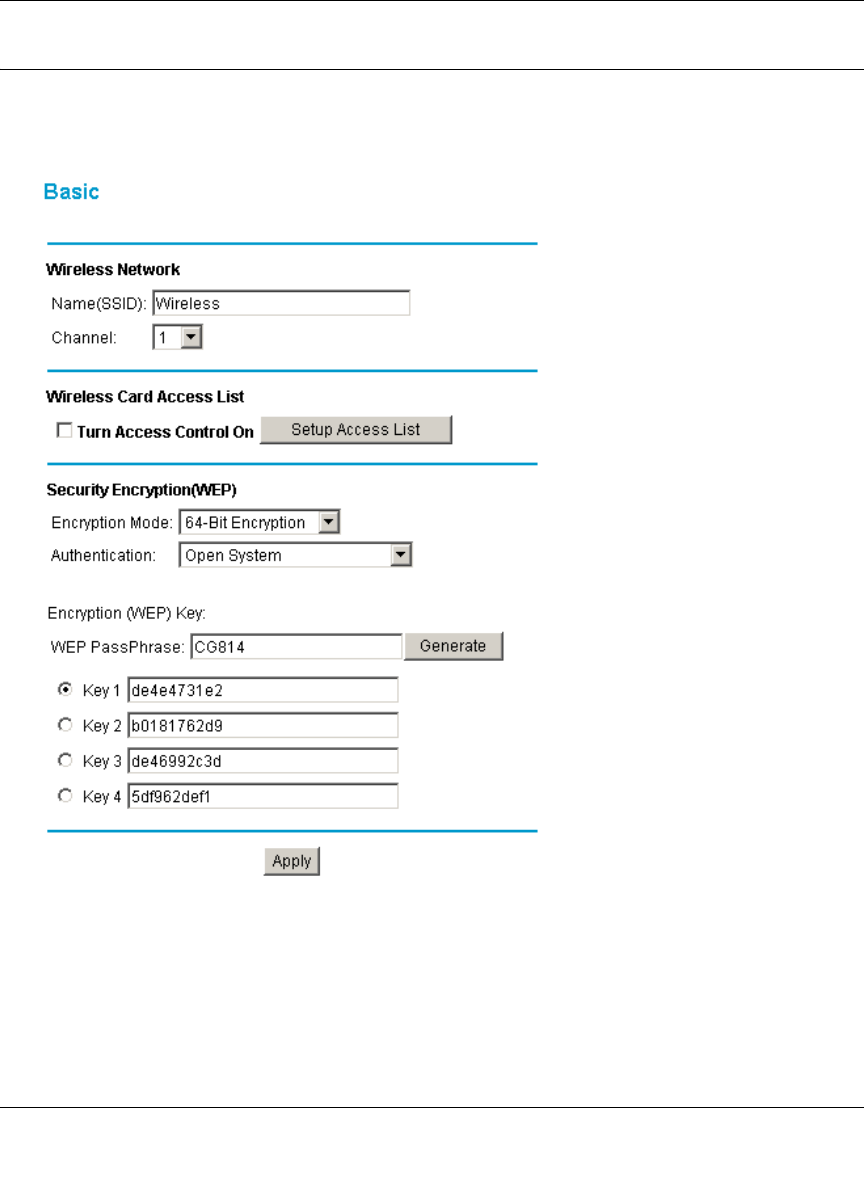
Setup section of the browser interface. The Wireless Settings menu will appear, as shown below:
Figure 3-1: Wireless Settings menu
Wireless Network Settings
In the Wireless Settings section are the following parameters:

Reference Manual for the Model CG814W Wireless Cable Modem Gateway
3-4 Wireless Configuration
• Name (SSID)
Enter a Service Set ID (SSID) value of up to 32 alphanumeric characters. The same SSID must
be assigned to all wireless devices in your network. The default SSID is Wireless, but
NETGEAR strongly recommends that you change your network’s SSID to a different value.
• Channel
This field determines which operating frequency will be used. It should not be necessary to
change the wireless channel unless you notice interference problems with another nearby
access point.
Restricting Wireless Access by MAC Address
By default, any wireless PC that is configured with the correct SSID will be allowed access to your
wireless network. For increased security, you can restrict access to the wireless network to only
allow specific PCs based on their MAC addresses.
Check the Turn Access Control On box to restrict access to you network to computers in the
Access Control List.
To access the Access List, click the Setup Access List button.
Note: If the Turn Access Control On is enabled and the Access Control List is
blank; then all wireless PCs will be unable to connect to your wireless network.
Reference Manual for the Model CG814W Wireless Cable Modem Gateway
Wireless Configuration 3-5
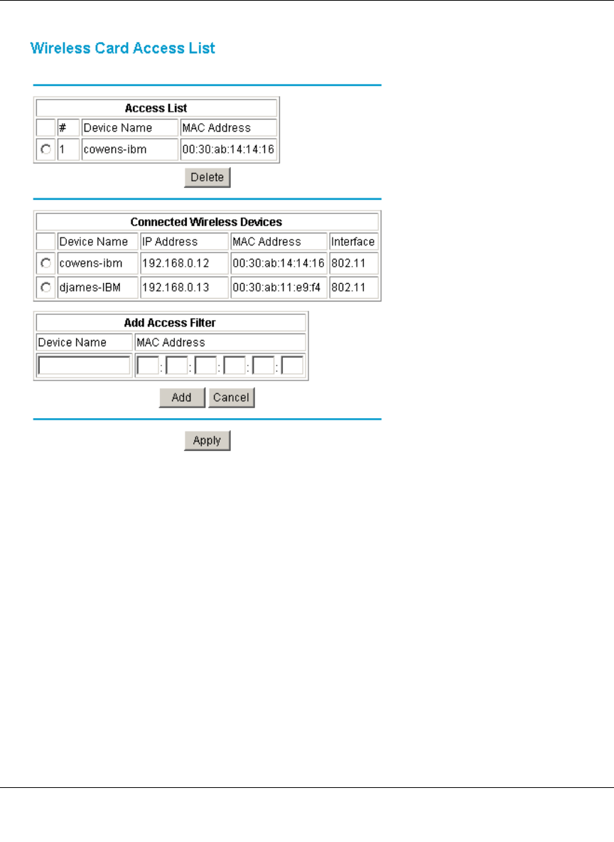
:
Figure 3-2: Wireless Access List menu
The Access List displays a list of MAC addresses that will be allowed to connect to the gateway.
These PCs must also have the correct SSID and WEP settings. You can add MAC addresses to the
Access List by either selecting form the list of Connected Wireless Devices, or by manual entering
MAC addresses
To restrict access based on MAC addresses:
1. For your convenience, this menu displays a list of currently Connected Wireless Devices and
their MAC addresses. Select a device from the list that you want to allow to access your
network.
2. If the desired PC does not appear in the list, you can manually enter the MAC address of the
authorized PC.
The MAC address is usually printed on the wireless card.

Reference Manual for the Model CG814W Wireless Cable Modem Gateway
3-6 Wireless Configuration
3. If no Device Name appears, you can type a descriptive name for the PC that you are adding.
4. Click Add.
5. When you have finished entering MAC addresses, click Apply to save the Access List and
return to the Wireless Settings menu.
To delete a MAC address from the table, click on it to select it, then click the Delete button.
Configuring Wired Equivalent Privacy (WEP)
In the Wireless Settings menu you can configure WEP data encryption using the following
parameters:
• Encryption Mode
Select the WEP Encryption level:
• Off - no data encryption (Open System)
• 64-bit (sometimes called 40-bit) encryption
• 128-bit encryption
• Authentication Type
Select the appropriate value - "Open System" or "Shared Key." Check your wireless card's
documentation to see what method to use.
• Encryption (WEP) Key
If WEP is enabled, you can manually or automatically program the four data encryption keys.
These values must be identical on all PCs and Access Points in your network.
• Automatic - Enter a word or group of printable characters in the WEP PassPhrase box and
click the Generate button. The four key boxes will be automatically populated with key
values.
• Manual - Enter ten hexadecimal digits (any combination of 0-9, a-f, or A-F)
Select which of the four keys will be active.
Be sure to click Apply to save your settings in this menu.
Reference Manual for the Model CG814W Wireless Cable Modem Gateway
Protecting Your Network 4-1
Chapter 4
Protecting Your Network
This chapter describes how to use the firewall features of the CG814W Wireless Cable Modem
Gateway to protect your network.
Protecting Access to Your CG814W Gateway
For security reasons, the gateway has its own user name and password. Also, after a period of
inactivity for a set length of time, the administrator login will automatically disconnect. When
prompted, enter admin for the gateway User Name and password for the gateway Password. You
can use procedures below to change the gateway's password and the amount of time for the
administrator’s login timeout.
Note: The user name and password are not the same as any user name or password your may use
to log in to your Internet connection.
NETGEAR recommends that you change this password to a more secure password. The ideal
password should contain no dictionary words from any language, and should be a mixture of both
upper and lower case letters, numbers, and symbols. Your password can be up to 30 characters.
Procedure 4-1: Changing the Built-In Password
1. Log in to the gateway at its default LAN address of http://192.168.0.1 with its default User
Name of admin, default password of password, or using whatever Password and LAN
address you have chosen for the gateway.
Figure 4-1: Log in to the gateway
Reference Manual for the Model CG814W Wireless Cable Modem Gateway
4-2 Protecting Your Network
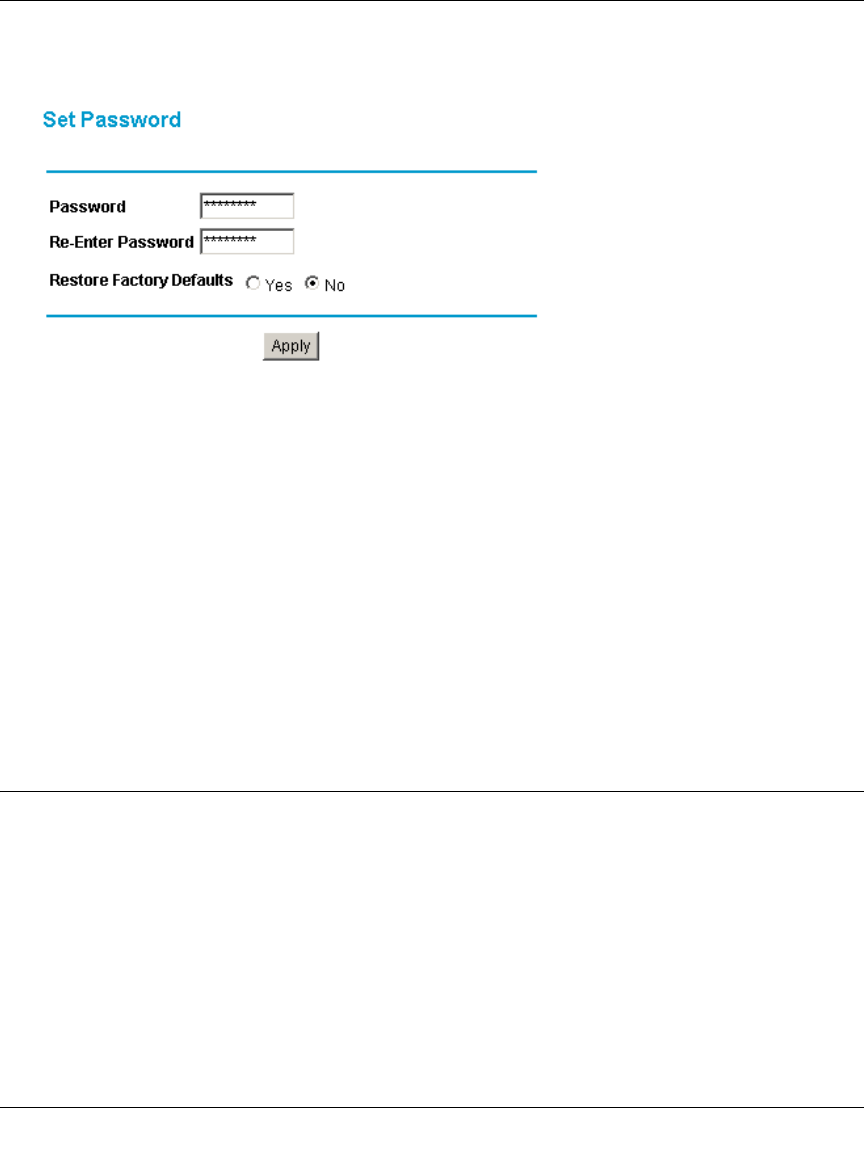
2. From the Main Menu of the browser interface, under the Maintenance heading, select Set
Password to bring up the menu shown in Figure 4-2.
Figure 4-2: Set Password menu
3. To change the password, first enter the old password, and then enter the new password twice.
4. If you would like to reset your gateway to its factory default settings select Yes for Restore
Factory Defaults. This will remove all configuration information you have entered.
5. Click Apply to save your changes.
Note: After changing the password, you will be required to log in again to continue the
configuration. If you have backed up the gateway settings previously, you should do a new
backup so that the saved settings file includes the new password.
Blocking Keywords, Sites, and Services
The gateway provides a variety of options for blocking Internet based content and
communications services. With its content filtering feature, the CG814W Gateway prevents
objectionable content from reaching your PCs. The CG814W allows you to control access to
Internet content by screening for keywords within Web addresses. It also has the capability to
block access to all sites except those that are explicitly allowed. Key content filtering options
include:
• Blocking access from your LAN to Internet locations that contain keywords that your specify.
• Blocking access to web sites that you specify as off-limits.
Reference Manual for the Model CG814W Wireless Cable Modem Gateway
Protecting Your Network 4-3
• Allowing access to only web sites that you specify as allowed.
The section below explains how to configure your gateway to perform these functions.
Procedure 4-2: Blocking Keywords and Domains
The CG814W Gateway allows you to restrict access to Internet content based on functions such as
web address keywords and web domains.
A domain name is the name of a particular web site. For example, for the address
www.NETGEAR.com, the domain name is NETGEAR.com.
1. Log in to the gateway at its default LAN address of http://192.168.0.1 with its default User
Name of admin, default password of password, or using whatever Password and LAN
address you have chosen for the gateway.
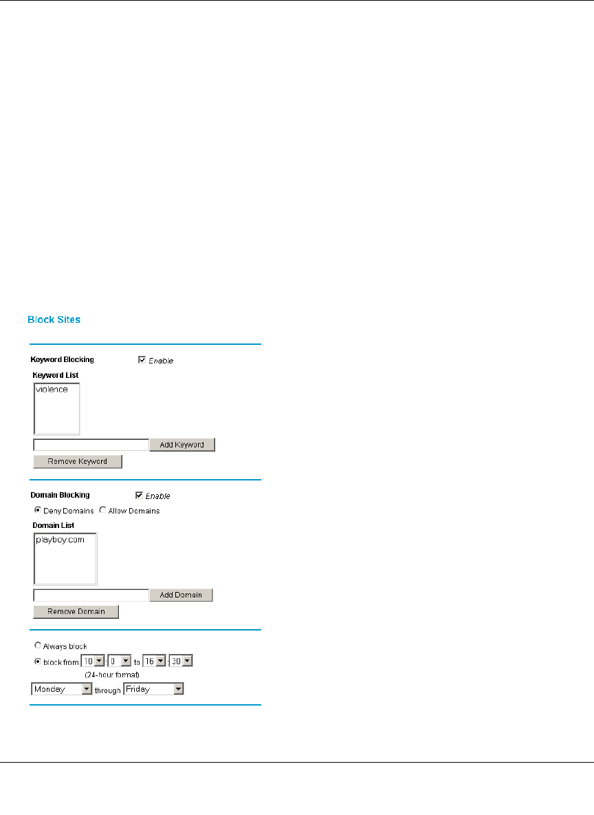
2. Click on the Block Sites link of the Content Filtering menu.
Figure 4-3: Block Sites menu

Reference Manual for the Model CG814W Wireless Cable Modem Gateway
4-4 Protecting Your Network
3. To enable keyword blocking or Domain Blocking, check the appropriate Enable box.
4. Enter Keywords into the Keyword List by typing then in the Add Keyword box, then, click
Add Keyword.
Some examples of Keyword applications follow:
• If the keyword “XXX” is specified, the URL <http://www.badstuff.com/xxx.html> is
blocked.
• If the keyword “.com” is specified, only websites with other domain suffixes (such as .edu
or .gov) can be viewed.
• Enter the keyword “.” to block all Internet browsing access.
Up to 8 entries are supported in the Keyword list.
5. Enter Domains into the Domain List by typing then in the Add Domain box, then, click Add
Domain.
If the domain “badstuff.com” is specified, the URL <http://www.badstuff.com/xxx.html> is
blocked, along with all other urls in the badstuff.com site.
Up to 8 entries are supported in the Keyword list.
6. To block access to the domains in the Domain List, select Deny Domains.
To allow access to only the domains in the Domain List, select Allow Domains. If the domain
“goodstuff.com” is specified, you will be able to access only sites on the goodstuff site.
7. To delete a keyword or domain, select it from the list, click Remove Keyword or Remove
Domain.
8. Configure the times when access rules apply in the Schedule section.
9. Click Apply to save your settings.
Using Port Blocking
Firewall rules are used to block or allow specific traffic passing through from one side to the other.
Inbound rules (WAN to LAN) restrict access by outsiders to private resources, selectively allowing
only specific outside users to access specific resources. Instructions for setting up inbound rules
can be found in “Port Forwarding“ on page -6. Outbound rules (LAN to WAN) determine what
outside resources local users can have access to. This section describes how to set up outbound
rules.
Reference Manual for the Model CG814W Wireless Cable Modem Gateway
Protecting Your Network 4-5
A firewall has two default rules, one for inbound traffic and one for outbound. The default rules of
the CG814W Gateway are:
• Inbound: Block all access from outside except responses to requests from the LAN side.
• Outbound: Allow all access from the LAN side to the outside.
You may define additional rules that will specify exceptions to the default rules. By adding custom
rules, you can block or allow access based on the service or application, source or destination IP
addresses, and time of day.
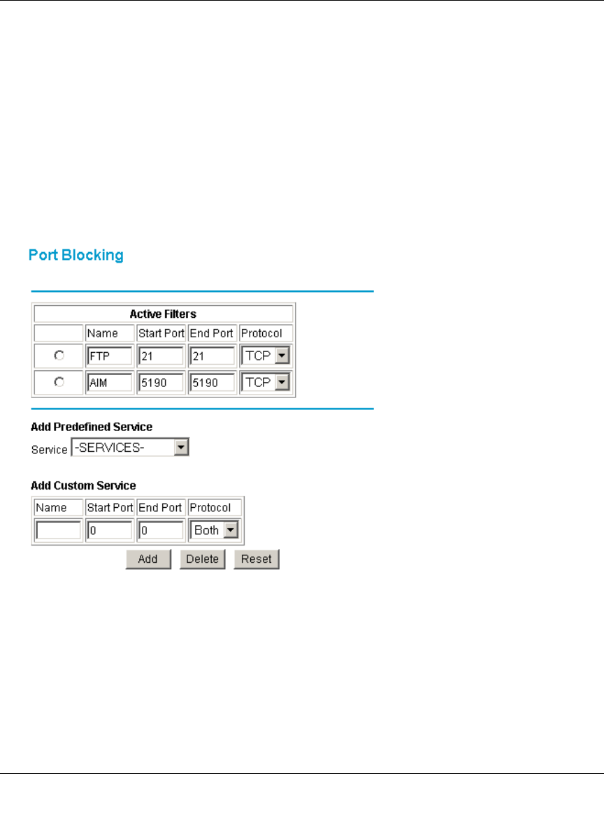
To configure outbound rules on the CG814W Gateway, click the Port Blocking link on the
Advanced section of the main menu.
Figure 4-4: Port Blocking menu
• To block outbound traffic, select the service you would like to block from the drop-down
list of predefined services. Click Add.
Reference Manual for the Model CG814W Wireless Cable Modem Gateway
4-6 Protecting Your Network
• If the service you would like to block is not in the predefined list, you can add a custom
service. Enter the range of ports you would like to block and select whether the ports are
TCP, UDP or Both. Click Add.
• To delete an existing rule, select its button on the left side of the table and click Delete.
Port Forwarding
Because the CG814W Gateway uses Network Address Translation (NAT), your network presents
only one IP address to the Internet, and outside users cannot directly address any of your local
computers. However, by defining an inbound rule you can make a local server (for example, a web
server or game server) visible and available to the Internet. The rule tells the gateway to direct
inbound traffic for a particular service to one local server based on the destination port number.
This is also known as Port Forwarding.
Considerations for Port Forwarding
• If the IP address of the local server PC is assigned by DHCP, it may change when the PC is
rebooted. To avoid this, you can assign a static IP address to your server outside the range that
is assigned by DHCP, but in the same subnet as the rest of your LAN. By default, the IP
addresses in the range of 192.168.0.2 through 192.168.0.9 are reserved for this.
• Local PCs must access the local server using the PCs’ local LAN address (192.168.0.XXX, by
default). Attempts by local PCs to access the server using the external WAN IP address will
fail.
Remember that allowing inbound services opens holes in your firewall. Only enable those ports
that are necessary for your network.
The following are two application examples of inbound rules.
Note: Some residential broadband ISP accounts do not allow you to run any server
processes (such as a Web or FTP server) from your location. Your ISP may periodically
check for servers and may suspend your account if it discovers any active services at
your location. If you are unsure, refer to the Acceptable Use Policy of your ISP.
Reference Manual for the Model CG814W Wireless Cable Modem Gateway
Protecting Your Network 4-7
.
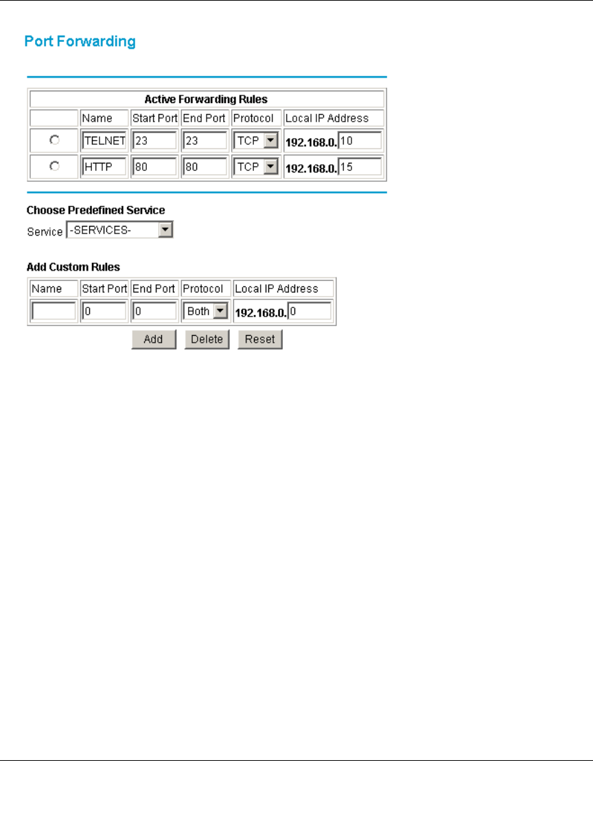
Figure 4-5: Port Forwarding menu
• To forward inbound traffic:
1. Select the service you would like to forward from the drop-down list of predefined
services.
If the service you would like to forward is not in the predefined list, you can add a
custom service. Enter the range of ports you would like to forward and select whether
the ports are TCP, UDP or Both.
2. Enter the IP address of the computer on your network to which you would like to
direct the inbound traffic
3. Click Add.
4. To access the local computer from the Internet, you must use the WAN address of your
gateway, which can be found on the Basic Settings page.
• To delete an existing rule, select its button on the left side of the table and click Delete.

Reference Manual for the Model CG814W Wireless Cable Modem Gateway
4-8 Protecting Your Network
Using Port Triggering
Port Triggering is an advanced feature that allows you to dynamically open inbound ports based on
outbound traffic on different ports. This is an advanced feature that can be used for gaming and
other internet applications.
Port Forwarding can typically be used to enable similar functionality, but it is static and has some
limitations. Ports will be open to traffic from the internet until the port forwarding rule is removed.
Additionally, port forwarding does not work well for some applications when your WAN IP
address is assigned by DHCP, and is changed frequently. Port Triggering opens in incoming port
temporarily and can does not require the server on the internet to track your IP address if it is
changed.
Port Triggering monitors outbound traffic. When the gateway detects traffic on the specified
outbound port, it remembers the IP address of the computer that sent the data and “triggers” the
incoming port. Incoming traffic on the triggered port is then forwarded to the triggering computer.
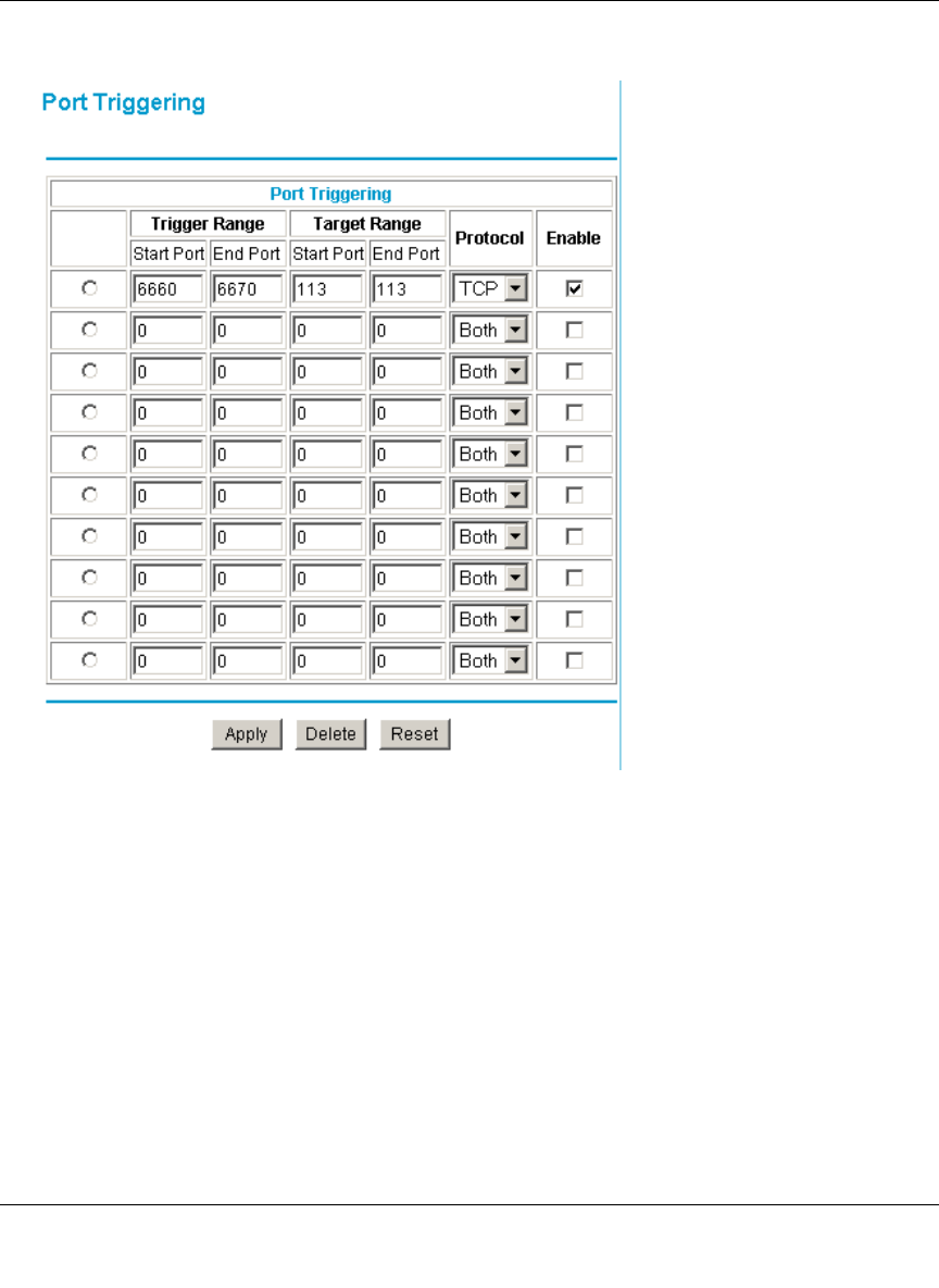
An example of Port Triggering for Internet Relay Chat (IRC) is shown in Figure 4-6. When you
connect to an IRC server, the server tries to connect back on port 113 to do an Ident lookup. Unless
you have configured Port Forwarding to open port 113, the traffic will be blocked. In this example,
the initial login to the server in the range of ports 6660 to 6670 will be detected. This will trigger
Reference Manual for the Model CG814W Wireless Cable Modem Gateway
Protecting Your Network 4-9
the gateway to temporarily forward port 113 to the PC that initiated the login.l
Figure 4-6: Port Triggering menu, with IRC example.
To configure Port Triggering:
1. In the Trigger Range, enter the outbound ports that will be monitored for activity. This will be
the “trigger”.
2. In the Target Range, enter the inbound ports that should be forwarded when the trigger occurs.
3. Select the appropriate protocol: TCP, UDP or Both.
4. Check the Enable box
5. Click Apply
To clear a Port Triggering rule, you can either remove the check from the Enable box, to
Reference Manual for the Model CG814W Wireless Cable Modem Gateway
4-10 Protecting Your Network
temporarily disable the rule, or you can select the rule and click Delete.
Setting Up A Default DMZ Host
The Default DMZ Server feature is helpful when using some online games and videoconferencing
applications that are incompatible with NAT. The gateway is programmed to recognize some of
these applications and to work properly with them, but there are other applications that may not
function well. In some cases, one local PC can run the application properly if that PC’s IP address
is entered as the Default DMZ Host.
Incoming traffic from the Internet is normally discarded by the gateway unless the traffic is a
response to one of your local computers or a service that you have configured in the Port
Forwarding or Port Triggering menu. Instead of discarding this traffic, you can have it forwarded
to one computer on your network. This computer is called the Default DMZ Host.
To assign a computer or server to be a DMZ Host, from the Main Menu, under Advanced, select
DMZ Host. Enter the IP address of the computer you would like to assign as a DMZ Host and click
Apply. To disable the DMZ Host, enter “0” and click Apply.
Respond to Ping on Internet WAN Port
If you want the gateway to respond to a 'ping' from the Internet, click the ‘Respond to Ping on
WAN Port’ check box. This should only be used as a diagnostic tool, since it allows your gateway
to be discovered. Don't check this box unless you have a specific reason to do so.
Note: For security, you should avoid using the Default DMZ Server feature. When a
computer is designated as the Default DMZ Server, it loses much of the protection of the
firewall, and is exposed to many exploits from the Internet. If compromised, the
computer can be used to attack your network.
Reference Manual for the Model CG814W Wireless Cable Modem Gateway
Managing Your Network 5-1
Chapter 5
Managing Your Network
This chapter describes how to perform network management tasks with your CG814W Wireless
Cable Modem Gateway.
Network Status Information
The CG814W provides a variety of status and usage information which is discussed below.
Viewing Gateway Status
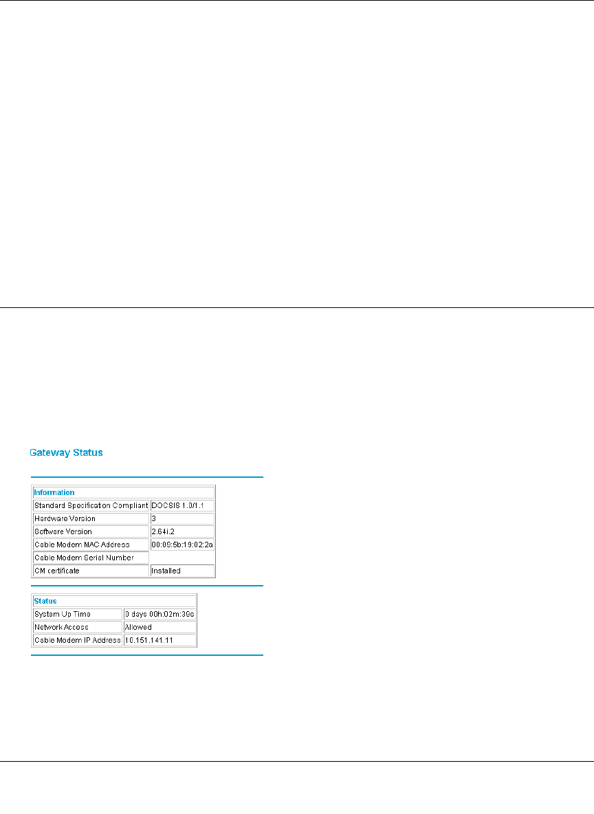
From the Main Menu, under Maintenance, select Gateway Status to view the screen in Figure 5-1.
Figure 5-1: Gateway Status screen

Reference Manual for the Model CG814W Wireless Cable Modem Gateway
5-2 Managing Your Network
This screen shows the following parameters:
Table 5-1. Menu 3.2 - Router Status Fields
Field Description
Information
Standard Specification
Compliant The specification to which the gateway’s cable interface is compatible.
Hardware Version The hardware version of the gateway.
Software Version The software version of the gateway.
Cable Modem MAC Address The MAC address being used by the Cable Modem port of the gateway.
This MAC address may need to be registered with your Cable Service
Provider.
Device MAC Address The MAC address of the router side of the gateway. This is the
equivalent of your PC when connected to a cable modem. You can use
the MAC Cloning feature to replace this MAC address with another
address when sending packets to the WAN.
Cable Modem Serial
Number The serial number of the gateway hardware.
CM Certificate If the Cable Modem certificate is Installed, it is possible for the service
provider to upgrade your Data Over Cable service securely.
Status
System Up Time This is the time since the gateway has registered with your cable service
provider.
Network Access This field will change to Allowed when the registration with your cable
service provider is complete.
Cable Modem IP Address The IP address of you gateway, as seen from the Internet.
Reference Manual for the Model CG814W Wireless Cable Modem Gateway
Managing Your Network 5-3
Connection Status
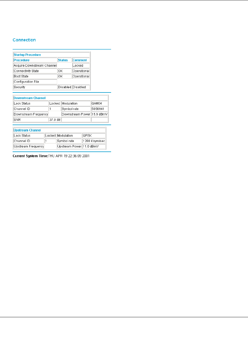
From the Main Menu, under Maintenance, select Connection to view the screen in Figure 5-2.
Figure 5-2: Connection screen
This screen shows detailed information about the status of the connection to your cable service
provider that can be used for troubleshooting. The gateway goes through the following steps to be
provisioned
1. Acquire and lock Downstream Channel
2. Acquire upstream parameters and range.
3. Lock Upstream Channel
4. Acquire IP Address through DHCP
Current System Time
The date and time is acquired from your cable service provider as part of the registration
procedure.
Reference Manual for the Model CG814W Wireless Cable Modem Gateway
5-4 Managing Your Network
Configuring LAN IP Settings
The LAN IP Setup menu allows configuration of LAN IP services such as the IP address of the
gateway and DHCP. These features can be found under the Advanced heading in the Main Menu
in the LAN IP menu.
LAN IP Setup
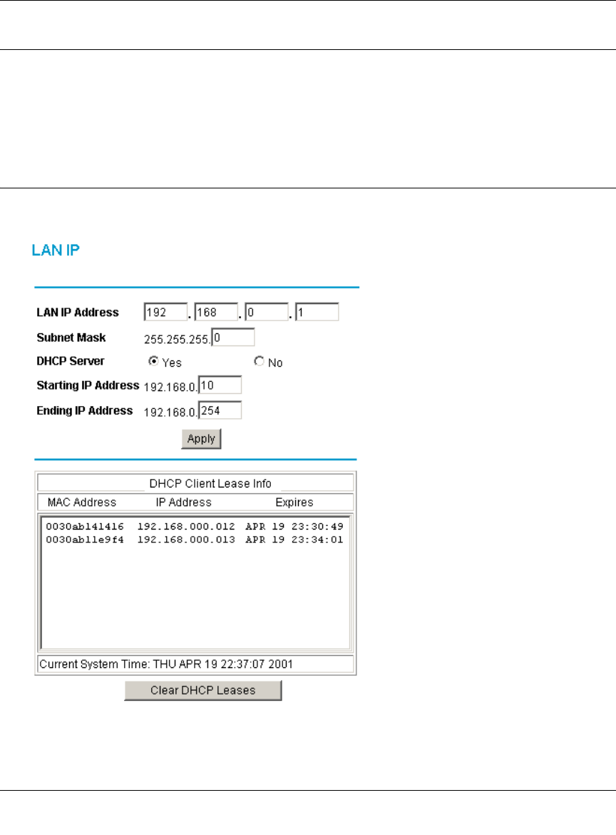
The LAN IP Setup menu is shown in Figure 5-3.0
Figure 5-3: LAN IP setup screen.
Reference Manual for the Model CG814W Wireless Cable Modem Gateway
Managing Your Network 5-5
The gateway is shipped preconfigured to use private IP addresses on the LAN side, and to act as a
DHCP server. The gateway’s default LAN IP configuration is:
• LAN IP addresses—192.168.0.1
• Subnet mask—255.255.255.
These addresses are part of the IETF-designated private address range for use in private networks,
and should be suitable in most applications. If your network has a requirement to use a different IP
addressing scheme, you can make those changes in this menu.
The LAN TCP/IP Setup parameters are:
• LAN IP Address
This is the IP address of the gateway.
• Subnet Mask
This is the LAN Subnet Mask of the gateway. Combined with the IP address, the Subnet Mask
allows a device to know which other addresses are local to it, and which must be reached
through a gateway or router
Using the Gateway as a DHCP Server
By default, the gateway will function as a DHCP (Dynamic Host Configuration Protocol) server,
allowing it to assign IP, DNS server, and default gateway addresses to all computers connected to
the router's LAN. The assigned default gateway address is the LAN address of the gateway. IP
addresses will be assigned to the attached PCs from a pool of addresses specified in this menu.
Each pool address is tested before it is assigned to avoid duplicate addresses on the LAN.
For most applications, the default DHCP and TCP/IP settings of the gateway are satisfactory. See
“IP Configuration by DHCP” on page B-10” for an explanation of DHCP and information about
how to assign IP addresses for your network.
If another device on your network will be the DHCP server, or if you will manually configure the
network settings of all of your computers, select NO for the DHCP Server, otherwise leave Yes
selected.
Note: If you change the LAN IP address of the gateway while connected through the
browser, you will be disconnected. You must then open a new connection to the new IP
address and log in again.
Reference Manual for the Model CG814W Wireless Cable Modem Gateway
5-6 Managing Your Network
Specify the pool of IP addresses to be assigned by setting the Starting IP Address and Ending IP
Address. These addresses should be part of the same IP address subnet as the gateway’s LAN IP
address. Using the default addressing scheme, you should define a range between 192.168.0.10
and 192.168.0.253. The range of IP addresses between 192.168.0.2 and 192.168.0.9 can be used
for devices with fixed addresses.
The gateway will deliver the following parameters to any LAN device that requests DHCP:
• An IP Address from the range you have defined
• Subnet Mask
• Gateway IP Address is the gateway’s LAN IP address
• Primary DNS Server, if you entered a Primary DNS address in the Basic Settings menu;
otherwise, the gateway’s LAN IP address
• Secondary DNS Server, if you entered a Secondary DNS address in the Basic Settings menu.
DHCP Client Lease Info
The DHCP Client Lease Info table lists information about each PC that has been assigned a DHCP
lease by the gateway. The MAC address of the PC, IP address assigned and the expiration time of
the DHCP lease are listed.
You can manually revoke the DHCP leases by clicking Clear DHCP Leases.
Note: The gateway implements a DNS Relay function. When it receives a DNS request
on the LAN, it passes it to the DNS server specified on the WAN. It then relays the
response back to the original requesting PC.
Reference Manual for the Model CG814W Wireless Cable Modem Gateway
Managing Your Network 5-7
Viewing and Emailing Logged Information
The gateway will log security-related events such as denied incoming service requests and hacker
probes. You can enable e-mail notification to receive these logs in an e-mail message. Log entries
are described in Table 5-4
Enabling Logs Event E-mail Notification
In order to receive logs and alerts by e-mail, you must provide your e-mail information in the
E-Mail section of the Logs menu:
• In the Contact Email Address, type the e-mail address to which the logs will be sent. Use a full
e-mail address (for example, ChrisXY@myISP.com).
• In the SMTP Server Name box, type the outgoing SMTP mail server of your ISP (for example,
mail.myISP.com). You may be able to find this information in the configuration menu of your
e-mail program. If you leave this box blank, no alerts or logs will be sent.
• Check the E-mail Alerts Enable box.
• Click E-mail Log to send the log immediately.
• Click Apply
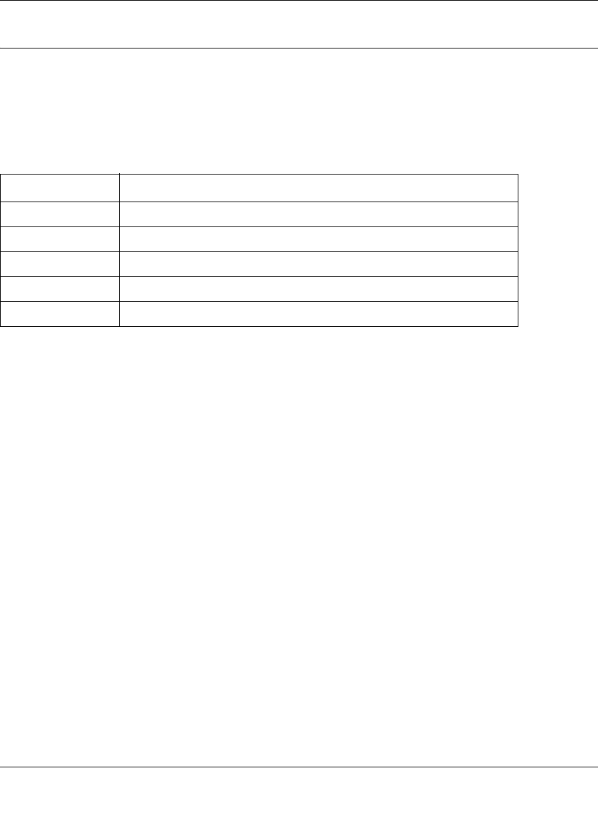
Table 5-4: Security Log entry descriptions
Field Description
Description The type of event and what action was taken if any.
Count This is a reference number for each event.
Last Occurrence The date and time the log entry was recorded.
Target The name or IP address of the destination device or website.
Source The IP address of the initiating device for this log entry.

Reference Manual for the Model CG814W Wireless Cable Modem Gateway
5-8 Managing Your Network
Erasing Configuration
The configuration settings of the CG814W Gateway are stored in a configuration file in the
gateway. This file can be reverted to factory default settings. The procedures below explain how to
do these tasks.
It is sometimes desirable to restore the gateway to the factory default settings. This can be done by
using the Erase function.
1. To erase the configuration, from the Main Menu, under Maintenance select Set Password.
Select Yes for Restore Factory Defaults and click Apply.
2. The gateway will then reboot automatically.
After an erase, the gateway's password will be password, the LAN IP address will be
192.168.0.1, and the router's DHCP client will be enabled.
Note: To restore the factory default configuration settings without knowing the login password or
IP address, you must use the Default Reset button on the rear panel of the gateway.
1. Using a paper clip, depress and hold the Default Reset Button. All the numbered Ethernet
LEDs will illuminate green.
2. Continue to depress the button for at least 5 seconds.
3. The gateway will reboot and clear its configuration information.
Running Diagnostic Utilities
The CG814W Gateway has a diagnostics feature. You can use the diagnostics menu to test
connectivity to PC using the Ping command:
Reference Manual for the Model CG814W Wireless Cable Modem Gateway
Managing Your Network 5-9
From the Main Menu of the browser interface, under the Maintenance heading, select the
Diagnostics menu, shown in Figure 5-5.
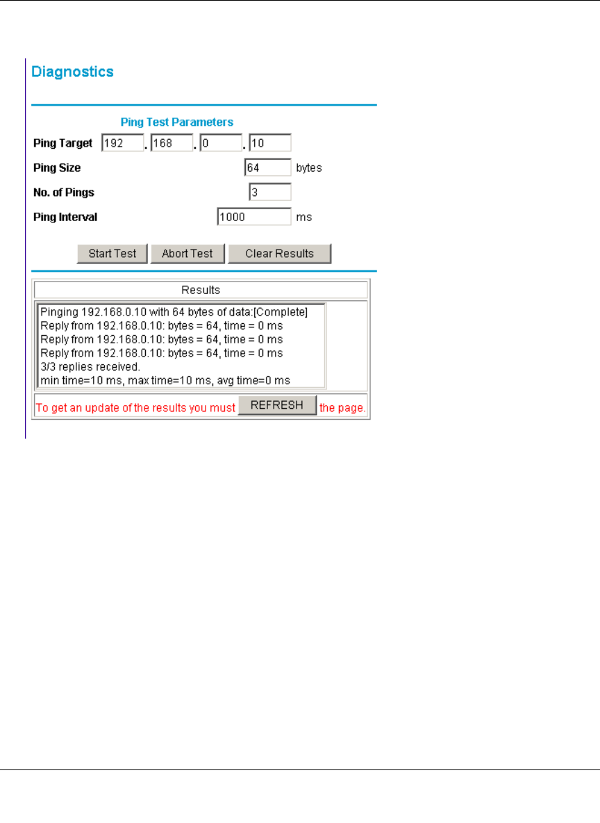
Figure 5-5: Diagnostics menu
To perform a Ping test
1. In the Ping Target section, enter the IP address of the PC you would like to ping.
2. If you would like to specify additional details, you can set the Ping Size, No. of Ping and Ping
Interval.
3. Click Start Test.
4. Click REFRESH to see the results of the Ping test.

Reference Manual for the Model CG814W Wireless Cable Modem Gateway
5-10 Managing Your Network

Reference Manual for the Model CG814W Wireless Cable Modem Gateway
Troubleshooting 6-1
Chapter 6
Troubleshooting
This chapter gives information about troubleshooting your CG814W Wireless Cable Modem
Gateway. For the common problems listed, go to the section indicated.
• Is the gateway on?
• Have I connected the gateway correctly?
Go to “Basic Functions” on page 6-1.
• I can’t access the gateway’s configuration with my browser.
Go to “Troubleshooting the Web Configuration Interface” on page 6-3.
• I’ve configured the gateway but I can’t access the Internet.
Go to “Troubleshooting the ISP Connection” on page 6-4.
• I can’t remember the gateway’s configuration password.
• I want to clear the configuration and start over again.
Go to “Erasing Configuration” on page 5-8.
Basic Functions
After you turn on power to the gateway, the following sequence of events should occur:
1. When power is first applied, verify that the Power LED is on.
2. Verify that the numbered ethernet LEDs come on momentarily.
3. After approximately 30 seconds, verify that:
f. The Local port Link LEDs are lit for any local ports that are connected.
g. The Test LED is not lit.

Reference Manual for the Model CG814W Wireless Cable Modem Gateway
6-2 Troubleshooting
h. The Internet Link port LED is lit.
If any of these conditions does not occur, refer to the appropriate following section.
Power LED Not On
If the Power and other LEDs are off when your gateway is turned on:
• Make sure that the power cord is properly connected to your gateway and that the power
supply adapter is properly connected to a functioning power outlet.
• Check that you are using the 12VDC power adapter supplied by NETGEAR for this product.
If the error persists, you have a hardware problem and should contact technical support.
Test LED Stays On
If the Test LED stays on continuously, there is a fault within the gateway.
If you experience problems with the Test LED:
• Cycle the power to see if the gateway recovers and the LED goes off
• If all LEDs including the Test LED are still on one minute after power up, clear the gateway’s
configuration to factory defaults. This will set the gateway’s IP address to 192.168.0.1. This
procedure is explained in “Erasing Configuration” on page 5-8.
If the error persists, you might have a hardware problem and should contact technical support.
Local Link LEDs Not On
If the Local Port Link LEDs do not light when the Ethernet connection is made, check the
following:
• Make sure that the Ethernet cable connections are secure at the gateway and at the hub or PC.
• Make sure that power is turned on to the connected hub or PC.
• Be sure you are using the correct cable:
— When connecting the gateway’s Internet port to a cable or DSL modem, use the cable that
was supplied with the cable or DSL modem. This cable could be a standard
straight-through Ethernet cable or an Ethernet crossover cable.

Reference Manual for the Model CG814W Wireless Cable Modem Gateway
Troubleshooting 6-3
Cable Link LED Not On
If the Cable Link LED does not light when connected to your cable television cable, check the
following:
• Make sure that the coaxial cable connections are secure at the gateway and at the wall jack.
• Make sure that your cable internet service has been provisioned by your cable service
provider. Your provider should verify that the signal quality is good enough for cable modem
service.
• Remove any excessive splitters you may have on your cable line. It may be necessary to run a
“home run” back to the point where the cable enters your home.
Troubleshooting the Web Configuration Interface
If you are unable to access the gateway’s Web Configuration interface from a PC on your local
network, check the following:
• Check the Ethernet connection between the PC and the gateway as described in the previous
section.
• Make sure your PC’s IP address is on the same subnet as the gateway. If you are using the
recommended addressing scheme, your PC’s address should be in the range of 192.168.0.10 to
192.168.0.254. Refer to “Verifying TCP/IP Properties” on page C-6 or “Configuring the
Macintosh for TCP/IP Networking” on page C-17 to find your PC’s IP address. Follow the
instructions in Appendix C to configure your PC.
Note: If your PC’s IP address is shown as 169.254.x.x:
Recent versions of Windows and MacOS will generate and assign an IP address if the
computer cannot reach a DHCP server. These auto-generated addresses are in the range of
169.254.x.x. If your IP address is in this range, check the connection from the PC to the
gateway and reboot your PC.
• If your gateway’s IP address has been changed and you don’t know the current IP address,
clear the gateway’s configuration to factory defaults. This will set the gateway’s IP address to
192.168.0.1. This procedure is explained in “Erasing Configuration” on page 5-8.
• Make sure your browser has Java, JavaScript, or ActiveX enabled. If you are using Internet
Explorer, click Refresh to be sure the Java applet is loaded.
• Try quitting the browser and launching it again.

Reference Manual for the Model CG814W Wireless Cable Modem Gateway
6-4 Troubleshooting
• Make sure you are using the correct login information. The factory default login name is
admin and the password is password. Make sure that CAPS LOCK is off when entering this
information.
If the gateway does not save changes you have made in the Web Configuration Interface, check the
following:
• When entering configuration settings, be sure to click the APPLY button before moving to
another menu or tab, or your changes are lost.
• Click the Refresh or Reload button in the Web browser. The changes may have occurred, but
the Web browser may be caching the old configuration.
Troubleshooting the ISP Connection
If your gateway is unable to access the Internet and your Cable Link LED is on, you may need to
register the Cable MAC Address and/or Device MAC Address of you gateway with your cable
service provider. This is described in “Connecting the CG814W Gateway” on page 2-4.
Additionally, your PC may not have the gateway configured as its TCP/IP gateway. If your PC
obtains its information from the gateway by DHCP, reboot the PC and verify the gateway address
as described in “DHCP Configuration of TCP/IP in Windows 2000 ” on page C-11.
Troubleshooting a TCP/IP Network Using a Ping Utility
Most TCP/IP terminal devices and routers contain a ping utility that sends an echo request packet
to the designated device. The device then responds with an echo reply. Troubleshooting a TCP/IP
network is made easier by using the ping utility in your PC or workstation.
Testing the LAN Path to Your Gateway
You can ping the gateway from your PC to verify that the LAN path to your gateway is set up
correctly.
To ping the gateway from a PC running Windows 95 or later:
1. From the Windows toolbar, click on the Start button and select Run.
2. In the field provided, type Ping followed by the IP address of the gateway, as in this example:

Reference Manual for the Model CG814W Wireless Cable Modem Gateway
Troubleshooting 6-5
ping 192.168.0.1
3. Click on OK.
You should see a message like this one:
Pinging <IP address> with 32 bytes of data
If the path is working, you see this message:
Reply from < IP address >: bytes=32 time=NN ms TTL=xxx
If the path is not working, you see this message:
Request timed out
If the path is not functioning correctly, you could have one of the following problems:
• Wrong physical connections
— Make sure the LAN port LED is on. If the LED is off, follow the instructions in
“Local Link LEDs Not On” on page 6-2.
— Check that the corresponding Link LEDs are on for your network interface card and
for the hub ports (if any) that are connected to your workstation and gateway.
• Wrong network configuration
— Verify that the Ethernet card driver software and TCP/IP software are both installed
and configured on your PC or workstation.
— Verify that the IP address for your gateway and your workstation are correct and that
the addresses are on the same subnet.
Testing the Path from Your PC to a Remote Device
After verifying that the LAN path works correctly, test the path from your PC to a remote device.
From the Windows run menu, type:
PING -n 10 <IP address>
where <IP address> is the IP address of a remote device such as your ISP’s DNS server.
If the path is functioning correctly, replies as in the previous section are displayed. If you do not
receive replies:

Reference Manual for the Model CG814W Wireless Cable Modem Gateway
6-6 Troubleshooting
— Check that your PC has the IP address of your gateway listed as the default gateway. If the
IP configuration of your PC is assigned by DHCP, this information will not be visible in
your PC’s Network Control Panel. Verify that the IP address of the gateway is listed as the
default gateway as described in “DHCP Configuration of TCP/IP in Windows 2000 ” on
page C-11.
— Check to see that the network address of your PC (the portion of the IP address specified
by the netmask) is different from the network address of the remote device.
— Check that your Cable Link LED is on.
— If your ISP assigned a host name to your PC, enter that host name as the Account Name in
the Basic Settings menu.
— Your ISP could be rejecting the Device MAC Address of your gateway because it does not
match the MAC Address of the PC you previously used to connect to a cable modem. In
this case you will need to clone your PCs MAC Address. Refer to “Connecting the
CG814W Gateway” on page 2-4.

Reference Manual for the Model CG814W Wireless Cable Modem Gateway
Technical Specifications A-1
Appendix A
Technical Specifications
This appendix provides technical specifications for the CG814W Wireless Cable Modem
Gateway.
Network Protocol and Standards Compatibility
Data and Routing Protocols: TCP/IP
DHCP server and client
DNS relay
NAT (many-to-one)
TFTP client
VPN pass through (IPSec, L2TP)
Power Adapter
North America (input): 120V, 60 Hz, input
All regions (output): 12 V DC @ 1.25A output, 20W maximum
Physical Specifications
Dimensions: 255 by 169 by 34 mm
10.0 by 6.7 by 1.3 in.
Weight: 0.54 kg
1.2 lb.
Environmental Specifications
Operating temperature: 32°-140° F (0° to 40° C)
Operating humidity: 90% maximum relative humidity, noncondensing
Electromagnetic Emissions
Meets requirements of: FCC Part 15 Class B
Interface Specifications

Reference Manual for the Model CG814W Wireless Cable Modem Gateway
A-2 Technical Specifications
Local: 10BASE-T or 100BASE-Tx, RJ-45
USB 1.1 Function
802.11b Wireless Access Point
Internet: DOCSIS 1.0, upgradable to DOCSIS 1.1

Reference Manual for the Model CG814W Wireless Cable Modem Gateway
Networks, Routing, and Firewall Basics B-1
Appendix B
Networks, Routing, and Firewall Basics
This chapter provides an overview of IP networks, routing, and firewalls.
Related Publications
As you read this document, you may be directed to various RFC documents for further
information. An RFC is a Request For Comment (RFC) published by the Internet Engineering
Task Force (IETF), an open organization that defines the architecture and operation of the Internet.
The RFC documents outline and define the standard protocols and procedures for the Internet. The
documents are listed on the World Wide Web at www.ietf.org and are mirrored and indexed at
many other sites worldwide.
Basic Router Concepts
Large amounts of bandwidth can be provided easily and relatively inexpensively in a local area
network (LAN). However, providing high bandwidth between a local network and the Internet can
be very expensive. Because of this expense, Internet access is usually provided by a slower-speed
wide-area network (WAN) link such as a cable or DSL modem. In order to make the best use of the
slower WAN link, a mechanism must be in place for selecting and transmitting only the data traffic
meant for the Internet. The function of selecting and forwarding this data is performed by a router.

Reference Manual for the Model CG814W Wireless Cable Modem Gateway
B-2 Networks, Routing, and Firewall Basics
What is a Router?
A router is a device that forwards traffic between networks based on network layer information in
the data and on routing tables maintained by the router. In these routing tables, a router builds up a
logical picture of the overall network by gathering and exchanging information with other routers
in the network. Using this information, the router chooses the best path for forwarding network
traffic.
Routers vary in performance and scale, number of routing protocols supported, and types of
physical WAN connection they support. The CG814W Wireless Cable Modem Gateway is a small
office router that routes the IP protocol over a single-user broadband connection.
Routing Information Protocol
One of the protocols used by a router to build and maintain a picture of the network is the Routing
Information Protocol (RIP). Using RIP, routers periodically update one another and check for
changes to add to the routing table.
The CG814W Gateway supports both the older RIP-1 and the newer RIP-2 protocols. Among
other improvements, RIP-2 supports subnet and multicast protocols. RIP is not required for most
home applications.
IP Addresses and the Internet
Because TCP/IP networks are interconnected across the world, every machine on the Internet must
have a unique address to make sure that transmitted data reaches the correct destination. Blocks of
addresses are assigned to organizations by the Internet Assigned Numbers Authority (IANA).
Individual users and small organizations may obtain their addresses either from the IANA or from
an Internet service provider (ISP). You can contact IANA at www.iana.org.
The Internet Protocol (IP) uses a 32-bit address structure. The address is usually written in dot
notation (also called dotted-decimal notation), in which each group of eight bits is written in
decimal form, separated by decimal points.
For example, the following binary address:
11000011 00100010 00001100 00000111
is normally written as:
195.34.12.7
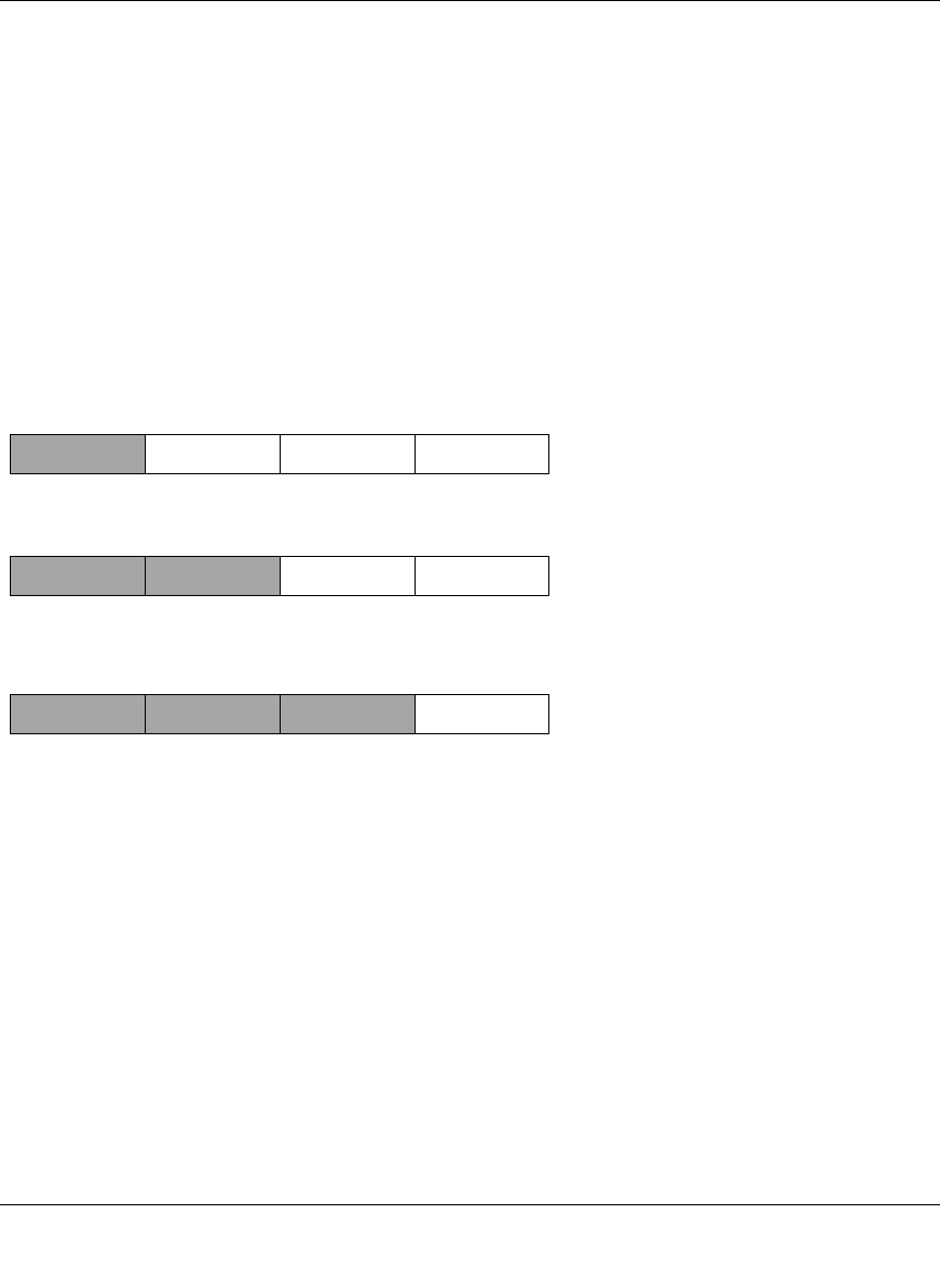
Reference Manual for the Model CG814W Wireless Cable Modem Gateway
Networks, Routing, and Firewall Basics B-3
The latter version is easier to remember and easier to enter into your computer.
In addition, the 32 bits of the address are subdivided into two parts. The first part of the address
identifies the network, and the second part identifies the host node or station on the network. The
dividing point may vary depending on the address range and the application.
There are five standard classes of IP addresses. These address classes have different ways of
determining the network and host sections of the address, allowing for different numbers of hosts
on a network. Each address type begins with a unique bit pattern, which is used by the TCP/IP
software to identify the address class. After the address class has been determined, the software
can correctly identify the host section of the address. The follow figure shows the three main
address classes, including network and host sections of the address for each address type.
Figure 6-1: Three Main Address Classes
The five address classes are:
• Class A
Class A addresses can have up to 16,777,214 hosts on a single network. They use an eight-bit
network number and a 24-bit node number. Class A addresses are in this range:
1.x.x.x to 126.x.x.x.
• Class B
Class B addresses can have up to 65,354 hosts on a network. A Class B address uses a 16-bit
network number and a 16-bit node number. Class B addresses are in this range:
128.1.x.x to 191.254.x.x.
7261
C
lass A
N
etwork Node
C
lass B
C
lass C
Network Node
Network Node

Reference Manual for the Model CG814W Wireless Cable Modem Gateway
B-4 Networks, Routing, and Firewall Basics
• Class C
Class C addresses can have 254 hosts on a network. Class C addresses use 24 bits for the
network address and eight bits for the node. They are in this range:
192.0.1.x to 223.255.254.x.
• Class D
Class D addresses are used for multicasts (messages sent to many hosts). Class D addresses are
in this range:
224.0.0.0 to 239.255.255.255.
• Class E
Class E addresses are for experimental use.
This addressing structure allows IP addresses to uniquely identify each physical network and each
node on each physical network.
For each unique value of the network portion of the address, the base address of the range (host
address of all zeros) is known as the network address and is not usually assigned to a host. Also,
the top address of the range (host address of all ones) is not assigned, but is used as the broadcast
address for simultaneously sending a packet to all hosts with the same network address.
Netmask
In each of the address classes previously described, the size of the two parts (network address and
host address) is implied by the class. This partitioning scheme can also be expressed by a netmask
associated with the IP address. A netmask is a 32-bit quantity that, when logically combined (using
an AND operator) with an IP address, yields the network address. For instance, the netmasks for
Class A, B, and C addresses are 255.0.0.0, 255.255.0.0, and 255.255.255.0, respectively.
For example, the address 192.168.170.237 is a Class C IP address whose network portion is the
upper 24 bits. When combined (using an AND operator) with the Class C netmask, as shown here,
only the network portion of the address remains:
11000000 10101000 10101010 11101101 (192.168.170.237)
combined with:
11111111 11111111 11111111 00000000 (255.255.255.0)
Equals:
11000000 10101000 10101010 00000000 (192.168.170.0)
Reference Manual for the Model CG814W Wireless Cable Modem Gateway
Networks, Routing, and Firewall Basics B-5
As a shorter alternative to dotted-decimal notation, the netmask may also be expressed in terms of
the number of ones from the left. This number is appended to the IP address, following a backward
slash (/), as “/n.” In the example, the address could be written as 192.168.170.237/24, indicating
that the netmask is 24 ones followed by 8 zeros.
Subnet Addressing
By looking at the addressing structures, you can see that even with a Class C address, there are a
large number of hosts per network. Such a structure is an inefficient use of addresses if each end of
a routed link requires a different network number. It is unlikely that the smaller office LANs would
have that many devices. You can resolve this problem by using a technique known as subnet
addressing.
Subnet addressing allows us to split one IP network address into smaller multiple physical
networks known as subnetworks. Some of the node numbers are used as a subnet number instead.
A Class B address gives us 16 bits of node numbers translating to 64,000 nodes. Most
organizations do not use 64,000 nodes, so there are free bits that can be reassigned. Subnet
addressing makes use of those bits that are free, as shown below.
Figure 6-2: Example of Subnetting a Class B Address
A Class B address can be effectively translated into multiple Class C addresses. For example, the
IP address of 172.16.0.0 is assigned, but node addresses are limited to 255 maximum, allowing
eight extra bits to use as a subnet address. The IP address of 172.16.97.235 would be interpreted as
IP network address 172.16, subnet number 97, and node number 235. In addition to extending
the number of addresses available, subnet addressing provides other benefits. Subnet addressing
allows a network manager to construct an address scheme for the network by using different
subnets for other geographical locations in the network or for other departments in the
organization.
7262
C
lass B
Network Subnet Node
Reference Manual for the Model CG814W Wireless Cable Modem Gateway
B-6 Networks, Routing, and Firewall Basics
Although the preceding example uses the entire third octet for a subnet address, note that you are
not restricted to octet boundaries in subnetting. To create more network numbers, you need only
shift some bits from the host address to the network address. For instance, to partition a Class C
network number (192.68.135.0) into two, you shift one bit from the host address to the network
address. The new netmask (or subnet mask) is 255.255.255.128. The first subnet has network
number 192.68.135.0 with hosts 192.68.135.1 to 129.68.135.126, and the second subnet has
network number 192.68.135.128 with hosts 192.68.135.129 to 192.68.135.254.
The following table lists the additional subnet mask bits in dotted-decimal notation. To use the
table, write down the original class netmask and replace the 0 value octets with the dotted-decimal
value of the additional subnet bits. For example, to partition your Class C network with subnet
mask 255.255.255.0 into 16 subnets (4 bits), the new subnet mask becomes 255.255.255.240.
The following table displays several common netmask values in both the dotted-decimal and the
mask length formats.
Note: The number 192.68.135.127 is not assigned because it is the broadcast address
of the first subnet. The number 192.68.135.128 is not assigned because it is the network
address of the second subnet.
Table 6-1. Netmask Notation Translation Table for One Octet
Number of Bits Dotted-Decimal Value
1128
2192
3224
4240
5248
6252
7254
8255
Table 6-2. Netmask Formats
Dotted-Decimal Masklength
255.0.0.0 /8
255.255.0.0 /16

Reference Manual for the Model CG814W Wireless Cable Modem Gateway
Networks, Routing, and Firewall Basics B-7
NETGEAR strongly recommends that you configure all hosts on a LAN segment to use the same
netmask for the following reasons:
• So that hosts recognize local IP broadcast packets
When a device broadcasts to its segment neighbors, it uses a destination address of the local
network address with all ones for the host address. In order for this scheme to work, all devices
on the segment must agree on which bits comprise the host address.
• So that a local router or bridge recognizes which addresses are local and which are remote
Private IP Addresses
If your local network is isolated from the Internet (for example, when using NAT), you can assign
any IP addresses to the hosts without problems. However, the IANA has reserved the following
three blocks of IP addresses specifically for private networks:
10.0.0.0 - 10.255.255.255
172.16.0.0 - 172.31.255.255
192.168.0.0 - 192.168.255.255
NETGEAR recommends that you choose your private network number from this range. The
DHCP server of the CG814W Gateway is preconfigured to automatically assign private addresses.
Regardless of your particular situation, do not create an arbitrary IP address; always follow the
guidelines explained here. For more information about address assignment, refer to RFC 1597,
Address Allocation for Private Internets, and RFC 1466, Guidelines for Management of IP
Address Space. The Internet Engineering Task Force (IETF) publishes RFCs on its Web site at
www.ietf.org.
255.255.255.0 /24
255.255.255.128 /25
255.255.255.192 /26
255.255.255.224 /27
255.255.255.240 /28
255.255.255.248 /29
255.255.255.252 /30
255.255.255.254 /31
255.255.255.255 /32
Table 6-2. Netmask Formats
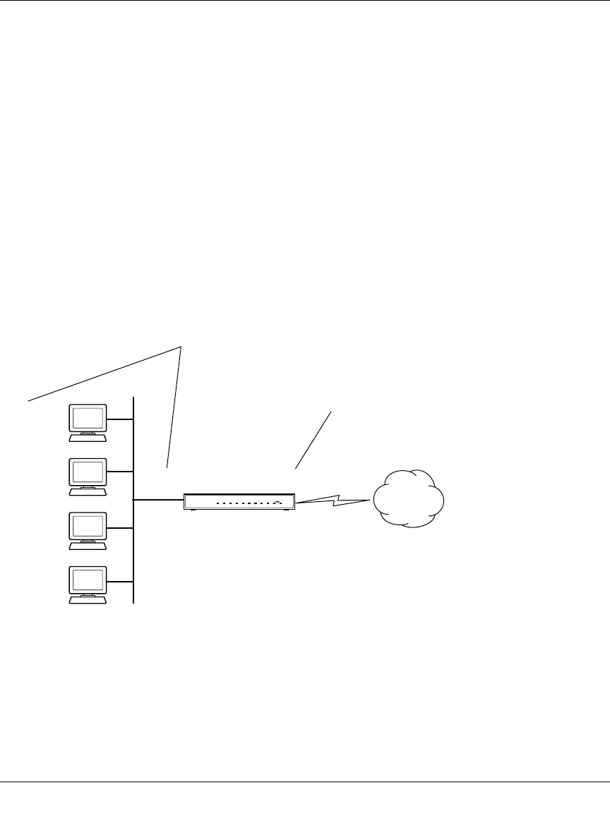
Reference Manual for the Model CG814W Wireless Cable Modem Gateway
B-8 Networks, Routing, and Firewall Basics
Single IP Address Operation Using NAT
In the past, if multiple PCs on a LAN needed to access the Internet simultaneously, you had to
obtain a range of IP addresses from the ISP. This type of Internet account is more costly than a
single-address account typically used by a single user with a modem, rather than a router. The
CG814W Gateway employs an address-sharing method called Network Address Translation
(NAT). This method allows several networked PCs to share an Internet account using only a single
IP address, which may be statically or dynamically assigned by your ISP.
The router accomplishes this address sharing by translating the internal LAN IP addresses to a
single address that is globally unique on the Internet. The internal LAN IP addresses can be either
private addresses or registered addresses. For more information about IP address translation, refer
to RFC 1631, The IP Network Address Translator (NAT).
The following figure illustrates a single IP address operation.
Figure 6-3: Single IP Address Operation Using NAT
7786EA
1
92.168.0.2
1
92.168.0.3
1
92.168.0.4
1
92.168.0.5
192.168.0.1 172.21.15.105
Private IP addresses
assigned by user
Internet
IP addresses
assigned by ISP

Reference Manual for the Model CG814W Wireless Cable Modem Gateway
Networks, Routing, and Firewall Basics B-9
This scheme offers the additional benefit of firewall-like protection because the internal LAN
addresses are not available to the Internet through the translated connection. All incoming
inquiries are filtered out by the router. This filtering can prevent intruders from probing your
system. However, using port forwarding, you can allow one PC (for example, a Web server) on
your local network to be accessible to outside users.
MAC Addresses and Address Resolution Protocol
An IP address alone cannot be used to deliver data from one LAN device to another. To send data
between LAN devices, you must convert the IP address of the destination device to its media
access control (MAC) address. Each device on an Ethernet network has a unique MAC address,
which is a 48-bit number assigned to each device by the manufacturer. The technique that
associates the IP address with a MAC address is known as address resolution. Internet Protocol
uses the Address Resolution Protocol (ARP) to resolve MAC addresses.
If a device sends data to another station on the network and the destination MAC address is not yet
recorded, ARP is used. An ARP request is broadcast onto the network. All stations on the network
receive and read the request. The destination IP address for the chosen station is included as part of
the message so that only the station with this IP address responds to the ARP request. All other
stations discard the request.
Related Documents
The station with the correct IP address responds with its own MAC address directly to the sending
device. The receiving station provides the transmitting station with the required destination MAC
address. The IP address data and MAC address data for each station are held in an ARP table. The
next time data is sent, the address can be obtained from the address information in the table.
For more information about address assignment, refer to the IETF documents RFC 1597, Address
Allocation for Private Internets, and RFC 1466, Guidelines for Management of IP Address Space.
For more information about IP address translation, refer to RFC 1631, The IP Network Address
Translator (NAT).

Reference Manual for the Model CG814W Wireless Cable Modem Gateway
B-10 Networks, Routing, and Firewall Basics
Domain Name Server
Many of the resources on the Internet can be addressed by simple descriptive names such as
www.NETGEAR.com. This addressing is very helpful at the application level, but the descriptive
name must be translated to an IP address in order for a user to actually contact the resource. Just as
a telephone directory maps names to phone numbers, or as an ARP table maps IP addresses to
MAC addresses, a domain name system (DNS) server maps descriptive names of network
resources to IP addresses.
When a PC accesses a resource by its descriptive name, it first contacts a DNS server to obtain the
IP address of the resource. The PC sends the desired message using the IP address. Many large
organizations, such as ISPs, maintain their own DNS servers and allow their customers to use the
servers to look up addresses.
IP Configuration by DHCP
When an IP-based local area network is installed, each PC must be configured with an IP address.
If the PCs need to access the Internet, they should also be configured with a gateway address and
one or more DNS server addresses. As an alternative to manual configuration, there is a method by
which each PC on the network can automatically obtain this configuration information. A device
on the network may act as a Dynamic Host Configuration Protocol (DHCP) server. The DHCP
server stores a list or pool of IP addresses, along with other information (such as gateway and DNS
addresses) that it may assign to the other devices on the network. The CG814W Gateway has the
capacity to act as a DHCP server.
The CG814W Gateway also functions as a DHCP client when connecting to the ISP. The gateway
can automatically obtain an IP address, subnet mask, DNS server addresses, and a gateway address
if the ISP provides this information by DHCP.
Internet Security and Firewalls
When your LAN connects to the Internet through a router, an opportunity is created for outsiders
to access or disrupt your network. A NAT router provides some protection because by the very
nature of the Network Address Translation (NAT) process, the network behind the NAT router is
shielded from access by outsiders on the Internet. However, there are methods by which a
determined hacker can possibly obtain information about your network or at the least can disrupt
your Internet access. A greater degree of protection is provided by a firewall router.

Reference Manual for the Model CG814W Wireless Cable Modem Gateway
Networks, Routing, and Firewall Basics B-11
What is a Firewall?
A firewall is a device that protects one network from another, while allowing communication
between the two. A firewall incorporates the functions of the NAT router, while adding features for
dealing with a hacker intrusion or attack. Several known types of intrusion or attack can be
recognized when they occur. When an incident is detected, the firewall can log details of the
attempt, and can optionally send email to an administrator notifying them of the incident. Using
information from the log, the administrator can take action with the ISP of the hacker. In some
types of intrusions, the firewall can fend off the hacker by discarding all further packets from the
hacker’s IP address for a period of time.
Stateful Packet Inspection
Unlike simple Internet sharing routers, a firewall uses a process called stateful packet inspection to
ensure secure firewall filtering to protect your network from attacks and intrusions. Since
user-level applications such as FTP and Web browsers can create complex patterns of network
traffic, it is necessary for the firewall to analyze groups of network connection “states.” Using
Stateful Packet Inspection, an incoming packet is intercepted at the network layer and then
analyzed for state-related information associated with all network connections. A central cache
within the firewall keeps track of the state information associated with all network connections.
All traffic passing through the firewall is analyzed against the state of these connections in order to
determine whether or not it will be allowed to pass through or rejected.
Denial of Service Attack
A hacker may be able to prevent your network from operating or communicating by launching a
Denial of Service (DoS) attack. The method used for such an attack can be as simple as merely
flooding your site with more requests than it can handle. A more sophisticated attack may attempt
to exploit some weakness in the operating system used by your router or gateway. Some operating
systems can be disrupted by simply sending a packet with incorrect length information.

Reference Manual for the Model CG814W Wireless Cable Modem Gateway
B-12 Networks, Routing, and Firewall Basics
Wireless Networking Overview
The CG814W Gateway conforms to the Institute of Electrical and Electronics Engineers (IEEE)
802.11b standard for wireless LANs (WLANs). On an 802.11b wireless link, data is encoded using
direct-sequence spread-spectrum (DSSS) technology and is transmitted in the unlicensed radio
spectrum at 2.5GHz. The maximum data rate for the wireless link is 11 Mbps, but it will
automatically back down from 11 Mbps to 5.5, 2, and 1 Mbps when the radio signal is weak or
when interference is detected.
The 802.11b standard is also called Wireless Ethernet or Wi-Fi by the Wireless Ethernet
Compatibility Alliance (WECA, see http://www.wi-fi.net), an industry standard group promoting
interoperability among 802.11b devices. The 802.11b standard offers two methods for configuring
a wireless network - ad hoc and infrastructure.
Infrastructure Mode
With a wireless Access Point, you can operate the wireless LAN in the infrastructure mode. This
mode provides wireless connectivity to multiple wireless network devices within a fixed range or
area of coverage, interacting with wireless nodes via an antenna.
In the infrastructure mode, the wireless access point converts airwave data into wired Ethernet
data, acting as a bridge between the wired LAN and wireless clients. Connecting multiple Access
Points via a wired Ethernet backbone can further extend the wireless network coverage. As a
mobile computing device moves out of the range of one access point, it moves into the range of
another. As a result, wireless clients can freely roam from one Access Point domain to another and
still maintain seamless network connection.
Ad Hoc Mode (Peer-to-Peer Workgroup)
In an ad hoc network, computers are brought together as needed; thus, there is no structure or fixed
points to the network - each node can generally communicate with any other node. There is no
Access Point involved in this configuration. This mode enables you to quickly set up a small
wireless workgroup and allows workgroup members to exchange data or share printers as
supported by Microsoft networking in the various Windows operating systems. Some vendors also
refer to ad hoc networking as peer-to-peer group networking.
In this configuration, network packets are directly sent and received by the intended transmitting
and receiving stations. As long as the stations are within range of one another, this is the easiest
and least expensive way to set up a wireless network.

Reference Manual for the Model CG814W Wireless Cable Modem Gateway
Networks, Routing, and Firewall Basics B-13
Network Name: Extended Service Set Identification (ESSID)
The Extended Service Set Identification (ESSID) is one of two types of Service Set Identification
(SSID). In an ad hoc wireless network with no access points, the Basic Service Set Identification
(BSSID) is used. In an infrastructure wireless network that includes an access point, the ESSID is
used, but may still be referred to as SSID.
An SSID is a thirty-two character (maximum) alphanumeric key identifying the name of the
wireless local area network. Some vendors refer to the SSID as network name. For the wireless
devices in a network to communicate with each other, all devices must be configured with the
same SSID.
Authentication and WEP
The absence of a physical connection between nodes makes the wireless links vulnerable to
eavesdropping and information theft. To provide a certain level of security, the IEEE 802.11
standard has defined two types of authentication methods, Open System and Shared Key. With
Open System authentication, a wireless PC can join any network and receive any messages that are
not encrypted. With Shared Key authentication, only those PCs that possess the correct
authentication key can join the network. By default, IEEE 802.11 wireless devices operate in an
Open System network.
Wired Equivalent Privacy (WEP) data encryption is used when the wireless devices are configured
to operate in Shared Key authentication mode. There are two shared key methods implemented in
most commercially available products, 64-bit and 128-bit WEP data encryption.
802.11b Authentication
The 802.11b standard defines several services that govern how two 802.11b devices communicate.
The following events must occur before an 802.11b Station can communicate with an Ethernet
network through an access point such as the one built in to the CG814W Gateway:
1. Turn on the wireless station.
2. The station listens for messages from any access points that are in range.
3. The station finds a message from an access point that has a matching SSID.
4. The station sends an authentication request to the access point.
5. The access point authenticates the station.
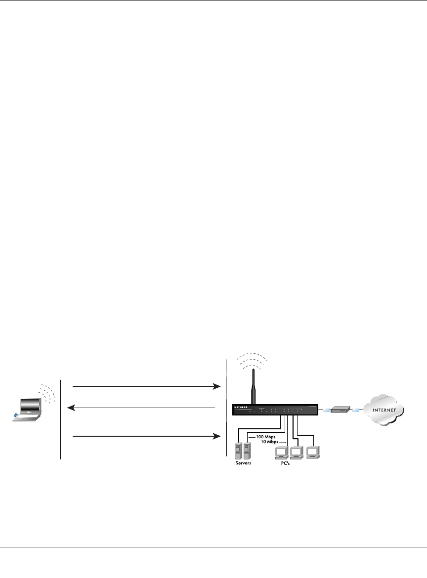
Reference Manual for the Model CG814W Wireless Cable Modem Gateway
B-14 Networks, Routing, and Firewall Basics
6. The station sends an association request to the access point.
7. The access point associates with the station.
8. The station can now communicate with the Ethernet network through the access point.
An access point must authenticate a station before the station can associate with the access point or
communicate with the network. The IEEE 802.11b standard defines two types of authentication:
Open System and Shared Key.
• Open System Authentication allows any device to join the network, assuming that the device
SSID matches the access point SSID. Alternatively, the device can use the “ANY” SSID
option to associate with any available Access Point within range, regardless of its SSID.
• Shared Key Authentication requires that the station and the access point have the same WEP
Key to authenticate. These two authentication procedures are described below.
Open System Authentication
The following steps occur when two devices use Open System Authentication:
1. The station sends an authentication request to the access point.
2. The access point authenticates the station.
3. The station associates with the access point and joins the network.
This process is illustrated in below.
Figure 6-4: 802.11b open system authentication
INTERNET LOCAL
ACT 1234567 8
LNK
LNK/ACT
100
Cable/DSL ProSafeWirelessVPN SecurityFirewall
MODEL FVM318
PWR TEST
WLAN
Enable
Access Point
1) Authentication request sent to AP
2) AP authenticates
3) Client connects to network
802.11b Authentication
Open System Steps
Cable or
DLS modem
Client
attempting
to connect
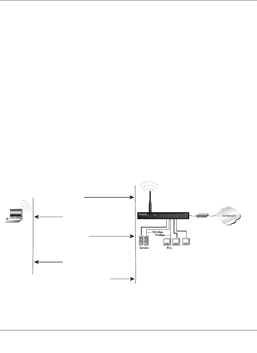
Reference Manual for the Model CG814W Wireless Cable Modem Gateway
Networks, Routing, and Firewall Basics B-15
Shared Key Authentication
The following steps occur when two devices use Shared Key Authentication:
1. The station sends an authentication request to the access point.
2. The access point sends challenge text to the station.
3. The station uses its configured 64-bit or 128-bit default key to encrypt the challenge text, and
sends the encrypted text to the access point.
4. The access point decrypts the encrypted text using its configured WEP Key that corresponds
to the station’s default key. The access point compares the decrypted text with the original
challenge text. If the decrypted text matches the original challenge text, then the access point
and the station share the same WEP Key and the access point authenticates the station.
5. The station connects to the network.
If the decrypted text does not match the original challenge text (i.e., the access point and station do
not share the same WEP Key), then the access point will refuse to authenticate the station and the
station will be unable to communicate with either the 802.11b network or Ethernet network.
This process is illustrated in below.
Figure 6-5: 802.11b shared key authentication
INTERNET LOCAL
ACT
12345678
LNK
LNK/ACT
100
Cable/DSL ProSafeWirelessVPN SecurityFirewall
MODEL FVM318
PWR TEST
WLAN
Enable
Access Point1) Authentication
request sent to AP
2) AP sends challenge text
3) Client encrypts
challenge text and
sends it back to AP
4) AP decrypts, and if correct,
authenticates client
5) Client connects to network
802.11b Authentication
Shared Key Steps
Cable or
DLS modem
Client
attempting
to connect

Reference Manual for the Model CG814W Wireless Cable Modem Gateway
B-16 Networks, Routing, and Firewall Basics
Overview of WEP Parameters
Before enabling WEP on an 802.11b network, you must first consider what type of encryption you
require and the key size you want to use. Typically, there are three WEP Encryption options
available for 802.11b products:
1. Do Not Use WEP: The 802.11b network does not encrypt data. For authentication purposes, the
network uses Open System Authentication.
2. Use WEP for Encryption: A transmitting 802.11b device encrypts the data portion of every
packet it sends using a configured WEP Key. The receiving 802.11b device decrypts the data using
the same WEP Key. For authentication purposes, the 802.11b network uses Open System
Authentication.
3. Use WEP for Authentication and Encryption: A transmitting 802.11b device encrypts the
data portion of every packet it sends using a configured WEP Key. The receiving 802.11b device
decrypts the data using the same WEP Key. For authentication purposes, the 802.11b network uses
Shared Key Authentication.
Note: Some 802.11b access points also support Use WEP for Authentication Only (Shared Key
Authentication without data encryption).
Key Size
The IEEE 802.11b standard supports two types of WEP encryption: 40-bit and 128-bit.
The 64-bit WEP data encryption method, allows for a five-character (40-bit) input. Additionally,
24 factory-set bits are added to the forty-bit input to generate a 64-bit encryption key. (The 24
factory-set bits are not user-configurable). This encryption key will be used to encrypt/decrypt all
data transmitted via the wireless interface. Some vendors refer to the 64-bit WEP data encryption
as 40-bit WEP data encryption since the user-configurable portion of the encryption key is 40 bits
wide.
The 128-bit WEP data encryption method consists of 104 user-configurable bits. Similar to the
forty-bit WEP data encryption method, the remaining 24 bits are factory set and not user
configurable. Some vendors allow passphrases to be entered instead of the cryptic hexadecimal
characters to ease encryption key entry.
128-bit encryption is stronger than 40-bit encryption, but 128-bit encryption may not be available
outside of the United States due to U.S. export regulations.

Reference Manual for the Model CG814W Wireless Cable Modem Gateway
Networks, Routing, and Firewall Basics B-17
When configured for 40-bit encryption, 802.11b products typically support up to four WEP Keys.
Each 40-bit WEP Key is expressed as 5 sets of two hexadecimal digits (0-9 and A-F). For
example, “12 34 56 78 90” is a 40-bit WEP Key.
When configured for 128-bit encryption, 802.11b products typically support four WEP Keys but
some manufacturers support only one 128-bit key. The 128-bit WEP Key is expressed as 13 sets of
two hexadecimal digits (0-9 and A-F). For example, “12 34 56 78 90 AB CD EF 12 34 56 78 90”
is a 128-bit WEP Key.
Note: Typically, 802.11b access points can store up to four 128-bit WEP Keys but some 802.11b
client adapters can only store one. Therefore, make sure that your 802.11b access and client
adapters configurations match.
WEP Configuration Options
The WEP settings must match on all 802.11b devices that are within the same wireless network as
identified by the SSID. In general, if your mobile clients will roam between access points, then all
of the 802.11b access points and all of the 802.11b client adapters on the network must have the
same WEP settings.
Note: Whatever keys you enter for an AP, you must also enter the same keys for the client adapter
in the same order. In other words, WEP key 1 on the AP must match WEP key 1 on the client
adapter, WEP key 2 on the AP must match WEP key 2 on the client adapter, etc.
Note: The AP and the client adapters can have different default WEP Keys as long as the keys are
in the same order. In other words, the AP can use WEP key 2 as its default key to transmit while a
client adapter can use WEP key 3 as its default key to transmit. The two devices will communicate
as long as the AP’s WEP key 2 is the same as the client’s WEP key 2 and the AP’s WEP key 3 is
the same as the client’s WEP key 3.

Reference Manual for the Model CG814W Wireless Cable Modem Gateway
B-18 Networks, Routing, and Firewall Basics
Wireless Channels
IEEE 802.11 wireless nodes communicate with each other using radio frequency signals in the
ISM (Industrial, Scientific, and Medical) band between 2.4 GHz and 2.5 GHz. Neighboring
channels are 5 MHz apart. However, due to spread spectrum effect of the signals, a node sending
signals using a particular channel will utilize frequency spectrum 12.5 MHz above and below the
center channel frequency. As a result, two separate wireless networks using neighboring channels
(for example, channel 1 and channel 2) in the same general vicinity will interfere with each other.
Applying two channels that allow the maximum channel separation will decrease the amount of
channel cross-talk, and provide a noticeable performance increase over networks with minimal
channel separation.
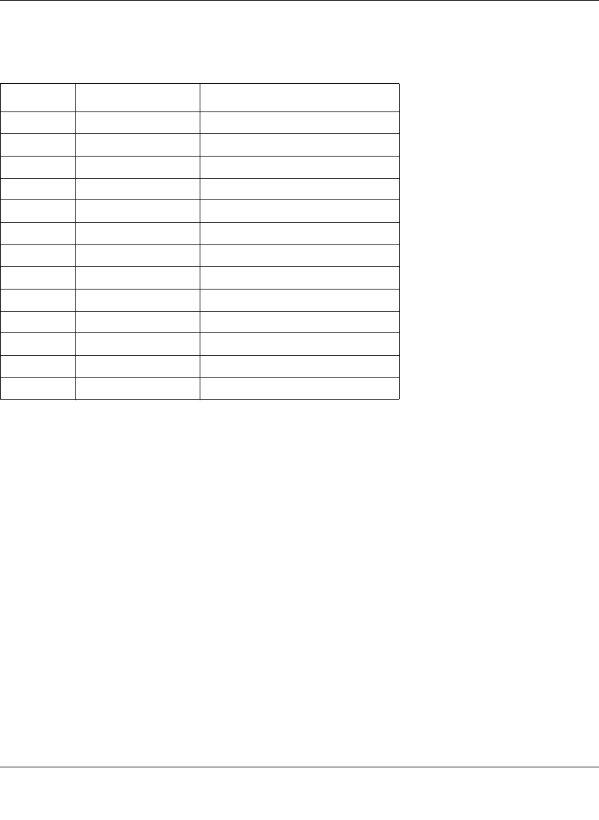
Reference Manual for the Model CG814W Wireless Cable Modem Gateway
Networks, Routing, and Firewall Basics B-19
The radio frequency channels used are listed in Table 6-1:
Note: The available channels supported by the wireless products in various countries are different.
The preferred channel separation between the channels in neighboring wireless networks is 25
MHz (5 channels). This means that you can apply up to three different channels within your
wireless network. There are only 11 usable wireless channels in the United States. It is
recommended that you start using channel 1 and grow to use channel 6, and 11 when necessary, as
these three channels do not overlap.
Table 6-1. 802.11 Radio Frequency Channels
Channel Center Frequency Frequency Spread
1 2412 MHz 2399.5 MHz - 2424.5 MHz
2 2417 MHz 2404.5 MHz - 2429.5 MHz
3 2422 MHz 2409.5 MHz - 2434.5 MHz
4 2427 MHz 2414.5 MHz - 2439.5 MHz
5 2432 MHz 2419.5 MHz - 2444.5 MHz
6 2437 MHz 2424.5 MHz - 2449.5 MHz
7 2442 MHz 2429.5 MHz - 2454.5 MHz
8 2447 MHz 2434.5 MHz - 2459.5 MHz
9 2452 MHz 2439.5 MHz - 2464.5 MHz
10 2457 MHz 2444.5 MHz - 2469.5 MHz
11 2462 MHz 2449.5 MHz - 2474.5 MHz
12 2467 MHz 2454.5 MHz - 2479.5 MHz
13 2472 MHz 2459.5 MHz - 2484.5 MHz
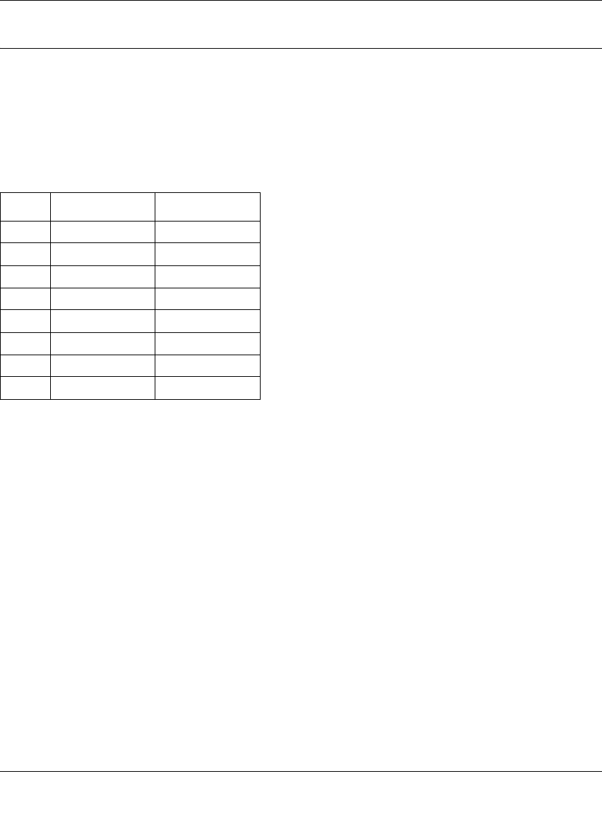
Reference Manual for the Model CG814W Wireless Cable Modem Gateway
B-20 Networks, Routing, and Firewall Basics
Ethernet Cabling
Although Ethernet networks originally used thick or thin coaxial cable, most installations currently
use unshielded twisted pair (UTP) cabling. The UTP cable contains eight conductors, arranged in
four twisted pairs, and terminated with an RJ45 type connector. A normal "straight-through" UTP
Ethernet cable follows the EIA568B standard wiring as described in Table 6-2.
Uplink Switches and Crossover Cables
In the wiring table, the concept of transmit and receive are from the perspective of the PC. For
example, the PC transmits on pins 1 and 2. At the hub, the perspective is reversed, and the hub
receives on pins 1 and 2. When connecting a PC to a PC, or a hub port to another hub port, the
transmit pair must be exchanged with the receive pair. This exchange is done by one of two
mechanisms. Most hubs provide an Uplink switch which will exchange the pairs on one port,
allowing that port to be connected to another hub using a normal Ethernet cable. The second
method is to use a crossover cable, which is a special cable in which the transmit and receive pairs
are exchanged at one of the two cable connectors. Crossover cables are often unmarked as such,
and must be identified by comparing the two connectors. Since the cable connectors are clear
plastic, it is easy to place them side by side and view the order of the wire colors on each. On a
straight-through cable, the color order will be the same on both connectors. On a crossover cable,
the orange and blue pairs will be exchanged from one connector to the other.
Table 6-2. UTP Ethernet cable wiring, straight-through
Pin Wire color Signal
1Orange/White Transmit (Tx) +
2Orange Transmit (Tx) -
3Green/White Receive (Rx) +
4Blue
5Blue/White
6Green Receive (Rx) -
7Brown/White
8Brown

Reference Manual for the Model CG814W Wireless Cable Modem Gateway
Networks, Routing, and Firewall Basics B-21
Cable Quality
A twisted pair Ethernet network operating at 10 Mbits/second (10BASE-T) will often tolerate low
quality cables, but at 100 Mbits/second (10BASE-Tx) the cable must be rated as Category 5, or
"Cat 5", by the Electronic Industry Association (EIA). This rating will be printed on the cable
jacket. A Category 5 cable will meet specified requirements regarding loss and crosstalk. In
addition, there are restrictions on maximum cable length for both 10 and 100 Mbits/second
networks.

Reference Manual for the Model CG814W Wireless Cable Modem Gateway
B-22 Networks, Routing, and Firewall Basics
Preparing Your Network C-1
Appendix C
Preparing Your Network
This appendix describes how to prepare your network to connect to the Internet through the
CG814W Wireless Cable Modem Gateway and how to verify the readiness of broadband Internet
service from an Internet service provider (ISP).
Preparing Your Computers for TCP/IP Networking
Computers access the Internet using a protocol called TCP/IP (Transmission Control Protocol/
Internet Protocol). Each computer on your network must have TCP/IP installed and selected as its
networking protocol. If a Network Interface Card (NIC) is already installed in your PC, then TCP/
IP is probably already installed as well.
Most operating systems include the software components you need for networking with TCP/IP:
•Windows
® 95 or later includes the software components for establishing a TCP/IP network.
• Windows 3.1 does not include a TCP/IP component. You need to purchase a third-party TCP/
IP application package such as NetManage Chameleon.
• Macintosh Operating System 7 or later includes the software components for establishing a
TCP/IP network.
• All versions of UNIX or Linux include TCP/IP components. Follow the instructions provided
with your operating system or networking software to install TCP/IP on your computer.
Note: If an ISP technician configured your computer during the installation of a
broadband modem, or if you configured it using instructions provided by your ISP, you
may need to copy the current configuration information for use in the configuration of
your gateway. Write down this information before reconfiguring your computers. Refer
to “Obtaining ISP Configuration Information for Windows Computers” on page C-20 or
“Obtaining ISP Configuration Information for Macintosh Computers” on page C-21 for
further information.

Reference Manual for the Model CG814W Wireless Cable Modem Gateway
C-2 Preparing Your Network
In your IP network, each PC and the gateway must be assigned a unique IP addresses. Each PC
must also have certain other IP configuration information such as a subnet mask (netmask), a
domain name server (DNS) address, and a default gateway address. In most cases, you should
install TCP/IP so that the PC obtains its specific network configuration information automatically
from a DHCP server during bootup. For a detailed explanation of the meaning and purpose of
these configuration items, refer to Appendix B, “Networks, Routing, and Firewall Basics.”
The CG814W Gateway is shipped preconfigured as a DHCP server. The gateway assigns the
following TCP/IP configuration information automatically when the PCs are rebooted:
• PC or workstation IP addresses—192.168.0.2 through 192.168.0.254
• Subnet mask—255.255.255.0
• Gateway address (the gateway)—192.168.0.1
These addresses are part of the IETF-designated private address range for use in private networks.
Configuring Windows 95, 98, and Me for TCP/IP Networking
As part of the PC preparation process, you need to manually install and configure TCP/IP on each
networked PC. Before starting, locate your Windows CD; you may need to insert it during the
TCP/IP installation process.
Install or Verify Windows Networking Components
To install or verify the necessary components for IP networking:
1. On the Windows taskbar, click the Start button, point to Settings, and then click Control Panel.
2. Double-click the Network icon.
The Network window opens, which displays a list of installed components:

Reference Manual for the Model CG814W Wireless Cable Modem Gateway
Preparing Your Network C-3
You must have an Ethernet adapter, the TCP/IP protocol, and Client for Microsoft Networks.
If you need to install a new adapter, follow these steps:
a. Click the Add button.
b. Select Adapter, and then click Add.
c. Select the manufacturer and model of your Ethernet adapter, and then click OK.
If you need TCP/IP:
a. Click the Add button.
b. Select Protocol, and then click Add.
c. Select Microsoft.
d. Select TCP/IP, and then click OK.
Note: It is not necessary to remove any other network components shown in the
Network window in order to install the adapter, TCP/IP, or Client for Microsoft
Networks.

Reference Manual for the Model CG814W Wireless Cable Modem Gateway
C-4 Preparing Your Network
If you need Client for Microsoft Networks:
a. Click the Add button.
b. Select Client, and then click Add.
c. Select Microsoft.
d. Select Client for Microsoft Networks, and then click OK.
3. Restart your PC for the changes to take effect.
Enabling DHCP in Windows 95B, 98, and Me
After the TCP/IP protocol components are installed, each PC must be assigned specific
information about itself and resources that are available on its network. The simplest way to
configure this information is to allow the PC to obtain the information from a DHCP server in the
network.
You will find there are many similarities in the procedures for different Windows systems
when using DHCP to configure TCP/IP.
The following steps will walk you through the configuration process for each of these
versions of Windows.
Locate your Network Neighborhood icon.
• If the Network Neighborhood icon is on the Windows desktop, position your mouse
pointer over it and right-click your mouse button.
• If the icon is not on the desktop,
— Click Start on the task bar located at the bottom left of the window.
— Choose Settings, and then Control Panel.
— Locate the Network Neighborhood icon and click on it. This will open the Network
panel as shown below.
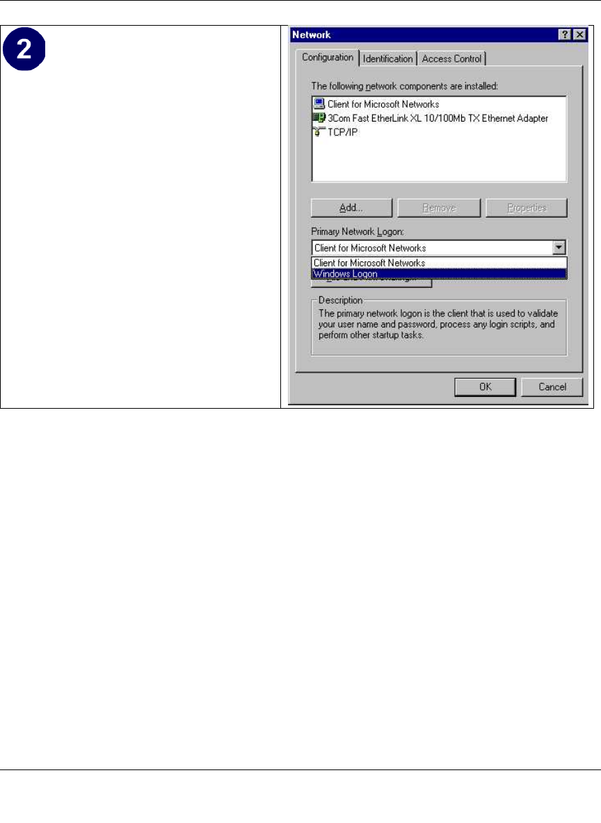
Reference Manual for the Model CG814W Wireless Cable Modem Gateway
Preparing Your Network C-5
Verify the following settings as shown:
• Client for Microsoft Network exists
• Ethernet adapter is present
• TCP/IP is present
•Primary Network Logon is set to
Windows logon
Click on the Properties button. The
following TCP/IP Properties window will
display.
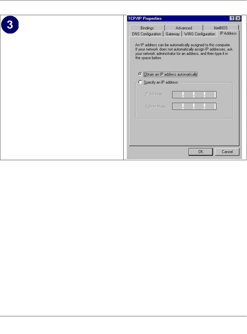
Reference Manual for the Model CG814W Wireless Cable Modem Gateway
C-6 Preparing Your Network
Selecting Windows’ Internet Access Method
1. On the Windows taskbar, click the Start button, point to Settings, and then click Control Panel.
2. Double-click the Internet Options icon.
3. Select “I want to set up my Internet connection manually” or “I want to connect through a
Local Area Network” and click Next.
4. Select “I want to connect through a Local Area Network” and click Next.
5. Uncheck all boxes in the LAN Internet Configuration screen and click Next.
6. Proceed to the end of the Wizard.
Verifying TCP/IP Properties
After your PC is configured and has rebooted, you can check the TCP/IP configuration using the
utility winipcfg.exe:
1. On the Windows taskbar, click the Start button, and then click Run.
By default, the IP Address tab is open on
this window. Verify the following:
•Obtain an IP address automatically is
selected. If not selected, click in the
radio button to the left of it to select it.
This setting is required to enable the
DHCP server to automatically assign an
IP address.
• Click OK to continue.
• Restart the PC.
Repeat these steps for each PC with this
version of Windows on your network.

Reference Manual for the Model CG814W Wireless Cable Modem Gateway
Preparing Your Network C-7
2. Type winipcfg, and then click OK.
The IP Configuration window opens, which lists (among other things), your IP address, subnet
mask, and default gateway.
3. From the drop-down box, select your Ethernet adapter.
The window is updated to show your settings, which should match the values below if you are
using the default TCP/IP settings that NETGEAR recommends for connecting through a
router or gateway:
• The IP address is between 192.168.0.2 and 192.168.0.254
• The subnet mask is 255.255.255.0
• The default gateway is 192.168.0.1
Configuring Windows NT4, 2000 or XP for IP Networking
As part of the PC preparation process, you may need to install and configure
TCP/IP on each networked PC. Before starting, locate your Windows CD; you may need to insert
it during the TCP/IP installation process.
Install or Verify Windows Networking Components
To install or verify the necessary components for IP networking:
1. On the Windows taskbar, click the Start button, point to Settings, and then click Control Panel.
2. Double-click the Network and Dialup Connections icon.
3. If an Ethernet adapter is present in your PC, you should see an entry for Local Area
Connection. Double-click that entry.
4. Select Properties.
5. Verify that ‘Client for Microsoft Networks’ and ‘Internet Protocol (TCP/IP)’ are present. If
not, select Install and add them.
6. Select ‘Internet Protocol (TCP/IP)’, click Properties, and verify that “Obtain an IP address
automatically is selected.
7. Click OK and close all Network and Dialup Connections windows.
8. Then, restart your PC.
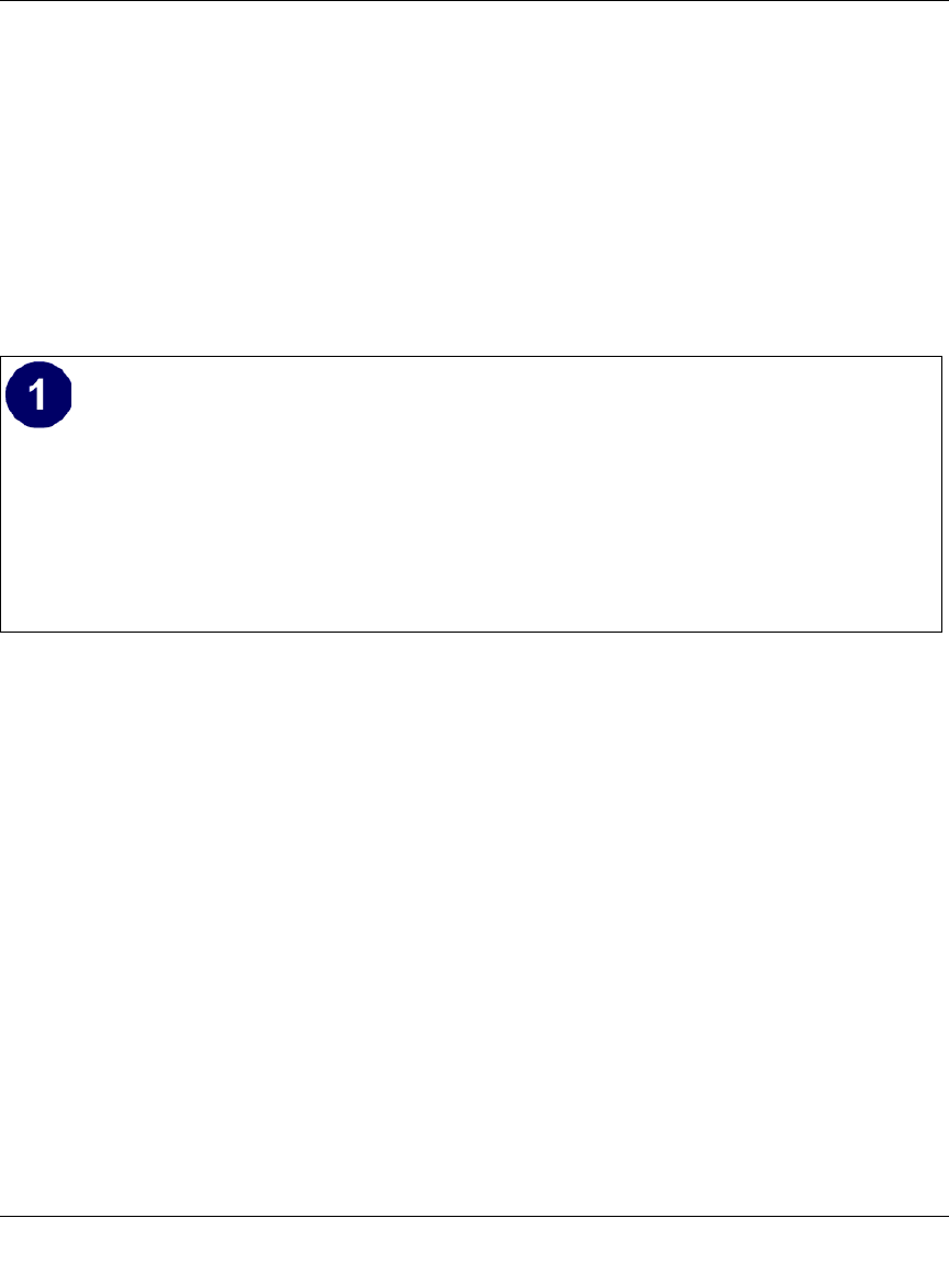
Reference Manual for the Model CG814W Wireless Cable Modem Gateway
C-8 Preparing Your Network
DHCP Configuration of TCP/IP in Windows XP, 2000, or NT4
You will find there are many similarities in the procedures for different Windows systems when
using DHCP to configure TCP/IP.
The following steps will walk you through the configuration process for each of these versions of
Windows.
DHCP Configuration of TCP/IP in Windows XP
Locate your Network Neighborhood icon.
• Select Control Panel from the Windows XP new Start Menu.
• Select the Network Connections icon on the Control Panel. This will take you to the
next step.
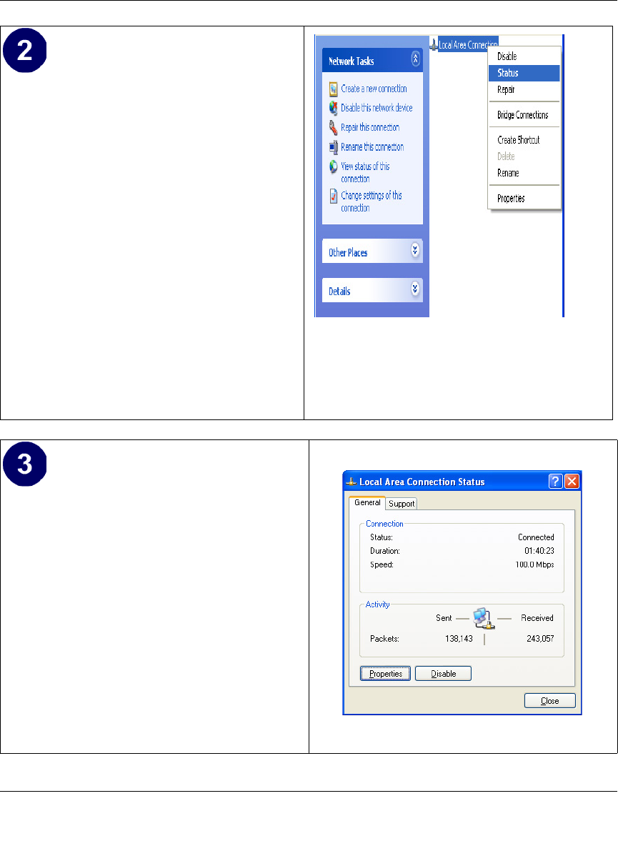
Reference Manual for the Model CG814W Wireless Cable Modem Gateway
Preparing Your Network C-9
Now the Network Connection window
displays. The Connections List that shows
all the network connections set up on the
PC, located to the right of the window.
• Right-click on the Connection with the
wireless icon and choose Status.
Now you should be at the Local Area
Network Connection Status window. This
box displays the connection status, duration,
speed, and activity statistics.
• Administrator logon access rights are
needed to use this window.
• Click the Properties button to view
details about the connection.
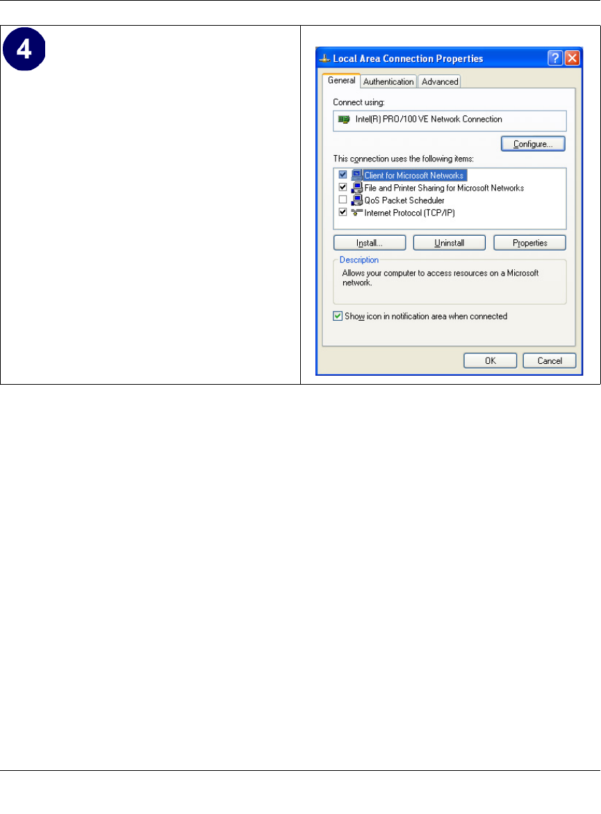
Reference Manual for the Model CG814W Wireless Cable Modem Gateway
C-10 Preparing Your Network
The TCP/IP details are presented on the
Support tab page.
• Select Internet Protocol, and click
Properties to view the configuration
information.
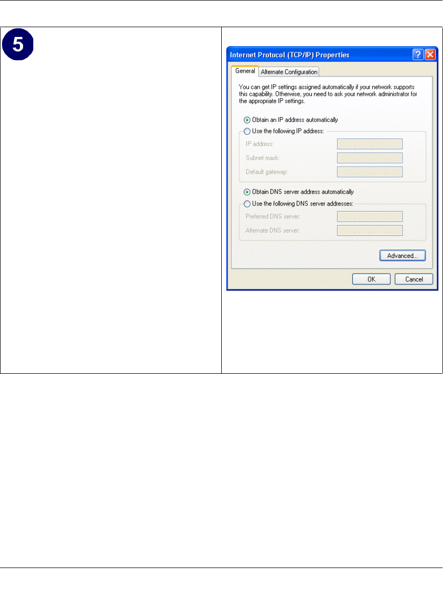
Reference Manual for the Model CG814W Wireless Cable Modem Gateway
Preparing Your Network C-11
DHCP Configuration of TCP/IP in Windows 2000
Once again, after you have installed the network card, TCP/IP for Windows 2000 is configured.
TCP/IP should be added by default and set to DHCP without your having to configure it.
However, if there are problems, you may need to know how to do it manually. Remember, Cox
only sets up TCP/IP dynamically, (i.e., it uses DHCP to obtain TCP/IP settings). Following are the
steps to configure TCP/IP with DHCP for Windows 2000.
Verify that the Obtain an IP address
automatically radio button is selected.
• Verify that Obtain DNS server address
automatically radio button is selected.
• Click the OK button.
This completes the DHCP configuration of
TCP/IP in Windows XP.
Repeat these steps for each PC with this
version of Windows on your network.
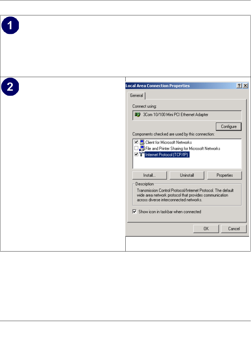
Reference Manual for the Model CG814W Wireless Cable Modem Gateway
C-12 Preparing Your Network
• Click on the My Network Places icon on the Windows desktop. This will bring up a
window called Network and Dial-up Connections.
• Right click on Local Area Connection and select Properties.
The Local Area Connection Properties
dialog box appears.
• Verify that you have the correct Ethernet
card selected in the Connect using: box.
• Verify that at least the following two
items are displayed and selected in the
box of “Components checked are used
by this connection:”
— Client for Microsoft Networks and
— Internet Protocol (TCP/IP)
• Click OK.
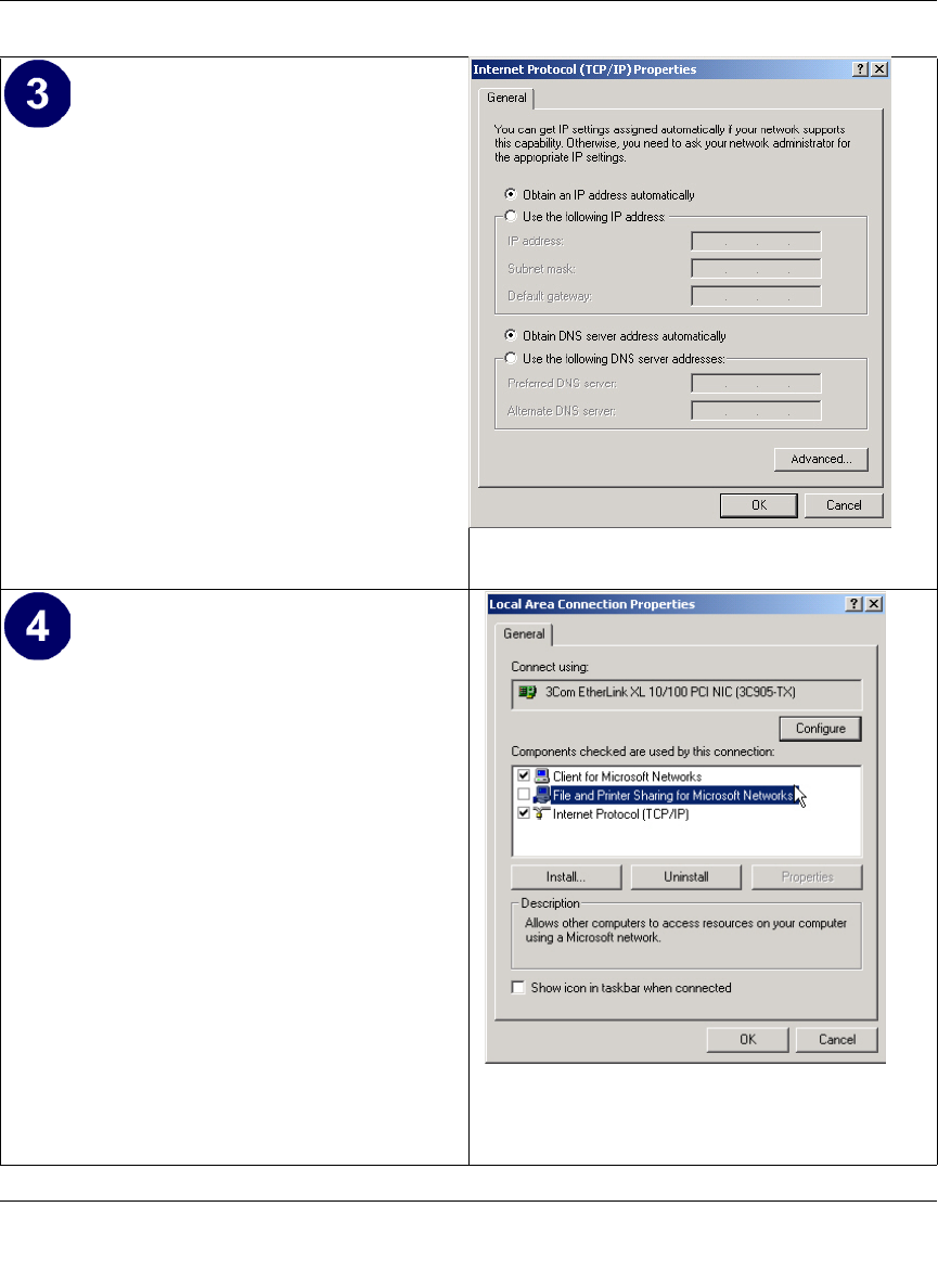
Reference Manual for the Model CG814W Wireless Cable Modem Gateway
Preparing Your Network C-13
• With Internet Protocol (TCP/IP)
selected, click on Properties to open the
Internet Protocol (TCP/IP) Properties
dialogue box. Verify that
–Obtain an IP address
automatically is selected.
–Obtain DNS server address
automatically is selected.
• Click OK to return to Local Area
Connection Properties.
• Click OK again to complete the
configuration process for Windows
2000.
• Restart the PC.
Repeat these steps for each PC with this
version of Windows on your network.
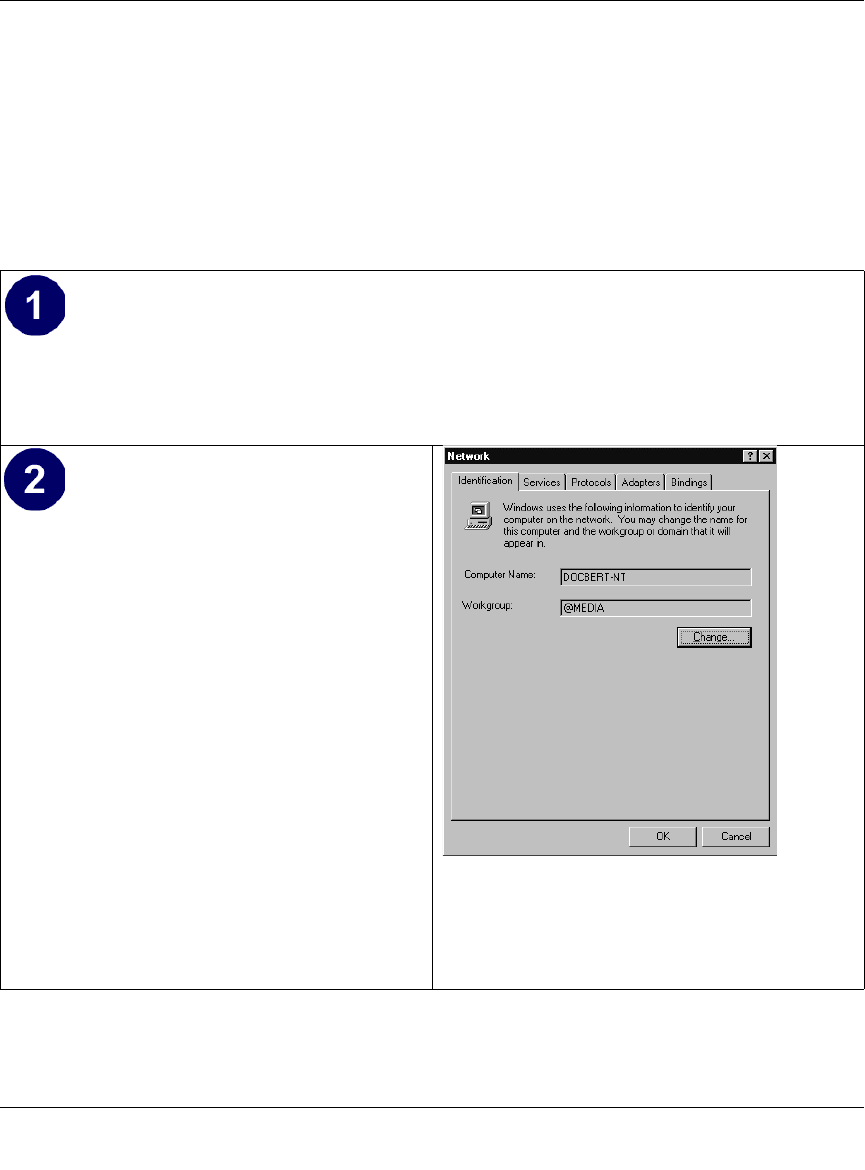
Reference Manual for the Model CG814W Wireless Cable Modem Gateway
C-14 Preparing Your Network
DHCP Configuration of TCP/IP in Windows NT4
Once you have installed the network card, you need to configure the TCP/IP environment for
Windows NT 4.0. Again, remember Cox only sets up TCP/IP dynamically (i.e., it uses DHCP to
obtain TCP/IP settings).
Following are the procedures you use to configure TCP/IP with DHCP in Windows NT 4.0.
• Choose Settings from the Start Menu, and then select Control Panel.
This will display Control Panel window.
• Double-click the Network icon in the
Control Panel window.
The Network panel will display.
• Select the Protocols tab to continue.
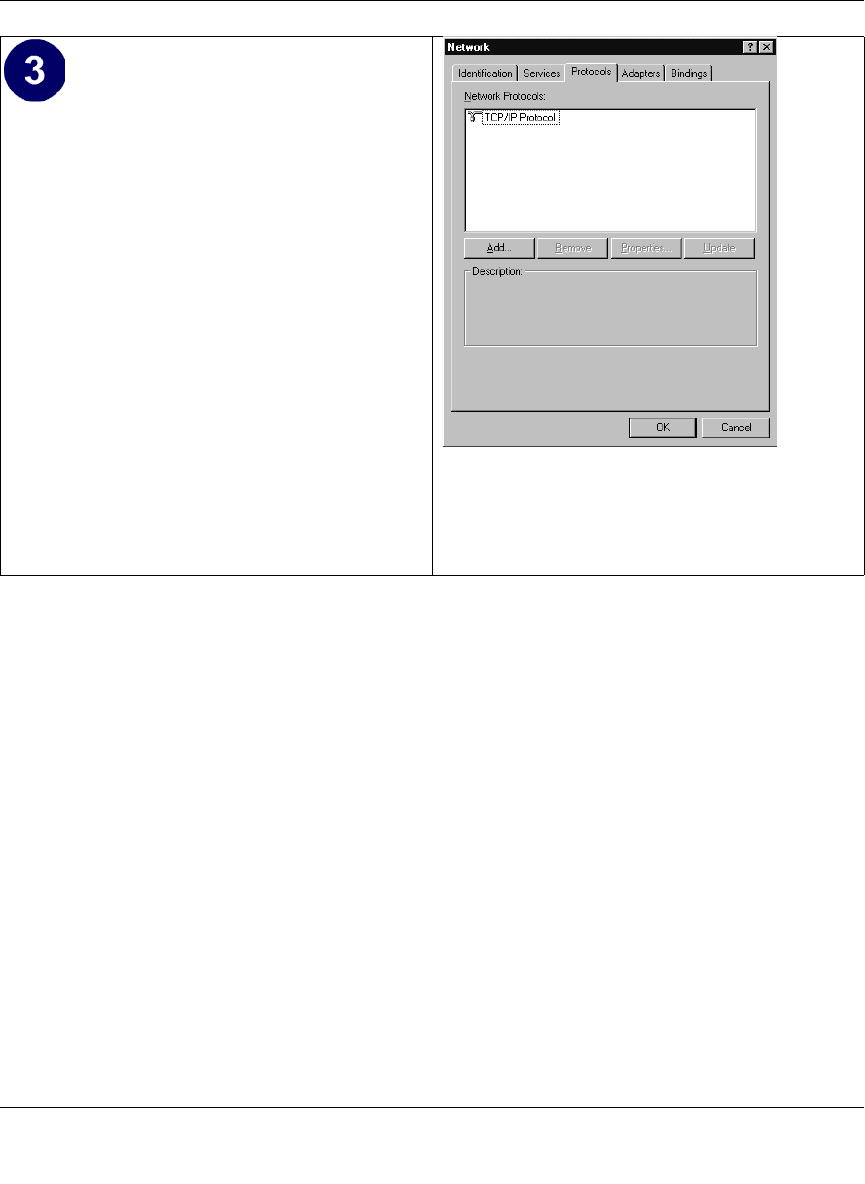
Reference Manual for the Model CG814W Wireless Cable Modem Gateway
Preparing Your Network C-15
• Highlight the TCP/IP Protocol in the
Network Protocols box, and click on
the Properties button.
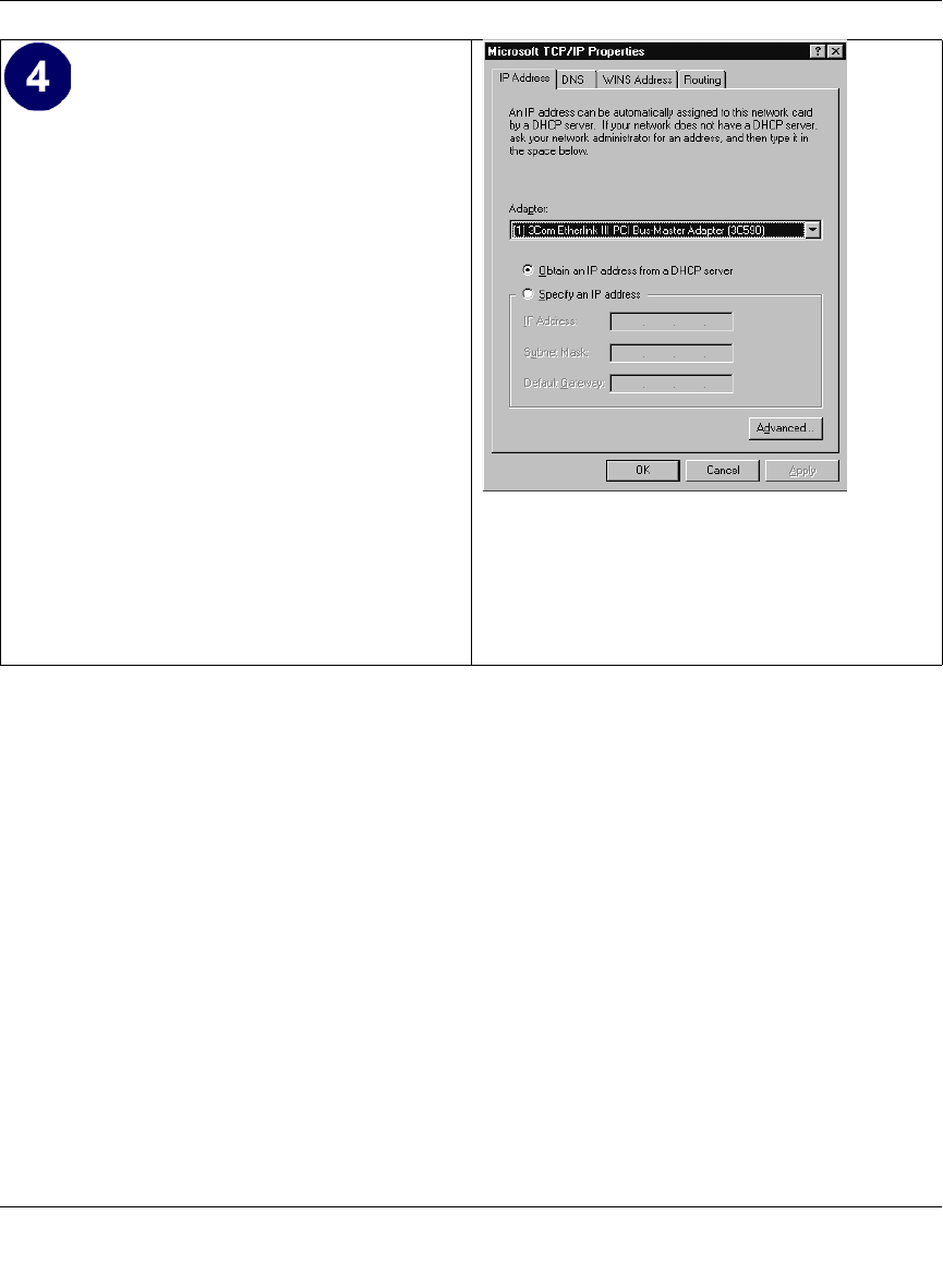
Reference Manual for the Model CG814W Wireless Cable Modem Gateway
C-16 Preparing Your Network
Verifying TCP/IP Properties for Windows XP, 2000, and NT4
To check your PC’s TCP/IP configuration:
1. On the Windows taskbar, click the Start button, and then click Run.
The Run window opens.
2. Type cmd and then click OK.
A command window opens
3. Type ipconfig /all
Your IP Configuration information will be listed, and should match the values below if you are
using the default TCP/IP settings that NETGEAR recommends for connecting through a
router or gateway:
• The IP address is between 192.168.0.2 and 192.168.0.254
• The subnet mask is 255.255.255.0
The TCP/IP Properties dialog box now
displays.
• Click the IP Address tab.
• Select the radio button marked Obtain
an IP address from a DHCP server.
• Click OK. This completes the
configuration of TCP/IP in Windows
NT.
Restart the PC.
Repeat these steps for each PC with this
version of Windows on your network.
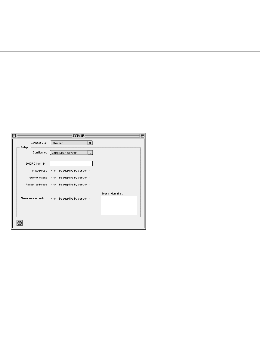
Reference Manual for the Model CG814W Wireless Cable Modem Gateway
Preparing Your Network C-17
• The default gateway is 192.168.0.1
4. Type exit
Configuring the Macintosh for TCP/IP Networking
Beginning with Macintosh Operating System 7, TCP/IP is already installed on the Macintosh. On
each networked Macintosh, you will need to configure TCP/IP to use DHCP.
MacOS 8.6 or 9.x
1. From the Apple menu, select Control Panels, then TCP/IP.
The TCP/IP Control Panel opens:
2. From the “Connect via” box, select your Macintosh’s Ethernet interface.
3. From the “Configure” box, select Using DHCP Server.
You can leave the DHCP Client ID box empty.
4. Close the TCP/IP Control Panel.
5. Repeat this for each Macintosh on your network.
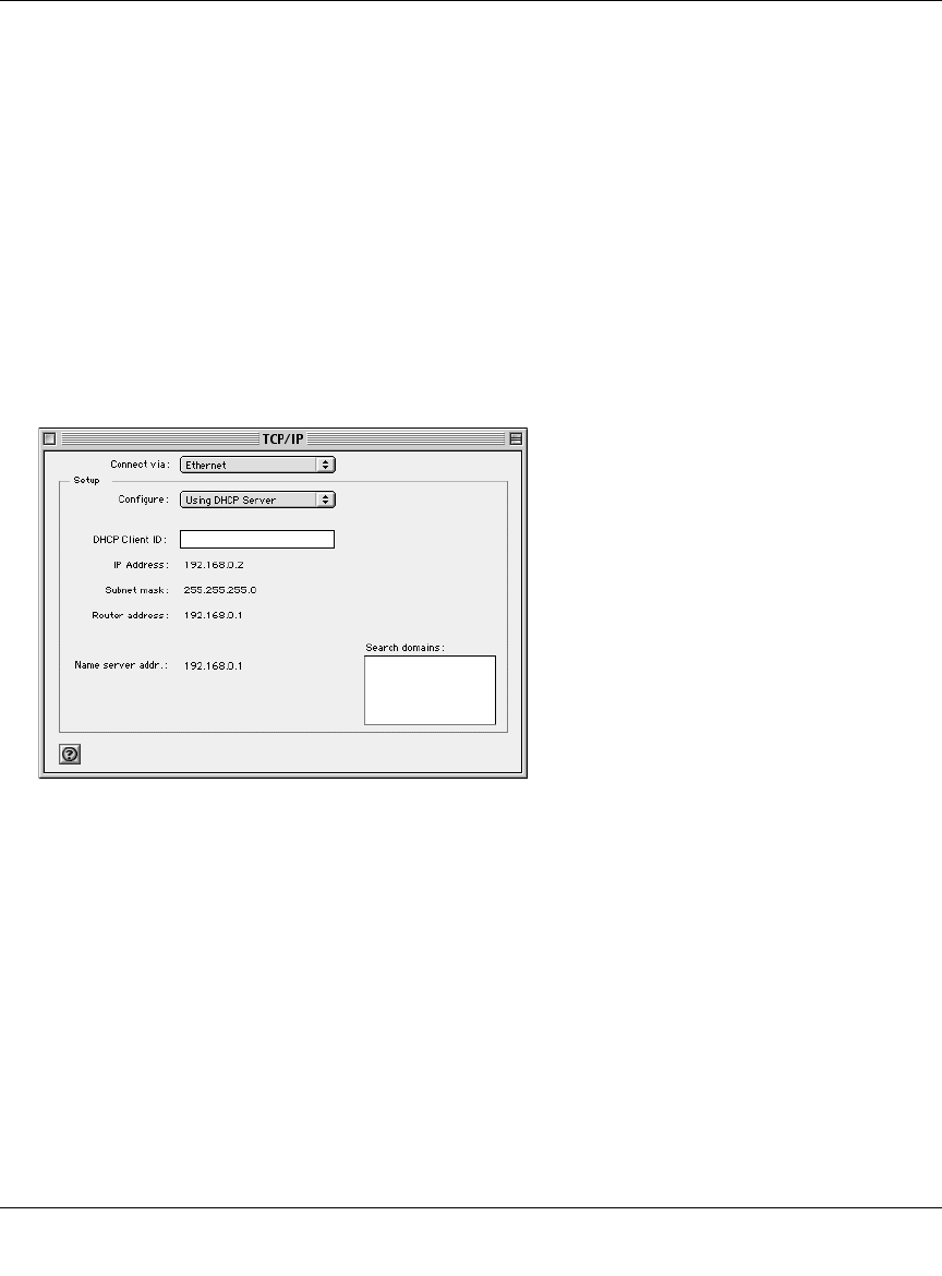
Reference Manual for the Model CG814W Wireless Cable Modem Gateway
C-18 Preparing Your Network
MacOS X
1. From the Apple menu, choose System Preferences, then Network.
2. If not already selected, select Built-in Ethernet in the Configure list.
3. If not already selected, Select Using DHCP in the TCP/IP tab.
4. Click Save.
Verifying TCP/IP Properties for Macintosh Computers
After your Macintosh is configured and has rebooted, you can check the TCP/IP configuration by
returning to the TCP/IP Control Panel. From the Apple menu, select Control Panels, then TCP/IP.
The panel is updated to show your settings, which should match the values below if you are using
the default TCP/IP settings that NETGEAR recommends:
• The IP Address is between 192.168.0.2 and 192.168.0.254
• The Subnet mask is 255.255.255.0
• The Router address is 192.168.0.1
If you do not see these values, you may need to restart your Macintosh or you may need to switch
the “Configure” setting to a different option, then back again to “Using DHCP Server”.

Reference Manual for the Model CG814W Wireless Cable Modem Gateway
Preparing Your Network C-19
Verifying the Readiness of Your Internet Account
For broadband access to the Internet, you need to contract with an Internet service provider (ISP)
for a single-user Internet access account using a cable modem or DSL modem. This modem must
be a separate physical box (not a card) and must provide an Ethernet port intended for connection
to a Network Interface Card (NIC) in a computer. Your gateway does not support a
USB-connected broadband modem.
For a single-user Internet account, your ISP supplies TCP/IP configuration information for one
computer. With a typical account, much of the configuration information is dynamically assigned
when your PC is first booted up while connected to the ISP, and you will not need to know that
dynamic information.
In order to share the Internet connection among several computers, your gateway takes the place of
the single PC, and you need to configure it with the TCP/IP information that the single PC would
normally use. When the gateway’s Internet port is connected to the broadband modem, the
gateway appears to be a single PC to the ISP. The gateway then allows the PCs on the local
network to masquerade as the single PC to access the Internet through the broadband modem. The
method used by the gateway to accomplish this is called Network Address Translation (NAT) or IP
masquerading.
Are Login Protocols Used?
Some ISPs require a special login protocol, in which you must enter a login name and password in
order to access the Internet. If you normally log in to your Internet account by running a program
such as WinPOET or EnterNet, then your account uses PPP over Ethernet (PPPoE).
When you configure your router, you will need to enter your login name and password in the
router’s configuration menus. After your network and gateway are configured, the gateway will
perform the login task when needed, and you will no longer need to run the login program from
your PC. It is not necessary to uninstall the login program.
What Is Your Configuration Information?
More and more, ISPs are dynamically assigning configuration information. However, if your ISP
does not dynamically assign configuration information but instead used fixed configurations, your
ISP should have given you the following basic information for your account:

Reference Manual for the Model CG814W Wireless Cable Modem Gateway
C-20 Preparing Your Network
• An IP address and subnet mask
• A gateway IP address, which is the address of the ISP’s router
• One or more domain name server (DNS) IP addresses
• Host name and domain suffix
For example, your account’s full server names may look like this:
mail.xxx.yyy.com
In this example, the domain suffix is xxx.yyy.com.
If any of these items are dynamically supplied by the ISP, your gateway automatically acquires
them.
If an ISP technician configured your PC during the installation of the broadband modem, or if you
configured it using instructions provided by your ISP, you need to copy the configuration
information from your PC’s Network TCP/IP Properties window or Macintosh TCP/IP Control
Panel before reconfiguring your PC for use with the gateway. These procedures are described next.
Obtaining ISP Configuration Information for Windows Computers
As mentioned above, you may need to collect configuration information from your PC so that you
can use this information when you configure the CG814W Gateway. Following this procedure is
only necessary when your ISP does not dynamically supply the account information.
To get the information you need to configure the gateway for Internet access:
1. On the Windows taskbar, click the Start button, point to Settings, and then click Control Panel.
2. Double-click the Network icon.
The Network window opens, which displays a list of installed components.
3. Select TCP/IP, and then click Properties.
The TCP/IP Properties dialog box opens.
4. Select the IP Address tab.
If an IP address and subnet mask are shown, write down the information. If an address is
present, your account uses a fixed (static) IP address. If no address is present, your account
uses a dynamically-assigned IP address. Click “Obtain an IP address automatically”.
5. Select the Gateway tab.

Reference Manual for the Model CG814W Wireless Cable Modem Gateway
Preparing Your Network C-21
If an IP address appears under Installed Gateways, write down the address. This is the ISP’s
gateway address. Select the address and then click Remove to remove the gateway address.
6. Select the DNS Configuration tab.
If any DNS server addresses are shown, write down the addresses. If any information appears
in the Host or Domain information box, write it down. Click Disable DNS.
7. Click OK to save your changes and close the TCP/IP Properties dialog box.
You are returned to the Network window.
8. Click OK.
9. Reboot your PC at the prompt. You may also be prompted to insert your Windows CD.
Obtaining ISP Configuration Information for Macintosh
Computers
As mentioned above, you may need to collect configuration information from your Macintosh so
that you can use this information when you configure the CG814W Gateway. Following this
procedure is only necessary when your ISP does not dynamically supply the account information.
To get the information you need to configure the gateway for Internet access:
1. From the Apple menu, select Control Panels, then TCP/IP.
The TCP/IP Control Panel opens, which displays a list of configuration settings. If the
“Configure” setting is “Using DHCP Server”, your account uses a dynamically-assigned IP
address. In this case, close the Control Panel and skip the rest of this section.
2. If an IP address and subnet mask are shown, write down the information.
3. If an IP address appears under Router address, write down the address. This is the ISP’s
gateway address.
4. If any Name Server addresses are shown, write down the addresses. These are your ISP’s DNS
addresses.
5. If any information appears in the Search domains information box, write it down.
6. Change the “Configure” setting to “Using DHCP Server”.
7. Close the TCP/IP Control Panel.

Reference Manual for the Model CG814W Wireless Cable Modem Gateway
C-22 Preparing Your Network
Restarting the Network
Once you’ve set up your computers to work with the gateway, you must reset the network for the
devices to be able to communicate correctly. Restart any computer that is connected to the firewall.
After configuring all of your computers for TCP/IP networking and restarting them, and
connecting them to the local network of your CG814W Gateway, you are ready to access and
configure the gateway.

Reference Manual for the Model CG814W Wireless Cable Modem Gateway
Glossary 1
Glossary
10BASE-T IEEE 802.3 specification for 10 Mbps Ethernet over twisted pair wiring.
100BASE-Tx IEEE 802.3 specification for 100 Mbps Ethernet over twisted pair wiring.
802.11b IEEE specification for wireless networking at 11 Mbps using direct-sequence
spread-spectrum (DSSS) technology and operating in the unlicensed radio
spectrum at 2.5GHz.
Denial of Service
attack DoS. A hacker attack designed to prevent your computer or network from
operating or communicating.
DHCP See Dynamic Host Configuration Protocol.
DNS See Domain Name Server.
domain name A descriptive name for an address or group of addresses on the Internet.
Domain names are of the form of a registered entity name plus one of a
number of predefined top level suffixes such as .com, .edu, .uk, etc. For
example, in the address mail.NETGEAR.com, mail is a server name and
NETGEAR.com is the domain.
DOCSIS Data Over Cable Service Interface Specification. Defines interface
requirements for cable modems involved in high-speed data distribution over
cable television system networks
Domain Name Server A Domain Name Server (DNS) resolves descriptive names of network
resources (such as www.NETGEAR.com) to numeric IP addresses.
Dynamic Host
Configuration
Protocol
DHCP. An Ethernet protocol specifying how a centralized DHCP server can
assign network configuration information to multiple DHCP clients. The
assigned information includes IP addresses, DNS addresses, and gateway
(router) addresses.

Reference Manual for the Model CG814W Wireless Cable Modem Gateway
2Glossary
Gateway A local device, usually a router, that connects hosts on a local network to other
networks.
IETF Internet Engineering Task Force. An open international community of
network designers, operators, vendors, and researchers concerned with the
evolution of the Internet architecture and the smooth operation of the Internet.
Working groups of the IETF propose standard protocols and procedures for
the Internet, which are published as RFCs (Request for Comment) at
www.ietf.org.
IP Internet Protocol. The main internetworking protocol used in the Internet.
Used in conjunction with the Transfer Control Protocol (TCP) to form TCP/IP.
IP Address A four-position number uniquely defining each host on the Internet. Ranges of
addresses are assigned by Internic, an organization formed for this purpose.
Usually written in dotted-decimal notation with periods separating the bytes
(for example, 134.177.244.57).
IPSec Internet Protocol Security. IPSec is a series of guidelines for securing private
information transmitted over public networks. IPSec is a VPN method
providing a higher level of security than PPTP.
ISP Internet service provider.
LAN See local area network.
local area network LAN. A communications network serving users within a limited area, such as
one floor of a building. A LAN typically connects multiple personal
computers and shared network devices such as storage and printers. Although
many technologies exist to implement a LAN, Ethernet is the most common
for connecting personal computers.
MAC address Media Access Control address. A unique 48-bit hardware address assigned to
every Ethernet node. Usually written in the form 01:23:45:67:89:ab.
Mbps Megabits per second.
MSB See Most Significant Bit or Most Significant Byte.
MTU See Maximum Transmit Unit.
Maximum Transmit
Unit The size in bytes of the largest packet that can be sent or received.
Most Significant Bit or
Most Significant Byte The portion of a number, address, or field that is farthest left when written as a
single number in conventional hexadecimal ordinary notation. The part of the
number having the most value.

Reference Manual for the Model CG814W Wireless Cable Modem Gateway
Glossary 3
NAT See Network Address Translation.
netmask A number that explains which part of an IP address comprises the network
address and which part is the host address on that network. It can be
expressed in dotted-decimal notation or as a number appended to the IP
address. For example, a 28-bit mask starting from the MSB can be shown as
255.255.255.192 or as /28 appended to the IP address.
Network Address
Translation A technique by which several hosts share a single IP address for access to the
Internet.
packet A block of information sent over a network. A packet typically contains a
source and destination network address, some protocol and length
information, a block of data, and a checksum.
PPP See Point-to-Point Protocol.
PPTP Point-to-Point Tunneling Protocol. A method for establishing a virtual private
network (VPN) by embedding Microsoft’s network protocol into Internet
packets.
Point-to-Point
Protocol PPP. A protocol allowing a computer using TCP/IP to connect directly to the
Internet.
RFC Request For Comment. Refers to documents published by the Internet
Engineering Task Force (IETF) proposing standard protocols and procedures
for the Internet. RFCs can be found at www.ietf.org.
RIP See Routing Information Protocol.
router A device that forwards data between networks. An IP router forwards data
based on IP source and destination addresses.
Routing Information
Protocol A protocol in which routers periodically exchange information with one
another so that they can determine minimum distance paths between sources
and destinations.
subnet mask See netmask.
URL Universal Resource Locator, the global address of documents and other
resources on the World Wide Web.
UTP Unshielded twisted pair. The cable used by 10BASE-T and 100BASE-Tx
Ethernet networks.

Reference Manual for the Model CG814W Wireless Cable Modem Gateway
4Glossary
VPN Virtual Private Network. A method for securely transporting data between two
private networks by using a public network such as the Internet as a
connection.
WAN See wide area network.
WEP Wired Equivalent Privacy. WEP is a data encryption protocol for 802.11b
wireless networks. All wireless nodes and access points on the network are
configured with a 64-bit or 128-bit Shared Key for data encryption.
wide area network WAN. A long distance link used to extend or connect remotely located local
area networks. The Internet is a large WAN.
Windows Internet
Naming Service WINS. Windows Internet Naming Service is a server process for resolving
Windows-based computer names to IP addresses. If a remote network
contains a WINS server, your Windows PCs can gather information from that
WINS server about its local hosts. This allows your PCs to browse that remote
network using Network Neighborhood.
WINS See Windows Internet Naming Service.
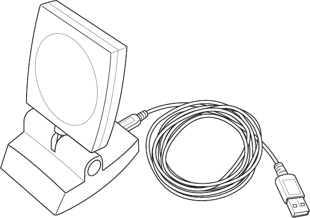
ASUS WLAN mini-PCI card
WL-120
User Manual

2ASUS WLAN mini-PCI card
No part of this manual, including the products and software described in it,
may be reproduced, transmitted, transcribed, stored in a retrieval system,
or translated into any language in any form or by any means, except docu-
mentation kept by the purchaser for backup purposes, without the express
written permission of ASUSTeK COMPUTER INC. (“ASUS”).
ASUS PROVIDES THIS MANUAL “AS IS” WITHOUT WARRANTY
OF ANY KIND, EITHER EXPRESS OR IMPLIED, INCLUDING BUT
NOT LIMITED TO THE IMPLIED WARRANTIES OR CONDITIONS
OF MERCHANTABILITY OR FITNESS FOR A PARTICULAR PUR-
POSE. IN NO EVENT SHALL ASUS, ITS DIRECTORS, OFFICERS,
EMPLOYEES OR AGENTS BE LIABLE FOR ANY INDIRECT, SPE-
CIAL, INCIDENTAL, OR CONSEQUENTIAL DAMAGES (INCLUD-
ING DAMAGES FOR LOSS OF PROFITS, LOSS OF BUSINESS, LOSS
OF USE OR DATA, INTERRUPTION OF BUSINESS AND THE LIKE),
EVEN IF ASUS HAS BEEN ADVISED OF THE POSSIBILITY OF SUCH
DAMAGES ARISING FROM ANY DEFECT OR ERROR IN THIS
MANUAL OR PRODUCT.
Product warranty or service will not be extended if: (1) the product is re-
paired, modified or altered, unless such repair, modification of alteration is
authorized in writing by ASUS; or (2) the serial number of the product is
defaced or missing.
Products and corporate names appearing in this manual may or may not be
registered trademarks or copyrights of their respective companies, and are
used only for identification or explanation and to the owners’ benefit, without
intent to infringe.
SPECIFICATIONS AND INFORMATION CONTAINED IN THIS
MANUAL ARE FURNISHED FOR INFORMATIONAL USE ONLY, AND
ARE SUBJECT TO CHANGE AT ANY TIME WITHOUT NOTICE, AND
SHOULD NOT BE CONSTRUED AS A COMMITMENT BY ASUS. ASUS
ASSUMES NO RESPONSIBILITY OR LIABILITY FOR ANY ERRORS
OR INACCURACIES THAT MAY APPEAR IN THIS MANUAL, IN-
CLUDING THE PRODUCTS AND SOFTWARE DESCRIBED IN IT.
Copyright © 2003 ASUSTeK COMPUTER INC. All Rights Reserved.
Copyright Information
Product Name: ASUS WLAN mini-PCI card (WL-120)
Manual Revision: 1 E1219
Release Date: March 2003

ASUS WLAN mini-PCI card 3
Copyright Information
ASUSTeK COMPUTER INC. (Asia-Pacific)
Address: 150 Li-Te Road, Peitou, Taipei, Taiwan 112
General Tel: +886-2-2894-3447
General Fax: +886-2-2894-3449
General Email: info@asus.com.tw
Technical Support
MB/Others (Tel):+886-2-2890-7121 (English)
Notebook (Tel): +886-2-2890-7122 (English)
Desktop/Server: +886-2-2890-7123 (English)
Support Fax: +886-2-2890-7698
Support Email: tsd@asus.com.tw
Web Site: www.asus.com.tw
ASUS COMPUTER INTERNATIONAL (America)
Address: 44370 Nobel Drive, Fremont, CA 94538, USA
General Fax: +1-510-608-4555
General Email: tmd1@asus.com
Technical Support
Support Fax: +1-510-608-4555
General Support: +1-502-933-8713
Web Site: www.asus.com
Support Email: tsd@asus.com
ASUS COMPUTER GmbH (Germany & Austria)
Address: Harkortstr. 25, 40880 Ratingen, BRD, Germany
General Fax: +49-2102-442066
General Email: sales@asuscom.de (for marketing requests only)
Technical Support
Support Hotline: MB/Others: +49-2102-9599-0
Notebook (Tel): +49-2102-9599-10
Support Fax: +49-2102-9599-11
Support (Email): www.asuscom.de/de/support (for online support)
Web Site: www.asuscom.de

ASUS WLAN mini-PCI card 4
Quick Start Guide
Chapter 1
Welcome
The ASUS WLAN mini-PCI card is designed to be fully compliant with the
IEEE 802.11b wireless local area network (Wireless LAN) standard. The
ASUS WLAN mini-PCI card comes with two antenna connectors, which
are individually connected to the built-in antennas in your notebook. The
two antennas allow your notebook to have the best communication when
you are enjoying the wireless link.
Verifying the TCP/IP Protocol
Windows 98/Me
Right-click My Network Place on the desktop and select properties.
Scroll down and look for "TCP/IP -> ASUS 802.11b Network Adap-
ter". Make sure that the TCP/IP protocal parameters (IP adress, gate-
way, and subnet mask) are set correctly.
Windows 2K/XP
Open the Control Panel through the Start menu. Double-click Network
Connection icon. Right click " ASUS 802.11b Network Adapter" and sel-
ect Properties. Look for "Internet Protocal (TCP/IP)". Make sure that
the TCP/IP protocal parameters (IP adress, gateway, and subnet mask) are
set correctly.

ASUS WLAN mini-PCI card 5
Quick Start Guide
Chapter 5
Installing the WLAN mini-PCI card Utilities
After you have installed the WLAN mini-PCI card driver, you can install
WLAN mini-PCI card utilities. Refer to the User's manual for detailed
information.
1. Insert the ASUS WLAN mini-PCI card support CD and an autorun
menu will appear. If your autorun is disabled, double click SETUP.EXE
in the root directory of the support CD.
2. From the autorun menu, click Install ASUS WLAN mini-PCI card
Utilities.
3. Follow the on-screen instructions to complete the installation.

ASUS WLAN mini-PCI card 6
Reference
Chapter 3
Software Reference
1. Overview
The ASUS WLAN mini-PCI card software includes five groups of utili-
ties.
•Control Center – Makes it easy to launch applications and activate
network location settings.
• Wireless Settings – Allows users to control the ASUS WLAN mini-PCI
card.
•Mobile Manager – A convenient tool to setup and manage network
location settings.
•Site Monitor – Measures the signal-to-noise (SNR) values of all wire-
less networks. This tool is used for determining the best placement of
Access Points to provide the most efficient coverage in a wireless net-
work.
•Live Update – Provides automatic driver and firmware update through
the Internet.
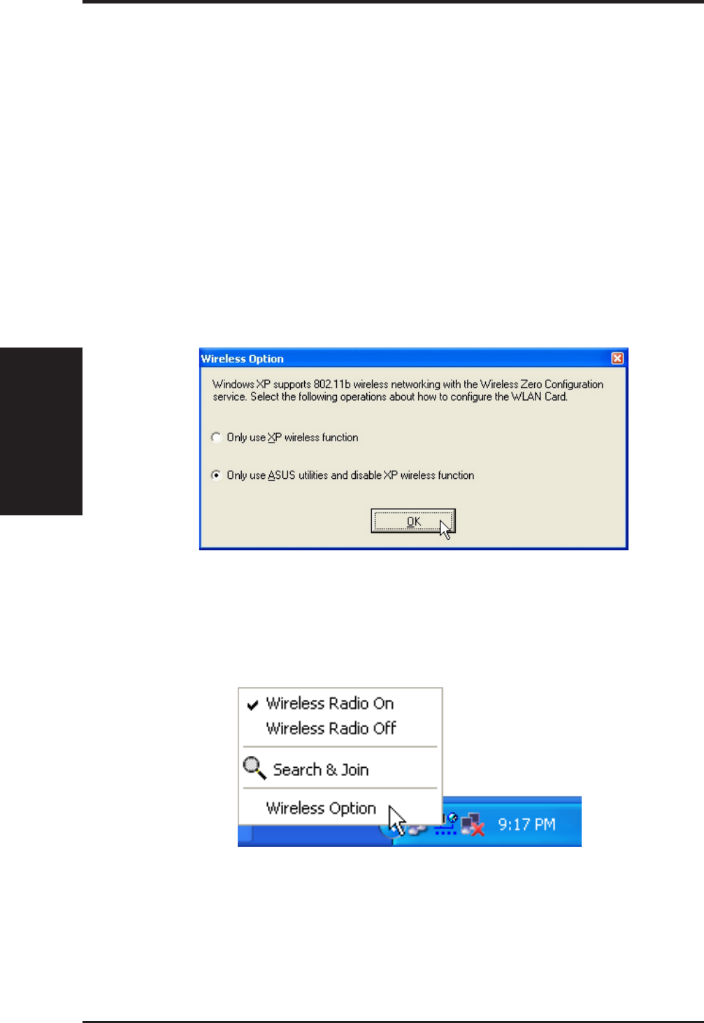
7ASUS WLAN mini-PCI card
Reference
Chapter 3
2. Windows XP Wireless Options
The wireless options shown below is only available for Windows XP. The
first time you run the Control Center utility, it will automatically show.
Select one of the radio buttons to decide your Windows XP wireless net-
working environment.
Only use XP wireless function – Only use Windows XP wireless network
settings to configure the ASUS WLAN mini-PCI card.
Only use ASUS utilities and disable XP wireless function – Only use ASUS
WALN mini-PCI card utilities to configure the ASUS mini-PCI card.
You can return to the Wireless Option setting at any time by left clicking
the control center icon and choosing “Wireless Option”.
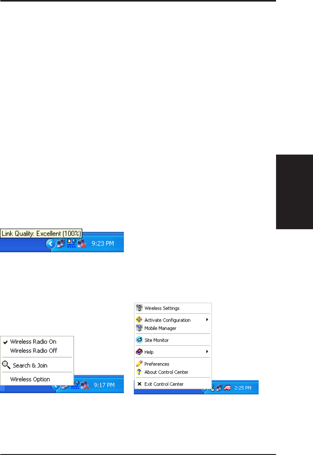
ASUS WLAN mini-PCI card 8
Reference
Chapter 3
3. Control Center
Control Center is an application that makes it easy to launch applications
and activate network location settings. Control Center starts automatically
when the system boots. Whenever Control Center is running, you will see
a Control Center icon displayed on the Windows taskbar.
Starting the Control Center manually
• Click the Windows Start button, select Programs, select ASUS Util-
ity, select WLAN Card, and click ASUS WLAN Control Center.
or
• Double click the Control Center icon on the desktop.
Using the Control Center Taskbar
1. The Control Center Taskbar menu display the following information:
• The link quality of the ASUS WLAN mini-PCI card (Excellent,
Good, Fair, Poor, Not Linked)
• Whether the ASUS WLAN mini-PCI card is connected to the In-
ternet (Blue: Connected, Gray: Not Connected)
Taskbar Right-Click Menu
Taskbar Icon and Status
Taskbar Left-Click Menu
9ASUS WLAN mini-PCI card
Reference
Chapter 3
2. Right-clicking the taskbar icon shows the following menu:
•Wireless Settings – Launches Wireless Settings application.
•Activate Configuration – Allows you to set which profile to use.
•Mobile Manager – Launches Mobile Manager application.
•AP Manager – Launches AP Manager application installed with
the Wireless LAN Utilities.
•Preferences – Customizes the way the Control Center program be-
haves. You can create a Control Center shortcut on the desktop. You
can also set whether Control Center starts up with Windows.
•Exit – Closes the Control Center program.
Wireless Status Icons (on the taskbar)
Excellent link quality and connected to Internet (Infrastructure)
Good link quality and connected to Internet (Infrastructure)
Fair link quality and connected to Internet (Infrastructure)
Poor link quality and connected to Internet (Infrastructure)
Not linked but connected to Internet (Infrastructure)
Excellent link quality but not connected to Internet (Infrastructure)
Good link quality but not connected to Internet (Infrastructure)
Fair link quality but not connected to Internet (Infrastructure)
Poor link quality but not connected to Internet (Infrastructure)
Not linked and not connected to Internet (Infrastructure)
Linked (Ad Hoc)
Not Linked (Ad Hoc)
Connected to Internet

ASUS WLAN mini-PCI card 10
Reference
Chapter 3
3. Left-clicking the taskbar icon shows the following menu:
•Wireless Radio On – Turns the wireless radio ON.
•Wireless Radio Off – Turns the wireless radio OFF.
•Search and Join – View the properties of available Access Points
within range.
•Wireless Option (Windows XP only) – Sets your Windows XP wire-
less networking environment.
4. Double-clicking the taskbar icon:
• Launches the Wireless Settings application.
4. Wireless Settings
Wireless Settings is an application that allows you to control your ASUS
WLAN mini-PCI card. Use Wireless Settings to View or Modify the con-
figuration settings and monitor the operational status of your PC Card.
Once Wireless Settings is launched, you can see the tabbed property sheet.
This property sheet is composed of tabbed “pages”, each with its own group
of feature-specific settings.
Starting Wireless Settings
• Open the Windows Control Panel, and then double-click the icon ASUS
WLAN Card Settings icon.
or
• Click the Windows Start button, select Programs, select ASUS Util-
ity, select WLAN Card, and then click Wireless Settings.
or
• Click the Control Center icon on the Windows taskbar, a popup menu
appears, and then click Wireless Settings.
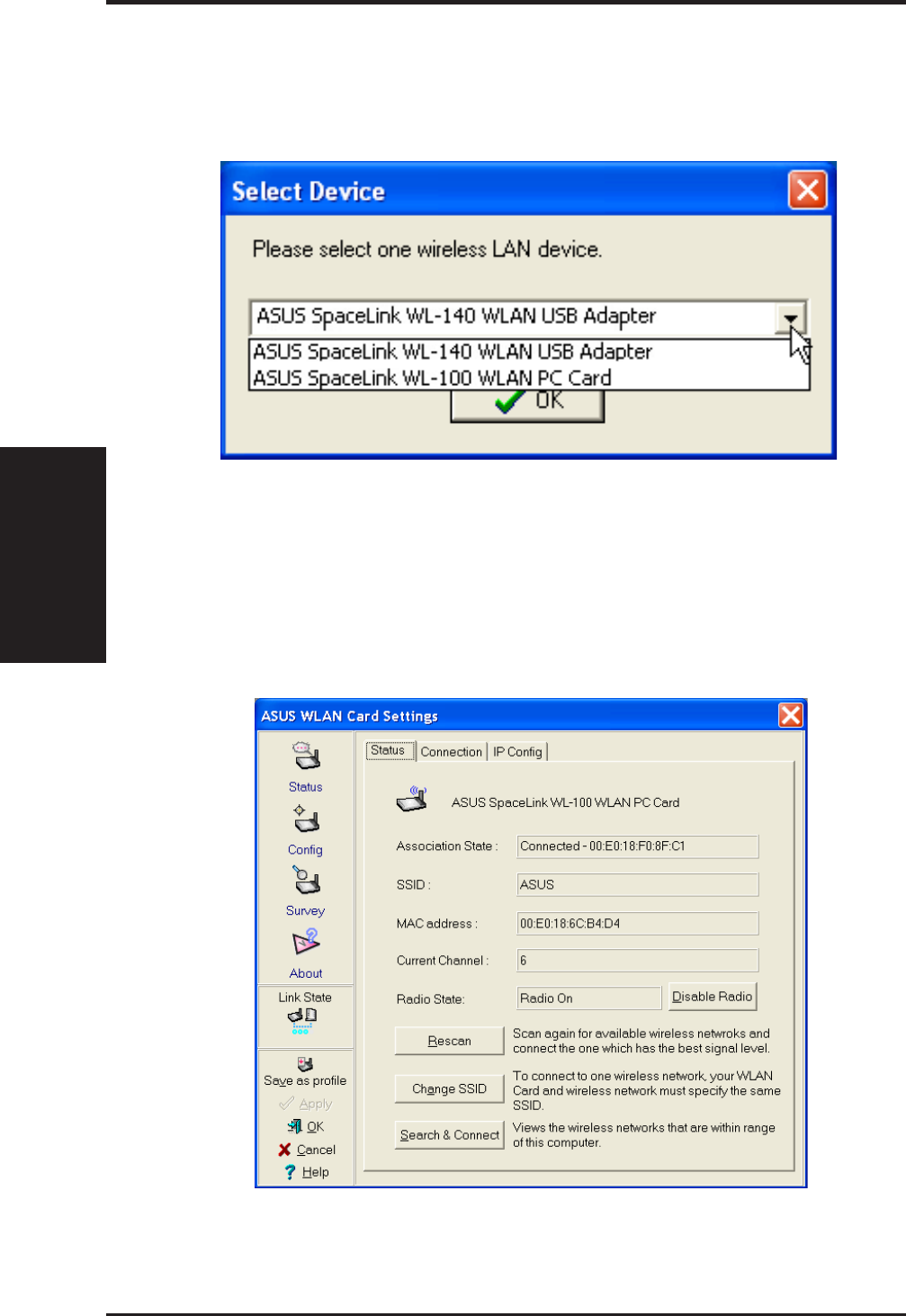
11 ASUS WLAN mini-PCI card
Reference
Chapter 3
4.1 Status - Status Tab
You can view the information about the ASUS WLAN mini-PCI card from
the general menu. These fields are blank if the ASUS WLAN mini-PCI
card does not exist.
More than one ASUS WLAN Card
If you have more than one ASUS WLAN Card. You will be given a
device selection window when you launch the “Wireless Settings” utility.

ASUS WLAN mini-PCI card 12
Reference
Chapter 3
Association State
Shows the ASUS WLAN mini-PCI card association status as follows:
Connected – The station is now associated with one wireless LAN
device. Also, indicates the MAC address of this device.
Scanning... – The station is now attempting to authenticate and associ-
ate with the desired Access Point.
Disconnected – If the link is connected and no beacon received, then
the set adapter is no longer connected.
INT_TEST_FAIL – Interrupt test failed.
NOT_AVAILABLE – Cannot get PC Card status.
SSID
Shows the SSID that the ASUS WLAN mini-PCI card is currently using.
MAC address
Indicates the hardware address of the ASUS WLAN mini-PCI card. MAC
address is a unique identifier for networking devices (typically written as
twelve hexadecimal digits 0 through 9 and A through F, six hexadecimal
numbers separated by colons, i.e. 00:01:24:F0:05:C0). This parameter is
read-only and unique.
Current Channel
Shows the radio channel that the ASUS WLAN mini-PCI card is currently
using.
Radio State
Shows whether the wireless radio is ON or OFF.
When the wireless radio is turned OFF, the following icon ap-
pears in the upper left of the “Settings” property page.
When the wireless radio is turned ON, the following icon ap-
pears in the upper left of the “Settings” property page.

13 ASUS WLAN mini-PCI card
Reference
Chapter 3
Button
Enable Radio/Disable Radio – You can click the Disable Radio button to
turn OFF the wireless radio. When you click this button, the Radio State
field indicates that the radio has been turned OFF and the remaining fields
in this window display either a “0” or “Not Applicable”. Click this button
again to turn the radio back ON.
Rescan – Force the radio to rescan all available channels. If your link qual-
ity or signal strength is poor, rescanning can be used to push the radio OFF
a weak Access Point and search for a better link with another Access Point.
This function will take some time.
Change SSID – Click on this to set the SSID.
Search & Connect – Click on this to connect to an available network.
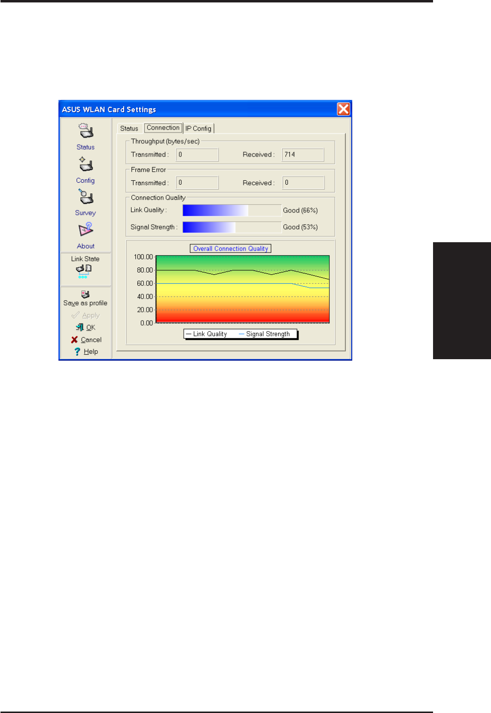
ASUS WLAN mini-PCI card 14
Reference
Chapter 3
4.2 Status - Connection Tab
You can view the current link statistics about the ASUS WLAN mini-PCI
card. These statistics are updated once per second and are valid only if the
ASUS WLAN mini-PCI card exists.
Throughput
Transmitted – The number of bytes in frames that were transmitted.
Received – The number of bytes in frames that were received.
Frame Error
Transmitted – The number of frames that were not successfully transmitted.
Received – The number of frames that were not successfully received.
Connection Quality
Link Quality – Reflects the quality level related to the Access Point the
station is currently connected to. Ratings are: Excellent, Good, Fair, and Poor.
Signal Strength – Reflects the signal level related to the Access Point the
station is currently connected to. Ratings are: Excellent, Good, Fair, and Poor.
Overall Connection Quality
Derives from the current “Link Quality” and the current “Signal Strength”.
A graph displays a connection quality range between 0 and 100 percent.
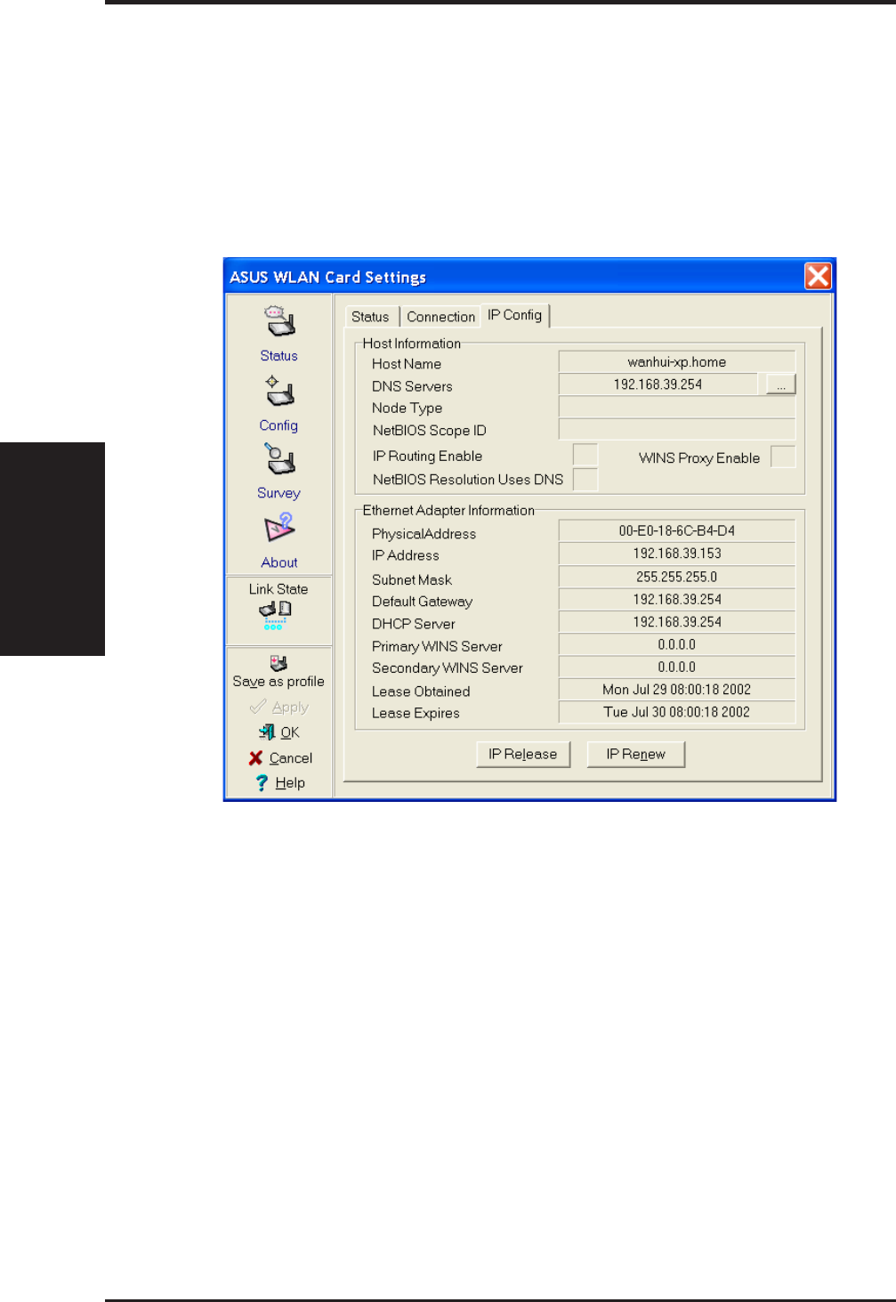
15 ASUS WLAN mini-PCI card
Reference
Chapter 3
4.3 Status - IP Config Tab
IP Config tab shows all the current network configuration information for
the ASUS WLAN mini-PCI card. Use it to verify your network settings.
IP CONFIG will display all the current TCP/IP configuration values in-
cluding the IP address, subnet mask, default gateway and Windows Inter-
net Naming Service (WINS) and DNS configuration.
Button
IP Release - Releases the DHCP IP address for the ASUS WLAN mini-PCI
card.
IP Renew - Renews the DHCP IP address for the ASUS WLAN mini-PCI
card.
NOTE : The IP Release and IP Renew buttons can only be used on the
ASUS WLAN mini-PCI card that is configured with DHCP.
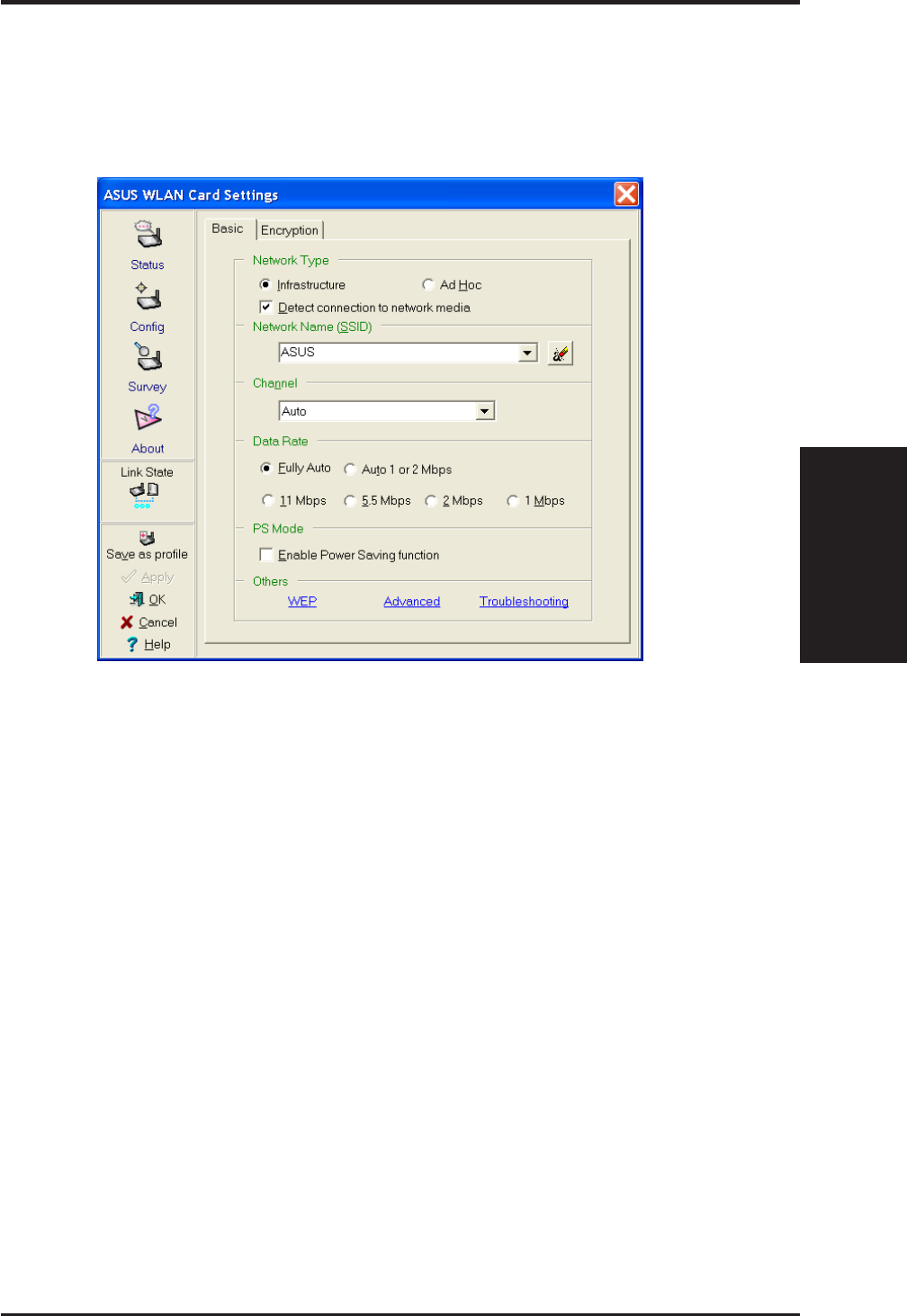
ASUS WLAN mini-PCI card 16
Reference
Chapter 3
4.4 Config - Basic Tab
Lets you can change the ASUS WLAN mini-PCI card configurations with-
out rebooting your computer.
Network Type
Infrastructure – Select the Infrastructure mode to establish a connec-
tion with an Access Point. Your computer is able to access wireless
LAN and wired LAN (Ethernet), via an associated access point. The
Channel field turns to “Auto” when “Infrastructure” is selected.
Ad Hoc – Select the “Ad Hoc” mode to communicate directly with
each other without using an Access Point. An “Ad Hoc” network is
typically formed quickly and easily without pre-planning. For example,
share meeting notes between networked computers in a meeting room.

17 ASUS WLAN mini-PCI card
Reference
Chapter 3
SSID
Use the SSID filed to configure the SSID for the ASUS WLAN mini-PCI
card. You can enter a new SSID or select one from the drop-down list box.
SSID stands for “Service Set Identifier”, which is a string used to identify a
wireless LAN. You will only be able to connect Access Points which has the
same SSID as the one you set. Use different SSIDs to segment the wireless
LAN and increase security. SSIDs must all be printable characters and hav-
ing a maximum of 32 case sensitive characters, such as “ Wireless LAN”.
Set the SSID to “any” if you wish to allow your station to connect to
any IEEE 802.11 Infrastructure Network it can find. When you set to
“any”, “Scanning...” will begin and may take a long time. Use “Sur-
vey” to view all Access Points within range and their SSIDs.
Channel
Using the Channel field to select the radio channel for ASUS WLAN mini-PCI
card. In an “infrastructure” network, your PC Card will automatically se-
lect the correct frequency channel required to communicate with an Access
Point, this parameter will be fixed in “Auto” and cannot be changed. In an
“Ad Hoc” network, you can decide the channel number for the ASUS WLAN
mini-PCI card. Any ASUS WLAN mini-PCI card can communicate in
the same network if each has the same frequency channel setting. The radio
channels you may use depend on the regulations in your country. For United
States (FCC) and Canada (IC), channels 1 to 11 are supported. For Europe
(ETSI) except Spain and France, channels 1 to 13 are supported. For Spain
channel 10 and 11 are supported. For France, channels 10 to 13 are sup-
ported. For operation in Japan (MKK), channels 1 to 14 are supported.
Data Rate
Fully Auto – Automatic transmit data rate falls back to 1, 2, 5.5, or 11
megabits per second when necessary to maintain transfers with devices.
Auto 1 or 2 Mbps – The PC Card will adjust to the most suitable trans-
mission rate. The transmit data rate is either 1 Mbps or 2 Mbps.
11 Mbps – Fix data rate to 11 megabits per second.
5.5 Mbps – Fix data rate to 5.5 megabits per second.
2 Mbps – Fix data rate to 2 megabits per second.
1 Mbps – Fix data rate to 1 megabits per second.

ASUS WLAN mini-PCI card 18
Reference
Chapter 3
Other
WEP - Click on this to show the "Encryption" page.
Advanced - Click on this to show the "Advanced" tab. In most cases, the
default values do not have to be changed.
Troubleshooting. - Click on this to show the "Troubleshooting" utility.
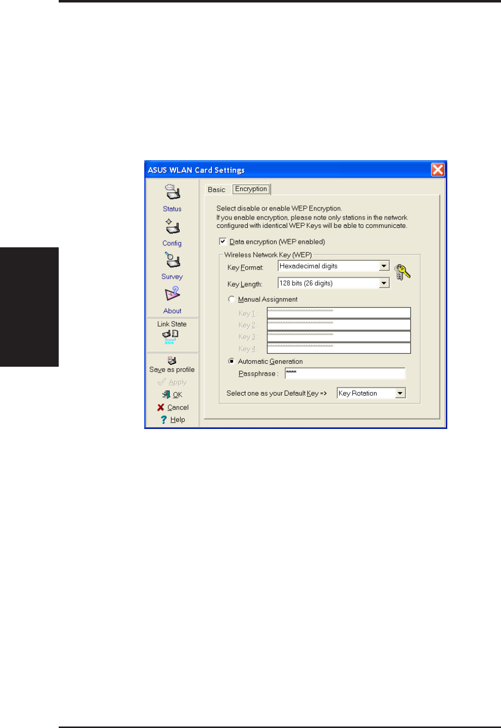
19 ASUS WLAN mini-PCI card
Reference
Chapter 3
4.5 Config - Encryption Tab
Lets you configure the ASUS WLAN mini-PCI card encryption settings.
For data confidentiality in a wireless environment, IEEE 802.11 specifies a
Wired Equivalent Privacy (WEP) algorithm to offer transmission privacy
similar to wired network. The WEP uses keys to encrypt transmitted data
packets and decrypt received data packets. The encryption process can
scramble frame bits to avoid disclosure to others.
Data encryption (WEP enabled)
This option allows you to enable or disable the Wired Equivalent Privacy
(WEP) function. If this check box is selected, a WEP Key is used to en-
crypt your data before it is transmitted over the air.
If you enable WEP encryption, you will only be able to communicate with
wireless devices that use the same WEP keys.
WEP Key
This option is enable only if you enable WEP Encryption. The WEP Key is
a 64 bits (5 byte) or 128 bits (13 byte) Hexadecimal digits that is used to
encrypt transmit data packets and decrypt received data packets.

ASUS WLAN mini-PCI card 20
Reference
Chapter 3
Key Format
You can enter the WEP Key as Hexadecimal digits (0~9, a~f, and A~F), or
as ASCII characters, based on the state of the Key Format.
Key Length
For 64 bits encryption, each Key contains exactly 10 hex digits, or 5 ASCII
characters. For 128 bits encryption, each Key contains exactly 26 hex dig-
its, or 13 ASCII characters.
Two ways to assign WEP keys
Manual Assignment – When you click this button, the cursor appears in
the field for Key 1. For 64-bit encryption, you are required to enter four
WEP Keys. Each Key contains exactly 10 hex digits (0~9, a~f, and A~F).
For 128-bit encryption, you are required to enter four WEP Keys. Each
Key contains exactly 26 hex digits (0~9, a~f, and A~F).
Automatic Generation – Type a combination of up to 64 letters, numbers,
or symbols in the Passphrase column, then the Wireless Settings Utility
uses an algorithm to generate four WEP Keys for encryption.
NOTE: This function eases users from having to remember their
passwords and is compatible to some existing WLAN utilities, but
this is not very secure. “Manual Assignment” is more secure.
Default Key – The Default Key field lets you specify which of the four
encryption keys you wish to use to transmit data on your wireless LAN.
You can change the default key by clicking on the down arrow at the right
of this field, selecting the number of the key you want to use, and then
clicking the Apply button. As long as the Access Point or station with which
you are communicating has the same key in the same position, you can use
any of the keys as the default.
Click the Apply button to create your encryption keys. After you click the
Apply button, the “Wireless Settings” utility uses asterisks to mask your
keys.
Click Apply to save and activate the new configurations.

21 ASUS WLAN mini-PCI card
Reference
Chapter 3
64/128bits versus 40/104bits
You may be confused about configuring WEP encryption, especially when
using multiple wireless LAN products from different vendors. There are
two levels of WEP Encryption: 64 bits and 128 bits.
First, 64 bit WEP and 40 bit WEP are the same encryption method and can
interoperate in the wireless network. This lower level of WEP encryption
uses a 40 bit (10 Hex character) as a “secret key” (set by user), and a 24 bit
“Initialization Vector” (not under user control). This together makes 64
bits (40 + 24). Some vendors refer to this level of WEP as 40 bits and
others refer to this as 64 bits. ASUS WLAN card products use the term
64 bits when referring to this lower level of encryption.
Second, 104 bit WEP and 128 bit WEP are the same encryption method
and can interoperate in the wireless network. This higher level of WEP
encryption uses a 104 bit (26 Hex character) as a “secret key” (set by user),
and a 24 bit “Initialization Vector” (not under user control). This together
makes 128 bits (104 + 24). Some vendors refer to this level of WEP as 104
bits and others refer to this as 128 bits. ASUS WLAN card products use
the term 128 bits when referring to this higher level of encryption.

ASUS WLAN mini-PCI card 22
Reference
Chapter 3
NOTE: This page is for advanced users. Do not change these set-
tings if you do not fully understand these items.
RTS Threshold
Defines the size of packets that the station uses for RTS/CTS handshake
boundary. Setting the minimum size packet too small causes RTS packets
to be sent more often, adding excessive overhead to the network and de-
creasing network utilization. However, the more often RTS packets are
sent, the more transmission collisions can be avoided. RTS threshold ranges
from 0 to 2346 in 64 steps.
Fragmentation Threshold
Define the number of bytes used for fragmentation boundary. If the length
of the data unit exceedsthis parameter , it will be divided into smaller frag-
ments for transmission. Each of the fragments is sent independently. If
there is a significant interference present, set the fragment size smaller.
Otherwise,set the fragment size lar ger. Because send multiple frames lead
to overhead on the network.Fragmentation Threshold ranged from 256 to
2432 steps 128.
4.6 Config - Advanced Tab
Advanced tab provides some additional settings for the ASUS WLAN
mini-PCI card. The “Advanced” tab is hidden until you click Advanced on
the Config - Basic page.

23ASUS WLAN mini-PCI card
Reference
Chapter 3
Authentication Algorithm
Because there is no precise bound in wireless LANs, it needs to be imple-
mented in another mechanism to provide a higher level of security. That is
where Authentication services come in. If a mutual authentication relation-
ship has not been established between the ASUS WLAN mini-PCI card(s)
and the Access Point(s), an association cannot be established.
Auto based on WEP setting – Switch the authentication mode based upon
the ASUS WLAN mini-PCI card Client using WEP encryption or not.
Open System – A null authentication algorithm. A station can authenticate
with any other station or Access Point and without checking any WEP Key,
even if one exists.
Share Key – In a Share Key Authentication system, four-step exchange of
frames is required to validate that the station is using the same WEP Key as
the Access Point. Using this Authentication mechanism requires imple-
mentation of the WEP option.
Maximum Listen Interval
This value is used to indicate how often a station will wake up to listen to
beacon management frames. Listen intervals range from 0 to 77 in steps of 1.
Preamble Mode
This parameter is used to control whether frames will transmit with the
long or short preamble.
Click Apply to save and activate the new configurations.
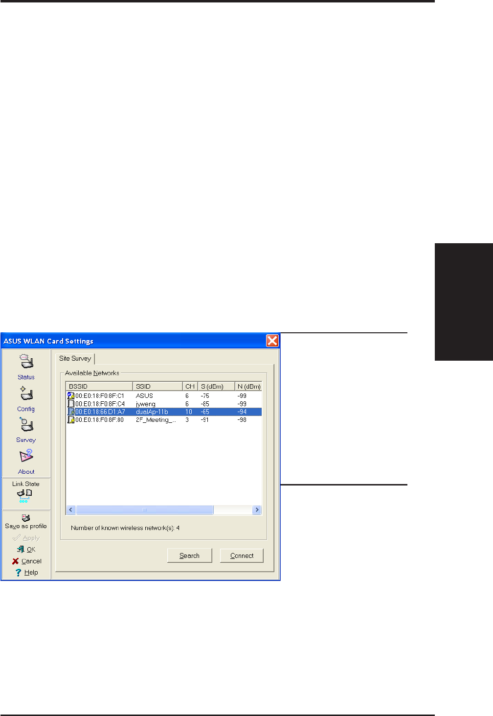
ASUS WLAN mini-PCI card 24
Reference
Chapter 3
4.7 Survey - Site Survey Tab
Use the Site Survey tab to view statistics on the wireless networks avail-
able to the ASUS WLAN mini-PCI card. The Site Survey tab is read-only
with no user configurable data fields. Use the Site Survey tab to view the
following network parameters.
•BSSID – View the IEEE MAC addresses of the available networks.
•SSID – View the SSID (service set identification) within available networks.
•CH – View the direct-sequence channel used by each network.
•S (dBm) – Signal field to view the strength of the signal transmitted by
each network. This information is helpful in determining which network
you should be associated to. The value is then normalized to a dBm value.
•N (dBm) – Noise field to view average noise level statistics and Rela-
tive Signal Strength Information (RSSI). This information is helpful in
determining which network you should be associated to. The value is
then normalized to a dBm value.
•Type – View wireless network status information, the value is either
AP (infrastructure) or STA (Ad Hoc).
•WEP – View wireless network WEP encryption information, the value
is either OFF (disable encryption) or ON (enable encryption).
Buttons
Search – Scan all available wireless networks and show the scan result in
the “Available Network List”.
Connect – To associate a network, select it from the “Available Network
List” and click this button.
Some Access
Points can disable
broadcasting SSID
to hide themselves
from “Site Survey”
or “Site Monitor”
for added security
but still allow you to
join if you know
their SSID.
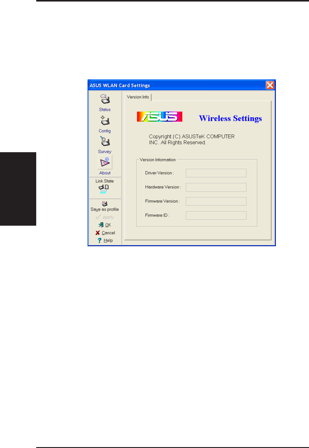
25 ASUS WLAN mini-PCI card
Reference
Chapter 3
4.8 About - Version Info Tab
Click about to view version information. The version under the copyright
is the utility version. The version information field includes driver, hard-
ware, and firmware versions.

ASUS WLAN mini-PCI card 26
Reference
Chapter 3
To Exit Wireless Settings
To exit Wireless Settings, you can click OK or Cancel. This utility may be
closed at any time and from any tab. If you did not save the configuration
settings, you will be prompted to do so.
4.9 Link Status
ASUS WLAN mini-PCI card connection quality icon appears on the left
of the ASUS WLAN Card Settings. Use the icon to view the current signal
quality of the adapter.
Excellent Link Quality (Infrastructure)
Good Link Quality (Infrastructure)
Fair Link Quality (Infrastructure)
Poor Link Quality (Infrastructure)
Not linked (Infrastructure)
Linked (Ad Hoc)
Not Linked (Ad Hoc)

27ASUS WLAN mini-PCI card
Reference
Chapter 3
5. Mobile Manager
Mobile Manager is a convenient tool to setup and manage network loca-
tion settings. Mobile Manager lets users configure multiple alternative con-
figurations for different locations. You only need to set this once, and then
easily switch configurations when you change your location.
Starting Mobile Manager
• Click the Windows Start button, select Programs, select ASUS Util-
ity, select WLAN Card, and then click Mobile Manager.
or
• Right-click the Control Center icon on the Windows taskbar and then
click Mobile Manager.
Using Mobile Manager - Quick Guide
1. The first time you launch the Mobile Manager utility, it will automati-
cally generate configurations that stores the current settings of all in-
stalled network devices in your system.
2. Change the name of the configuration to a descriptive name like “Work-
Meeting Room” or “Home-ADSL”.
3. On the File menu, click New Configuration, the New Configuration
Wizard dialog appears. Follow the on-screen instructions to create your
own location configurations.
4. After you have created your configurations, you can see them in the
main window.
5. Select the configuration you want to use and then click Mobilize Con-
figuration from the Mobilize pull-down menu. Your system will then
switch to the network settings configured to your chosen selection.
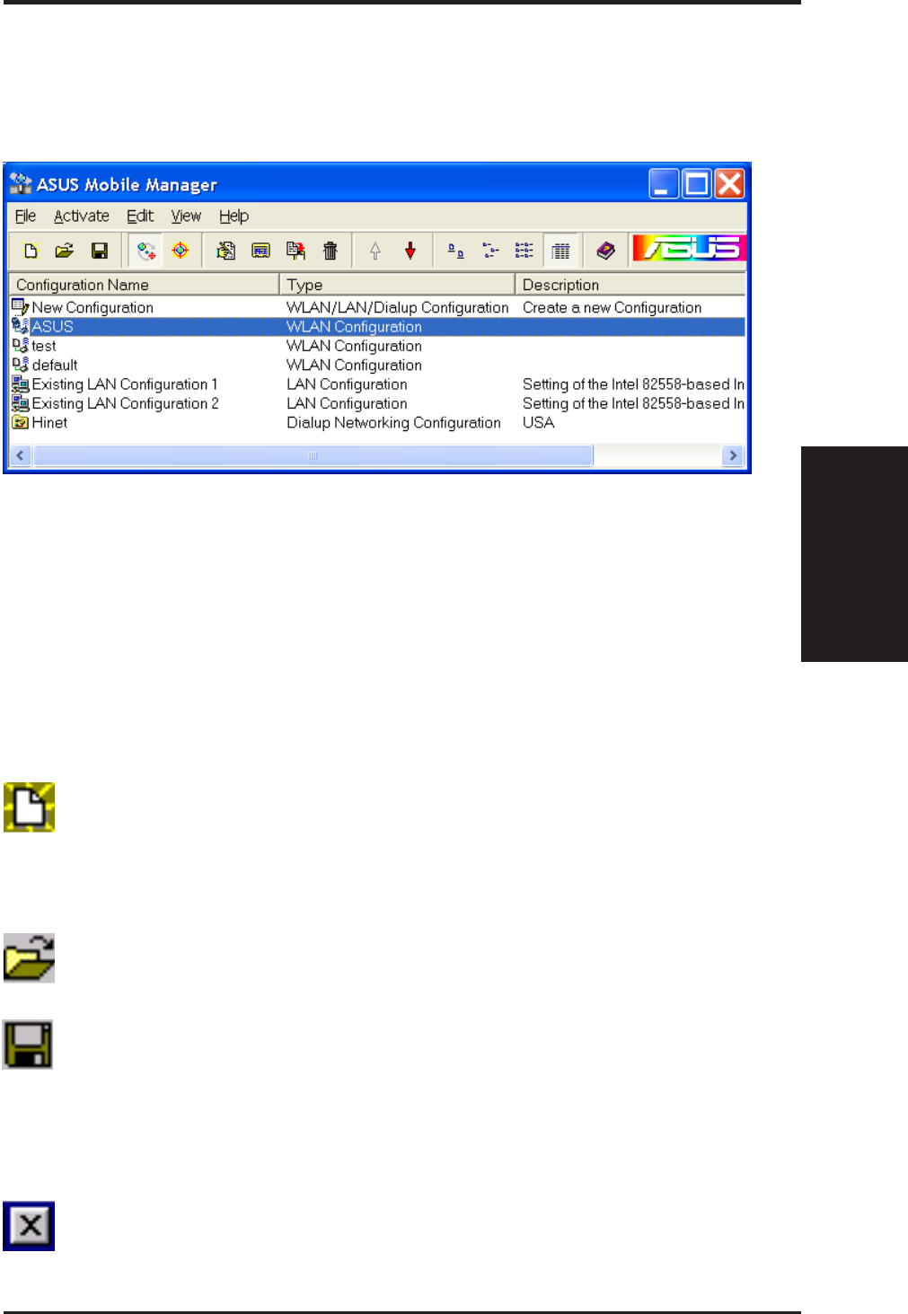
ASUS WLAN mini-PCI card 28
Reference
Chapter 3
5.1 Main Window
You can use the Mobile Manager utility main window to create a new configura-
tion, edit a configuration or activate a configuration. The main window includes
a menu bar, tool bar, and a list view for showing existing configurations.
Using the pull-down menu and toolbar
The following topics show the commands available from the Mobile Manager
pull-down menu and toolbar. If no configuration is selected, some commands
will be grayed out and inaccessible. The toolbar contains buttons for many of
the most commonly used commands in Mobile Manager. It allows quick ac-
cess to some of the most useful features of Mobile Manager. The commands
provided by the toolbar buttons are also available from the pull-down menu.
File Menu
New Configuration - Select New Configuration in the File menu
to open a New Configuration Wizard dialog. Use the New Configu-
ration Wizard dialog to create a new configuration. See Using New
Configuration Wizard for details on this command.
Import Configuration - Load a configuration from an INI File.
Export Configuration - Save the selected configuration (contain-
ing Wireless Settings, TCP/IP Settings, Network Settings, ...) to an
INI File. The INI file can be placed on a floppy diskette and then
imported by other computers using Mobile Manager. This can also
be used as a backup feature for yourself.
Exit - Close the Mobile Manager utility.
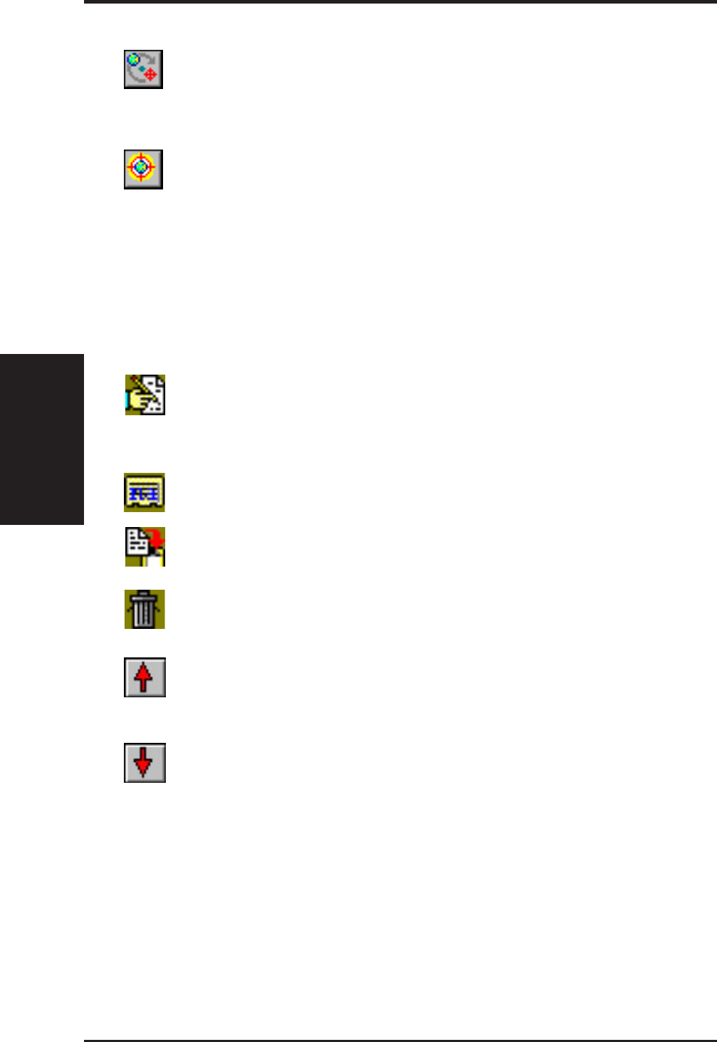
29 ASUS WLAN mini-PCI card
Reference
Chapter 3
Mobilize Menu
Auto Roaming – If an association changes, it will automatically
switch into a network configuration that you have made. If no asso-
ciations have been made, it will automatically connect to a wireless
network based on configurations that you specify.
Activate Configuration – Applies the configuration that you have
selected from the list. You may be prompted to restart Windows
depending on the required changes. Follow the instructions on the
screen. Windows 2000 and XP usually do not require restarting your
computer, but Windows 98 and ME usually will require a restart.
Edit Menu
All these commands are also available from the context menu that appears
when you right-click with a configuration in the Mobile Manager window.
Edit Configuration - Select Edit Configuration in the Edit menu to
open an Edit Configuration dialog to edit selected configuration
items. See “Using Edit Configuration” for details on this command.
Rename - Change the name of the selected configuration.
Copy - Duplicate the selected configuration.
Delete - Discard the selected configuration.
Up - Raises the position of the selected wireless netowork configu-
ration in the preferred network list.
Down - Lowers the position of the selected wireless netowork con-
figuration in the preferred network list.

ASUS WLAN mini-PCI card 30
Reference
Chapter 3
Help Menu
Contents - Displays the WinHelp contents window (the one you
are reading now) for online Help.
About Mobile Manager - Displays the version number and copy-
right information for Mobile Manager. Click on the logo to connect
to ASUS’ website.
View Menu
Large Icons - Displays large icons for each configuration.
Small Icons - Displays small icons for each configuration.
List - Shows the configuration names in a list.
Details - The Detailed view expands this list to include information
about the configurations. The information includes configuration
name, type, and description.
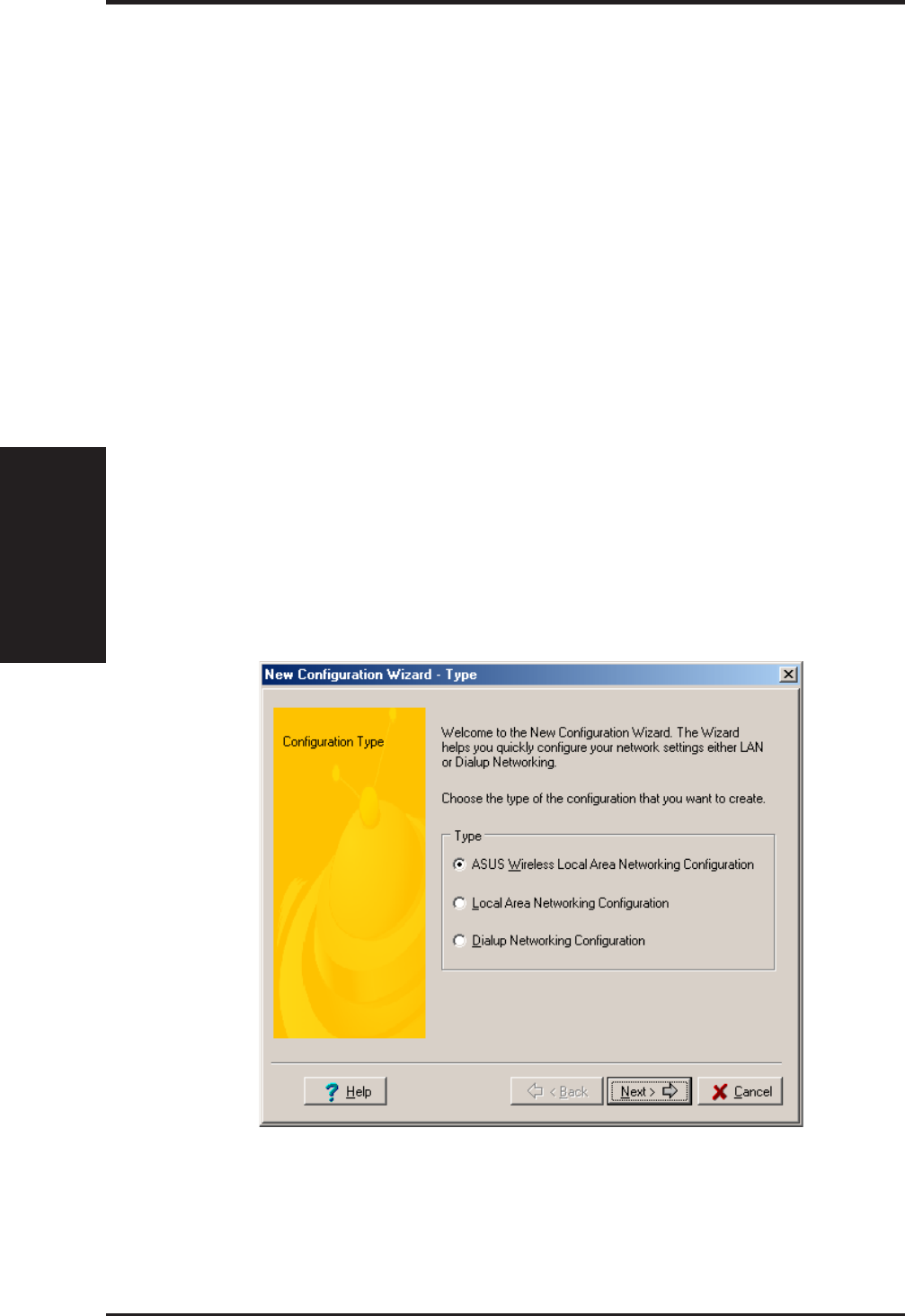
31 ASUS WLAN mini-PCI card
Reference
Chapter 3
5.2 Using New Configuration Wizard
Create a new configuration
Create a new configuration if you are in a specific location that does not
have an existing configuration defined. Use the New Configuration Wiz-
ard to create a configuration in a few easy steps.
1. Do one of the following:
• On the File menu, click New Configuration.
or
• Double-click New Configuration on the Main window.
Then the New Configuration Wizard dialog starts.
2. Choose the type of configuration that you want to create and click Next.
•Wireless Local Area Network Configuration: You must have an
ASUS WLAN mini-PCI card installed in your PC.
•Wired Local Area Network Configuration: You must have a NIC (LAN
card) (other than ASUS WLAN mini-PCI card) installed in your PC.
•Dialup Networking Configuration: You must have a modem in-
stalled in your PC.

ASUS WLAN mini-PCI card 32
Reference
Chapter 3
3. Enter the name and description you want to use for this configuration
in the Name and description field. And Click Next.
4. Follow the on-screen instructions, it will guide you through the process
of specifying the settings in your configuration. The Wizard reads the
current system settings (TCP/IP, NT Domain, Proxy, File, and Printer
Sharing) and displays it. Depending on the configuration that you have
created, you can set the following groups of settings:
• Wireless settings (for Wireless Configuration)
• Network settings (for Wireless/Wired Configuration)
• TCP/IP settings (for Wireless/Wired Configuration)
• Dialing settings (for Dialup Configuration)
• Dialup Networking settings (for Dialup Configuration)
• Internet settings (for Wireless/Wired/Dialup Configuration)
• Sharing settings (for Wireless/Wired/Dialup Configuration)
See “Using Edit Configuration” for detailed information on each.
5. Enter the appropriate information in the wizard. After specifying the
appropriate information on each page, click Next to continue.
6. On the final window of the New Configuration Wizard, you will see a
Finish button.
• If you do not want to use this new configuration now, click Finish
to save the new configuration. It will be shown in the Mobile Man-
ager main window.
or
• If you want to use this new configuration now, click Mobilize.
5.3 Using Edit Configuration
Edit an existing configuration
Edit a configuration if you want to view or change dialup or LAN settings.
• On the Edit menu, click Edit Configuration.
or
• Double-click one existing configuration on the Main window.
Then the Edit Configuration dialog starts.
The Edit Configuration dialog contains various settings, which you select
by clicking the buttons at the left of the window. Each setting is described
below.

33 ASUS WLAN mini-PCI card
Reference
Chapter 3
General settings
Name – This field is mandatory, and used for indicating the location
from which you are dialing or connecting to the network. For example,
if this is used for a meeting room at work, you can use a name like
“Work-Meeting Room”. If it is used for home on your ADSL, you can
name like “Home-ADSL”.
Description – This field is optional, you can use it to provide more
details about this configuration.
Network settings
Network settings include: “Identification” and “Microsoft Networking”.
Identification
Computer name – Give your computer a unique name of up to 15
characters. Thecomputer name is the name that others on your net-
work will see your computer as. For complete compatibility, do not use
spaces or symbols. It’s generally the same as the DNS hostname, for
example, “JohnDoe”.
Workgroup – Type an existing workgroup name or create a new
workgroup by typing a new name that contains up to 15 characters. Use
it to identify your computer group that you belong to.
Computer Description – This information is displayed as a comment
next to the computer name when the computer is seen in “Details” view
(select from the Windows pull-down menu). Use it to describe your
computer, for example, your name, or location.
Microsoft Networking
Logon validation – Specify how Windows 9x clients connect to a Win-
dows NT Server Domain at this location.Check Log on to Windows NT
domain box if you are using a Windows NT Server in domain control-
ler mode. And then enter the Window NT server domain name in Win-
dow NT domain field.
Network logon options – Specify how Windows 9x clients try to logon.
Select Quick logon to wait until the shared network drives is actually
used to attempt the login. Select Logon and restore network connections
to logon to all shared network drives when the user logs into Windows.

ASUS WLAN mini-PCI card 34
Reference
Chapter 3
Wireless settings
Network Type
Infrastructure – Select the Infrastructure mode to establish a connec-
tion with an Access Point.
Ad Hoc – Select the Ad Hoc mode to communicate directly with each
other without using an Access Point.
SSID
Using the SSID filed to configure the SSID setting for the ASUS WLAN
mini-PCI card. SSID stands for Service Set Identifier, which is a string
used to identify a wireless LAN. You will only be able to connect with an
Access Point, which has the same SSID. Use different SSIDs to segment
the wireless LAN and add security.
Note that the SSID must be all printable character string (case sensitivity)
and up to 32 characters long, such as “ WIRELESS LAN”. Set the SSID to
“any” if you wish to allow your station to connect to any IEEE 802.11
Infrastructure Network it can find.
Channel
Using the Channel filed to select the radio channel for PC Card. In infra-
structure network, your PC Card will automatically select the correct fre-
quency channel required to communicate with an Access Point, this param-
eter will be fixed in “Auto” and can’t change it. In an Ad Hoc Network, you
can decide channel number for the PC Card to operate. PC Cards can com-
municate in the network if each has the same frequency channel setting.
Data Rate
Fully Auto – Automatic transmit data rate fallback to 1, 2, 5.5, or 11
megabits per second for communication with other devices.
Auto 1 or 2 Mbps – The ASUS WLAN mini-PCI card will use the most
suitable transmission rate of either 1 Mbps or 2 Mbps.
11 Mbps – Fix transmit data rate to 11 megabits per second.
5.5 Mbps – Fix transmit data rate to 5.5 megabits per second.
2 Mbps – Fix transmit data rate to 2 megabits per second.
1 Mbps – Fix transmit data rate to 1 megabits per second.
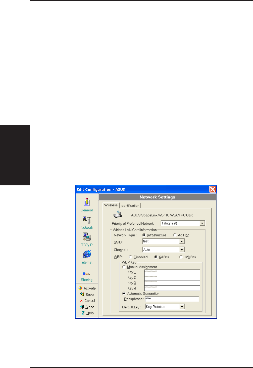
35ASUS WLAN mini-PCI card
Reference
Chapter 3
WEP
Select disable or enable (64-bit or 128-bit) WEP encryption. The WEP Key
is a 64-bit (5 byte) or 128-bit (13 byte) Hexadecimal digit that is used to
encrypt transmit data packets and decrypt received data packets.
TCP/IP settings
TCP/IP settings include five tabs: Device, IP Address, Gateway, DNS, and
WINS.
Device
Choose the network adapter that you want to use for this configuration.
IP Address
Obtain an IP address from a DHCP server – Dynamic host configu-
ration protocol (DHCP) server assigns IP addresses automatically within
a specified range to devices.
Specify an IP address – Ask your network administrator for the IP
address and subnet mask that you should use. Type in the IP Address
and Subnet Mask fields manually.

ASUS WLAN mini-PCI card 36
Reference
Chapter 3
Gateway
Specify the gateways. There can be more than one specified.Set up the
primary gateway first.
Add a gateway - Type the IP address of the gateway in the New Gate-
way field and then click Add. The gateway you specified appears in the
Installed Gateways list. Repeat to specify another gateways. The value
in each field must be a number between 0 and 255. You can have up to
eight IP addresses for gateways.
Remove a gateway - Select the gateway from the Installed Gateways
list and click Remove.
DNS
Select Enable or Disable DNS. If you enable DNS, fill the following pa-
rameters.
Host – Enter the name of your computer. That is used to identifier the
computer on the Internet. The hostname is generally the same as the
Microsoft networking computer name, for example, “S82000W”.
Domain – Enter the TCP/IP domain name for your network.The full
domain name consists of one or more names that are separated by dots,
for example, “asus.com”.
DNS Server Search Order – Specify the DNS Servers in the desired
order to search for DNS information.
Domain Suffix Search Order – Add any domain suffixes that may be
valid attached to the end of Internet domain name.
WINS
Specify the WINS server. There can be more than one specified.Set up the
primary WINS server first.
Disable WINS Resolution – Do not use WINS resolution.
Enable WINS Resolution – Use WINS resolution. Specify the IP ad-
dresses of the WINS servers in the desired search order. Scope ID is
used when NetBIOS over TCP/IP is enabling on the workstations. If
this protocol has been enabled, then every workstation group must have
the same Scope ID for those computers to communicate within the group.
The Scope ID is usually left blank.
Use DHCP for WINS Resolution – If a DHCP server is available that
is configured to provide information on available WINS servers.

37 ASUS WLAN mini-PCI card
Reference
Chapter 3
Dialing settings
Specify how the call will be dialed. This is useful if you want to change the
call to a calling card, use your computer from different locations, or add a
dial prefix, country code, or area code automatically.
Dialup Networking settings
Dialup Networking settings include four tabs: Device, Phone Number,
Server Type, and TCP/IP.
Device
Choose the modem you want to use by Dial-Up Networking to connect to
another computer for this connection.
Phone Number
Specify area code, telephone number, and country code for this connec-
tion. Clear the Use area code and Dialing Properties checkbox, if you
want to ignore area code and dialing settings.
Server Type
Type of Dial-Up Server – Select the server type for this connection.
Advanced options
Select Log on to network checkbox to specify that Dial-Up Networking
will attempt to log on to the network you are connecting to, using the user
name and password you typed when you logged on to Windows.
Select Enable software compression checkbox to specify whether incom-
ing or outgoing information is compressed before it is sent. This is useful
to speed up the transfer of information. Compression occurs only if both
computers are using compatible compression.

ASUS WLAN mini-PCI card 38
Reference
Chapter 3
Select Require encrypted password checkbox to specify that only en-
crypted passwords can be sent to or accepted by your computer. This is
useful if you need additional security for this connection. When type your
password while dialing out, this setting will encrypt your password but the
target computer must support encrypted passwords for your password to
be understood.
Allowed network protocols – Specifies the network protocols that your
computer can use.
Select NetBEUI protocol to connect to Windows NT, Windows for
Workgroups, or LAN Manager servers.
Select IPX/SPX Compatible protocol to connect to Netware and Win-
dows NT servers and Windows 98 computers.
Select TCP/IP protocol to connect to Internet and wide-area networks.
TCP/IP
Server assigned IP address – Specifies whether Dialup Networking
accepts an IP address from a ppp server. If the ppp server does not offer
an IP address, the IP address specified for TCP/IP Dial-Up Adapter in
the Network dialog box is used.
Specify an IP address – Provides a space for you to type the preferred
IP address for this connection. Dial-Up Networking tries to use this
address first.
Server assigned name server addresses – Specifies whether Dial-Up
Networking accepts a DNS and WINS server addresses from a ppp
server. If the ppp server does not offer DNS and WINS addresses, DNS
and WINS server addresses specified for TCP/IP Dial-Up Adapter in
the Network dialog box are used.
Specify name server addresses – Provides a space for you to type one
or two DNS and WINS server addresses for this connection only. Dial-
Up Networking tries to use these addresses first.
Use IP header compression – Specifies whether Dial-Up Networking
uses IP header compression for this connection. IP header compression
optimizes data transfer between computers.
Use default gateway on remote network – Specifies whether IP traf-
fic is routed to the WAN connection by default.

39 ASUS WLAN mini-PCI card
Reference
Chapter 3
Internet settings
A proxy server acts as a security barrier between your internal network
(Intranet) and the Internet, keeping other people on the Internet from gain-
ing access to confidential information on your internal network or your
computer.
Disable Proxy Server – Do not use proxy server.
Enable Proxy Server – Use the Proxy server to gain access to the Internet.
Use the same proxy server for all protocols – Specifies whether you
want to use the same proxy server to gain access to the Internet using
all protocols.
Servers – Provides spaces for you to type the address and port number
of the proxy server you want to use to gain access to the Internet over
HTTP, Secure, FTP, Gopher, and Socks protocol.
Exceptions
Do not use proxy server for address beginning with – Provides a space
for you to type the Web addresses that do not need to be accessed through
the proxy server. If you want to connect to a computer on your Intranet,
make sure you type its address in this box. You can use wild cards to match
domain and host names or addresses, for example, “*.company.com”,
“192.72.111.*”.
Bypass proxy server for local addresses – Specifies whether you want to
use the proxy server for all local (Intranet) addresses. You might be able to
gain access to local addresses easier and faster if you do not use the proxy
server.
Sharing settings
I want to be able to give others access to my files – Turn file sharing ON
or OFF. File sharing enables people using other computers to read or modify
files you share on your computer.
I want to be able to allow others to print to my printer(s) – Turn printer
sharing ON or OFF. Printer sharing enables people using other computers
to printer their files on your printers.
Click Save button to save all the changes you have made without clos-
ing the Edit Configuration dialog box.
Click Cancel button to close the Edit Configuration dialog box without
saving any changes you have made.
Click Close button to close the Edit Configuration dialog box and save
any changes that you have made.
ASUS WLAN mini-PCI card 40
Reference
Chapter 3
6. Site Monitor
Site Monitor measures the signal-to-noise (SNR) values of all available
wireless networks. This tool is used for determining the best placement of
Access Points to provide the best coverage for a wireless network.
6.1 Starting Site Monitor
• Click the Windows Start button, select Programs, select ASUS Util-
ity, select WLAN Card, and then click Site Monitor.
or
• Right-click the Control Center icon on the Windows taskbar and then
click Site Monitor.
6.2 Main Screen
Measures the signal-to-noise (SNR) values of all available wireless net-
works.
Some Access Points can disable broadcasting SSID to hide them-
selves from “Site Survey” or “Site Monitor” for added security
but still allow you to join if you know their SSID.
41 ASUS WLAN mini-PCI card
Reference
Chapter 3
6.3 Monitor
Directed link state test with one wireless network, including:
• SNR: This indicates the quality of communications within the current
network. The communication quality is based on signal level and noise
level measurements. In principle, the higher the SNR, the better your
communications quality.
• Communication Quality: Specifies the Communication Quality of the
Basic Service Set to which the station is currently connected to.
• Signal Level: Specifies the Average Signal Level of the Basic Service
Set to which the station is currently connected to.
• Noise Level: Specifies the Average Noise Level of the Frequency Chan-
nel currently used for communications.
• Throughput: This sends a specified number of data packets to the re-
mote host and calculates the average megabytes per second.
During the test, the Start button toggles to Stop. You can click Start button
to begin the link test and click Stop button at any time to terminate the test.
ASUS WLAN mini-PCI card 42
Reference
Chapter 3
7. Live Update
Live Update is a utility that allows you to update your ASUS WLAN mini-PCI
card’s firmware and drivers. The use of this utility assumes that you are
properly connected to Internet through an Internet Service Provide (ISP).
1. Insert the ASUS WLAN mini-PCI card Support CD into your CD-
ROM drive to bring up the autorun menu. If the autorun menu does not
show, double-click the CD drive icon in My Computer or run Setup.exe
in the root directory of your CD-ROM drive. When the Main menu
appears, click Run Live Update.
2. Select an update method from the pull-down menu.
Update Firmware/Driver from the Internet: Lets you update the
ASUS WLAN mini-PCI card’s firmware or driver from the Internet. The
updating (running the flash utility or the installation program) will be
done automatically.
Update Firmware/Driver from the Disk: Lets you specify the update
firmware or driver file from a disk. The updating (running the flash
utility or the installation program) will be done automatically.
Download Firmware/Driver from the Internet: Lets you download
the firmware or driver to a disk on your computer for manual updating
later.
43 ASUS WLAN mini-PCI card
Reference
Chapter 3
3. Follow any on-screen instructions or prompts to complete setup. If you
already have the latest revision of your ASUS WLAN mini-PCI card’s
firmware files or driver files, Live Update reports that no update is
necessary. When Live Update starts the firmware upgrade, a warning
message will tell you that incorrect firmware upgrades may cause your
ASUS WLAN mini-PCI card to malfunction. You can cancel the up-
date process at this point. If you continue, a message will tell you that
the update process has started. Do not turn OFF your computer until the
upgrade has completed. The upgrade will take approximately 30 sec-
onds. A subsequent message states whether the update was successful.
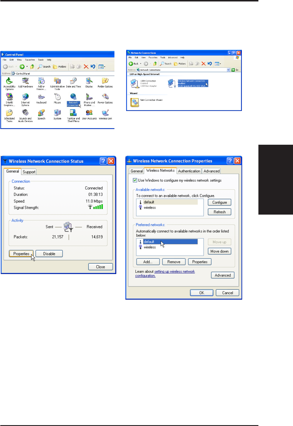
ASUS WLAN mini-PCI card 44
Reference
Chapter 3
8. Windows XP Wireless Properties
2. Double-click ASUS 802.11b Network...
1. Double-click System icon in the Control Panel.
3. The “General” page will show status,
duration, speed, and signal strength.
Signal strength is represented by green
bars with 5 bars meaning excellent signal
and 1 bar meaning poor signal.
4. The “Wireless Networks” page will show
Available networks and Preferred
networks. Use the Add button to add the
“SSID” of available networks and set the
connection preference order with the
Move up and Move down buttons. The
radio tower with a signal icon identifies
the currently connected access point.
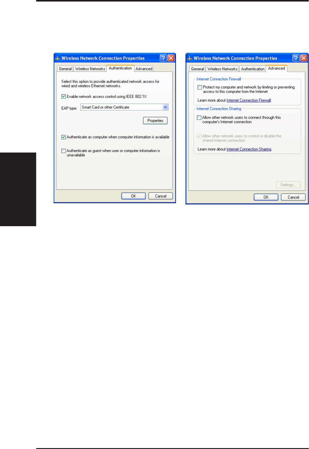
45 ASUS WLAN mini-PCI card
Reference
Chapter 3
5. The “Authentication” page allows you to
add security settings. Read Windows
help for more information.
6. The “Advanced” page allows you to set
firewall and sharing. Read Windows help
for more information.
8. Windows XP Wireless Properties (Cont.)

ASUS WLAN mini-PCI card 46
Troubleshooting
Chapter 4
Troubleshooting
The below troubleshooting guides provide answers to some of the more
common problems, which you may encounter while installing or using
ASUS WLAN mini-PCI card products. If you encounter difficulties that
are not mentioned in this section, please contact ASUS Wireless LAN Tech-
nical Support.
Verify if the mini-PCI Card is installed correctly.
When the ASUS WLAN mini-PCI card setup task is complete, you can
verify if the driver has been setup properly. Right click My Computer,
select Properties, and click the Device Manager tab. Then double-click
the Network adapters icon; you should see “ASUS 802.11b Network Ad-
apter” with an icon of expansion card. There should not be a “!” or “?” (prob-
lem) or “x” (disabled) symbol over this icon.
There is a yellow exclamation mark or a yellow question mark
in Device Manager in front of ASUS 802.11b Network Adapter.
To resolve the problem, you should update/reinstall the ASUS WLAN
mini-PCI card driver. In “Device Manager”, right click ASUS 802.11b
Network Adapter, select Properties, and select Driver tab. Click on Up-
date Driver button, then follow the “Update Device Driver Wizard” to
complete the driver installation.
In addition, you may be able to resolve this issue by reinstalling the driver.
Choose ASUS 802.11b Network Adapter, click Remove button in “De-
vice Manager”, and then run the Add New Hardware Wizard from the
Control Panel.
Cannot connect to any Access Points
Follow the procedure below to configure your ASUS WLAN mini-PCI card.
a. Verify that the “Network Type” is in “Infrastructure” mode.
b. Verify that the “SSID” of your ASUS 802.11b Network Adapter is set to
“any” or set to the same “SSID” of an Access Point.
c. Verify that the “Encryption” type is the same as that of an Access Point.
If you enabled “WEP” encryption, you must also set the same WEP
Keys on both sides.

47 ASUS WLAN mini-PCI card
Chapter 4 - Troubleshooting
Chapter 4
Cannot connect to a Station (ASUS WLAN mini-PCI card)
Follow the procedure below to configure your ASUS WLAN mini-PCI card
a. Verify that the “Network Type” is in “Ad Hoc” mode.
b. Verify that the “SSID” of your ASUS 802.11b Network Adapter is set
to “any” or set to the same “SSID” of the other station (or another ASUS
802.11b Network Adapter).
c. Verify that the “channel” of the ASUS 802.11b Network Adapter is “Auto”
or set to the same “channel” of the other station (or another ASUS 802.11b
Network Adapter).
d. Verify that the “Encryption” type is the same as the other station (or
another ASUS 802.11b Network Adapter). If “WEP” encryption is en-
abled, you must set the same “WEP” Keys on both stations.
Bad link quality or bad signal strength
There are two possible reasons. First is radio interference, keep the envi-
ronment around the ASUS WLAN mini-PCI card away from microwave
ovens and large metal objects. Second is the distance, decrease the distance
between your ASUS WLAN mini-PCI card and the Access Point or station
(or another ASUS WLAN mini-PCI card).
The TCP/IP protocol did not bind to the WLAN mini-PCI Card.
This will occur when the computer already has six TCP/IP bindings in
Windows 98 or ten bindings in Windows Me. These limits are imposed by
the Microsoft operating system.
Solution: If your computer already has the maximum number of TCP/IP
bindings, remove one of the network adapters from the Network configu-
ration before installing the ASUS WLAN mini-PCI card driver.
In Ad Hoc network mode, I have connected to a station but my
ASUS WLAN mini-PCI card cannot get an IP address.
Windows Me/2K/XP contains the “Media Sensing” feature, which can de-
tect a disconnect state on the media, it removes the bound protocols from
that adapter until it has detected a link. But in Ad Hoc mode, it will errone-
ously detect the media as being disconnected.
Solution: (1) Run Wireless Settings (2) click Config (3) uncheck Detect
connection to network media (4) click Apply (5) restart your computer

ASUS WLAN mini-PCI card 48
Glossary
Chapter 4
Glossary
Access Point (AP)
An networking device that seamlessly connects wired and wireless net-
works. Access Points combined with a distributed system support the cre-
ation of multiple radio cells that enable roaming throughout a facility.
Ad Hoc
A wireless network composed solely of stations within mutual communi-
cation range of each other (no Access Point).
Basic Service Area (BSS)
A set of stations controlled by a single coordination function.
Channel
An instance of medium use for the purpose of passing protocol data units
that may be used simultaneously, in the same volume of space, with other
instances of medium use (on other channels) by other instances of the same
physical layer, with an acceptably low frame error ratio due to mutual in-
terference.
Extended Service Set (ESS)
A set of one or more interconnected basic service set (BSSs) and integrated
local area networks (LANs) can be configured as an Extended Service Set.
Ethernet
The most widely used LAN access method, which is defined by the IEEE
802.3 standard. Ethernet is normally a shared media LAN meaning all de-
vices on the network segment share total bandwidth. Ethernet networks
operate at 10Mbps using CSMA/CD to run over 10-BaseT cables.
Gateway
A network component that acts as an entrance to another network.

49 ASUS WLAN mini-PCI card
Glossary
Chapter 5
IEEE 802.11
IEEE 802.xx is a set of specifications for LANs from the Institute of Elec-
trical and Electronic Engineers (IEEE). Most wired networks conform to
802.3, the specification for CSMA/CD based Ethernet networks or 802.5,
the specification for token ring networks. 802.11 defines the standard for
wireless LANs encompassing three incompatible (non-interoperable) tech-
nologies: Frequency Hopping Spread Spectrum (FHSS), Direct Sequence
Spread Spectrum (DSSS), and Infrared. 802.11 specifies a carrier sense
media access control and physical layer specifications for 1 and 2 Mbps
wireless LANs.
IEEE 802.11b
802.11b specifies a carrier sense media access control and physical layer
specifications for 5.5 and 11 Mbps wireless LANs.
Infrastructure
A wireless network centered about an access point. In this environment,
the access point not only provides communication with the wired network
but also mediates wireless network traffic in the immediate neighborhood.
IP (Internet Protocol)
The TCP/IP standard protocol that defines the IP datagram as the unit of
information passed across an Internet and provides the basis for
connectionless packet delivery service. IP includes the ICMP control and
error message protocol as an integral part. It provides the functional equiva-
lent of ISO OSI Network Services.
IP Address
An IP address is a 32-bit number that identifies each sender or receiver of
information that is sent across the Internet. An IP address has two parts: the
identifier of a particular network on the Internet and an identifier of the
particular device (which can be a server or a workstation) within that net-
work.
ISM Bands (Industrial, Scientific, and Medicine Bands)
Radio frequency bands that the Federal Communications Commission
(FCC) authorized for wireless LANs. The ISM bands are located at 902
MHz, 2.400 GHz, and 5.7 GHz.

ASUS WLAN mini-PCI card 50
Glossary
Chapter 4
ISP (Internet Service Provider)
An organization that provides access to the Internet. Small ISPs provide
service via modem and ISDN while the larger ones also offer private line
hookups (T1, fractional T1, etc.).
LAN (Local Area Network)
A communications network that serves users within a defined geographi-
cal area. The benefits include the sharing of Internet access, files and equip-
ment like printers and storage devices. Special network cabling (10 BaseT)
is often used to connect the PCs together.
NIC (Network Interface Card)
A network adapter inserted into a computer so that the computer can be
connected to a network. It is responsible for converting data from stored in
the computer to the form transmitted or received.
Packet
A basic message unit for communication across a network. A packet usu-
ally includes routing information, data, and sometimes error detection in-
formation.
PCMCIA (Personal Computer Memory Card International Association)
The Personal Computer Memory Card International Association (PCMCIA),
develops standards for PC cards, formerly known as PCMCIA cards. These
cards are available in three types, and are have about the same length and
width as credit cards. However, the different width of the cards ranges in
thickness from 3.3 mm (Type I) to 5.0 mm (Type II) to 10.5 mm (Type III).
These cards can be used for various functions, including memory storage,
landline modems and wireless modems.
Radio Frequency (RF) Terms: GHz, MHz, Hz
The international unit for measuring frequency is Hertz (Hz), equivalent to
the older unit of cycles per second. One megahertz (MHz) is one million
Hertz. One gigahertz (GHz) is one billion Hertz. The standard US electri-
cal power frequency is 60 Hz, the AM broadcast radio frequency band is
0.55-1.6 MHz, the FM broadcast radio frequency band is 88-108 MHz,
and wireless 802.11 LANs operate at 2.4 GHz.

51 ASUS WLAN mini-PCI card
Glossary
Chapter 5
SSID (Service Set ID)
SSID is a group name shared by every member of a wireless network. Only
client PCs with the same SSID are allowed to establish a connection.
Station
Any device containing IEEE 802.11 wireless medium access conformity.
TCP (Transmission Control Protocol)
The standard transport level protocol that provides the full duplex, stream
service on which many application protocols depend. TCP allows a pro-
cess or one machine to send a stream of data to a process on another. Soft-
ware implementing TCP usually resides in the operating system and uses
the IP to transmit information across the network.

ASUS WLAN mini-PCI card 52
Safety Statements
Federal Communications Commission Statement
This device complies with FCC Rules Part 15. Operation is subject to the follow-
ing two conditions:
• This device may not cause harmful interference, and
• This device must accept any interference received, including interference that
may cause undesired operation.
This equipment has been tested and found to comply with the limits for a class B
digital device, pursuant to Part 15 of the Federal Communications Commission (FCC)
rules. These limits are designed to provide reasonable protection against harmful
interference in a residential installation. This equipment generates, uses, and can
radiate radio frequency energy and, if not installed and used in accordance with the
instructions, may cause harmful interference to radio communications. However,
there is no guarantee that interference will not occur in a particular installation. If
this equipment does cause harmful interference to radio or television reception, which
can be determined by turning the equipment off and on, the user is encouraged to try
to correct the interference by one or more of the following measures:
• Reorient or relocate the receiving antenna.
• Increase the separation between the equipment and receiver.
• Connect the equipment into an outlet on a circuit different from that to which
the receiver is connected.
• Consult the dealer or an experienced radio/TV technician for help.
WARNING! The use of a shielded-type power cord is required in
order to meet FCC emission limits and to prevent interference to
the nearby radio and television reception. It is essential that only
the supplied power cord be used. Use only shielded cables to con-
nect I/O devices to this equipment. You are cautioned that changes
or modifications not expressly approved by the party responsible
for compliance could void your authority to operate the equipment.
Reprinted from the Code of Federal Regulations #47, part 15.193, 1993. Washing-
ton DC: Office of the Federal Register, National Archives and Records Adminis-
tration, U.S. Government Printing Office.
Canadian Department of Communications
This digital apparatus does not exceed the Class B limits for radio noise emissions
from digital apparatus set out in the Radio Interference Regulations of the Cana-
dian Department of Communications.
This Class B digital apparatus complies with Canadian ICES-003.
Cet appareil numérique de la classe B est conforme à la norme
NMB-003 du Canada.

53 ASUS WLAN mini-PCI card
7. Wireless LAN Safety Statements
MPE Safety Statement
Your device contains a low power transmitter. When device is transmitted it
sends out Radio Frequency (RF) signal.
FCC Radio Frequency Exposure Statement
This Wireless LAN radio device has been evaluated under FCC Bulletin
OET 65C and found compliant to the requirements as set forth in CFR 47
Sections 2.1091, 2.1093, and 15.247(b)(4) addressing RF Exposure from
radio frequency devices. The radiation output power of this Wireless LAN
device is far below the FCC radio frequency exposure limits. Nevertheless,
this device shall be used in such a manner that the potential for human con-
tact during normal operation – as a mobile or portable device but use in a
body-worn way is strictly prohibited.
CAUTION: To maintain compliance with FCC's RF exposure guide-
lines established in the ANSI C95.1 standards, this equipment should
be installed and operated with minimum distance 20cm between the
radiator and your body. Use on the supplied antenna. Unauthorized
antenna, modification, or attachments could damage the transmitter
and may violate FCC regulations.
Installation and use of this Wireless LAN device must be in strict accor-
dance with the instructions included in the user documentation provided
with the product. Any changes or modifications (including the antennas)
made to this device that are not expressly approved by the manufacturer
may void the user's authority to operate the equipment. The manufacturer is
not responsible for any radio or television interference caused by unautho-
rized modification of this device, or the substitution of the connecting cables
and equipment other than manufacturer specified. It is the responsibility of
the user to correct any interference caused by such unauthorized modifica-
tion, substitution or attachment. Manufacturer and its authorized resellers
or distributors will assume no liability for any damage or violation of gov-
ernment regulations arising from failing to comply with these guidelines.
Co-location Prohibition
This device must not be co-located or co-operated in conjunction with an-
other antenna or transmitter from another device.