Netgear orporated CG814WG WIRELESS CABLE MODEM User Manual CG814W
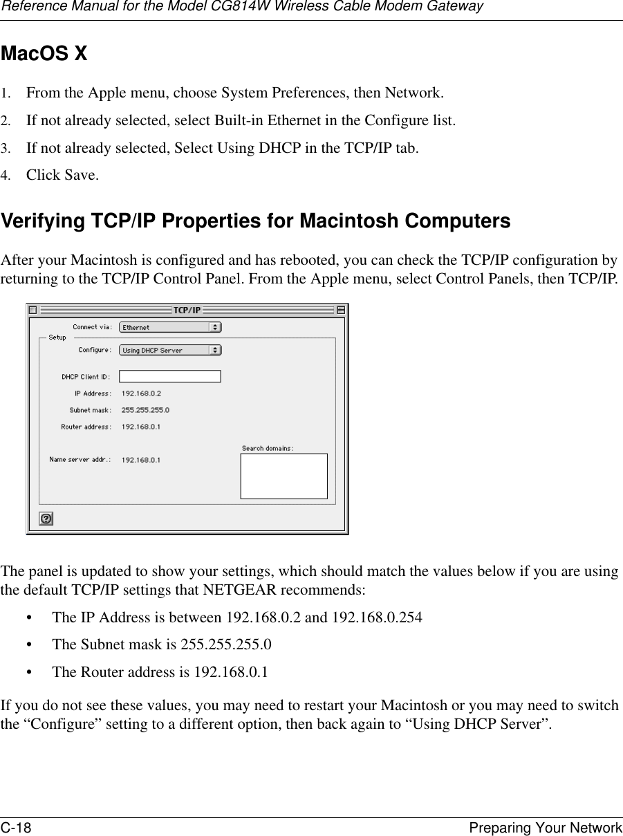
Netgear Incorporated WIRELESS CABLE MODEM CG814W
UserManual.wiki
>
Netgear orporated
>
CG814WG User Manual
USERS MANUAL
Navigation menu
Upload a User Manual
Namespaces
Wiki Guide
HTML
PDF
Info
Views
User Manual
Discussion / Help
Navigation

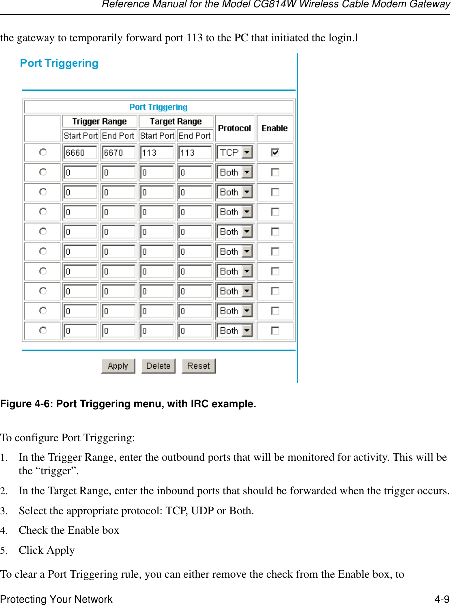
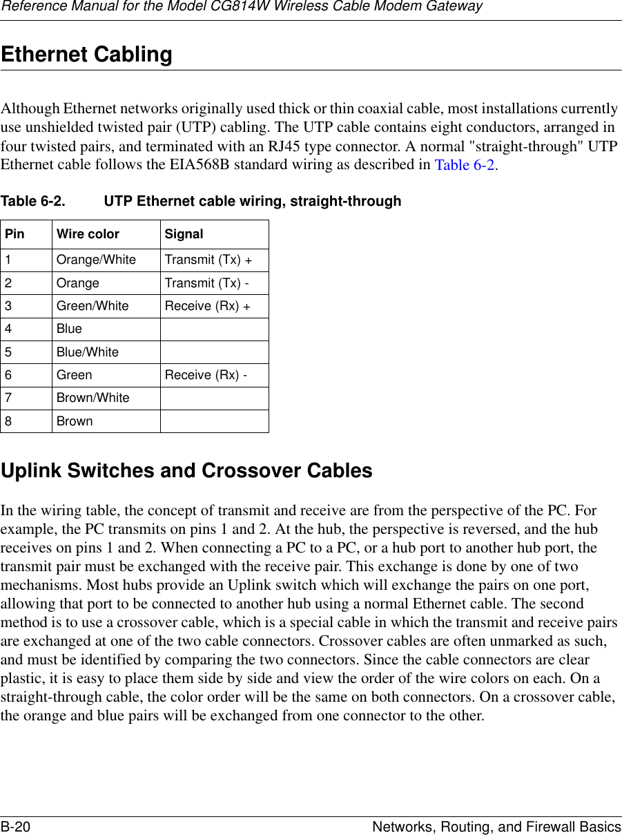
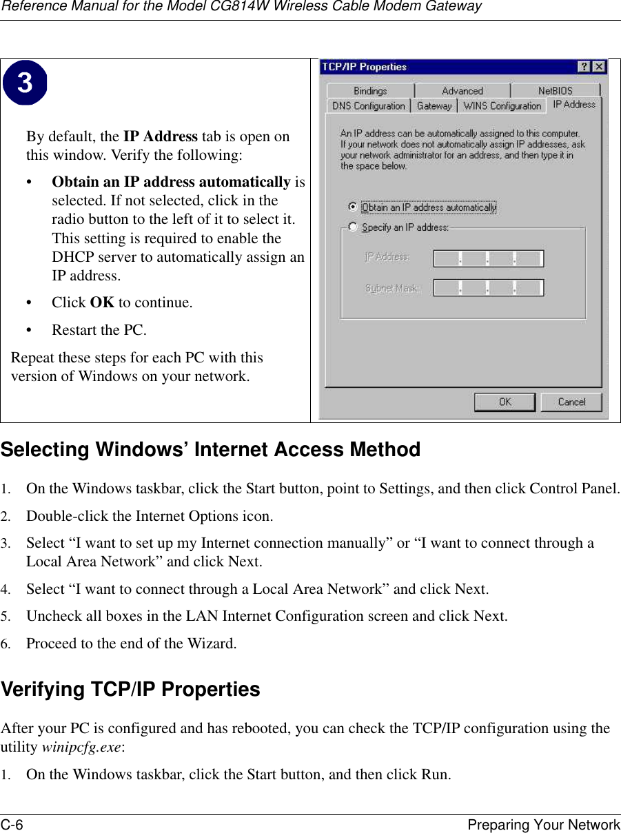
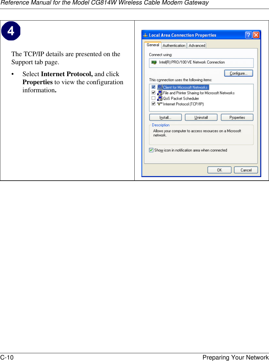
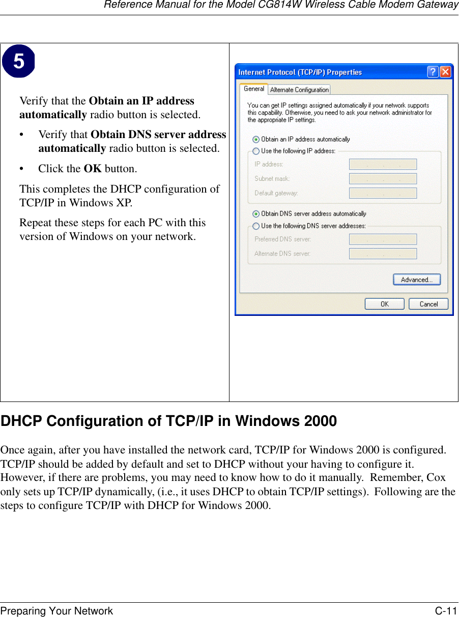
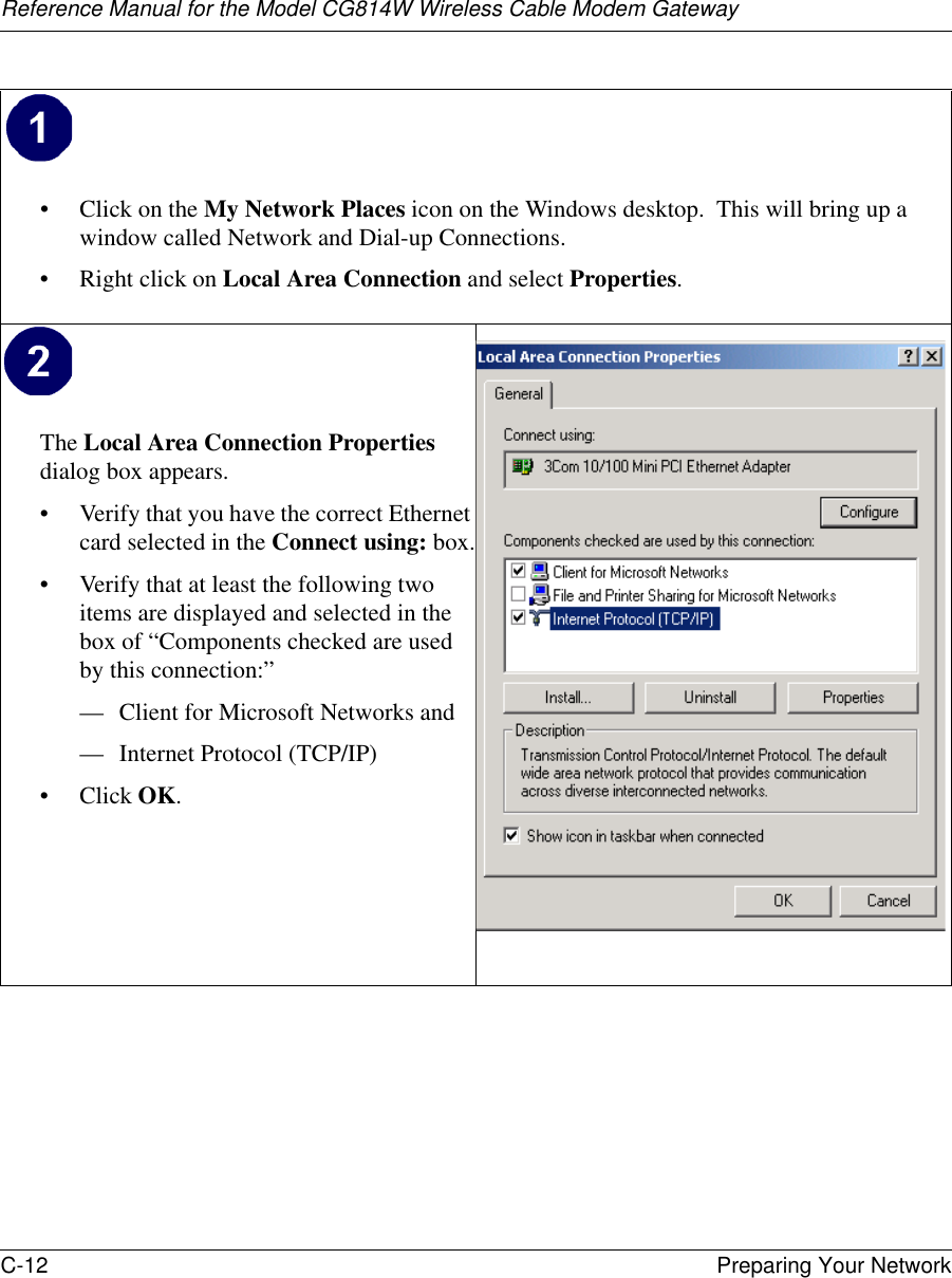
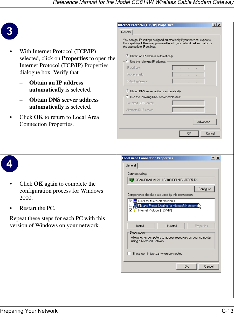
![Reference Manual for the Model CG814W Wireless Cable Modem GatewayAbout This Manual ix About This ManualThank your for purchasing the NETGEAR™ CG814W Wireless Cable Modem Gateway. This manual describes the features of the gateway and provides installation and configuration instructions.AudienceThis reference manual assumes that the reader has basic to intermediate computer and Internet skills. However, basic computer network, Internet, firewall, and PC networking technologies tutorial information is provided in the Appendices.Typographical ConventionsThis guide uses the following typographical conventions:italics Media titles, UNIX files, commands, URLs, and directory names.bold times roman User inputInternet Protocol (IP) First time an abbreviated term is used.courier font Screen text, user-typed command-line entries.[Enter] Named keys in text are shown enclosed in square brackets. The notation [Enter] is used for the Enter key and the Return key.[Ctrl]+C Two or more keys that must be pressed simultaneously are shown in text linked with a plus (+) sign.ALL CAPS DOS file and directory names.](https://usermanual.wiki/Netgear-orporated/CG814WG/User-Guide-361276-Page-9.png)