Netgear orporated DG834GV2 Wireless ADSL Firewall Router User Manual FullManual
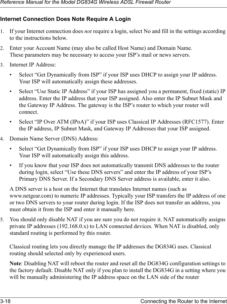
Netgear Incorporated Wireless ADSL Firewall Router FullManual
UserManual.wiki
>
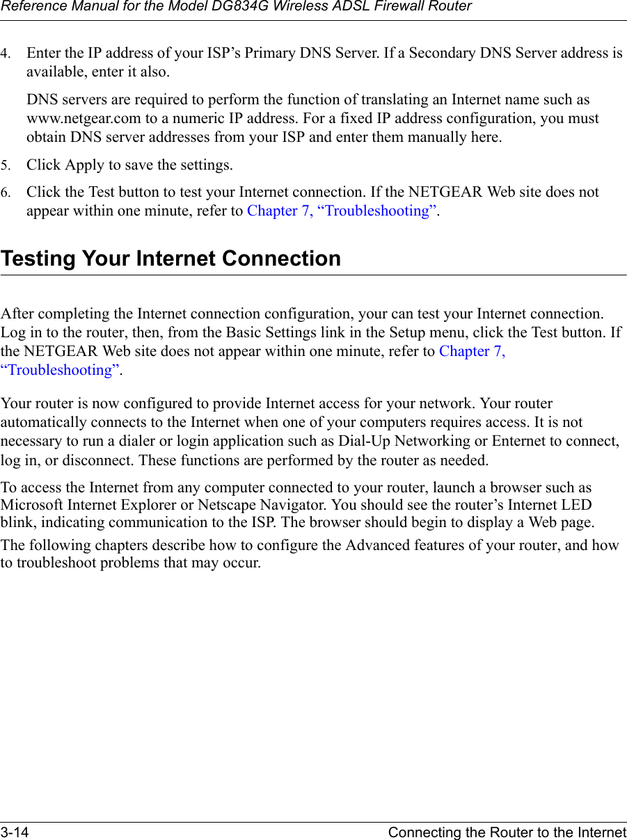
Netgear orporated
>
DG834GV2 User Manual
Users Manual
Navigation menu
Upload a User Manual
Namespaces
Wiki Guide
HTML
PDF
Info
Views
User Manual
Discussion / Help
Navigation


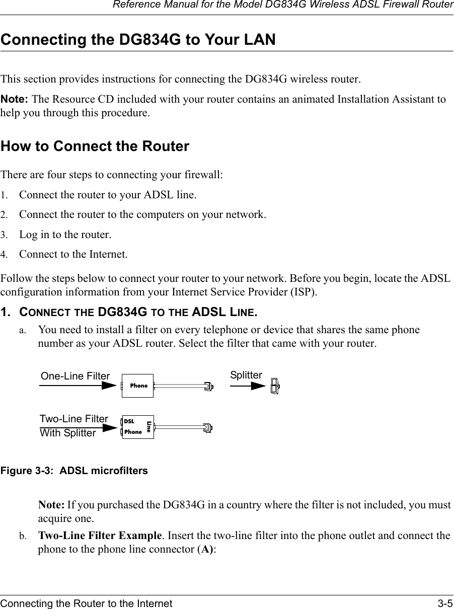
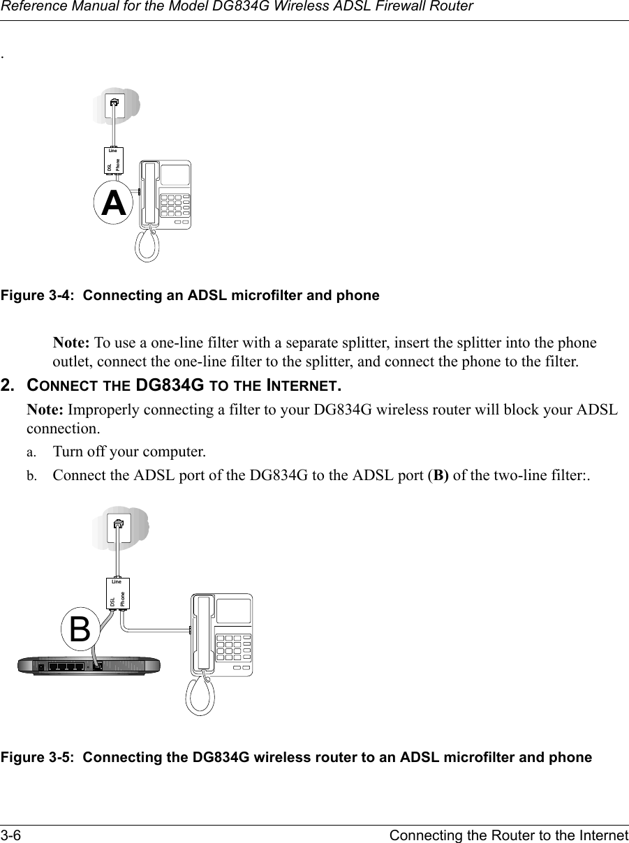

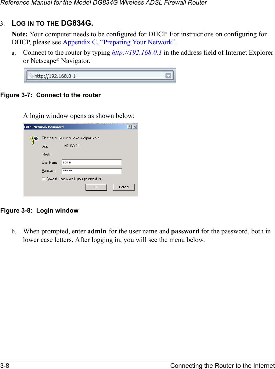
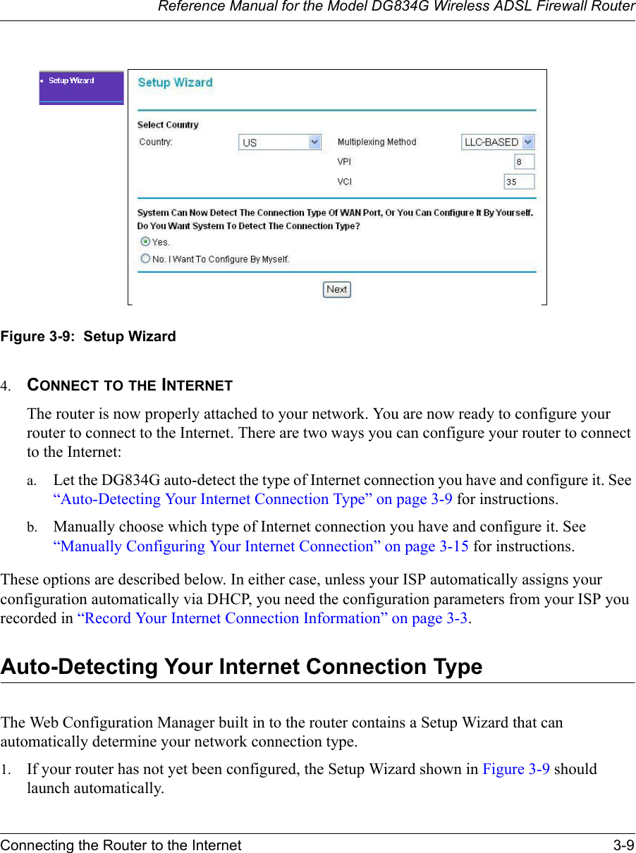


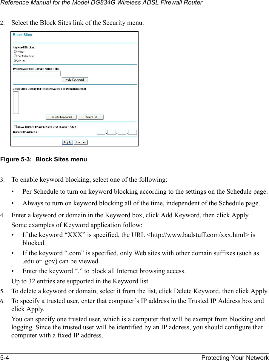
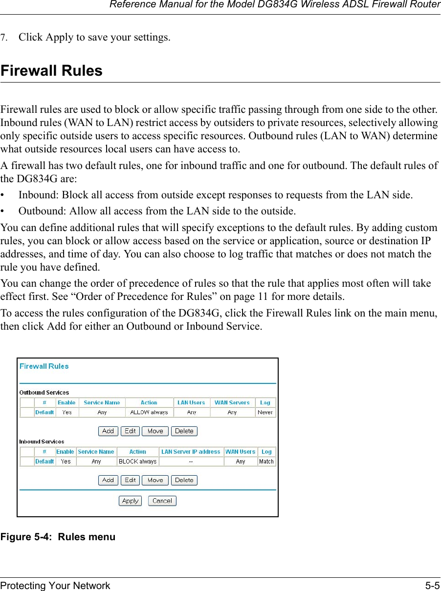

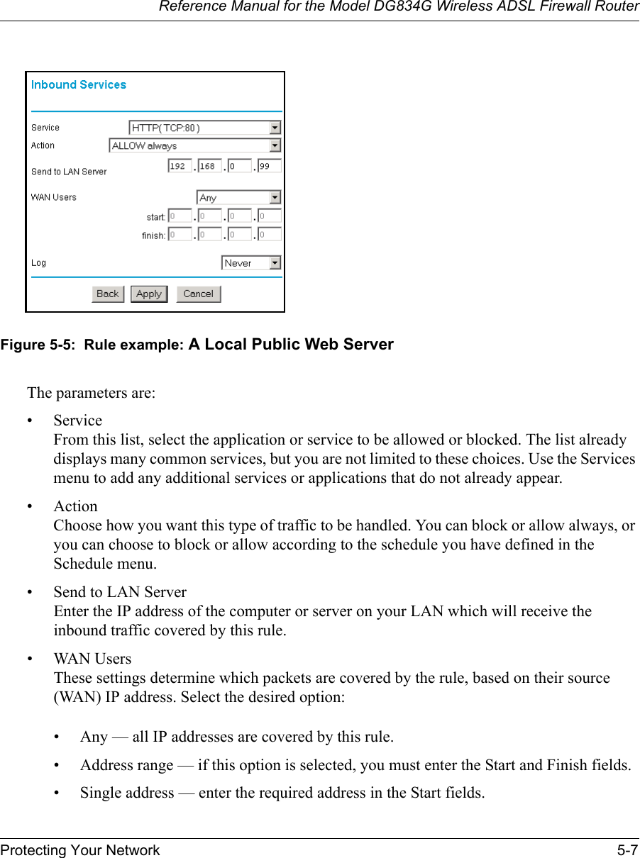
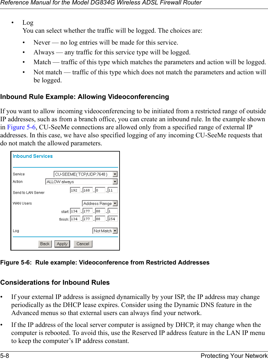
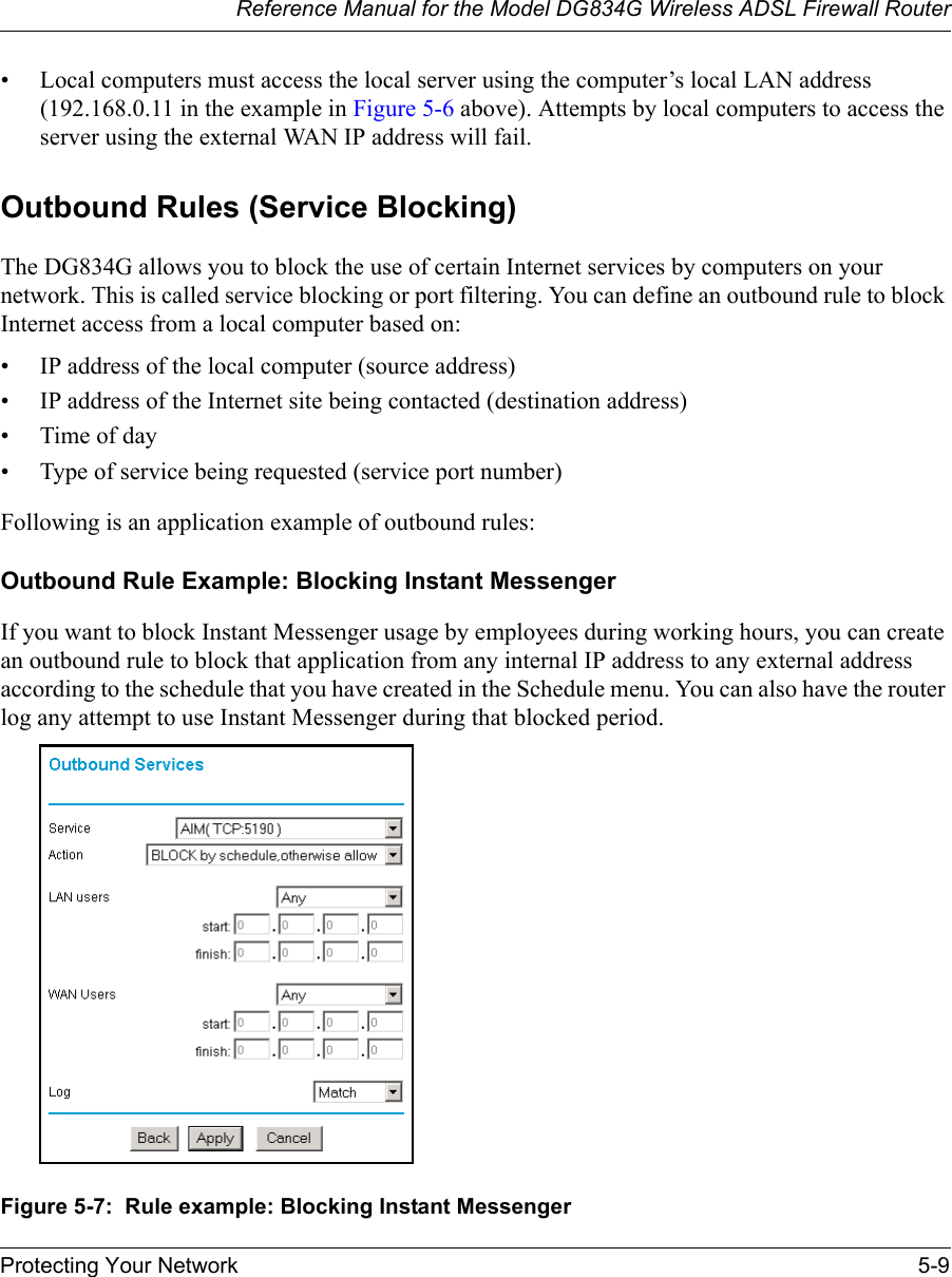
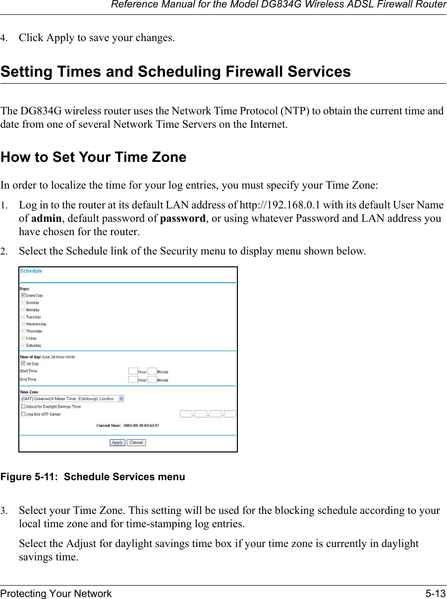


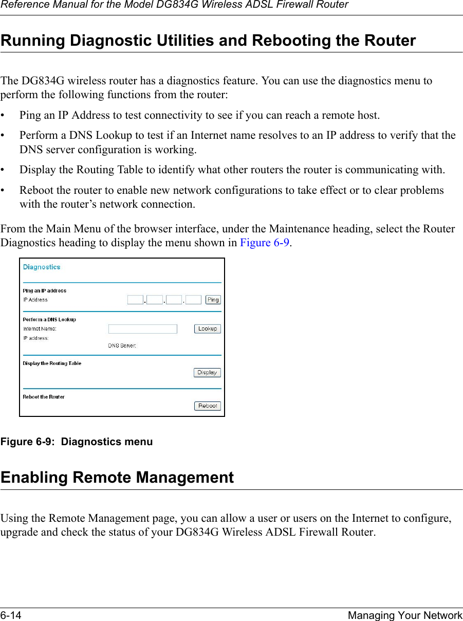
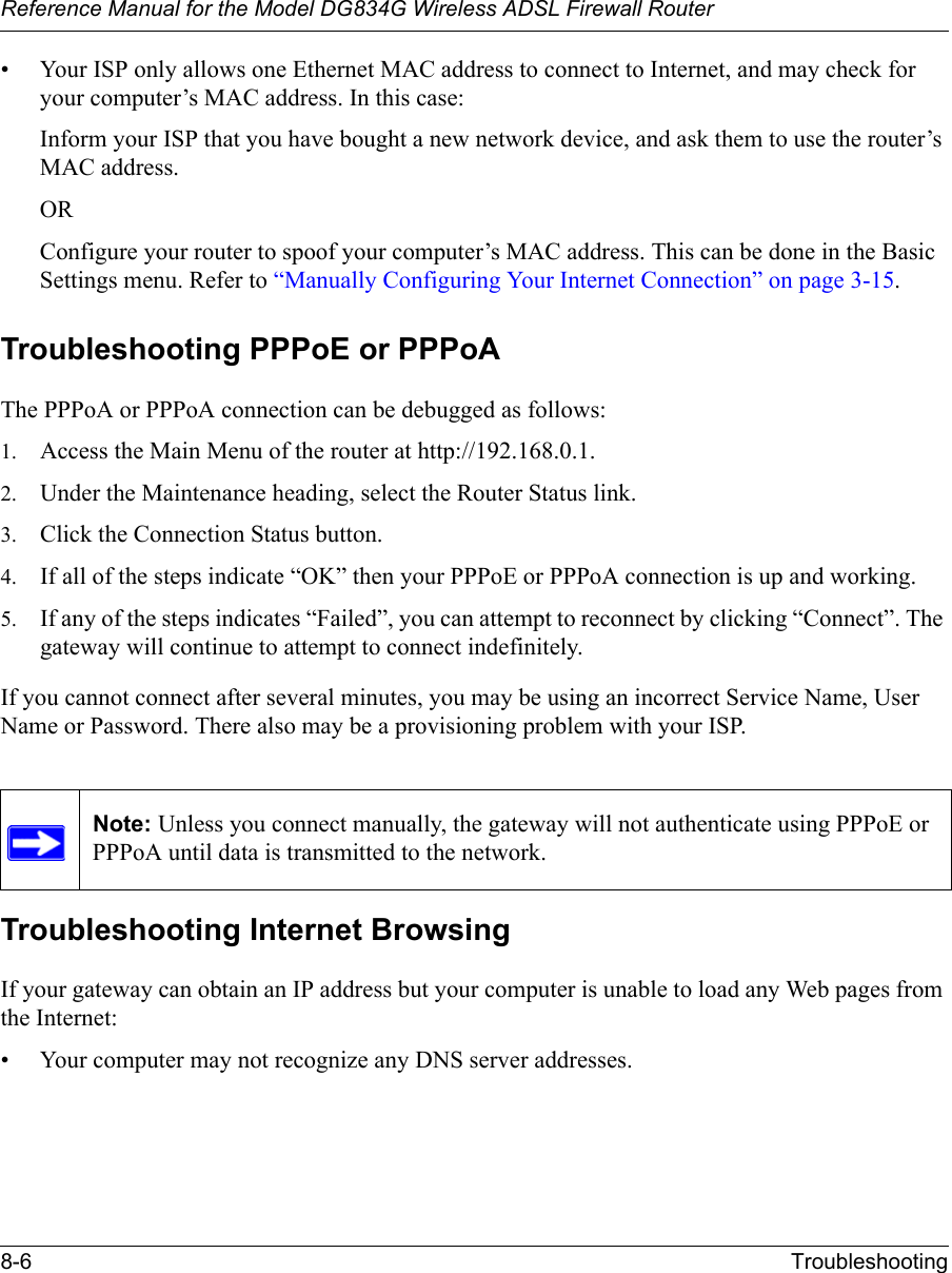
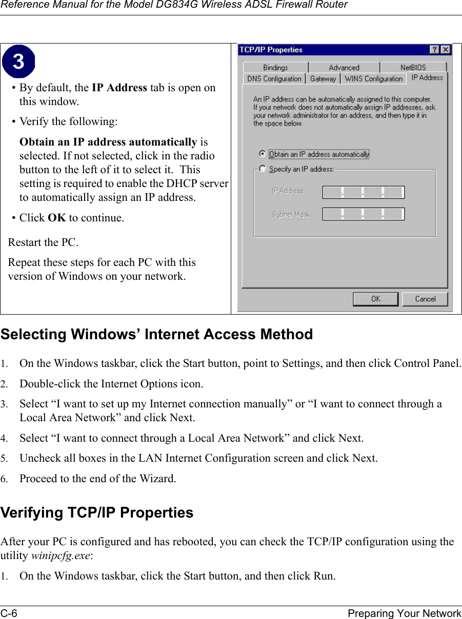
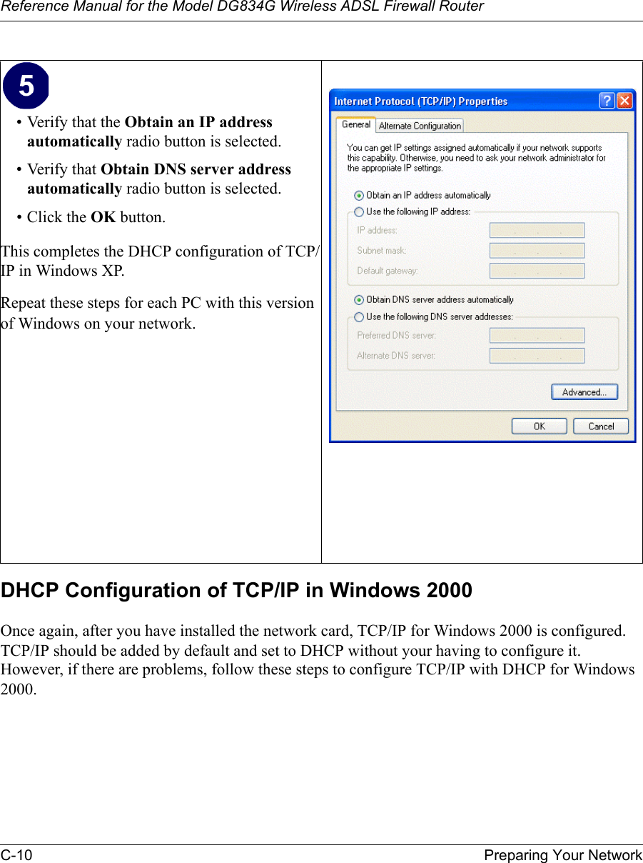
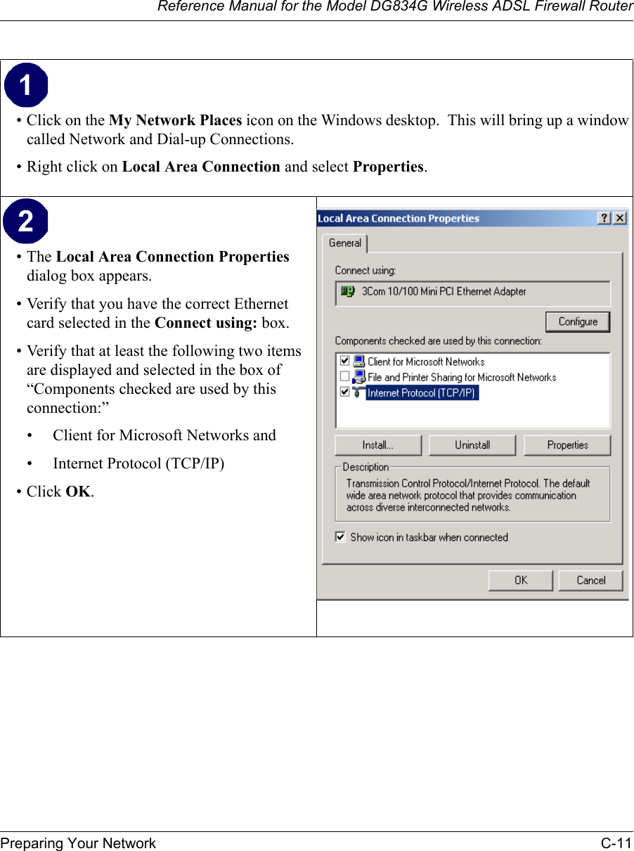
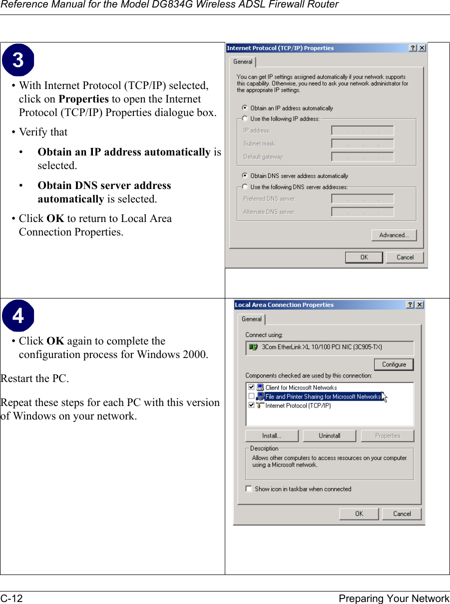
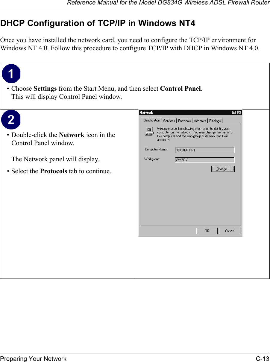
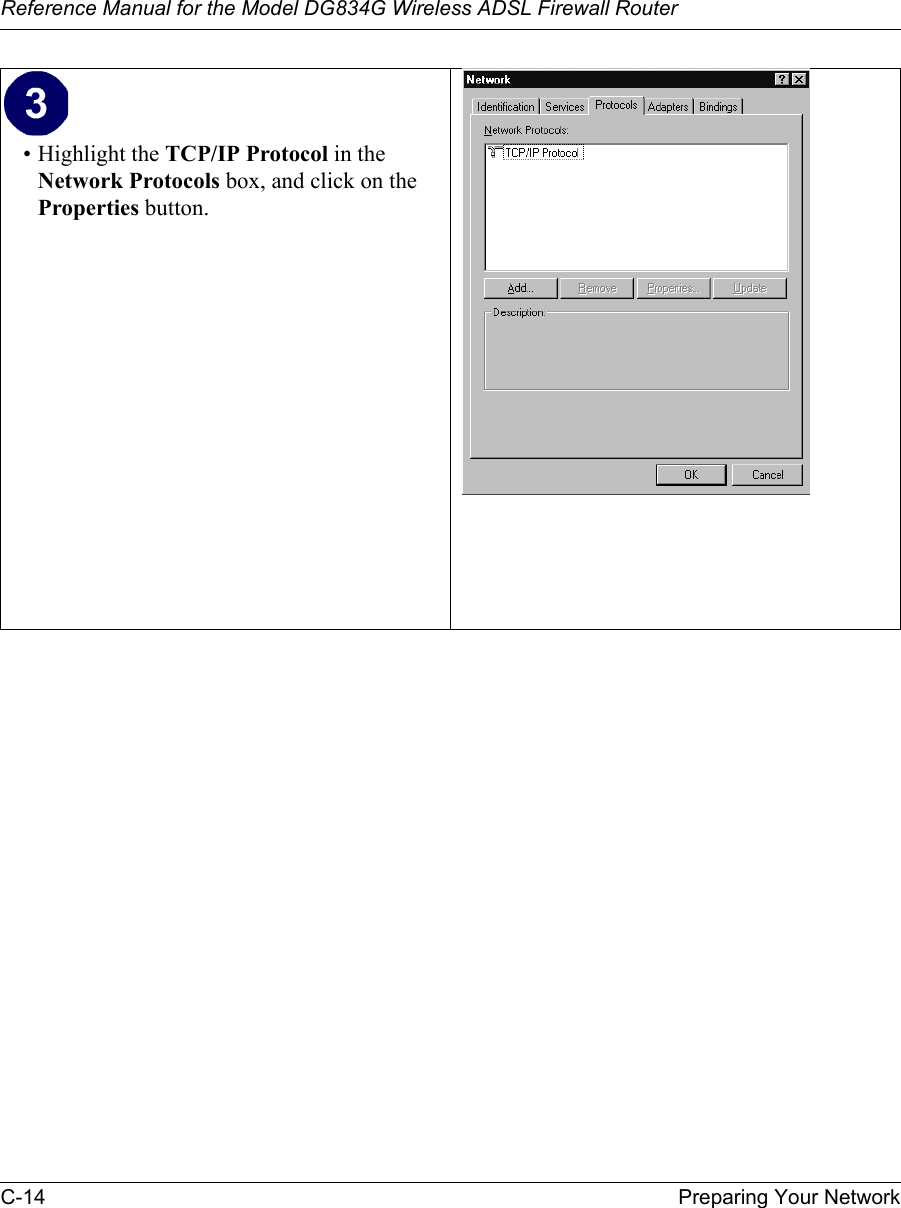
![Reference Manual for the Model DG834G Wireless ADSL Firewall Router6-12 Managing Your Network Saving Log Files on a ServerYou can choose to write the logs to a computer running a syslog program. To activate this feature, select to Broadcast Lan or enter the IP address of the server where the Syslog file will be written.Examples of Log MessagesFollowing are examples of log messages. In all cases, the log entry shows the timestamp as: Day, Year-Month-Date Hour:Minute:SecondActivation and AdministrationTue, 2002-05-21 18:48:39 - NETGEAR activated [This entry indicates a power-up or reboot with initial time entry.]Tue, 2002-05-21 18:55:00 - Administrator login successful - IP:192.168.0.2 Thu, 2002-05-21 18:56:58 - Administrator logout - IP:192.168.0.2 [This entry shows an administrator logging in and out from IP address 192.168.0.2.]Tue, 2002-05-21 19:00:06 - Login screen timed out - IP:192.168.0.2[This entry shows a time-out of the administrator login.]Wed, 2002-05-22 22:00:19 - Log emailed[This entry shows when the log was emailed.]Dropped Packets Wed, 2002-05-22 07:15:15 - TCP packet dropped - Source:64.12.47.28,4787,WAN - Destination:134.177.0.11,21,LAN - [Inbound Default rule match]Sun, 2002-05-22 12:50:33 - UDP packet dropped - Source:64.12.47.28,10714,WAN - Destination:134.177.0.11,6970,LAN - [Inbound Default rule match]Sun, 2002-05-22 21:02:53 - ICMP packet dropped - Source:64.12.47.28,0,WAN - Destination:134.177.0.11,0,LAN - [Inbound Default rule match][These entries show an inbound FTP (port 21) packet, User Datagram Protocol (UDP) packet (port 6970), and Internet Control Message Protocol (ICMP) packet (port 0) being dropped as a result of the default inbound rule, which states that all inbound packets are denied.]](https://usermanual.wiki/Netgear-orporated/DG834GV2/User-Guide-450691-Page-82.png)