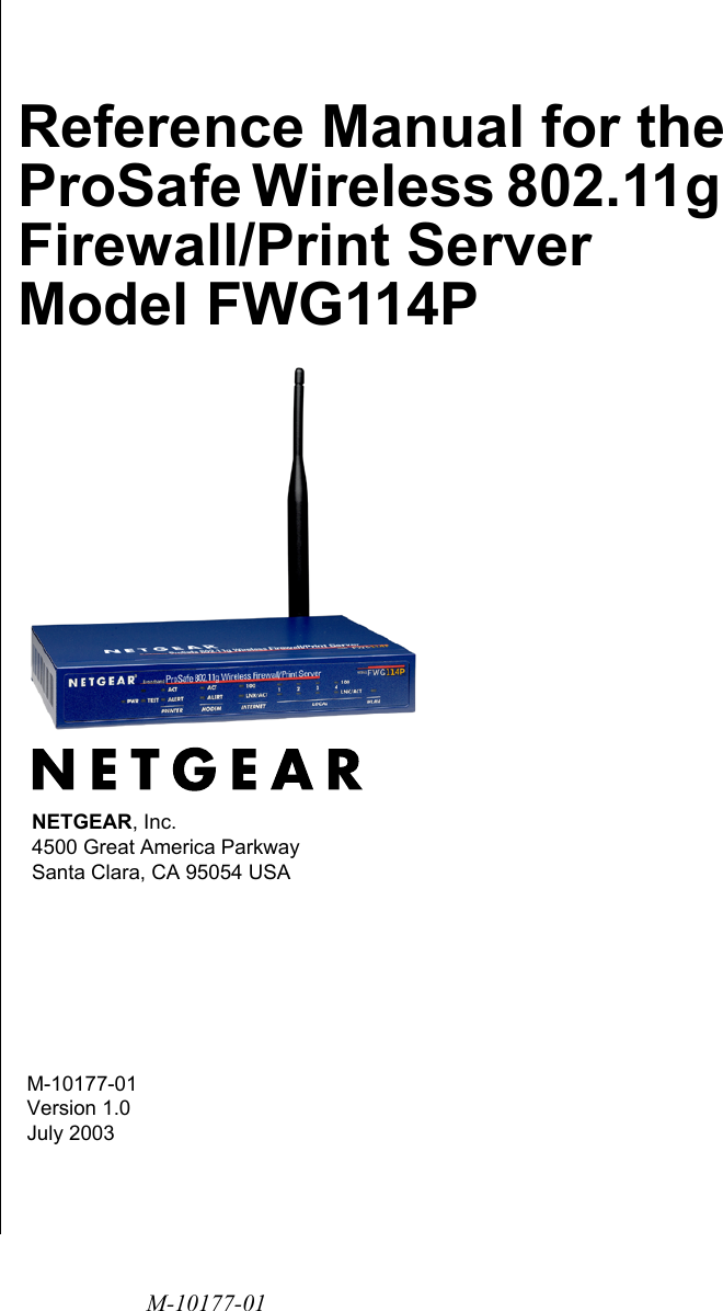
Netgear orporated FWG114P WIRELESS FIREWALL User Manual FullManual

Netgear Incorporated WIRELESS FIREWALL FullManual

Contents

USERS MANUAL 1

M-10177-01M-10177-01 Version 1.0July 2003NETGEAR, Inc.4500 Great America Parkway Santa Clara, CA 95054 USAReference Manual for the ProSafe Wireless 802.11g  Firewall/Print Server Model FWG114P
iiM-10177-01© 2003 by NETGEAR, Inc. All rights reserved.TrademarksNETGEAR is a trademark of Netgear, Inc. Microsoft, Windows, and Windows NT are registered trademarks of Microsoft Corporation.Other brand and product names are registered trademarks or trademarks of their respective holders.Statement of ConditionsIn the interest of improving internal design, operational function, and/or reliability, NETGEAR reserves the right to make changes to the products described in this document without notice.NETGEAR does not assume any liability that may occur due to the use or application of the product(s) or circuit layout(s) described herein.Federal Communications Commission (FCC) Compliance Notice: Radio Frequency NoticeThis equipment has been tested and found to comply with the limits for a Class B digital device, pursuant to  part 15 of the FCC Rules. These limits are designed to provide reasonable protection against harmful interference in a residential installation. This equipment generates, uses, and can radiate radio frequency energy and, if not installed and used in accordance with the instructions, may cause harmful interference to radio communications. However, there is no guarantee that interference will not occur in a particular installation. If this equipment does cause harmful interference to radio or television reception, which can be determined by turning the equipment off and on, the user is encouraged to try to correct the interference by one or more of the following measures:• Reorient or relocate the receiving antenna.• Increase the separation between the equipment and receiver.• Connect the equipment into an outlet on a circuit different from that to which the receiver is connected.• Consult the dealer or an experienced radio/TV technician for help. FCC Caution1. FCC RF Radiation Exposure Statement: The equipment complies with FCC RF radiation exposure limits set forth for an uncontrolled environment. This equipment should be installed and operated with a minimum distance of 20 centimeters between the radiator and your body. 2. This Transmitter must not be co-located or operating in conjunction with any other antenna or transmitter. 3. Changes or modifications to this unit not expressly approved by the party responsible for compliance could void the user authority to operate the equipment.EN 55 022 Declaration of ConformanceThis is to certify that the ProSafe Wireless 802.11g  Firewall/Print Server Model FWG114P is shielded against the generation of radio interference in accordance with the application of Council Directive 89/336/EEC, Article 4a. Conformity is declared by the application of EN 55 022 Class B (CISPR 22).
M-10177-01iiiBestätigung des Herstellers/ImporteursEs wird hiermit bestätigt, daß das ProSafe Wireless 802.11g  Firewall/Print Server Model FWG114P gemäß der im BMPT-AmtsblVfg 243/1991 und Vfg 46/1992 aufgeführten Bestimmungen entstört ist. Das vorschriftsmäßige Betreiben einiger Geräte (z.B. Testsender) kann jedoch gewissen Beschränkungen unterliegen. Lesen Sie dazu bitte die Anmerkungen in der Betriebsanleitung.Das Bundesamt für Zulassungen in der Telekommunikation wurde davon unterrichtet, daß dieses Gerät auf den Markt gebracht wurde und es ist berechtigt, die Serie auf die Erfüllung der Vorschriften hin zu überprüfen.Certificate of the Manufacturer/ImporterIt is hereby certified that the ProSafe Wireless 802.11g  Firewall/Print Server Model FWG114P has been suppressed in accordance with the conditions set out in the BMPT-AmtsblVfg 243/1991 and Vfg 46/1992. The operation of some equipment (for example, test transmitters) in accordance with the regulations may, however, be subject to certain restrictions. Please refer to the notes in the operating instructions. Federal Office for Telecommunications Approvals has been notified of the placing of this equipment on the market and has been granted the right to test the series for compliance with the regulations. Voluntary Control Council for Interference (VCCI) StatementThis equipment is in the second category (information equipment to be used in a residential area or an adjacent area thereto) and conforms to the standards set by the Voluntary Control Council for Interference by Data Processing Equipment and Electronic Office Machines aimed at preventing radio interference in such residential areas.When used near a radio or TV receiver, it may become the cause of radio interference. Read instructions for correct handling.
M-10177-01iv
Contents vM-10177-01ContentsChapter 1  About This ManualAudience, Conventions, Scope  ......................................................................................1-1Features of the HTML Version of this Manual  ................................................................1-2How to Print this Manual .................................................................................................1-3Chapter 2  IntroductionKey Features of the FWG114P .......................................................................................2-1802.11g and 802.11b Wireless Networking ..............................................................2-2A Powerful, True Firewall with Content Filtering  ......................................................2-2Security ....................................................................................................................2-3Autosensing Ethernet Connections with Auto Uplink  ...............................................2-3Extensive Protocol Support ......................................................................................2-3Easy Installation and Management  ..........................................................................2-4Maintenance and Support ........................................................................................2-5Package Contents  ..........................................................................................................2-5The FWG114P Front Panel ......................................................................................2-6The FWG114P Rear Panel  ......................................................................................2-8Chapter 3  Connecting the FWG114P to the InternetWhat You Will Need Before You Begin ...........................................................................3-1Cabling and Computer Hardware Requirements .....................................................3-1Computer Network Configuration Requirements  .....................................................3-1Internet Configuration Requirements .......................................................................3-2Where Do I Get the Internet Configuration Parameters? .........................................3-2Record Your Internet Connection Information ..........................................................3-3Connecting the FWG114P Wireless Firewall/Print Server ..............................................3-4How to Connect the FWG114P  ................................................................................3-4PPPoE Wizard-Detected Option  ..............................................................................3-8
M-10177-01vi ContentsDynamic IP Wizard-Detected Option  .......................................................................3-9Fixed IP Account Wizard-Detected Option .............................................................3-10Manually Configuring Your Internet Connection  ........................................................... 3-11How to Configure the Internet Connection Manually ..............................................3-12How to Configure a Serial Port Internet Connection .....................................................3-13Chapter 4  Wireless ConfigurationObserve Performance, Placement, and Range Guidelines ............................................4-1Implement Appropriate Wireless Security  ......................................................................4-2Understanding Wireless Settings ...................................................................................4-3Default Factory Settings ...........................................................................................4-6Before You Change the SSID and WEP Settings  ....................................................4-6How to Set Up and Test Basic Wireless Connectivity ..............................................4-7How to Restrict Wireless Access by MAC Address .................................................4-8How to Configure WEP  ............................................................................................4-9Chapter 5  Firewall Protection and  Content FilteringFirewall Protection and Content Filtering Overview ........................................................5-1Block Sites ......................................................................................................................5-2Using Rules to Block or Allow Specific Kinds of Traffic  ..................................................5-3Inbound Rules (Port Forwarding) .............................................................................5-5Inbound Rule Example: A Local Public Web Server ..........................................5-6Inbound Rule Example: Allowing Videoconference from Restricted Addresses 5-6Considerations for Inbound Rules .....................................................................5-7Outbound Rules (Service Blocking)  .........................................................................5-7Outbound Rule Example: Blocking Instant Messenger  .....................................5-8Order of Precedence for Rules ................................................................................5-8Rules Menu Options .................................................................................................5-9Services ........................................................................................................................5-10Using a Schedule to Block or Allow Specific Traffic ...................................................... 5-11Time Zone ........................................................................................................5-12Getting E-Mail Notifications of Event Logs and Alerts  ..................................................5-13Viewing Logs of Web Access or Attempted Web Access .............................................5-15Include in Log .........................................................................................................5-16Syslog ....................................................................................................................5-17
Contents viiM-10177-01Chapter 6  Print ServerNetwork Printing from Windows  .....................................................................................6-1Installing the PTP Driver  ..........................................................................................6-1Printer Management  ..........................................................................................6-3Port Options .......................................................................................................6-3LPD/LPR Printing from Windows  .............................................................................6-4Windows NT 4.0 Server Configuration  ..............................................................6-5Client PC Setup for LPD/LPR Printing ...............................................................6-7Network Printing from the Macintosh ..............................................................................6-8Network Printing from Linux  ...........................................................................................6-9Troubleshooting the Print Server  ....................................................................................6-9Chapter 7  MaintenanceViewing Wireless Firewall/Print Server Status Information .............................................5-1Viewing a List of Attached Devices .................................................................................5-5Upgrading the Router Software ......................................................................................5-5Configuration File Management  .....................................................................................5-6Restoring and Backing Up the Configuration  ...........................................................5-7Erasing the Configuration .........................................................................................5-8Changing the Administrator Password ...........................................................................5-8Chapter 8  Advanced ConfigurationUsing the WAN Setup Options  .......................................................................................6-1How to Configure Dynamic DNS  ....................................................................................6-3Using the LAN IP Setup Options  ....................................................................................6-5Configuring LAN TCP/IP Setup Parameters  ............................................................6-5Using the Router as a DHCP server  ........................................................................6-6Using Address Reservation ......................................................................................6-7Configuring Static Routes  ...............................................................................................6-8Enabling Remote Management Access  .......................................................................6-10Using Universal Plug and Play (UPnP)  ........................................................................ 6-11Chapter 9  TroubleshootingBasic Functioning  ...........................................................................................................7-1Power LED Not On ...................................................................................................7-1
M-10177-01viii ContentsLEDs Never Turn Off ................................................................................................7-2LAN or Internet Port LEDs Not On  ...........................................................................7-2Troubleshooting the Web Configuration Interface  ..........................................................7-3Troubleshooting the ISP Connection  ..............................................................................7-4Troubleshooting a TCP/IP Network Using a Ping Utility  .................................................7-5Testing the LAN Path to Your Router  .......................................................................7-5Testing the Path from Your PC to a Remote Device  ................................................7-6Restoring the Default Configuration and Password ........................................................7-7Problems with Date and Time .........................................................................................7-7Appendix A  Technical SpecificationsAppendix B  Networks, Routing, and Firewall BasicsRelated Publications ...................................................................................................... B-1Basic Router Concepts .................................................................................................. B-1What is a Router?  ................................................................................................... B-1Routing Information Protocol ................................................................................... B-2IP Addresses and the Internet ................................................................................. B-2Netmask .................................................................................................................. B-4Subnet Addressing .................................................................................................. B-4Private IP Addresses ............................................................................................... B-7Single IP Address Operation Using NAT ................................................................. B-8MAC Addresses and Address Resolution Protocol ................................................. B-9Related Documents ................................................................................................. B-9Domain Name Server .............................................................................................. B-9IP Configuration by DHCP  .................................................................................... B-10Internet Security and Firewalls .................................................................................... B-10What is a Firewall? .................................................................................................B-11Stateful Packet Inspection ......................................................................................B-11Denial of Service Attack  .........................................................................................B-11Ethernet Cabling ...........................................................................................................B-11Category 5 Cable Quality  ...................................................................................... B-12Inside Twisted Pair Cables .................................................................................... B-13Uplink Switches, Crossover Cables, and MDI/MDIX Switching  ............................ B-14
Contents ixM-10177-01Appendix C  Preparing Your NetworkPreparing Your Computers for TCP/IP Networking  ....................................................... C-1Configuring Windows 95, 98, and Me for TCP/IP Networking ....................................... C-2Install or Verify Windows Networking Components ................................................. C-2Enabling DHCP to Automatically Configure TCP/IP Settings  ................................. C-4Selecting Windows’ Internet Access Method .......................................................... C-6Verifying TCP/IP Properties  .................................................................................... C-6Configuring Windows NT4, 2000 or XP for IP Networking  ............................................ C-7Install or Verify Windows Networking Components ................................................. C-7Enabling DHCP to Automatically Configure TCP/IP Settings  ................................. C-8DHCP Configuration of TCP/IP in Windows XP  ..................................................... C-8DHCP Configuration of TCP/IP in Windows 2000  ................................................ C-10DHCP Configuration of TCP/IP in Windows NT4 .................................................. C-13Verifying TCP/IP Properties for Windows XP, 2000, and NT4  .............................. C-15Configuring the Macintosh for TCP/IP Networking ...................................................... C-16MacOS 8.6 or 9.x  .................................................................................................. C-16MacOS X ............................................................................................................... C-16Verifying TCP/IP Properties for Macintosh Computers  ......................................... C-17Verifying the Readiness of Your Internet Account ....................................................... C-18Are Login Protocols Used?  ................................................................................... C-18What Is Your Configuration Information?  .............................................................. C-18Obtaining ISP Configuration Information for Windows Computers  ....................... C-19Obtaining ISP Configuration Information for Macintosh Computers  ..................... C-20Restarting the Network  ................................................................................................ C-21Appendix D  Wireless Networking BasicsWireless Networking Overview ...................................................................................... D-1Infrastructure Mode  ................................................................................................. D-1Ad Hoc Mode (Peer-to-Peer Workgroup) ................................................................ D-2Network Name: Extended Service Set Identification (ESSID) ................................ D-2Authentication and WEP Data Encryption  ..................................................................... D-3802.11 Authentication .............................................................................................. D-3Open System Authentication ................................................................................... D-4Shared Key Authentication ...................................................................................... D-4
M-10177-01xContentsOverview of WEP Parameters  ................................................................................ D-5Key Size  .................................................................................................................. D-6WEP Configuration Options  .................................................................................... D-7Wireless Channels ......................................................................................................... D-7 GlossaryList of Glossary Terms  ................................................................................................... G-1 Index
About This Manual 1M-10177-01Chapter 1 About This ManualCongratulations on your purchase of the NETGEAR® ProSafe Wireless 802.11g  Firewall/Print Server Model FWG114P. This chapter introduces important features of this manual.Audience, Conventions, Scope This reference manual assumes that the reader has basic-to-intermediate computer and Internet skills. However, basic computer network, Internet, firewall, and networking technology tutorial information is provided in the Appendices.This guide uses the following typographical conventions:This guide uses the following formats to highlight special messages: This manual is written f according to these specifications.:Table 1. Typographical conventionsitalics Emphasis, books, CDs, URL namesbold times roman User inputcourier font Screen text, file and server names, extensions, commands, IP addressesNote: This format is used to highlight information of importance or special interest.Table 1-1. Manual SpecificationsProduct Version ProSafe Wireless 802.11g  Firewall/Print Server Model FWG114PManual Publication Date July 2003Note: Product updates are available on the NETGEAR, Inc. web site at http://www.netgear.com/support/main.asp. Documentation updates are available on the NETGEAR, Inc. web site at http://www.netgear.com/docs.
Reference Manual for the ProSafe Wireless 802.11g  Firewall/Print Server Model FWG114P2About This ManualM-10177-01Features of the HTML Version of this ManualThe HTML version of this manual includes these features.Figure Preface -2:  HTML version of this manual1. Left pane. Use the left pane to view the Contents, Index, Search, and Favorites tabs. To view the HTML version of the manual, you must have a version 4 or later browser with Java or JavaScript enabled. To use the Favorites feature, your browser must be set to accept cookies. You can record a list of favorite pages in the manual for easy later retrieval.2. Toolbar buttons. Use the toolbar buttons across the top to navigate, print pages, and more.–The Show in Contents button locates the currently displayed topic in the Contents tab.–Previous/Next buttons display the topic that precedes or follows the current topic.–The PDF button links to a PDF version of the full manual.–The E-mail button enables you to send feedback by e-mail to Netgear support. –The Print button prints the currently displayed topic. Using this button when a step-by-step procedure is displayed will send the entire procedure to your printer--you do not have to worry about specifying the correct range of pages.–The Bookmark button bookmarks the currently displayed page in your browser.3. Right pane. Use the right pane to view the contents of the manual. Also, each page of the manual includes a “PDF of This Chapter” link at the top right which links to a PDF file containing just the currently selected chapter of the manual.123
Reference Manual for the ProSafe Wireless 802.11g  Firewall/Print Server Model FWG114PAbout This Manual 3M-10177-01How to Print this ManualTo print this manual you man choose one of the following several options, according to your needs.•Printing a “How To” Sequence of Steps in the HTML View. Use the Print button on the upper right of the toolbar to print the currently displayed topic. Using this button when a step-by-step procedure is displayed will send the entire procedure to your printer--you do not have to worry about specifying the correct range of pages. •Printing a Chapter. Use the “PDF of This Chapter” link at the top right of any page.– Click “PDF of This Chapter” link at the top right of any page in the chapter you want to print. A new browser window opens showing the PDF version of the chapter you were viewing. – Click the print icon in the upper left of the window. –Tip: If your printer supports printing two pages on a single sheet of paper, you can save paper an printer ink by selecting this feature.•Printing the Full Manual. Use the PDF button in the toolbar at the top right of the browser window.– Click PDF button. A new browser window opens showing the PDF version of the chapter you were viewing. – Click the print icon in the upper left of the window. –Tip: If your printer supports printing two pages on a single sheet of paper, you can save paper an printer ink by selecting this feature.
Reference Manual for the ProSafe Wireless 802.11g  Firewall/Print Server Model FWG114P4About This ManualM-10177-01
Introduction 2-1M-10177-01Chapter 2 IntroductionThis chapter describes the features of the NETGEAR ProSafe Wireless 802.11g  Firewall/Print Server Model FWG114P.Key Features of the FWG114PThe ProSafe Wireless 802.11g  Firewall/Print Server Model FWG114P with 4-port switch connects your LAN to the Internet through a broadband modem. With auto fail-over connectivity through the serial port, the FWG114P provides highly reliable Internet access. The FWG114P is a complete security solution that protects your network from attacks and intrusions. Unlike simple Internet sharing routers that rely on Network Address Translation (NAT) for security, the FWG114P uses Stateful Packet Inspection for Denial of Service attack (DoS) attack protection and intrusion detection. The FWG114P allows Internet access for up to 253 users. The FWG114P Wireless Firewall/Print Server provides you with multiple Web content filtering options, plus browsing activity reporting and instant alerts -- both via e-mail. Parents and network administrators can establish restricted access policies based on time-of-day, Website addresses and address keywords, and share high-speed cable/DSL Internet access for up to 253 personal computers. In addition to NAT, the built-in firewall protects you from hackers.With minimum setup, you can install and use the router within minutes. The FWG114P Wireless Firewall/Print Server provides the following features:• 802.11g and 802.11b standards-based wireless networking.• Easy, web-based setup for installation and management.• Content Filtering and Site Blocking Security.• Built in 4-port 10/100 Mbps Switch.• Ethernet connection to a WAN device, such as a cable modem or DSL modem.• Extensive Protocol Support.• Login capability.• Front panel LEDs for easy monitoring of status and activity.• Flash memory for firmware upgrade.
Reference Manual for the ProSafe Wireless 802.11g  Firewall/Print Server Model FWG114P2-2 IntroductionM-10177-01802.11g and 802.11b Wireless NetworkingThe FWG114P Wireless Firewall/Print Server includes an 802.11b-compliant wireless access point, providing continuous, high-speed 11 Mbps access between your wireless and Ethernet devices. The access point provides:• 802.11b Standards-based wireless networking at up to 11 Mbps.• 802.11g wireless networking at up to 54 Mbps, which conform to the 802.11g standard.• 64-bit and 128-bit WEP encryption security.• WEP keys can be generated manually or by passphrase.• Wireless access can be restricted by MAC address.• Wireless network name broadcast can be turned off so that only devices that have the network name (SSID) can connect.A Powerful, True Firewall with Content FilteringUnlike simple Internet sharing NAT routers, the FWG114P is a true firewall, using stateful packet inspection to defend against hacker attacks. Its firewall features include:• DoS protection.Automatically detects and thwarts DoS attacks such as Ping of Death, SYN Flood, LAND Attack, and IP Spoofing.• Blocks unwanted traffic from the Internet to your LAN.• Blocks access from your LAN to Internet locations or services that you specify as off-limits.• Logs security incidents.The FWG114P will log security events such as blocked incoming traffic, port scans, attacks, and administrator logins. You can configure the router to email the log to you at specified intervals. You can also configure the router to send immediate alert messages to your email address or email pager whenever a significant event occurs.• With its content filtering feature, the FWG114P prevents objectionable content from reaching your PCs. The router allows you to control access to Internet content by screening for keywords within Web addresses. You can configure the router to log and report attempts to access objectionable Internet sites.
Reference Manual for the ProSafe Wireless 802.11g  Firewall/Print Server Model FWG114PIntroduction 2-3M-10177-01SecurityThe FWG114P Wireless Firewall/Print Server is equipped with several features designed to maintain security, as described in this section.• PCs Hidden by NAT: NAT opens a temporary path to the Internet for requests originating from the local network. Requests originating from outside the LAN are discarded, preventing users outside the LAN from finding and directly accessing the PCs on the LAN.• Port Forwarding with NAT: Although NAT prevents Internet locations from directly accessing the PCs on the LAN, the router allows you to direct incoming traffic to specific PCs based on the service port number of the incoming request, or to one designated “DNS” host computer. You can specify forwarding of single ports or ranges of ports.Autosensing Ethernet Connections with Auto Uplink With its internal 8-port 10/100 switch, the FWG114P can connect to either a 10 Mbps standard Ethernet network or a 100 Mbps Fast Ethernet network. Both the LAN and WAN interfaces are autosensing and capable of full-duplex or half-duplex operation. The router incorporates Auto UplinkTM technology. Each Ethernet port will automatically sense whether the Ethernet cable plugged into the port should have a ‘normal’ connection such as to a PC or an ‘uplink’ connection such as to a switch or hub. That port will then configure itself to the correct configuration. This feature also eliminates the need to worry about crossover cables, as Auto Uplink will accommodate either type of cable to make the right connection.Extensive Protocol SupportThe FWG114P Wireless Firewall/Print Server supports the Transmission Control Protocol/Internet Protocol (TCP/IP) and Routing Information Protocol (RIP). For further information about TCP/IP, refer to Appendix B, “Network, Routing, Firewall, and Basics.”• IP Address Sharing by NAT: The FWG114P Wireless Firewall/Print Server allows several networked PCs to share an Internet account using only a single IP address, which may be statically or dynamically assigned by your Internet service provider (ISP). This technique, known as NAT, allows the use of an inexpensive single-user ISP account.
Reference Manual for the ProSafe Wireless 802.11g  Firewall/Print Server Model FWG114P2-4 IntroductionM-10177-01• Automatic Configuration of Attached PCs by DHCP: The FWG114P Wireless Firewall/Print Server dynamically assigns network configuration information, including IP, gateway, and domain name server (DNS) addresses, to attached PCs on the LAN using the Dynamic Host Configuration Protocol (DHCP). This feature greatly simplifies configuration of PCs on your local network.• DNS Proxy: When DHCP is enabled and no DNS addresses are specified, the router provides its own address as a DNS server to the attached PCs. The router obtains actual DNS addresses from the ISP during connection setup and forwards DNS requests from the LAN.• PPP over Ethernet (PPPoE): PPPoE is a protocol for connecting remote hosts to the Internet over a DSL connection by simulating a dial-up connection. This feature eliminates the need to run a login program such as Entersys or WinPOET on your PC.• PPTP login support for European ISPs, BigPond login for Telstra cable in Australia.Easy Installation and ManagementYou can install, configure, and operate the ProSafe Wireless 802.11g  Firewall/Print Server Model FWG114P within minutes after connecting it to the network. The following features simplify installation and management tasks:• Auto fail-over connectivity through an analog or ISDN modem connected to the serial port If the broadband modem Internet connection fails, after a waiting for an amount of time you specify, the FWG114P can automatically establish a backup ISDN or dial-up Internet connection via the serial port on the firewall.• Browser-based management: Browser-based configuration allows you to easily configure your router from almost any type of personal computer, such as Windows, Macintosh, or Linux. A user-friendly Setup Wizard is provided and online help documentation is built into the browser-based Web Management Interface.• Smart Wizard: The FWG114P Wireless Firewall/Print Server automatically senses the type of Internet connection, asking you only for the information required for your type of ISP account.• Diagnostic functions: The firewall incorporates built-in diagnostic functions such as Ping, DNS lookup, and remote reboot.• Remote management: The firewall allows you to login to the Web Management Interface from a remote location on the Internet. For security, you can limit remote management access to a specified remote IP address or range of addresses, and you can choose a nonstandard port number.
Reference Manual for the ProSafe Wireless 802.11g  Firewall/Print Server Model FWG114PIntroduction 2-5M-10177-01• Visual monitoring: The FWG114P Wireless Firewall/Print Server’s front panel LEDs provide an easy way to monitor its status and activity.• Regional support, including ISPs like Telstra DSL and BigPond or Deutsche Telekom.Maintenance and SupportNETGEAR offers the following features to help you maximize your use of the FWG114P Wireless Firewall/Print Server:• Flash memory for firmware upgrade• Free technical support seven days a week, twenty-four hours a dayPackage ContentsThe product package should contain the following items:Figure 2-1:  FWG114P package contents• ProSafe Wireless 802.11g  Firewall/Print Server Model FWG114P.FWG114P Resource CD, Installationguide, Support informationcard & warranty cardPower adapterCategory 5100 MbpsEthernet cableFWG114P ProSafe 802.11gWireless Firewall/Print Server
Reference Manual for the ProSafe Wireless 802.11g  Firewall/Print Server Model FWG114P2-6 IntroductionM-10177-01•AC power adapter.• Category 5 (Cat 5) Ethernet cable.• FWG114P Installation Guide (M-10150-01)•Resource CD for the ProSafe Wireless 802.11g  Firewall/Print Server Model FWG114P (SW-10023-01), including:— This guide.— Application Notes and other helpful information.• Registration and Warranty Card.If any of the parts are incorrect, missing, or damaged, contact your NETGEAR dealer. Keep the carton, including the original packing materials, in case you need to return the router for repair.The FWG114P Front PanelThe front panel of the FWG114P Wireless Firewall/Print Server contains the status LEDs described below. You can use the LEDs to verify various operations. Viewed from left to right, Table 2-1 describes the LEDs on the front panel of the router.Figure 2-2:  FWG114P Front PanelProSafe 802.11g Wireless Firewall/Print ServerBroadband MODEL FWG114PPWRPR IN TER MO DEM IN TERN ET LOCA L W LANTESTACTALERTACTLINK1001234LNK/ACT100LNK/ACT
Reference Manual for the ProSafe Wireless 802.11g  Firewall/Print Server Model FWG114PIntroduction 2-7M-10177-01Table 2-1. LED DescriptionsLabel Activity DescriptionPOWER On Power is supplied to the firewall.TEST OnOffThe system is initializing.The system is ready and running.PRINTER ACT Blinking Data is being transmitted or received by the Printer port.ALERT On (Amber) The printer is offline, is out of paper, or has a paper jam.MODEM ACT Blinking Data is being transmitted or received by the Modem port.LINK On (Amber) The port has detected a link with an attached device. INTERNET  Note: The operation of these LEDs depends on how the WAN port is configured. See 100 (100 Mbps) OnOffThe Internet (WAN) port is operating at 100 Mbps.The Internet (WAN) port is operating at 10 Mbps.LINK/ACT  (Link/Activity)OnBlinkingThe Internet port has detected a link with an attached device.Data is being transmitted or received by the Internet port.LOCAL 100 (100 Mbps) OnOffThe Local port is operating at 100 Mbps.The Local port is operating at 10 Mbps.LINK/ACT  (Link/Activity)OnBlinkingThe Local port detected a link with an attached device.The Local port is transmitting or receiving data.WLAN  On The Wireless (WLAN) port is operating.
Reference Manual for the ProSafe Wireless 802.11g  Firewall/Print Server Model FWG114P2-8 IntroductionM-10177-01The FWG114P Rear PanelThe rear panel of the FWG114P Wireless Firewall/Print Server contains the port connections listed below.Figure 1-2: FWG114P Rear PanelViewed from left to right, the rear panel contains the following features:• Wireless antenna• DB-9 serial port for modem connection• USB 2.0 Printer Port• Factory Default Reset push button• Four Ethernet LAN ports• Internet Ethernet WAN port for connecting the router to a broadband modem• AC power adapter outlet12VDC, 1.0A4321IN TERN ETLO CA L10/100MUSBMODEM
Connecting the FWG114P to the Internet 3-1M-10177-01Chapter 3 Connecting the FWG114P to the InternetThis chapter describes how to set up the router on your local area network (LAN) and connect to the Internet. You find out how to configure your ProSafe Wireless 802.11g  Firewall/Print Server Model FWG114P for Internet access using the Setup Wizard, or how to manually configure your Internet connection.What You Will Need Before You BeginYou need to prepare these three things before you begin:1. Have active Internet service such as that provided by an cable or DSL broadband account.2. Locate the Internet Service Provider (ISP) configuration information for your DSL account. 3. Connect the router to a broadband modem and a computer as explained below.Cabling and Computer Hardware RequirementsTo use the FWG114P Wireless Firewall/Print Server on your network, each computer must have an installed Ethernet Network Interface Card (NIC) and an Ethernet cable. If the computer will connect to your network at 100 Mbps, you must use a Category 5 (CAT5) cable such as the one provided with your router.Computer Network Configuration RequirementsThe FWG114P includes a built-in Web Configuration Manager. To access the configuration menus on the FWG114P, your must use a Java-enabled web browser program which supports HTTP uploads such as Microsoft Internet Explorer or Netscape Navigator. NETGEAR recommends using Internet Explorer or Netscape Navigator 4.0 or above. Free browser programs are readily available for Windows, Macintosh, or UNIX/Linux.For the initial connection to the Internet and configuration of your router, you will need to connect a computer to the router which is set to automatically get its TCP/IP configuration from the router via DHCP.
Reference Manual for the ProSafe Wireless 802.11g  Firewall/Print Server Model FWG114P3-2 Connecting the FWG114P to the InternetM-10177-01Note: For help with DHCP configuration, please refer to Appendix C, “Preparing Your Network.The cable or DSL modem broadband access device must provide a standard 10 Mbps (10BASE-T) Ethernet interface.Internet Configuration RequirementsDepending on how your ISP set up your Internet account, you will need one or more of these configuration parameters to connect your router to the Internet: • Host and Domain Names• ISP Login Name and Password• ISP Domain Name Server (DNS) Addresses• Fixed IP Address which is also known as Static IP AddressWhere Do I Get the Internet Configuration Parameters?There are several ways you can gather the required Internet connection information.• Your ISP provides all the information needed to connect to the Internet. If you cannot locate this information, you can ask your ISP to provide it or you can try one of the options below.• If you have a computer already connected using the active Internet access account, you can gather the configuration information from that computer.— For Windows 95/98/ME, open the Network control panel, select the TCP/IP entry for the Ethernet adapter, and click Properties. Record all the settings for each tab page.— For Windows 2000/XP, open the Local Area Network Connection, select the TCP/IP entry for the Ethernet adapter, and click Properties. Record all the settings for each tab page.— For Macintosh computers, open the TCP/IP or Network control panel. Record all the settings for each section.•You may also refer to the FWG114P Resource CD for the NETGEAR Router ISP Guide which provides Internet connection information for many ISPs.Once you locate your Internet configuration parameters, you may want to record them on the page below.
Reference Manual for the ProSafe Wireless 802.11g  Firewall/Print Server Model FWG114PConnecting the FWG114P to the Internet 3-3M-10177-01Record Your Internet Connection InformationPrint this page. Fill in the configuration parameters from your Internet Service Provider (ISP).ISP Login Name: The login name and password are case sensitive and must be entered exactly as given by your ISP. For AOL customers, the login name is their primary screen name. Some ISPs use your full e-mail address as the login name. The Service Name is not required by all ISPs. If you connect using a login name and password, then fill in the following:Login Name: ______________________________ Password: ____________________________Service Name: _____________________________ Fixed or Static IP Address: If you have a static IP address, record the following information. For example, 169.254.141.148 could be a valid IP address.Fixed or Static Internet IP Address: ______ . ______ . ______ . ______Gateway IP Address: ______ . ______ . ______ . ______Subnet Mask: ______ . ______ . ______ . ______ISP DNS Server Addresses: If you were given DNS server addresses, fill in the following:Primary DNS Server IP Address: ______ . ______ . ______ . ______Secondary DNS Server IP Address: ______ . ______ . ______ . ______Host and Domain Names: Some ISPs use a specific host or domain name like CCA7324-A or home. If you haven’t been given host or domain names, you can use the following examples as a guide:• If your main e-mail account with your ISP is aaa@yyy.com, then use aaa as your host name. Your ISP might call this your account, user, host, computer, or system name. • If your ISP’s mail server is mail.xxx.yyy.com, then use xxx.yyy.com as the domain name.ISP Host Name: _________________________ ISP Domain Name: _______________________Serial Port Internet Access: If you use a dial-up account, record the following: Account/User Name: _________________________ Password: _________________________ Telephone number: ______________________ Alternative number: ______________________Wireless Access: For configuration of the wireless network, record the following: Wireless Network Name (SSID): __________________  Encryption (circle one): WEP 64 or WEP 128 WEP key: ____________________
Reference Manual for the ProSafe Wireless 802.11g  Firewall/Print Server Model FWG114P3-4 Connecting the FWG114P to the InternetM-10177-01Connecting the FWG114P Wireless Firewall/Print ServerThis section provides instructions for connecting the FWG114P Wireless Firewall/Print Server. Also, the Resource CD for the ProSafe Wireless 802.11g  Firewall/Print Server Model FWG114P (SW-10023-01) included with your router contains an animated Installation Assistant to help you through this procedure.How to Connect the FWG114PThere are three steps to connecting your router:1. Connect the router to your network2. Log in to the router3. Connect to the InternetFollow the steps below to connect your router to your network. You can also refer to the Resource CD included with your router which contains an animated Installation Assistant to help you through this procedure.1. Connect the wireless firewall/print server to your network.a. Turn off your computer and broadband modem.b. Disconnect the Ethernet cable (A) from your computer which connects to your broadband modem.Figure 3-1:  Disconnect the broadband modemA
Reference Manual for the ProSafe Wireless 802.11g  Firewall/Print Server Model FWG114PConnecting the FWG114P to the Internet 3-5M-10177-01c. Connect the Ethernet cable from the broadband modem to the FWG114P Internet port (A).Figure 3-2:  Connect the broadband modem to the routerd. Connect the Ethernet cable which came with the router from a Local port on the router (B) to your computer.Figure 3-3:  Connect the computers on your network to the routerNote: The FWG114P incorporates Auto UplinkTM technology. Each LOCAL Ethernet port will automatically sense if the cable should have a normal connection or an uplink connection. This feature eliminates the need to worry about crossover cables because Auto Uplink will make the right connection either type of cable.e. Now, turn on your computer. If software usually logs you in to your Internet connection, do not run that software or cancel it if it starts automatically. FWG114P ProSafe 802.11gWireless Firewall/Print Server12VDC, 1.0A4321INTERN ETLOC A L10/100MUSBMODEMBroadband modemAFWG114P ProSafe 802.11gWireless Firewall/Print Server12VDC, 1.0A4321INTERN ETLOC A L10/100MUSBMODEMBroadband modemB
Reference Manual for the ProSafe Wireless 802.11g  Firewall/Print Server Model FWG114P3-6 Connecting the FWG114P to the InternetM-10177-01f. Verify the following:• When your turn the router on, the power light goes on.• The router’s local lights are lit for any computers that are connected to it.• The router’s Internet light is lit, indicating a link has been established to the broadband modem.Note: For wireless placement and range guidelines, and wireless configuration instructions, please see Chapter 4, “Wireless Configuration.”2. Log in to the wireless firewall/print server.Note: To connect to the router, your computer needs to be configured to obtain an IP address automatically via DHCP. If you need instructions on how to do this, please refer to Appendix C, “Preparing Your Network.a. Connect to the router by typing http://192.168.0.1 in the address filed of your browser.Figure 3-4:  Log in to the routerb. For security reasons, the router has its own user name and password. When prompted, enter admin for the router user name and password for the router password, both in lower case letters.The router user name and password are not the same as any user name or password you may use to log in to your Internet connection.A login window shown below opens:Figure 3-5:  Login window
Reference Manual for the ProSafe Wireless 802.11g  Firewall/Print Server Model FWG114PConnecting the FWG114P to the Internet 3-7M-10177-013. Connect to the InternetFigure 3-6:  Setup Wizard a. You are now connected to the router. If you do not see the menu above, click the Setup Wizard link on the upper left of the main menu. b. Click Next and follow the steps in the Setup Wizard for inputting the configuration parameters from your ISP to connect to the Internet.Note: If you choose not to use the Setup Wizard, you can manually configure your Internet connection settings by following the procedure “Manually Configuring Your Internet Connection” on page 3-11.   Unless your ISP automatically assigns your configuration automatically via DHCP, you will need the configuration parameters from your ISP as you recorded them previously in “Record Your Internet Connection Information” on page 3-3.c. When the router successfully detects an active Internet service, the router’s Internet LED goes on. The Setup Wizard reports which connection type it discovered, and displays the appropriate configuration menu. If the Setup Wizard finds no connection, you will be prompted to check the physical connection between your router and the cable or DSL line. d. The Setup Wizard will report the type of connection it finds. The options are:• Connections which require a login using protocols such as  PPPoE, DHCP, or Static IP broadband connections.• Connections which use dynamic IP address assignment.• Connections which use fixed IP address assignment.The procedures for filling in the configuration menu for each type of connection follow below.
Reference Manual for the ProSafe Wireless 802.11g  Firewall/Print Server Model FWG114P3-8 Connecting the FWG114P to the InternetM-10177-01PPPoE Wizard-Detected Option If the Setup Wizard discovers that your ISP uses PPPoE, you will see this menu:Figure 3-7:  Setup Wizard menu for PPPoE accounts• Enter the Account Name, Domain Name, Login, and Password as provided by your ISP. These fields are case sensitive. The router will try to discover the domain automatically if you leave the Domain Name blank. Otherwise, you may need to enter it manually.• To change the login timeout, enter a new value in minutes. This determines how long the router keeps the Internet connection active after there is no Internet activity from the LAN. Entering a timeout value of zero means never log out.Note: You no longer need to run the ISP’s login program on your PC in order to access the Internet. When you start an Internet application, your router will automatically log you in.• If you know that your ISP does not automatically transmit DNS addresses to the router during login, select “Use these DNS servers” and enter the IP address of your ISP’s Primary DNS Server. If a Secondary DNS Server address is available, enter it also.Note: If you enter DNS addresses, restart your computers so that these settings take effect.• If your ISP requires a specific MAC address for the connection, you may need to fill a MAC address. Usually, it is not necessary to change the MAC address setting.
Reference Manual for the ProSafe Wireless 802.11g  Firewall/Print Server Model FWG114PConnecting the FWG114P to the Internet 3-9M-10177-01• Click Apply to save your settings.• Click Test to verify that your Internet connection works. If the NETGEAR website does not appear within one minute, refer to Chapter 9, “Troubleshooting.”Dynamic IP Wizard-Detected OptionIf the Setup Wizard discovers that your ISP uses Dynamic IP assignment, you will see this menu: Figure 3-8:  Setup Wizard menu for Dynamic IP address accounts• Enter your Account Name (may also be called Host Name) and Domain Name. These parameters may be necessary to access your ISP’s services such as mail or news servers. If you leave the Domain Name field blank, the router try to discover the domain. Otherwise, you may need to enter it manually.• If you know that your ISP does not automatically transmit DNS addresses to the router during login, select Use these DNS servers and enter the IP address of your ISP’s Primary DNS Server. If a Secondary DNS Server address is available, enter it also.Note: If you enter DNS addresses, restart your computers so that these settings take effect.• If your ISP requires a specific MAC address for the connection, you may need to fill a MAC address. Usually, it is not necessary to change the MAC address setting.
Reference Manual for the ProSafe Wireless 802.11g  Firewall/Print Server Model FWG114P3-10 Connecting the FWG114P to the InternetM-10177-01• Click Apply to save your settings.• Click Test to test your Internet connection. If the NETGEAR website does not appear within one minute, refer to Chapter 9, “Troubleshooting.”Fixed IP Account Wizard-Detected OptionIf the Setup Wizard discovers that your ISP uses Fixed IP assignment, you will see this menu:Figure 3-9:  Setup Wizard menu for Fixed IP address accounts• Fixed IP is also called Static IP. Enter your assigned IP Address, Subnet Mask, the IP Address of your ISP’s gateway router, and the IP address of your ISP’s DNS Servers from what you recorded in “Record Your Internet Connection Information” on page 3-3.Note: Restart the computers on your network so that these settings take effect.• If your ISP requires a specific MAC address for the connection, you may need to fill a MAC address. Usually, it is not necessary to change the MAC address setting.• Click Apply to save the settings.• Click Test to test your Internet connection. If the NETGEAR website does not appear within one minute, refer to Chapter 9, “Troubleshooting.”
Reference Manual for the ProSafe Wireless 802.11g  Firewall/Print Server Model FWG114PConnecting the FWG114P to the Internet 3-11M-10177-01Manually Configuring Your Internet Connection You can manually configure your router using the menu below, or you can allow the Setup Wizard to determine your configuration as described in the previous section.Figure 3-10:  Browser-based configuration Basic Settings menusISP Does Not Require Login ISP Does Require Login
Reference Manual for the ProSafe Wireless 802.11g  Firewall/Print Server Model FWG114P3-12 Connecting the FWG114P to the InternetM-10177-01How to Configure the Internet Connection Manually You can manually configure the router using the Basic Settings menu shown in Figure 3-10 using these steps:1. Click the Basic Settings link on the Setup menu. 2. If your Internet connection does not require a login, click No at the top of the Basic Settings menu and fill in the settings according to the instructions below. If your Internet connection does require a login, click Yes, and skip to step 3.a. Enter your Account Name (may also be called Host Name) and Domain Name.  These parameters may be necessary to access your ISP’s services such as mail or news servers.b. Internet IP Address:  If your ISP has assigned you a permanent, fixed (static) IP address for your PC, select “Use static IP address”. Enter the IP address that your ISP assigned. Also enter the netmask and the Gateway IP address. The Gateway is the ISP’s router to which your router will connect.c. Domain Name Server (DNS) Address:  If you know that your ISP does not automatically transmit DNS addresses to the router during login, select “Use these DNS servers” and enter the IP address of your ISP’s Primary DNS Server. If a Secondary DNS Server address is available, enter it also.Note: If you enter an address here, restart the computers on your network so that these settings take effect.d. Gateway’s MAC Address:  This section determines the Ethernet MAC address that will be used by the router on the Internet port. Some ISPs will register the Ethernet MAC address of the network interface card in your PC when your account is first opened. They will then only accept traffic from the MAC address of that PC. This feature allows your router to masquerade as that PC by “cloning” its MAC address. To change the MAC address, select “Use this Computer’s MAC address.” The router will then capture and use the MAC address of the PC that you are now using. You must be using the one PC that is allowed by the ISP. Or, select “Use this MAC address” and enter it.e. Click Apply to save your settings.3. If your Internet connection does require a login, fill in the settings according to the instructions below.
Reference Manual for the ProSafe Wireless 802.11g  Firewall/Print Server Model FWG114PConnecting the FWG114P to the Internet 3-13M-10177-01Note: After you finish setting up your router, you will no longer need to launch the ISP’s login program on your PC in order to access the Internet. When you start an Internet application, your router will automatically log you in.a. Select you Internet service provisory from the drop-down list. b. The screen will change according to the ISP settings requirements of the ISP you select.c. Fill in the parameters for your ISP according to the Wizard-detected procedures starting on page 3-8.d. Click Apply to save your settings.How to Configure a Serial Port Internet ConnectionUse the procedure below to configure an Internet connection via the serial port of your FWG114P. There are three steps to configuring the serial port of your firewall for an Internet connection:1. Connect the firewall to your ISDN or dial-up analog modem2. Configure the firewall3. Connect to the InternetFollow the steps below to configure a serial port Internet connection on your firewall.1. Connect the FWG114P to your ISDN or dial-up modema. Turn off your Modem and connect the cable (C) from the serial port your FWG114P to the modem. Figure 3-11: Connect the ISDN or analog modem to the firewall12VDC, 1.0A4321IN TERNETLO CA L10/100MUSBMODEMISDN or analog modemFWG114PC
Reference Manual for the ProSafe Wireless 802.11g  Firewall/Print Server Model FWG114P3-14 Connecting the FWG114P to the InternetM-10177-01b. Turn on the modem and wait about 30 seconds for the lights to stop blinking. 2. Configure the Serial Port of the Firewall.a. Log in to the firewall at http://192.168.0.1 with its default user name of admin and default password of password, or using whatever Password you have set up.Note: The user name and password are not the same as any user name or password you may use to log in to your Internet connection.b. From the Setup menu, click the Serial Port link to display the menu below.Figure 3-12:  Serial Port configuration menu
Reference Manual for the ProSafe Wireless 802.11g  Firewall/Print Server Model FWG114PConnecting the FWG114P to the Internet 3-15M-10177-01c. Choose the type of Serial Port Usage:• Auto-rollover with a wait time in minutes• Primary Internet connectiond. Fill in the ISP Internet configuration parameters as appropriate:• For a Dial-up Account, enter the Account/User Name, Password, the Telephone number to dial, an Alternative Telephone number if available. Check “Connect as required” to enable the firewall to automatically dial the number. If you want to enable a Idle Time disconnect, check the box and enter a time in minutes.• To configure the TCP/IP settings, fill in whatever address parameters your ISP provided.e. Configure the Modem parameters:Figure 3-13: Modem configuration menu• Select the Serial Line Speed. This is the maximum speed the modem will attempt to use. For ISDN permanent connections, the speeds are typically 64000 or 128000 bps. For dial-up modems, 56000 bps would be a typical setting. — For ISDN, select “Permanent connection (leased line)”.— For dial-up, select your modem from the list.— If your modem is not on the list, select “User Defined” and enter the Modem Properties.
Reference Manual for the ProSafe Wireless 802.11g  Firewall/Print Server Model FWG114P3-16 Connecting the FWG114P to the InternetM-10177-01• Select the Modem TypeFigure 3-14: Modem Properties menu• If you are using the “Generic Modem” selection and configuring your own modem stings, fill in the Modem Properties settings. Note: You can validate modem string settings by first connecting the modem directly to a PC, establishing a connection to your ISP, and then copying the modem string settings from the PC configuration and pasting them into the FWG114P Modem Properties Initial String field. For more information on this procedure, please refer to the support area of the NETGEAR web site.f. Click Apply to save your settings.3. Connect to the Internet to test your configuration.a. If you have a broadband connection, disconnect it.b. From a workstation, open a browser and test your serial port Internet connection. Note: The response time of your serial port Internet connection will be slower than a broadband Internet connection.
Wireless Configuration 4-1M-10177-01Chapter 4 Wireless ConfigurationThis chapter describes how to configure the wireless features of your FWG114P Wireless Firewall/Print Server.Observe Performance, Placement, and Range GuidelinesIn planning your wireless network, you should consider the level of security required. You should also select the physical placement of your FWG114P in order to maximize the network speed. For further information on wireless networking, refer to in Appendix D, “Wireless Networking Basics.”The operating distance or range of your wireless connection can vary significantly based on the physical placement of the FWG114P Wireless Firewall/Print Server. The latency, data throughput performance, and notebook power consumption also vary depending on your configuration choices. For best results, place your wireless firewall/print server:• Near the center of the area in which your PCs will operate.• In an elevated location such as a high shelf where the wirelessly connected PCs have line-of-sight access (even if through walls). The best location is elevated, such as wall mounted or on the top of a cubicle, and at the center of your wireless coverage area for all the mobile devices.• Away from sources of interference, such as PCs, microwaves, and 2.4 GHz cordless phones. Away from large metal surfaces.Be aware that the time it takes to establish a wireless connection can vary depending on both your security settings and placement. WEP connections can take slightly longer to establish. Also, WEP encryption can consume more battery power on a notebook PC.Note: Failure to follow these guidelines can result in significant performance degradation or inability to wirelessly connect to the wireless firewall/print server. For complete range and performance specifications, please see Appendix A, “Technical Specifications.”
Reference Manual for the ProSafe Wireless 802.11g  Firewall/Print Server Model FWG114P4-2 Wireless ConfigurationM-10177-01Implement Appropriate Wireless Security Unlike wired network data, your wireless data transmissions can extend beyond your walls and can be received by anyone with a compatible adapter. For this reason, use the security features of your wireless equipment. The FWG114P Wireless Firewall/Print Server provides highly effective security features which are covered in detail in this chapter. Figure 4-1:  FWG114P wireless data security optionsThere are several ways you can enhance the security of you wireless network.•Restrict Access Based on MAC Address. You can allow only trusted PCs to connect so that unknown PCs cannot wirelessly connect to the FWG114P. Restricting access by MAC address adds an obstacle against unwanted access to your network, but the data broadcast over the wireless link is fully exposed. •Turn Off the Broadcast of the Wireless Network Name SSID. If you disable broadcast of the SSID, only devices that have the correct SSID can connect. This nullifies the wireless network ‘discovery’ feature of some products such as Windows XP, but the data is still fully exposed.•WEP. Wired Equivalent Privacy (WEP) data encryption provides data security. WEP Shared Key authentication and WEP data encryption will block all but the most determined eavesdropper. Note: Indoors, computers can connect over 802.11 wireless networks at ranges of 300 feet or more. Such distances can allow for others outside of your immediate area to access your network.1) Open System: Easy but no security2) MAC Access List: No data security3) WEP: Security but some performance impactWireless DataSecurity OptionsRange: Up to 300 Feet12VDC, 1.0A4321INTERN ETLOCA L10/100MUSBMODEMFWG114P
Reference Manual for the ProSafe Wireless 802.11g  Firewall/Print Server Model FWG114PWireless Configuration 4-3M-10177-01Understanding Wireless SettingsTo configure the wireless settings of your FWG114P, click the Wireless link in the Setup section of the main menu. The wireless settings menu will appear, as shown below.Figure 4-2:  Wireless Settings menu
Reference Manual for the ProSafe Wireless 802.11g  Firewall/Print Server Model FWG114P4-4 Wireless ConfigurationM-10177-01•Wireless Network. The station name of the FWG114P.—SSID (Service Set Identification). The SSID is also known as the wireless network name. Enter a value of up to 32 alphanumeric characters. In a setting where there is more than one wireless network, different wireless network names provide a means for separating the traffic. Any device you want to participate in the 11a or the 11b/g wireless network will need to use this SSID for that network. The FWG114P default SSID is: NETGEAR.—Region. This field identifies the region where the FWG114P can be used. It may not be legal to operate the wireless features of the wireless firewall/print server in a region other than one of those identified in this field. Unless you select a region, you will only be able to use Channel 11—Channel. This field determines which operating frequency will be used. It should not be necessary to change the wireless channel unless you notice interference problems with another nearby access point. For more information on the wireless channel frequencies please refer to “Wireless Channels” on page D-7.—Mode. Select the desired wireless mode. The options are: • g & b - Both 802.11g and 802.11b wireless stations can be used. • g only - Only 802.11g wireless stations can be used. • b only - All 802.11b wireless stations can be used. 802.11g wireless stations can still be used if they can operate in 802.11b mode. The default is “g & b” which allows both 802.11g and 802.11b wireless stations to access this device. • Wireless Access Point—Enable Wireless Access Point. Lets you restrict wireless connections according to a list of Trusted PCs MAC addresses. When the Trusted PCs Only radio button is selected, the FWG114P checks the MAC address of the wireless station and only allows connections to PCs identified on the trusted PCs list. Note: The 802.11b and 802.11g wireless networking protocols are configured in exactly the same fashion. The FWG114P will automatically adjust to the 802.11g or 802.11b protocol as the device requires without compromising the speed of the other connected devices.
Reference Manual for the ProSafe Wireless 802.11g  Firewall/Print Server Model FWG114PWireless Configuration 4-5M-10177-01—Allow Broadcast of Name (SSID). The default setting is to enable SSID broadcast. If you disable broadcast of the SSID, only devices that have the correct SSID can connect. Disabling SSID broadcast somewhat hampers the wireless network ‘discovery’ feature of some products.• Wireless Card Access List–You can restrict wireless access to the FWG114P based on the MAC device of the wireless station. To restrict access based on MAC addresses, click the Set up Access List button and update the MAC access control list. • WEP Security Encryption– Authentication Type. The FWG114P lets you select the following wireless authentication schemes.• Automatic• Open System.• Shared key. Be sure to set your wireless adapter according to the authentication scheme you choose for the FWG114P Wireless Firewall/Print Server. Please refer to “Authentication and WEP Data Encryption” on page D-3 for a full explanation of each of these options, as defined by the IEEE 802.11 wireless communication standard.–Encryption Strength. Choose the encryption settings from this menu. When 64- or 128 WEP is selected, WEP encryption will be applied. Please refer to “Overview of WEP Parameters” on page D-5 for a full explanation of each of these options, as defined by the IEEE 802.11 wireless communication standard.•Security Encryption WEP Key. If WEP is enabled, you can manually or automatically program the four data encryption keys. These values must be identical on all PCs and access points in your network. There are two methods for creating WEP encryption keys:–Passphrase. Enter a word or group of printable characters in the Passphrase box and click the Generate button. This phrase is case sensitive.–Manual. 64-bit WEP: Enter 10 hexadecimal digits (any combination of 0-9, a-f, or A-F).  128-bit WEP: Enter 26 hexadecimal digits (any combination of 0-9, a-f, or A-F). This key is not case sensitive.Clicking the radio button selects which of the four keys will be the default.
Reference Manual for the ProSafe Wireless 802.11g  Firewall/Print Server Model FWG114P4-6 Wireless ConfigurationM-10177-01Default Factory SettingsWhen you first receive your FWG114P, the default factory settings are shown below. You can restore these defaults with the Factory Default Restore button on the rear panel. After you install the FWG114P Wireless Firewall/Print Server, use the procedures below to customize any of the settings to better meet your networking needs.Before You Change the SSID and WEP SettingsTake the following steps:For a new wireless network, print or copy this form and fill in the configuration parameters. For an existing wireless network, the person who set up or is responsible for the network will be able to provide this information. Be sure to set the Regulatory Domain correctly as the first step.•SSID: The Service Set Identification (SSID) identifies the wireless local area network. Wireless is the default FWG114P SSID. However, you may customize it by using up to 32 alphanumeric characters. Write your customized SSID on the line below. Note: The SSID in the wireless firewall/print server is the SSID you configure in the wireless adapter card. All wireless nodes in the same network must be configured with the same SSID: ______________________________• AuthenticationChoose “Shared Key” for more security.802.11b SSID, circle one: Open System or Shared KeyFEATURE DEFAULT FACTORY SETTINGSSSID  NETGEARRF Channel 11 until the Region is selectedAccess Point  EnabledSSID broadcast  EnabledWireless Card Access List for Access Point Connections All wireless stations allowedWEP Security  DisabledAuthentication Type Open System
Reference Manual for the ProSafe Wireless 802.11g  Firewall/Print Server Model FWG114PWireless Configuration 4-7M-10177-01Note: If you select shared key, the other devices in the network will not connect unless they are set to Shared Key as well and have the same keys used in the FWG114P.• WEP Encryption KeysFor all four 802.11b keys, choose the Key Size. Circle one: 64 or 128 bitsKey 1: ___________________________________ Key 2: ___________________________________ Key 3: ___________________________________ Key 4: ___________________________________ Use the procedures described in the following sections to configure the FWG114P. Store this information in a safe place.How to Set Up and Test Basic Wireless ConnectivityFollow the instructions below to set up and test basic wireless connectivity. Once you have established basic wireless connectivity, you can enable security settings appropriate to your needs.1. Log in the default LAN address of http://192.168.0.1 with the default user name of admin and default password of password, or using whatever LAN address and password you have set up.2. Set the Regulatory Domain correctly.3. Choose a suitable descriptive name for the wireless network name (SSID). In the SSID box, enter a value of up to 32 alphanumeric characters. The default SSID is NETGEAR.Note: The characters are case sensitive. An access point always functions in infrastructure mode. The SSID for any wireless device communicating with the access point must match the SSID configured in the ProSafe Wireless 802.11g  Firewall/Print Server Model FWG114P. If they do not match, you will not get a wireless connection to the FWG114P.4. Set the Channel. It should not be necessary to change the wireless channel unless you notice interference problems with another nearby wireless router or access point. Select a channel that is not being used by any other wireless networks within several hundred feet of your wireless firewall/print server. For more information on the wireless channel frequencies please refer to “Wireless Channels” on page D-7. 5. Depending on the types of wireless adapters you have in your computers, choose from the Mode drop-down list.
Reference Manual for the ProSafe Wireless 802.11g  Firewall/Print Server Model FWG114P4-8 Wireless ConfigurationM-10177-016. For initial configuration and test, leave the Wireless Card Access List set to “All Wireless Stations” and the Encryption Strength set to “Disable.” 7. Click Apply to save your changes.8. Configure and test your PCs for wireless connectivity.Program the wireless adapter of your PCs to have the same SSID that you configured in the FWG114P. Check that they have a wireless link and are able to obtain an IP address by DHCP from the wireless firewall/print server.Once your PCs have basic wireless connectivity to the wireless firewall/print server, then you can configure the advanced options and wireless security functions.How to Restrict Wireless Access by MAC AddressTo restrict access based on MAC addresses, follow these steps:1. Log in at the default LAN address of http://192.168.0.1 with the default user name of admin and default password of password.2. Click the Wireless link in the main menu of the FWG114P. From the Wireless Settings menu, click the Set UP Access List button.3. Click the Turn Access Control On checkbox to enable MAC filtering. 4. Click Add to open the Wireless Card Access Setup menu. You can select a device from the list of available wireless cards the FWG114P has discovered in your area, or you can manually enter the MAC address and Device Name (usually the NetBIOS name).5. Click Add to add this device to your MAC access control list.Note: If you are configuring the FWG114P from a wireless PC and you change the wireless firewall/print server’s SSID, channel, or security settings, you will lose your wireless connection when you click on Apply. You must then change the wireless settings of your PC to match the FWG114P’s new settings.
Reference Manual for the ProSafe Wireless 802.11g  Firewall/Print Server Model FWG114PWireless Configuration 4-9M-10177-016. Be sure to click Apply to save your trusted wireless PCs list settings. Now, only devices on this list will be allowed to wirelessly connect to the FWG114P.To remove a MAC address from the table, click on it to select it, then click the Delete button.How to Configure WEPTo configure WEP data encryption, follow these steps:1. Log in at the default LAN address of http://192.168.0.1 with the default user name of admin and default password of password, or using whatever LAN address and password you set up.2. Click the Wireless link in the main menu of the FWG114P. 3. Choose the Authentication Type and Encryption Strength options. You can manually or automatically program the four data encryption keys. These values must be identical on all PCs and Access Points in your network.• Automatic - Enter a word or group of printable characters in the Passphrase box. This phrase is case sensitive. Click Generate. The four key boxes will be automatically populated with key values.• Manual - Enter ten hexadecimal digits (any combination of 0-9, a-f, or A-F) These hey values are not case sensitive. Select which of the four keys will be the default.Please refer to “Overview of WEP Parameters” on page D-5 for a full explanation of each of these options, as defined by the IEEE 802.11b wireless communication standard.4. Click Apply to save your settings.Note: When configuring the FWG114P from a wireless PC whose MAC address is not in the access control list, if you select Turn Access Control On, you will lose your wireless connection when you click on Apply. You must then access the wireless firewall/print server from a wired PC or from a wireless PC which is on the access control list to make any further changes.Note: When configuring the wireless firewall/print server from a wireless PC, if you configure WEP settings, you will lose your wireless connection when you click on Apply. You must then either configure your wireless adapter to match the wireless firewall/print server WEP settings or access the wireless firewall/print server from a wired PC to make any further changes.
Reference Manual for the ProSafe Wireless 802.11g  Firewall/Print Server Model FWG114P4-10 Wireless ConfigurationM-10177-01
Firewall Protection and Content Filtering 5-1M-10177-01Chapter 5 Firewall Protection and Content FilteringThis chapter describes how to use the content filtering features of the ProSafe Wireless 802.11g  Firewall/Print Server Model FWG114P to protect your network. These features can be found by clicking on the Content Filtering heading in the Main Menu of the browser interface. Firewall Protection and Content Filtering OverviewThe ProSafe Wireless 802.11g  Firewall/Print Server Model FWG114P provides you with Web content filtering options, plus browsing activity reporting and instant alerts via e-mail. Parents and network administrators can establish restricted access policies based on time-of-day, web addresses and web address keywords. You can also block Internet access by applications and services, such as chat or games.A firewall is a special category of router that protects one network (the “trusted” network, such as your LAN) from another (the “untrusted” network, such as the Internet), while allowing communication between the two. A firewall incorporates the functions of a NAT (Network Address Translation) router, while adding features for dealing with a hacker intrusion or attack, and for controlling the types of traffic that can flow between the two networks. Unlike simple Internet sharing NAT routers, a firewall uses a process called stateful packet inspection to protect your network from attacks and intrusions. NAT performs a very limited stateful inspection in that it considers whether the incoming packet is in response to an outgoing request, but true Stateful Packet Inspection goes far beyond NAT.To configure these features of your router, click on the subheadings under the Content Filtering heading in the Main Menu of the browser interface. The subheadings are described below:
Reference Manual for the ProSafe Wireless 802.11g  Firewall/Print Server Model FWG114P5-2 Firewall Protection and Content FilteringM-10177-01Block SitesThe FWG114P allows you to restrict access based on Web addresses and Web address keywords. Up to 255 entries are supported in the Keyword list. The Keyword Blocking menu is shown in Figure 5-1:Figure 5-1:  Block Sites menuTo enable filtering, click the checkbox next to the type of filtering you want to enable. The filtering choices are:• Proxy: blocks use of a proxy server• Java: blocks use of Java applets• ActiveX: blocks use of ActiveX components (OCX files) used by IE on Windows• Cookies: blocks all cookies To enable keyword blocking, check “Turn keyword blocking on”, then click Apply.To add a keyword or domain, type it in the Keyword box, click Add Keyword, then click Apply.
Reference Manual for the ProSafe Wireless 802.11g  Firewall/Print Server Model FWG114PFirewall Protection and Content Filtering 5-3M-10177-01To delete a keyword or domain, select it from the list, click Delete Keyword, then click Apply.Keyword application examples:• If the keyword "XXX" is specified, the URL <http://www.badstuff.com/xxx.html> is blocked, as is the newsgroup alt.pictures.XXX.• If the keyword “.com” is specified, only websites with other domain suffixes (such as .edu or .gov) can be viewed.• If you wish to block all Internet browsing access, enter the keyword “.”.To specify a Trusted User, enter that PC’s IP address in the Trusted User box and click Apply.You may specify one Trusted User, which is a PC that will be exempt from blocking and logging. Since the Trusted User will be identified by an IP address, you should configure that PC with a fixed or reserved IP address.Using Rules to Block or Allow Specific Kinds of TrafficFirewall rules are used to block or allow specific traffic passing through from one side to the other. Inbound rules (WAN to LAN) restrict access by outsiders to private resources, selectively allowing only specific outside users to access specific resources. Outbound rules (LAN to WAN) determine what outside resources local users can have access to.A firewall has two default rules, one for inbound traffic and one for outbound. The default rules of the FWG114P are:• Inbound: Block all access from outside except responses to requests from the LAN side.• Outbound: Allow all access from the LAN side to the outside.
Reference Manual for the ProSafe Wireless 802.11g  Firewall/Print Server Model FWG114P5-4 Firewall Protection and Content FilteringM-10177-01These default rules are shown in the Rules table of the Rules menu in Figure 5-2:Figure 5-2:  Rules menuYou may define additional rules that will specify exceptions to the default rules. By adding custom rules, you can block or allow access based on the service or application, source or destination IP addresses, and time of day. You can also choose to log traffic that matches or does not match the rule you have defined.To create a new rule, click the Add button.To edit an existing rule, select its button on the left side of the table and click Edit.To delete an existing rule, select its button on the left side of the table and click Delete.To move an existing rule to a different position in the table, select its button on the left side of the table and click Move. At the script prompt, enter the number of the desired new position and click OK.An example of the menu for defining or editing a rule is shown in Figure 5-3. The parameters are:
Reference Manual for the ProSafe Wireless 802.11g  Firewall/Print Server Model FWG114PFirewall Protection and Content Filtering 5-5M-10177-01• Service. From this list, select the application or service to be allowed or blocked. The list already displays many common services, but you are not limited to these choices. Use the Services menu to add any additional services or applications that do not already appear.• Action. Choose how you would like this type of traffic to be handled. You can block or allow always, or you can choose to block or allow according to the schedule you have defined in the Schedule menu.• Source Address. Specify traffic originating on the LAN (outbound) or the WAN (inbound), and choose whether you would like the traffic to be restricted by source IP address. You can select Any, a Single address, or a Range. If you select a range of addresses, enter the range in the start and finish boxes. If you select a single address, enter it in the start box.• Destination Address.The Destination Address will be assumed to be from the opposite (LAN or WAN) of the Source Address. As with the Source Address, you can select Any, a Single address, or a Range unless NAT is enabled and the destination is the LAN. In that case, you must enter a Single LAN address in the start box.• Log. You can select whether the traffic will be logged. The choices are:• Never - no log entries will be made for this service.• Match - traffic of this type which matches the parameters and action will be logged.Inbound Rules (Port Forwarding)Because the FWG114P uses Network Address Translation (NAT), your network presents only one IP address to the Internet, and outside users cannot directly address any of your local computers. However, by defining an inbound rule you can make a local server (for example, a web server or game server) visible and available to the Internet. The rule tells the router to direct inbound traffic for a particular service to one local server based on the destination port number. This is also known as port forwarding. Remember that allowing inbound services opens holes in your FWG114P Wireless Firewall/Print Server. Only enable those ports that are necessary for your network. Following are two application examples of inbound rules:Note: Some residential broadband ISP accounts do not allow you to run any server processes (such as a Web or FTP server) from your location. Your ISP may periodically check for servers and may suspend your account if it discovers any active services at your location. If you are unsure, refer to the Acceptable Use Policy of your ISP.
Reference Manual for the ProSafe Wireless 802.11g  Firewall/Print Server Model FWG114P5-6 Firewall Protection and Content FilteringM-10177-01Inbound Rule Example: A Local Public Web ServerIf you host a public web server on your local network, you can define a rule to allow inbound web (HTTP) requests from any outside IP address to the IP address of your web server at any time of day. This rule is shown in Figure 5-3:Figure 5-3:  Rule example: A Local Public Web ServerInbound Rule Example: Allowing Videoconference from Restricted AddressesIf you want to allow incoming videoconferencing to be initiated from a restricted range of outside IP addresses, such as from a branch office, you can create an inbound rule. In the example shown in Figure 5-4, CU-SeeMe connections are allowed only from a specified range of external IP addresses. In this case, we have also specified logging of any incoming CU-SeeMe requests that do not match the allowed parameters.Figure 5-4:  Rule example: Videoconference from Restricted Addresses
Reference Manual for the ProSafe Wireless 802.11g  Firewall/Print Server Model FWG114PFirewall Protection and Content Filtering 5-7M-10177-01Considerations for Inbound Rules• If your external IP address is assigned dynamically by your ISP, the IP address may change periodically as the DHCP lease expires. Consider using the Dyamic DNS feature in the Advanced menus so that external users can always find your network.• If the IP address of the local server PC is assigned by DHCP, it may change when the PC is rebooted. To avoid this, use the Reserved IP address feature in the LAN IP menu to keep the PC’s IP address constant.• Local PCs must access the local server using the PCs’ local LAN address (192.168.0.99 in this example). Attempts by local PCs to access the server using the external WAN IP address will fail.Outbound Rules (Service Blocking)The FWG114P allows you to block the use of certain Internet services by PCs on your network. This is called service blocking or port filtering. You can define an outbound rule to block Internet access from a local PC based on:• IP address of the local PC (source address)• IP address of the Internet site being contacted (destination address)•Time of day• Type of service being requested (service port number)
Reference Manual for the ProSafe Wireless 802.11g  Firewall/Print Server Model FWG114P5-8 Firewall Protection and Content FilteringM-10177-01Outbound Rule Example: Blocking Instant MessengerIf you want to block Instant Messenger usage by employees during working hours, you can create an outbound rule to block that application from any internal IP address to any external address according to the schedule that you have created in the Schedule menu. You can also have the router log any attempt to use Instant Messenger during that blocked period.Figure 5-5:  Rule example: Blocking Instant MessengerOrder of Precedence for RulesAs you define new rules, they are added to the tables in the Rules menu. For any traffic attempting to pass through the firewall, the packet information is subjected to the rules in the order of the entries in the Rules Table, beginning at the top and proceeding to the default rules at the bottom. In some cases, the order of precedence of two or more rules may be important in determining the disposition of a packet. The Move button allows you to relocate a defined rule to a new position in the table.
Reference Manual for the ProSafe Wireless 802.11g  Firewall/Print Server Model FWG114PFirewall Protection and Content Filtering 5-9M-10177-01Rules Menu OptionsUse the Options checkboxes to enable the following:• Enable VPN Passthrough (IPSec, PPTP, L2TP) If LAN users need to use VPN (Virtual Private Networking) software on their PC, and connect to remote sites or servers, enable this checkbox. This will allow the VPN protocols (IPSec, PPTP, L2TP) to be used. If this checkbox is not checked, these protocols are blocked.•Drop fragmented IP packets If checked, all fragmented IP packets will be dropped (discarded). Normally, this should NOT be checked.•Block TCP flood If checked, when a TCP flood attack is detected, the port used will be closed, and no traffic will be able to use that port.•Block UDP flood If checked, when a UDP flood attack is detected, all traffic from that IP address will be blocked.•Block non-standard packets If checked, only known packet types will be accepted; other packets will be blocked. The known packet types are TCP, UDP, ICMP, ESP, and GRE. Note that these are packet types, not protocols.
Reference Manual for the ProSafe Wireless 802.11g  Firewall/Print Server Model FWG114P5-10 Firewall Protection and Content FilteringM-10177-01ServicesServices are functions performed by server computers at the request of client computers. For example, Web servers serve web pages, time servers serve time and date information, and game hosts serve data about other players’ moves. When a computer on the Internet sends a request for service to a server computer, the requested service is identified by a service or port number. This number appears as the destination port number in the transmitted IP packets. For example, a packet that is sent with destination port number 80 is an HTTP (Web server) request.The service numbers for many common protocols are defined by the Internet Engineering Task Force (IETF) and published in RFC1700, “Assigned Numbers.” Service numbers for other applications are typically chosen from the range 1024 to 65535 by the authors of the application.Although the FWG114P already holds a list of many service port numbers, you are not limited to these choices. Use the Services menu to add additional services and applications to the list for use in defining firewall rules. The Services menu shows a list of services that you have defined.To define a new service, first you must determine which port number or range of numbers is used by the application. This information can usually be determined by contacting the publisher of the application or from user groups of newsgroups. When you have the port number information, go the Services menu and click on the Add Custom Service button. The Add Services menu will appear.To add a service,1. Enter a descriptive name for the service so that you will remember what it is.2. Select whether the service uses TCP or UDP as its transport protocol. If you can’t determine which is used, select both.3. Enter the lowest port number used by the service.4. Enter the highest port number used by the service. If the service only uses a single port number, enter the same number in both fields.5. Click Apply.The new service will now appear in the Services menu, and in the Service name selection box in the Rules menu.
Reference Manual for the ProSafe Wireless 802.11g  Firewall/Print Server Model FWG114PFirewall Protection and Content Filtering 5-11M-10177-01Using a Schedule to Block or Allow Specific TrafficIf you enabled content filtering in the Block Sites menu, or if you defined an outbound rule to use a schedule, you can set up a schedule for when blocking occurs or when access is restricted. The router allows you to specify when blocking will be enforced by configuring the Schedule tab shown below:Figure 5-6:  Schedule menuTo block keywords or Internet domains based on a schedule, select Every Day or select one or more days. If you want to limit access completely for the selected days, select All Day. Otherwise, If you want to limit access during certain times for the selected days, type a Start Blocking time and an End Blocking time.
Reference Manual for the ProSafe Wireless 802.11g  Firewall/Print Server Model FWG114P5-12 Firewall Protection and Content FilteringM-10177-01Note: Note: Enter the values as 24-hour time. For example, 10:30 am would be 10 hours and 30 minutes and 10:30 pm would be 22 hours and 30 minutes. Be sure to click Apply when you have finished configuring this menu.Time ZoneThe FWG114P Wireless Firewall/Print Server uses the Network Time Protocol (NTP) to obtain the current time and date from one of several Network Time Servers on the Internet. In order to localize the time for your log entries, you must specify your Time Zone:• Time Zone. Select your local time zone. This setting will be used for the blocking schedule and for time-stamping log entries.• Daylight Savings Time. Check this box for daylight savings time.Note: If your region uses Daylight Savings Time, you must manually select Adjust for Daylight Savings Time on the first day of Daylight Savings Time, and unselect it at the end. Enabling Daylight Savings Time will add one hour to the standard time.Be sure to click Apply when you have finished configuring this menu.
Reference Manual for the ProSafe Wireless 802.11g  Firewall/Print Server Model FWG114PFirewall Protection and Content Filtering 5-13M-10177-01Getting E-Mail Notifications of Event Logs and AlertsIn order to receive logs and alerts by e-mail, you must provide your e-mail information in the E-Mail subheading:Figure 5-7:  E-mail menu•Turn e-mail notification on. Check this box if you wish to receive e-mail logs and alerts from the router.•Send alerts and logs by e-mail. If your enable e-mail notification, these boxes cannot be blank. Enter the name or IP address of your ISP’s outgoing (SMTP) mail server (such as mail.myISP.com). You may be able to find this information in the configuration menu of your e-mail program. Enter the e-mail address to which logs and alerts are sent. This e-mail address will also be used as the From address. If you leave this box blank, log and alert messages will not be sent via e-mail. Check “My Mail Server requires authentication” if you need to log in to your SMTP server in order to send E-mail. If this is checked, you must enter the login name and password for your mail server.
Reference Manual for the ProSafe Wireless 802.11g  Firewall/Print Server Model FWG114P5-14 Firewall Protection and Content FilteringM-10177-01Tip: You used this information when you set up your e-mail program. If you can't remember it, check the settings in your e-mail program. •Send E-mail alerts immediately. You can specify that logs are immediately sent to the specified e-mail address when any of the following events occur:– If a Denial of Service attack is detected.– If a Port Scan is detected.– If a user on your LAN attempts to access a website that you blocked using Keyword blocking.•Send logs according to this schedule. You can specify that logs are sent to you according to a schedule. Select whether you would like to receive the logs None, Hourly, Daily, Weekly, or When Full. Depending on your selection, you may also need to specify:– Day for sending log Relevant when the log is sent weekly or daily.– Time for sending log  Relevant when the log is sent daily or weekly.If the Weekly, Daily or Hourly option is selected and the log fills up before the specified period, the log is automatically e-mailed to the specified e-mail address. After the log is sent, the log is cleared from the router’s memory. If the router cannot e-mail the log file, the log buffer may fill up. In this case, the router overwrites the log and discards its contents.Be sure to click Apply when you have finished configuring this menu.
Reference Manual for the ProSafe Wireless 802.11g  Firewall/Print Server Model FWG114PFirewall Protection and Content Filtering 5-15M-10177-01Viewing Logs of Web Access or Attempted Web AccessThe router will log security-related events such as denied incoming and outgoing service requests, hacker probes, and administrator logins. If you enable content filtering in the Block Sites menu, the Log page will also show you when someone on your network tried to access a blocked site. If you enabled e-mail notification, you'll receive these logs in an e-mail message. If you don't have e-mail notification enabled, you can view the logs here.:Figure 5-8:  Logs menu
Reference Manual for the ProSafe Wireless 802.11g  Firewall/Print Server Model FWG114P5-16 Firewall Protection and Content FilteringM-10177-01Log entries are described in Table 5-1Log action buttons are described in Table 5-2Include in LogUse these checkboxes to determine which events are included in the log. Checking all options will increase the size of the log, so it is good practice to disable any events which are not really required. • Known DoS attacks and Port Scans - If checked, Denial of Service attacks, as well as port scans, will be logged. • Attempted access to blocked sites - If checked, the router will log attempts to access sites which are blocked by the "Block Sites" filter. Table 5-1. Log entry descriptionsField DescriptionDate and Time The date and time the log entry was recorded.Description or ActionThe type of event and what action was taken if any.Source IP The IP address of the initiating device for this log entry.Source port and interfaceThe service port number of the initiating device, and whether it originated from the LAN or WANDestination The name or IP address of the destination device or website.Destination port and interfaceThe service port number of the destination device, and whether it’s on the LAN or WAN.Table 5-2. Log action buttonsField DescriptionRefresh Refreshes the log screen.Clear Log Clears the log entries.Send Log Emails the log immediately.
Reference Manual for the ProSafe Wireless 802.11g  Firewall/Print Server Model FWG114PFirewall Protection and Content Filtering 5-17M-10177-01• All Websites and news groups visited - If checked, all visited websites and newsgroups are logged. • All Incoming TCP/UDP/ICMP traffic - If checked, all incoming TCP/UDP/ICMP connections and traffic is logged. • All Outgoing TCP/UDP/ICMP traffic - If checked, all outgoing TCP/UDP/ICMP connections and traffic is logged. • Other IP traffic - If checked, all other traffic (IP packets which are not TCP, UDP, or ICMP) is logged. • Router operation (start up, get time, etc.) - If checked, Router operations, such as starting up and getting the time from the Internet Time Server, are logged. • Connection to the Web-based interface of this Router - If checked, Administrator connections to the Web-based interface will be logged. • Other connections and traffic to this Router - If checked, this will log traffic sent to this Router (rather than through this Router to the Internet). • Allow duplicate log entries - If checked, then events or packets which fall within more than one (1) category above will have a log entry for each category in which they belong. This will generate a large number of log entries. If unchecked, then events or packets will only be logged once. Usually, this should be left unchecked. SyslogYou can configure the router to send system logs to an external PC that is running a syslog logging program. Enter the IP address of the logging PC and click the Enable Syslog checkbox.Logging programs are available for Windows, Macintosh, and Linux computers.Enable one of these three options, as required: • Disable - Select this if you don't have a Syslog server. • Broadcast on LAN - the Syslog data is broadcast, rather than sent to a specific Syslog server. Use this if you Syslog Server does not have a fixed IP address. • Send to this Syslog server IP address - If your Syslog server has a fixed IP address, select this option, and enter the IP address of your Syslog server.
Reference Manual for the ProSafe Wireless 802.11g  Firewall/Print Server Model FWG114P5-18 Firewall Protection and Content FilteringM-10177-01
Print Server 6-1M-10177-01Chapter 6 Print ServerThis chapter describes how to install and configure the print server in your ProSafe Wireless 802.11g  Firewall/Print Server Model FWG114P.Network Printing from WindowsThe FWG114P Wireless Firewall/Print Server supports two methods for printing from Windows:• Print Port Driver  After installing the Print Port Driver, Windows users can print directly to the firewall.  Print jobs are spooled (queued) on each PC. The supplied Print Port Driver supports Windows 95/98/ME, NT4.0,  Windows 2000 and Windows XP.• LPD/LPR Printing If using Windows NT 4.0 Server or Windows 2000 Server, LPD/LPR printing can be used. No software needs to be installed on either the Windows Server or each client PC. Print jobs will be spooled (queued) on the Windows Server, and can be managed using the standard Windows Server tools.Installing the PTP DriverThe following procedure is for all versions of Windows (95/98/ME, NT4.0, 2000, XP). The Windows "Add Printer" screens will vary depending on your version or Windows, but the procedure is the same:1. Make sure that the printer is ON and connected to the firewall’s printer port.2. Insert the supplied CD-ROM into your drive. If the setup program does not start automatically, run SETUP.EXE in the root folder.3. Scroll down to the Drivers section and click on FWG114P Print Server driver for Windows.
Reference Manual for the ProSafe Wireless 802.11g  Firewall/Print Server Model FWG114P6-2 Print ServerM-10177-014. When asked, select “Run this program from its current location”.5. Follow the steps to install the Print Server driver.6. When the installation is finished, make sure the “Run Print Port Setup now” checkbox is checked, and click Finish.7. The Print Port Setup will then run, and the following screen will be displayed:Figure 6-1:  Print Ports Setup menuThe screen should show your firewall and printer.8. Click on the Port 1 symbol, and then click the "Add" button.Note: Under Windows95, you may receive an error message stating that SETUPAPI.DLL was not found. In this case, you should either upgrade your Internet Explorer to version 5 or later, or consult the Print Server Troubleshooting section in this chapter.9. A pop-up message will inform you if the port has been created successfully, and then the Windows Add Printer wizard will start.a. Click Next to browse for your printer on the network.b. Select the correct Printer Manufacturer and Model, or use the "Have Disk" option if appropriate.c. If desired, change the Printer name to be more descriptive (such as DeskJet on PrintServer)d. If prompted about Sharing, do NOT enable Sharing.
Reference Manual for the ProSafe Wireless 802.11g  Firewall/Print Server Model FWG114PPrint Server 6-3M-10177-0110. Installation is now complete. You can now print using this printer.To make changes later, use the Start menu to run this program. The default installation is Start -> Programs -> NETGEAR Firewall Print Server -> Add Port.Printer Management• Using PTP printing, print jobs can be managed in the same manner as any Windows printer. Open the Printers folder (Start -> Settings -> Printers) and double-click any printer to see the current print jobs.• If the printer attached to the firewall is changed, run the Add Port program again and select the new printer.• To delete a port created by this setup program, use the Windows Delete Port facility:a. Right-click any printer in the Printers folder, and select Properties.b. Locate the Delete Port button. This button is on either the Details or Ports tab, depending on your version of Windows.Port OptionsThe options for the Print Port Driver are accessed via the Windows Port Settings button.Use Start -> Settings -> Printers to open the Printers folder, then right-click the Printer and select Properties. The Port Settings button is on either the Details or Port tab, depending on your version of Windows. An example screen is shown below:
Reference Manual for the ProSafe Wireless 802.11g  Firewall/Print Server Model FWG114P6-4 Print ServerM-10177-01Figure 6-2:  Print Port Configuration menuItems shown on this screen are as follows:•PortIf desired, click Browse to select a different device. The Select Device Port button supports multi-port models, but the FWG114P Wireless Firewall/Print Server is a single-port print server. The Port Name is shown in the Printer's Properties.•BannerCheck this option to print a banner page before each print job. The User Name will be printed on the banner page. If using a PostScript Printer, check the PostScript box.• Retry IntervalDetermines how often Windows will poll the print server to establish a connection when the printer is busy.LPD/LPR Printing from WindowsLPD/LPR printing is supported by Windows NT 4.0 Server and Windows 2000/XP. No software needs to be installed on the client PCs. Third-party drivers are available for earlier versions of Windows.
Reference Manual for the ProSafe Wireless 802.11g  Firewall/Print Server Model FWG114PPrint Server 6-5M-10177-01Windows NT 4.0 Server ConfigurationTo use LPD printing, Microsoft TCP/IP Printing must be installed and enabled. This can be checked using Start-Settings-Control Panel-Network - Services.To configure your NT 4.0 Server for LPD printing, follow this procedure:1. Go to Start->Settings->Printers and launch the Add Printer wizard.2. When prompted with "This printer will be managed by..", select My Computer and click Next.3. Select Add Port, then select LPR Port and click New Port.4. In the Dialog requesting “Name or Address of server providing lpd”, enter the IP address of the FWG114P Wireless Firewall/Print Server.5. For Name of printer or print queue on that server, enter L1.6. Click OK. When returned to the Printer Ports window, select Close and then install your printer driver as usual.7. When prompted about Sharing, select the Sharing button.8. In the Shared dialog box, enter the shared printer name. The shared name is how other users will see this printer. You should advise client PCs of the Server name and this printer name.9. Click OK to save and exit.Windows 2000 Server ConfigurationThe LPD/LPR Port is not enabled by default. To enable it, use this procedure:1. In Control Panel, select Add/Remove Programs, then Windows Components.
Reference Manual for the ProSafe Wireless 802.11g  Firewall/Print Server Model FWG114P6-6 Print ServerM-10177-012. Select Other Network File and Print Services, then click the Details button.Figure 6-3:  Windows Print Configuration menu3. Enable Print Services for Unix, then click OK.4. Click Next and complete the Wizard.Adding the Printer:1. Open your Printers folder, and start the Add Printer Wizard.2. When prompted, select Local Printer.
Reference Manual for the ProSafe Wireless 802.11g  Firewall/Print Server Model FWG114PPrint Server 6-7M-10177-013. In the Select the Printer Port screen, select LPR Port, as shown below. Click Next to continue.Figure 6-4:  Windows Add Printer Wizard4. In the Dialog requesting “Name or Address of server providing lpd”, enter the IP address of the FWG114P Wireless Firewall/Print Server.5. For Name of printer or print queue on that server, enter L1.6. Click OK, then Next, and continue the Wizard.7. At the Select Sharing screen, select the button for Share As, and enter the shared printer name. The shared name is how other users will see this printer. You should advise client PCs of the Server name and this printer name.8. Complete the Add Printer wizard.Client PC Setup for LPD/LPR PrintingAfter configuring the Windows Server, client PCs on the LAN can install the new printer.The following procedure is for Windows 95/98/ME, Windows NT4.0, and Windows 2000 workstation.1. From Start -> Settings, open the Printers folder, and start the Add Printer Wizard.2. When prompted, select Network Printer.
Reference Manual for the ProSafe Wireless 802.11g  Firewall/Print Server Model FWG114P6-8 Print ServerM-10177-013. When prompted for Network Path or Queue Name, click the Browse button, and locate the Server and Printer that your Network Administrator advised you to use.4. Click OK, then Next.5. Select the correct printer Manufacturer and Model, then click Next.6. Follow the prompts to complete the Wizard.7. The new printer will be listed with any other installed printers, and may be selected when printing from any Windows application.Network Printing from the MacintoshMacintosh computers can connect to a TCP/IP network printer using the Line Printer Remote (LPR) protocol.  LPR printing can be set up on any Macintosh that has Desktop Printing installed or available. Desktop Printing is supported on MacOS versions beginning from 8.1.  LaserWriter8 version 8.5.1 or higher is also required.To configure the Macintosh to use the print server, follow these steps:1. From the Apple Extras folder, under Apple LaserWriter Software, launch the Desktop Printing Utility. A new window titled New Desktop Printer will appear.2. Select LaserWriter 8 in the “With” drop-down menu.3. Select Printer (LPR) and click OK. A new window titled Untitled 1 will open.4. If the PostScript Printer Description does not match your printer, click Change... and select your actual printer. If your printer model does not appear, click the Generic button.5. Click OK to return to the Untitled 1 window.6. In the LPR Printer Selection box, click Change...7. In the Printer Address field, type the name or IP address of the FWG114P Wireless Firewall/Print Server. The IP address will usually be 192.168.0.1.  You can leave the Queue Name blank.
Reference Manual for the ProSafe Wireless 802.11g  Firewall/Print Server Model FWG114PPrint Server 6-9M-10177-018. Click Verify to make sure your computer can see the printer. You should see the IP address displayed above the button. If no IP Address appears, check that you have correctly typed the queue name or IP Address.9. Click OK to return to the Untitled 1 window.10. At the bottom of the Untitled 1 dialog box, click Create....11. When prompted, rename the printer with a descriptive name and click Save. A printer icon should now appear on your desktop. 12. Quit the Desktop Printer Utility.Network Printing from LinuxLinux, FreeBSD, and other similar operating systems can use the Line Printer Remote (LPR) protocol to connect to the network print server. Because of variations in the configuration environments for these operating systems, please refer to your operating system documentation for information on configuring for LPR printing.The FWG114P Wireless Firewall/Print Server’s print server supports graphics mode printing.Troubleshooting the Print ServerWhen I tried to install the Printer Driver for Peer-to-Peer printing, I received an error message and the installation was aborted.This may be caused by an existing installation of the printer port software. Before attempting another installation, remove the existing installation and restart your PC.To remove an existing printer port installation:a. Open Start -> Settings -> Control Panel -> Add/Remove Programs.b. Look for an entry with a name like “NETGEAR ProSafe Firewall Router”, “NETGEAR Print Server”, "Print Server Driver" or "Print Server Port".c. Select this item, click Add/Remove, and confirm the deletion.I am using Windows 95. The Printer Driver installed and ran, but when I selected a port and clicked Add, the printer was not installed.Try installing the printer using the standard Windows tools, as follows:
Reference Manual for the ProSafe Wireless 802.11g  Firewall/Print Server Model FWG114P6-10 Print ServerM-10177-01a. From Start -> Settings, open the Printers folder, and start the Add Printer Wizard.b. When prompted, select Network Printer and click Next. c. For Network Path or Queue, enter a dummy value such as \\123, as shown below. Select NO for "Do you print for MS-DOS programs?".Figure 6-5:  Windows Add Printer Wizardd. The printer wizard will display a message stating that "The Network Printer is off-line". This is OK. Continue the Add Printer Wizard until finished.e. When finished, go to Start -> Settings -> Printers. The new printer icon will be grayed out indicating the printer is not ready.
Reference Manual for the ProSafe Wireless 802.11g  Firewall/Print Server Model FWG114PPrint Server 6-11M-10177-01f. Right-click the new printer and select Properties. Then select the Details tab, as shown below.Figure 6-6:  Windows Printer Propertiesg. Click the Add Port button. On the resulting screen, select Other, then select the NETGEAR Print Server Port as the port to add.h. Click OK to see the Print Port Configuration screen.i. Click the Browse Device button, select the firewall, and click OK.
Reference Manual for the ProSafe Wireless 802.11g  Firewall/Print Server Model FWG114P6-12 Print ServerM-10177-01j. Click OK to return to the Printers folders, and right-click on the new printer. Make sure that the Work Offline option is NOT checked.k. The new printer should no longer be grayed out, and is ready for use.
Maintenance 7-1M-10177-01Chapter 7 MaintenanceThis chapter describes how to use the maintenance features of your ProSafe Wireless 802.11g  Firewall/Print Server Model FWG114P. These features are accessed via the Main Menu Maintenance heading.Viewing Wireless Firewall/Print Server Status InformationThe Router Status menu provides status and usage information. From the main menu of the browser interface, click on Maintenance, then select Router Status to view this screen.Figure 7-1:  Router Status screen
Reference Manual for the ProSafe Wireless 802.11g  Firewall/Print Server Model FWG114P7-2 MaintenanceM-10177-01This screen shows the following parameters:Table 7-1. Menu 3.2 - FWG114P Status FieldsField DescriptionSystem Name This field displays the System Name assigned to the router.Firmware Version This field displays the router firmware version.WAN Port These parameters apply to the Internet (WAN) port of the router. MAC Address This field displays the MAC address being used by the Internet (WAN) port of the router. IP Address This field displays the IP address being used by the Internet (WAN) port of the router. If no address is shown, the router cannot connect to the Internet.IP Subnet Mask This field displays the IP Subnet Mask being used by the Internet (WAN) port of the router.DHCP This field shows the protocol on the WAN port used to obtain the WAN IP address. This field can show DHCP Client, Fixed IP, PPPoE, BPA or PPTP. For example, if set to Client, the router is configured to obtain an IP address dynamically from the ISP.LAN Port These parameters apply to the Local (WAN) port of the router. MAC Address This field displays the Media Access Control address being used by the LAN port of the router. IP Address This field displays the IP address being used by the Local (LAN) port of the router. The default is 192.168.0.1IP Subnet Mask This field displays the IP Subnet Mask being used by the Local (LAN) port of the router. The default is 255.255.255.0DHCP Identifies if the router’s built-in DHCP server is active for the LAN attached devices.IEEE802.11a/b/g Interface These parameters apply to the 802.11a Wireless port of the router. SSID This field displays the wireless network name (SSID) being used by the wireless port of the router. The default is Wireless.MAC Address This field displays the MAC address being used by the wireless port of the router. Channel/Frequency Identifies if the channel the wireless port is using. See “Wireless Channels” on page D-7 for the frequencies used on each channel.WEP Status Identifies the current WEP configuration of this interface.
Reference Manual for the ProSafe Wireless 802.11g  Firewall/Print Server Model FWG114PMaintenance 7-3M-10177-01Click “Show WAN Status” to display the WAN connection status.Figure 7-2:  Connection Status screenThis screen shows the following statistics:.Log action buttons are described in Table 7-2Table 7-1. Connection Status Fields Field DescriptionConnection Time The length of time the router has been connected to your Internet service provider’s network.Connection Method The method used to obtain an IP address from your Internet service provider.IP Address The WAN (Internet) IP Address assigned to the router.Network Mask The WAN (Internet) Subnet Mask assigned to the router.Default Gateway The WAN (Internet) default gateway the router communicates with.Table 7-2. Connection Status action buttonsField DescriptionRenew Click the Renew button to renew the DHCP lease.
Reference Manual for the ProSafe Wireless 802.11g  Firewall/Print Server Model FWG114P7-4 MaintenanceM-10177-01Click “Show Statistics” to display router usage statistics.Figure 7-3:  Router Statistics screenThis screen shows the following statistics:Table 7-1. Router Statistics Fields Field Descriptioninterface The statistics for the WAN (Internet), LAN (local), 802.11a, and 802.11b/g interfaces. For each interface, the screen displays:Status The link status of the interface.TxPkts The number of packets transmitted on this interface since reset or manual clear.RxPkts The number of packets received on this interface since reset or manual clear.Collisions The number of collisions on this interface since reset or manual clear.Tx B/s The current transmission (outbound) bandwidth used on the interfaces.Rx B/s The current reception (inbound) bandwidth used on the interfaces.Up Time The amount of time since the router was last restarted.Up Time The time elapsed since this port acquired the link.Poll Interval Specifies the intervals at which the statistics are updated in this window. Click on Stop to freeze the display.
Reference Manual for the ProSafe Wireless 802.11g  Firewall/Print Server Model FWG114PMaintenance 7-5M-10177-01WAN Status action buttons are described in Table 7-2Viewing a List of Attached DevicesThe Attached Devices menu contains a table of all IP devices that the router has discovered on the local network. From the Main Menu of the browser interface, under the Maintenance heading, select Attached Devices to view the table, shown below.Figure 7-4:  Attached Devices menuFor each device, the table shows the IP address, NetBIOS Host Name (if available), and Ethernet MAC address. Note that if the router is rebooted, the table data is lost until the router rediscovers the devices. To force the router to look for attached devices, click the Refresh button.Upgrading the Router SoftwareThe routing software of the FWG114P Wireless Firewall/Print Server is stored in FLASH memory, and can be upgraded as new software is released by NETGEAR. Upgrade files can be downloaded from Netgear's website. If the upgrade file is compressed (.ZIP file), you must first extract the binary (.TRX) file before sending it to the router. The upgrade file can be sent to the router using your browser. Table 7-2. Connection Status action buttonsField DescriptionSet Interval Enter a time and click the button to set the polling frequency.Stop Click the Stop button to freeze the polling information.
Reference Manual for the ProSafe Wireless 802.11g  Firewall/Print Server Model FWG114P7-6 MaintenanceM-10177-01Note: The Web browser used to upload new firmware into the FWG114P Wireless Firewall/Print Server must support HTTP uploads. NETGEAR recommends using Microsoft Internet Explorer or Netscape Navigator 3.0 or above. From the Main Menu of the browser interface, under the Maintenance heading, select the Router Upgrade heading to display the menu shown below. Figure 7-5:  Router Upgrade menuTo upload new firmware:1. Download and unzip the new software file from NETGEAR. 2. In the Router Upgrade menu, click the Browse button and browse to the location of the binary (.BIN) upgrade file3. Click Upload.Note: When uploading software to the FWG114P Wireless Firewall/Print Server, it is important not to interrupt the Web browser by closing the window, clicking a link, or loading a new page. If the browser is interrupted, it may corrupt the software. When the upload is complete, your router will automatically restart. The upgrade process will typically take about one minute.In some cases, you may need to reconfigure the router after upgrading.Configuration File ManagementThe configuration settings of the FWG114P Wireless Firewall/Print Server are stored within the router in a configuration file. This file can be saved (backed up) to a user’s PC, retrieved (restored) from the user’s PC, or cleared to factory default settings.
Reference Manual for the ProSafe Wireless 802.11g  Firewall/Print Server Model FWG114PMaintenance 7-7M-10177-01From the Main Menu of the browser interface, under the Maintenance heading, select the Settings Backup heading to bring up the menu shown below. Figure 7-6:  Settings Backup menuThree options are available, and are described in the following sections.Restoring and Backing Up the ConfigurationThe Restore and Backup options in the Settings Backup menu allow you to save and retrieve a file containing your router’s configuration settings.To save your settings, select the Backup tab. Click the Backup button. Your browser will extract the configuration file from the router and will prompt you for a location on your PC to store the file. You can give the file a meaningful name at this time, such as pacbell.cfg.To restore your settings from a saved configuration file, enter the full path to the file on your PC or click the Browse button to browse to the file. When you have located it, click the Restore button to send the file to the router. The router will then reboot automatically.
Reference Manual for the ProSafe Wireless 802.11g  Firewall/Print Server Model FWG114P7-8 MaintenanceM-10177-01Erasing the ConfigurationIt is sometimes desirable to restore the router to a known blank condition. This can be done by using the Erase function, which will restore all factory settings. After an erase, the router's password will be password, the LAN IP address will be 192.168.0.1, and the router's DHCP client will be enabled.To erase the configuration, click the Erase button.To restore the factory default configuration settings without knowing the login password or IP address, you must use the Default Reset button on the rear panel of the router. See “Restoring the Default Configuration and Password” on page 7-7.Changing the Administrator PasswordThe default password for the router’s Web Configuration Manager is password. Netgear recommends that you change this password to a more secure password. From the main menu of the browser interface, under the Maintenance heading, select Set Password to bring up this menu.Figure 7-7:  Set Password menuTo change the password, first enter the old password, and then enter the new password twice. Click Apply. To change the login idle timeout, change the number of minutes and click Apply.
Advanced Configuration 8-1M-10177-01Chapter 8 Advanced ConfigurationThis chapter describes how to configure the advanced features of your ProSafe Wireless 802.11g  Firewall/Print Server Model FWG114P. These features can be found under the Advanced heading in the Main Menu of the browser interface.Using the WAN Setup OptionsThe first feature category under the Advanced heading is WAN Setup. This menu allows configuration of LAN IP services such as DHCP and RIP. From the Main Menu of the browser interface, under Advanced, click on LAN IP Setup to view the LAN IP Setup menu, shown below.Figure 8-1:  WAN Setup MenuThe WAN Setup options let you configure a DMZ server, change the MTU size and set the WAN port speed. These options are discussed below.• Connect Automatically, as RequiredNormally, this option should be Enabled, so that an Internet connection will be made automatically, whenever Internet-bound traffic is detected. In locations where Internet access is billed by the minute, if this causes high connection costs, you can disable this setting.
Reference Manual for the ProSafe Wireless 802.11g  Firewall/Print Server Model FWG114P8-2 Advanced ConfigurationM-10177-01If disabled, you must connect manually, using the sub-screen accessed from the Router Status menu “Show WAN Status” screen.• Setting Up a Default DMZ ServerThe use of the term ‘DMZ’ has become common, although it is a misnomer. In traditional firewalls, a DMZ is actually a separate physical network port. A true DMZ port is for connecting servers that require greater access from the outside, and will therefore be provided with a different level of security by the firewall. A better term for our application is Exposed Host. The default DMZ server feature is helpful when using some online games and videoconferencing applications that are incompatible with NAT. The router is programmed to recognize some of these applications and to work properly with them, but there are other applications that may not function well. In some cases, one local PC can run the application properly if that PC’s IP address is entered as the default DMZ server.Incoming traffic from the Internet is normally discarded by the router unless the traffic is a response to one of your local computers or a service that you have configured in the Ports menu. Instead of discarding this traffic, you can have it forwarded to one computer on your network. This computer is called the Default DMZ Server.The WAN Setup menu, shown below lets you configure a Default DMZ Server.To assign a computer or server to be a Default DMZ server, follow these steps: 1. Click WAN Setup link on the Advanced section of the main menu. 2. Type the IP address for that server. To remove the default DMZ server, replace the IP address numbers with all zeros.3. Click Apply.• Respond to Ping on Internet WAN Port If you want the router to respond to a 'ping' from the Internet, click the ‘Respond to Ping on Internet WAN Port’ check box. This should only be used as a diagnostic tool, since it allows your router to be discovered. Don't check this box unless you have a specific reason to do so.Note: DMZ servers pose a security risk. A computer designated as the default DMZ server loses much of the protection of the firewall, and is exposed to exploits from the Internet. If compromised, the DMZ server can be used to attack your network.
Reference Manual for the ProSafe Wireless 802.11g  Firewall/Print Server Model FWG114PAdvanced Configuration 8-3M-10177-01• Setting the MTU SizeThe default MTU size is usually fine. The normal MTU (Maximum Transmit Unit) value for most Ethernet networks is 1500 Bytes. For some ISPs, particularly some using PPPoE, you may need to reduce the MTU. This should not be done unless you are sure it is necessary for your ISP. Any packets sent through the router that are larger than the configured MTU size will be repackaged into smaller packets to meet the MTU requirement. To change the MTU size, under MTU Size, enter a new size between 64 and 1500. Then, click Apply to save the new configuration.• Setting the WAN Port SpeedIn most cases, your router can automatically determine the connection speed of the Internet (WAN) port. If you cannot establish an Internet connection and the Internet LED blinks continuously, you may need to manually select the port speed. If you know that the Ethernet port on your broadband modem supports 100BaseT, select 100M; otherwise, select 10M.How to Configure Dynamic DNSIf your network has a permanently assigned IP address, you can register a domain name and have that name linked with your IP address by public Domain Name Servers (DNS). However, if your Internet account uses a dynamically assigned IP address, you will not know in advance what your IP address will be, and the address can change frequently. In this case, you can use a commercial dynamic DNS service, which will allow you to register your domain to their IP address, and will forward traffic directed to your domain to your frequently-changing IP address. The router contains a client that can connect to a dynamic DNS service provider. To use this feature, you must select a service provider and obtain an account with them. After you have configured your account information in the router, whenever your ISP-assigned IP address changes, your router will automatically contact your dynamic DNS service provider, log in to your account, and register your new IP address.1. Log in to the router at its default LAN address of http://192.168.0.1 with its default user name of admin, default password of password, or using whatever password and LAN address you have chosen for the router.2. From the Main Menu of the browser interface, under Advanced, click on Dynamic DNS.
Reference Manual for the ProSafe Wireless 802.11g  Firewall/Print Server Model FWG114P8-4 Advanced ConfigurationM-10177-013. Access the website of one of the dynamic DNS service providers whose names appear in the ‘Select Service Provider’ box, and register for an account. For example, for dyndns.org, go to www.dyndns.org.4. Select the “Use a dynamic DNS service” check box. 5. Select the name of your dynamic DNS Service Provider. 6. Type the host name that your dynamic DNS service provider gave you. The dynamic DNS service provider may call this the domain name. If your URL is myName.dyndns.org, then your host name is “myName.”7. Type the user name for your dynamic DNS account. 8. Type the password (or key) for your dynamic DNS account. 9. If your dynamic DNS provider allows the use of wildcards in resolving your URL, you may select the Use wildcards check box to activate this feature.  For example, the wildcard feature will cause *.yourhost.dyndns.org to be aliased to the same IP address as yourhost.dyndns.org10. Click Apply to save your configuration. Note: If your ISP assigns a private WAN IP address such as 192.168.x.x or 10.x.x.x, the dynamic DNS service will not work because private addresses will not be routed on the Internet.
Reference Manual for the ProSafe Wireless 802.11g  Firewall/Print Server Model FWG114PAdvanced Configuration 8-5M-10177-01Using the LAN IP Setup OptionsThe second feature category under the Advanced heading is LAN IP Setup. This menu allows configuration of LAN IP services such as DHCP and RIP. From the Main Menu of the browser interface, under Advanced, click on LAN IP Setup to view the LAN IP Setup menu, shown below.Figure 8-2:  LAN IP Setup MenuConfiguring LAN TCP/IP Setup ParametersThe router is shipped preconfigured to use private IP addresses on the LAN side, and to act.as a DHCP server. The router’s default LAN IP configuration is:• LAN IP addresses—192.168.0.1• Subnet mask—255.255.255.0These addresses are part of the IETF-designated private address range for use in private networks, and should be suitable in most applications. If your network has a requirement to use a different IP addressing scheme, you can make those changes in this menu.
Reference Manual for the ProSafe Wireless 802.11g  Firewall/Print Server Model FWG114P8-6 Advanced ConfigurationM-10177-01The LAN IP parameters are:• IP Address This is the LAN IP address of the router.• IP Subnet Mask This is the LAN Subnet Mask of the router. Combined with the IP address, the IP Subnet Mask allows a device to know which other addresses are local to it, and which must be reached through a gateway or router.• RIP Direction RIP (Router Information Protocol) allows a router to exchange routing information with other routers. The RIP Direction selection controls how the router sends and receives RIP packets. Both is the default. — When set to Both or Out Only, the router will broadcast its routing table periodically. — When set to Both or In Only, it will incorporate the RIP information that it receives. — When set to None, it will not send any RIP packets and will ignore any RIP packets received. • RIP Version This controls the format and the broadcasting method of the RIP packets that the router sends. (It recognizes both formats when receiving.) By default, this is set for RIP-1. — RIP-1 is universally supported. RIP-1 is probably adequate for most networks, unless you have an unusual network setup. — RIP-2 carries more information. RIP-2B uses subnet broadcasting.Using the Router as a DHCP serverBy default, the router will function as a DHCP (Dynamic Host Configuration Protocol) server, allowing it to assign IP, DNS server, and default gateway addresses to all computers connected to the router's LAN. The assigned default gateway address is the LAN address of the router. IP addresses will be assigned to the attached PCs from a pool of addresses specified in this menu. Each pool address is tested before it is assigned to avoid duplicate addresses on the LAN.Note: If you change the LAN IP address of the router while connected through the browser, you will be disconnected. You must then open a new connection to the new IP address and log in again.
Reference Manual for the ProSafe Wireless 802.11g  Firewall/Print Server Model FWG114PAdvanced Configuration 8-7M-10177-01For most applications, the default DHCP and TCP/IP settings of the router are satisfactory. See “IP Configuration by DHCP” on page B-10 for an explanation of DHCP and information about how to assign IP addresses for your network. If another device on your network will be the DHCP server, or if you will manually configure the network settings of all of your computers, clear the ‘Use router as DHCP server’ check box. Otherwise, leave it checked. Specify the pool of IP addresses to be assigned by setting the Starting IP Address and Ending IP Address. These addresses should be part of the same IP address subnet as the router’s LAN IP address. Using the default addressing scheme, you should define a range between 192.168.0.2 and 192.168.0.253, although you may wish to save part of the range for devices with fixed addresses.The router will deliver the following parameters to any LAN device that requests DHCP:• An IP Address from the range you have defined• Subnet Mask• Gateway IP Address (the router’s LAN IP address)• Primary DNS Server (if you entered a Primary DNS address in the Basic Settings menu; otherwise, the router’s LAN IP address)• Secondary DNS Server (if you entered a Secondary DNS address in the Basic Settings menuUsing Address ReservationWhen you specify a reserved IP address for a PC on the LAN, that PC will always receive the same IP address each time it access the router’s DHCP server. Reserved IP addresses should be assigned to servers that require permanent IP settings. To reserve an IP address: 1. Click the Add button. 2. In the IP Address box, type the IP address to assign to the PC or server. (choose an IP address from the router’s LAN subnet, such as 192.168.0.X) 3. Type the MAC Address of the PC or server.  (Tip: If the PC is already present on your network, you can copy its MAC address from the Attached Devices menu and paste it here.) 4. Click Apply to enter the reserved address into the table.
Reference Manual for the ProSafe Wireless 802.11g  Firewall/Print Server Model FWG114P8-8 Advanced ConfigurationM-10177-01Note: The reserved address will not be assigned until the next time the PC contacts the router's DHCP server. Reboot the PC or access its IP configuration and force a DHCP release and renew. To edit or delete a reserved address entry: 1. Click the button next to the reserved address you want to edit or delete. 2. Click Edit or Delete.Configuring Static RoutesStatic Routes provide additional routing information to your router. Under normal circumstances, the router has adequate routing information after it has been configured for Internet access, and you do not need to configure additional static routes. You must configure static routes only for unusual cases such as multiple routers or multiple IP subnets located on your network.From the Main Menu of the browser interface, under Advanced, click on Static Routes to view the Static Route menu. To add or edit a Static Route:1. Click the Add button to open the Static Routes menu.Figure 8-3. Static Route Entry and Edit Menu
Reference Manual for the ProSafe Wireless 802.11g  Firewall/Print Server Model FWG114PAdvanced Configuration 8-9M-10177-012. Type a route name for this static route in the Route Name box under the table. (This is for identification purpose only.) 3. Select Private if you want to limit access to the LAN only. The static route will not be reported in RIP. 4. Select Active to make this route effective. 5. Type the Destination IP Address of the final destination. 6. Type the IP Subnet Mask for this destination. If the destination is a single host, type 255.255.255.255. 7. Type the Gateway IP Address, which must be a router on the same LAN segment as the router. 8. Type a number between 1 and 15 as the Metric value.  This represents the number of routers between your network and the destination. Usually, a setting of 2 or 3 works, but if this is a direct connection, set it to 1. 9. Click Apply to have the static route entered into the table. As an example of when a static route is needed, consider the following case:• Your primary Internet access is through a cable modem to an ISP.• You have an ISDN router on your home network for connecting to the company where you are employed. This router’s address on your LAN is 192.168.0.100.• Your company’s network is 134.177.0.0.When you first configured your router, two implicit static routes were created. A default route was created with your ISP as the gateway, and a second static route was created to your local network for all 192.168.0.x addresses. With this configuration, if you attempt to access a device on the 134.177.0.0 network, your router will forward your request to the ISP. The ISP forwards your request to the company where you are employed, and the request will likely be denied by the company’s firewall.In this case you must define a static route, telling your router that 134.177.0.0 should be accessed through the ISDN router at 192.168.0.100. The static route would look like Figure 8-3.In this example:• The Destination IP Address and IP Subnet Mask fields specify that this static route applies to all 134.177.x.x addresses. • The Gateway IP Address fields specifies that all traffic for these addresses should be forwarded to the ISDN router at 192.168.0.100.
Reference Manual for the ProSafe Wireless 802.11g  Firewall/Print Server Model FWG114P8-10 Advanced ConfigurationM-10177-01• A Metric value of 1 will work since the ISDN router is on the LAN. • Private is selected only as a precautionary security measure in case RIP is activated.Enabling Remote Management AccessUsing the Remote Management page, you can allow a user or users on the Internet to configure, upgrade and check the status of your FWG114P Wireless Firewall/Print Server.To configure your router for Remote Management:1. Select the Turn Remote Management On check box.2. Specify what external addresses will be allowed to access the router’s remote management. Note: For enhanced security, restrict access to as few external IP addresses as practical.a. To allow access from any IP address on the Internet, select Everyone. b. To allow access from a range of IP addresses on the Internet, select IP address range. Enter a beginning and ending IP address to define the allowed range. c. To allow access from a single IP address on the Internet, select Only this PC. Enter the IP address that will be allowed access. 3. Specify the Port Number that will be used for accessing the management interface.Web browser access normally uses the standard HTTP service port 80. For greater security, you can change the remote management web interface to a custom port by entering that number in the box provided. Choose a number between 1024 and 65535, but do not use the number of any common service port. The default is 8080, which is a common alternate for HTTP.4. Click Apply to have your changes take effect.Note: When accessing your router from the Internet, you will type your router's WAN IP address into your browser's Address (in IE) or Location (in Netscape) box, followed by a colon (:) and the custom port number. For example, if your external address is 134.177.0.123 and you use port number 8080, you must enter in your browser: http://134.177.0.123:8080Note: Be sure to change the router's default configuration password to a very secure password. The ideal password should contain no dictionary words from any language, and should be a mixture of letters (both upper and lower case), numbers, and symbols. Your password can be up to 30 characters.
Reference Manual for the ProSafe Wireless 802.11g  Firewall/Print Server Model FWG114PAdvanced Configuration 8-11M-10177-01Using Universal Plug and Play (UPnP)Universal Plug and Play (UPnP) helps devices, such as Internet appliances and computers, access the network and connect to other devices as needed. UPnP devices can automatically discover the services from other registered UPnP devices on the network.  Figure 8-4. UPnP MenuTurn UPnP On: UPnP can be enabled or disabled for automatic device configuration. The default setting for UPnP is enabled. If disabled, the router will not allow any device to automatically control the resources, such as port forwarding (mapping), of the router. Advertisement Period: The Advertisement Period is how often the router will broadcast its UPnP information. This value can range from 1 to 1440 minutes. The default period is 30 minutes. Shorter durations will ensure that control points have current device status at the expense of additional network traffic. Longer durations may compromise the freshness of the device status but can significantly reduce network traffic.Advertisement Time To Live: The time to live for the advertisement is measured in hops (steps) for each UPnP packet sent. The time to live hop count is the number of steps a broadcast packet is allowed to propagate for each UPnP advertisement before it disappears. The number of hops can range from 1 to 255. The default value for the advertisement time to live is 4 hops, which should be fine for most home networks. If you notice that some devices are not being updated or reached correctly, then it may be necessary to increase this value a little.UPnP Portmap Table: The UPnP Portmap Table displays the IP address of each UPnP device that is currently accessing the router and which ports (Internal and External) that device has opened. The UPnP Portmap Table also displays what type of port is opened and if that port is still active for each IP address.
Reference Manual for the ProSafe Wireless 802.11g  Firewall/Print Server Model FWG114P8-12 Advanced ConfigurationM-10177-01
Troubleshooting 9-1M-10177-01Chapter 9TroubleshootingThis chapter gives information about troubleshooting your ProSafe Wireless 802.11g  Firewall/Print Server Model FWG114P. After each problem description, instructions are provided to help you diagnose and solve the problem.Basic FunctioningAfter you turn on power to the router, the following sequence of events should occur:1. When power is first applied, verify that the PWR LED is on.2. After approximately 10 seconds, verify that:a. The TEST LED is not lit.b. The LAN port LEDs are lit for any local ports that are connected.c. The Internet port LED is lit.d. The Wireless 802.11a is off and the LED is not lit until the country selection has been set.If a port’s LED is lit, a link has been established to the connected device. If a LAN port is connected to a 100 Mbps device, verify that the port’s LED is green. If the port is 10 Mbps, the LED will be amber.If any of these conditions does not occur, refer to the appropriate following section.Power LED Not OnIf the Power and other LEDs are off when your router is turned on:• Make sure that the power cord is properly connected to your router and that the power supply adapter is properly connected to a functioning power outlet. • Check that you are using the 12 V DC power adapter supplied by NETGEAR for this product.If the error persists, you have a hardware problem and should contact technical support.
Reference Manual for the ProSafe Wireless 802.11g  Firewall/Print Server Model FWG114P9-2 TroubleshootingM-10177-01LEDs Never Turn Off When the router is turned on, the LEDs turns on for about 10 seconds and then turn off. If all the LEDs stay on, there is a fault within the router.If all LEDs are still on one minute after power up:• Cycle the power to see if the router recovers.• Clear the router’s configuration to factory defaults. This will set the router’s IP address to 192.168.0.1. This procedure is explained in “Restoring the Default Configuration and Password” on page 7-7.If the error persists, you might have a hardware problem and should contact technical support.LAN or Internet Port LEDs Not OnIf either the LAN LEDs or Internet LED do not light when the Ethernet connection is made, check the following:• Make sure that the Ethernet cable connections are secure at the router and at the hub or workstation.• Make sure that power is turned on to the connected hub or workstation.• Be sure you are using the correct cable:When connecting the router’s Internet port to a broadband modem, use the cable that was supplied with the broadband modem. This cable could be a standard straight-through Ethernet cable or an Ethernet crossover cable.

Navigation menu