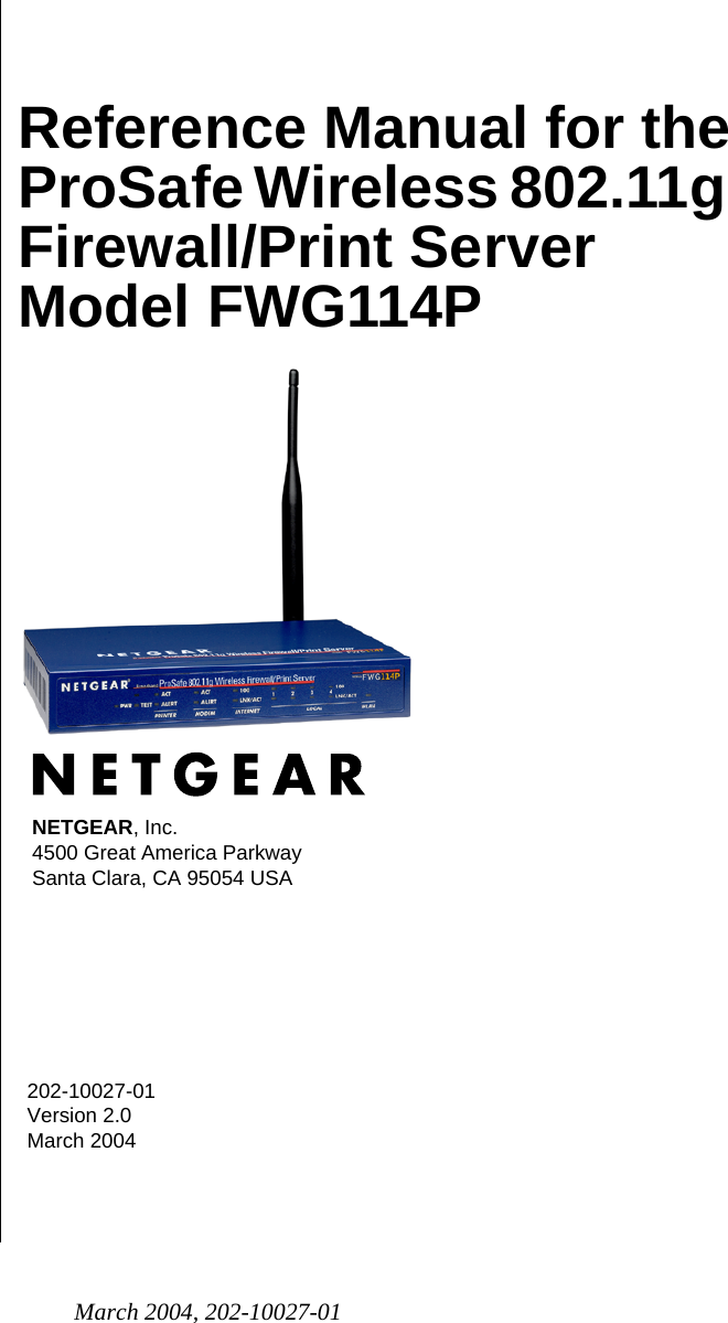
Netgear orporated FWG114PV2 ProSafe 802.11g Wireless Firewall/Print Server User Manual FullManual
Netgear Incorporated ProSafe 802.11g Wireless Firewall/Print Server FullManual
Contents
- 1. Users Manual Part 1
- 2. Users Manual Part 2
- 3. Users Manual Part 3
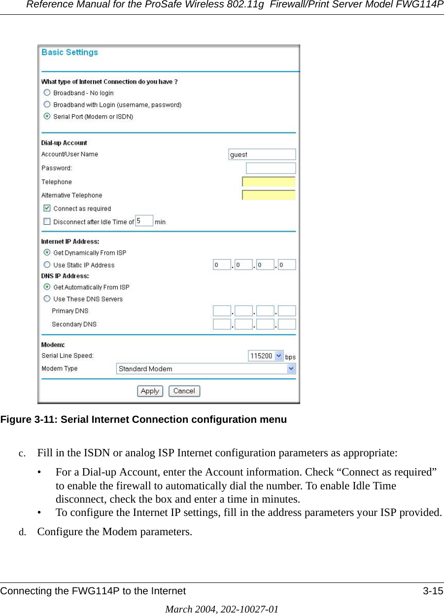
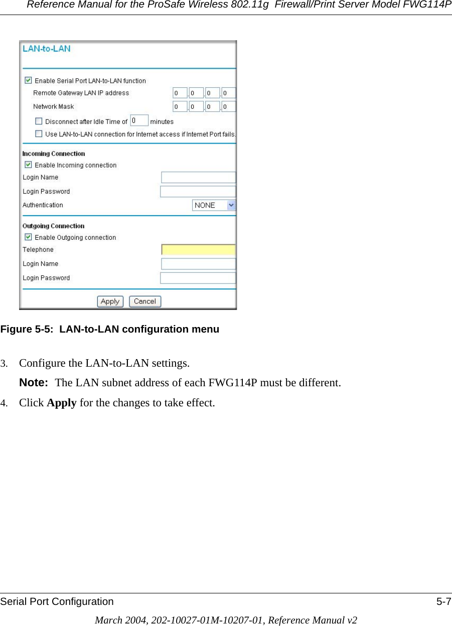
Users Manual Part 1