Netgear orporated MP115 Wireless Digital Media Player User Manual KEYAKI
Netgear Incorporated Wireless Digital Media Player KEYAKI
users manual
Page 1 of 36
2BDF0-020017 REV.00
MP115 A/V
Digital Media Player
User’s Guide

Page 2 of 36
2BDF0-020017 REV.00
Table of Contents
History of MP115 Wireless A/V Digital Media Player User’s Guide ............................. 1
1. Production Highlights ..................................................................................................... 4
MP115 Digital Media Player (NA) Appearance........................................................ 10
MP115 Digital Media Player (UK) Appearance ....................................................... 11
MP115 Digital Media Player Configuration Layout ................................................ 12
2. Setting the MP115 Digital Media Player..................................................................... 13
Before Your Begin ........................................................................................................ 13
Environmental Information........................................................................................ 13
Safety Information....................................................................................................... 13
Package Contents......................................................................................................... 13
MP115 Digital Media Player Front/Rear Panel Overviews..................................... 14
Determining the Best Possible Connections .............................................................. 15
Connecting Your TV YPbPr Video with RCA to RCA Jacks................................ 16
Connecting Your TV S-Video with S-DIN to S-DIN Jack...................................... 16
Connecting Your TV RGB Analog Video with RCA to RCA Jack....................... 17
Connecting Your TV Composite Video with SCART to SCART Jack................. 17
Connecting Your TV Audio/Video with RCA to SCART Jacks............................ 18
Connecting Your TV RGB Analog Video with RCA and Coaxial Cable via RF
Modulator.................................................................................................................... 18
Connecting a Stereo Audio Receiver (or Powered Speakers) with RCA to RCA
Jacks ............................................................................................................................ 19
Connecting Your TV Audio with RCA to RCA Jacks............................................ 19
Connecting TV and Digital Media Player Power.................................................... 20
3. Network Setup ............................................................................................................... 21
Do You have a Network............................................................................................... 21
Hub, Routers, and Switches........................................................................................ 21
Network Address: Static and Dynamic...................................................................... 21
Overview of Home Networks ...................................................................................... 21
DHCP (Dynamic Host Client Protocol) Server......................................................... 21
Router and Internet Connection Sharing.................................................................. 21
Wired Home Network.................................................................................................. 22
Preparing for Wired Setup........................................................................................ 22
Wired Home Network Connection.......................................................................... 22
Wired with Dynamic Address.................................................................................. 22
Wired with Static Address....................................................................................... 23
Wired with Crossover Cable Connection............................................................... 23
Wireless Home Network.............................................................................................. 24
Preparing for Wireless Setup .................................................................................... 24
Wireless Infrastructure............................................................................................ 25
Wireless Ad Hoc........................................................................................................ 25
Wireless Encryption................................................................................................... 26
Connecting Media Server and Network .................................................................... 26
Connection Information.............................................................................................. 26
Orientation of the Wireless Antenna........................................................................ 27

Page 3 of 36
2BDF0-020017 REV.00
Fine Tuning the Digital Media Player Antenna (Wireless) .................................... 27
Remote Control ............................................................................................................ 27
Remote Control Buttons Function............................................................................ 27
Remote Control Battery Installation........................................................................ 29
4. MP115 Digital Media Player Operation Environment Preliminary ........................ 30
Service Considerations ................................................................................................ 30
Plastic Parts................................................................................................................. 30
Cables and Connectors .............................................................................................. 30
Preventing Electrostatic Damage ............................................................................... 30
Packaging and Transporting Precautions ................................................................. 30
Workstation Precautions............................................................................................. 30
Grounding Equipment and Methods ......................................................................... 31
5. Troubleshooting Tips (A) for Hardware ..................................................................... 32
6. Glossary.......................................................................................................................... 34
7. Safety and Regulatory................................................................................................... 34

Page 4 of 36
2BDF0-020017 REV.00
MP115 Wireless Audio/Video Digital Media Player
User’s Guide
Product Highlights
This document describes in detail the specification of a Wireless Audio/Video Digital Media Player for the
MP115 designed to support UPnP compatible, and UPnP A/V conformant, networked audio/video capable of
playing streaming audio (formats are supported: MP3, WMA, MAV, and AAC), video (formats are supported
: MPEG1/2/4 and Divx4/5), and images (formats are supported: GIF, JPG, BMP, and TIFF) via a wired or
wireless home network.
The MP115 Wireless Audio/Video Digital Media Player is a consumer product that delivers high-quality
audio and video to stereos/Television (It connects to a television using either Composite Video, S-Video,
Component Video, or SCART (optionally for EU versions.) throughout the home.
Use the Digital 5’s Streaming Media Server software that provides the tools for managing your digital media.
Digital media is organized into the Media Library, which is loaded with your existing media when media
files are imported from your media file applications or your hard drive. The Streaming Media Server
software also provides the interface between your PC and the Digital Media Player. The Streaming Media
Server software must be running in order for the Digital Media Player to communicate with your PC, and
bring the media capabilities of your PC to the comfortable confines of your living room. Now, all of the
media stored in your PC can be accessed right from your entertainment center. Streaming Media is not
limited to audio, but also streams video and brings all of your digital images right to your TV screen. You
can opt for the convenience of current wireless networking standards or the security and reliability of good
old-fashioned wires.
The Streaming Media is a client-server system but not in the traditional sense. It is comprised of a client and
a server device. Media stored in the server is played from the client. The Digital Media Player has no
permanent storage thus it is called the “client” because its purpose is to browse and playback content. The
PC has permanent storage and thus it is called the “server”. Image, movie, and music files can all be “saved”
to the Digital Media Player from the PC. The communication between these devices is accomplished across
a network, which can either be wired (using the 802.3 Ethernet standard) or wireless using the 802.11b or the
802.11g standard and shall support Atheros 108Mbps throughput with the mini-PCI interface).
The MP115 Digital Media Player is sophisticated piece of electronic unit and you must choose a proper
working environment for the Digital Media Player. Avoid places that expose the components to dust, grease,
extreme temperatures, or high humidity. An environment you’d consider suitable for a stereo receiver or TV
should also serve your Digital Media Player well. Arrange the components securely on a firm, level surface,
then follow the instructions as user’s guide or relative documents.
Page 5 of 36
2BDF0-020017 REV.00
MP115 Digital Media Player (NA) Appearance
Page 6 of 36
2BDF0-020017 REV.00
MP115 Digital Media Player (UK) Appearance
Page 7 of 36
2BDF0-020017 REV.00
MP115 Digital Media Player Configuration Layout
Streaming Media Server is a client-server system that comprised of a client and a server device. The MP115
Digital Media Player has no permanent storage thus it is called the “client” because its purpose is to browse
and playback content. The PC has permanent storage and thus it is called the “server”. Images, movies, and
music files can all be served to the Digital Media Player from the PC. The communication between these
devices is accomplished across a network, which can either be wired (using the 802.3 Ethernet standard) or
wireless (using the 802.11b or the 802.11g standard).
Page 8 of 36
2BDF0-020017 REV.00
Setting the MP115 Digital Media Player
Before Your Begin
• Refer to the manual of your TV, stereo receiver, or other equipment as necessary. Note the style of jacks
and connectors on the other equipment. Determine how to choose different audio and video in channel
on your other equipment so you can see and hear the images, movies, and music on the TV, stereo, etc.
• Disconnect all equipment from the power outlets. Connect the equipment to the power outlets only after
you have finished hooking up everything. Never make or change connections with equipment connected
to the power outlet.
Environmental Information
The MP115 Digital Media Player has materials that can be recycled and reused if disassembled by a
specialized company. Please observe the local regulations regarding the disposal of packing materials, and
old equipment.
Safety Information
• Do not expose the MP115 Digital Media Player to excessive moisture, rain, sand, heat, or humidity.
• Place the MP115 Digital Media Player on a firm, flat surface.
• Keep the MP115 Digital Media Player away from domestic heating equipment and direct sunlight.
• When placing the MP115 Digital Media Player in a cabinet, allow enough space all around the Digital
Media Player for ventilation and antenna orientation. Leave enough room in front of the Digital Media
Player for the remote sensor control.
• When the MP115 Digital Media Player is turned off, it is still consuming some power. To disconnect the
Digital Media Player from the power supply completely, remove the AC power plug from the power
outlet.
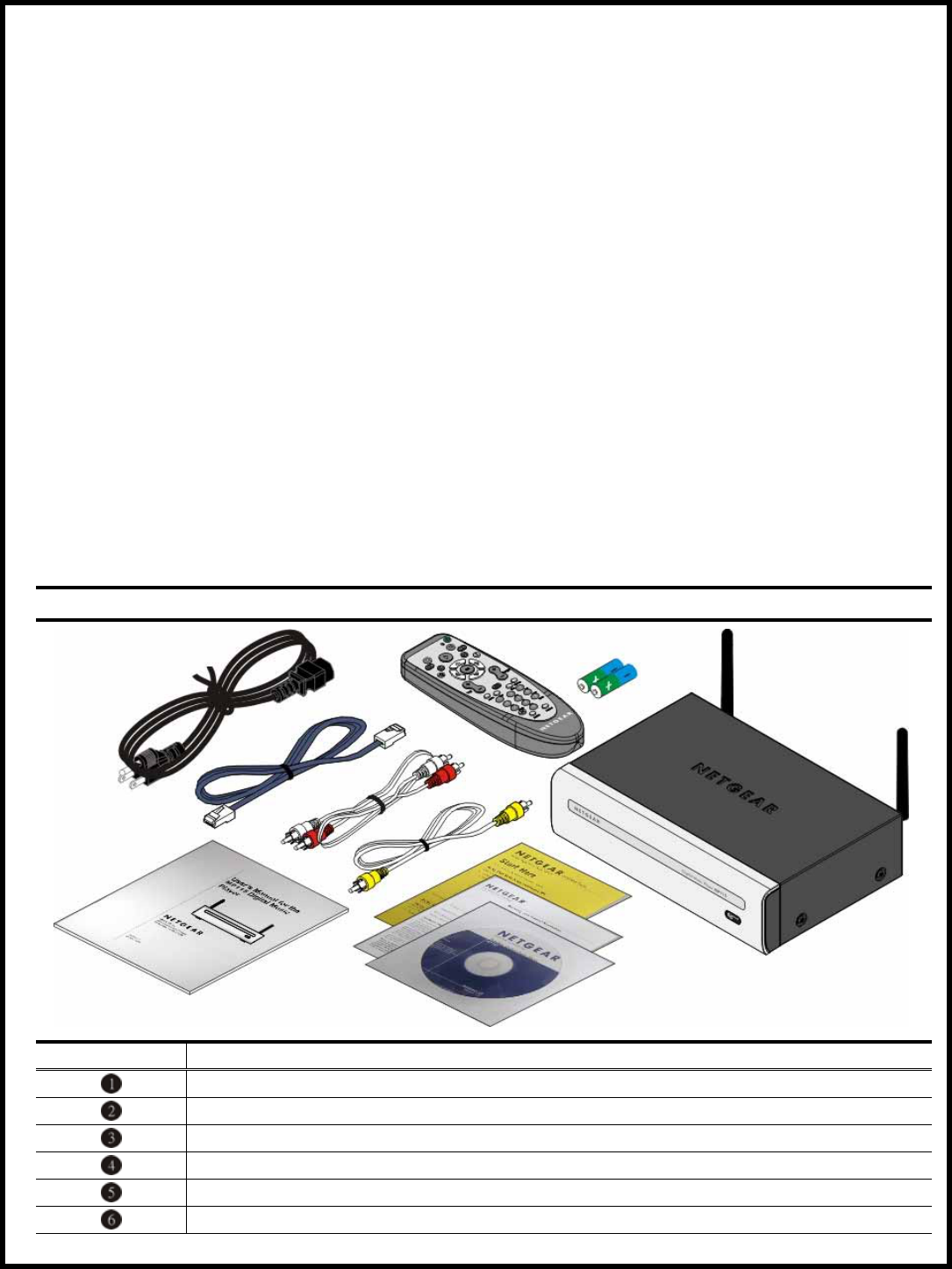
Package Contents
Make sure you have the items are included with MP115 Digital Media Player. Note that some cables may
be packed inside the egg box that holds the adapter-examine the box carefully before discarding it.
MP115 Digital Media Player Contents
Item Content Descriptions
MP115 Wireless Audio/Video Digital Media Player
Remote Control + Batteries (R6/AA-1.5V)
Ethernet Cable (CAT.5 UTP)
RCA Stereo Audio Cable (red and white colored)
RCA Analog Video Cable (yellow colored)
AC Power Code
Page 9 of 36
2BDF0-020017 REV.00
Resource CD
Installation Guide
Warranty/Support Information Card
User’s Manual
MP115 Digital Media Player Front/Rear Panel Overviews
Before you continue, please take a moment to become familiar with the locating and purpose of controls,
the status panel, connectors, and ports, which are illustrated in the following:
MP115 Digital Media Player Front/Rear Panel Overviews
Appearance Definition Functional Descriptions
Infrared (IR) Sensor
Opening
The infrared (IR) sensor receives commands from
remote control. The IR sensor is located on lower-right
corner of the front of Digital Media Player.
Dual Wireless (802.11g/b)
Antenna
The wireless antenna can rotate on connector (
perpendicular to the antenna base). You may want to
try several different angles -90 to +90 degrees for the
best reception. Minimum requirements of 802.11g/b
must be met.
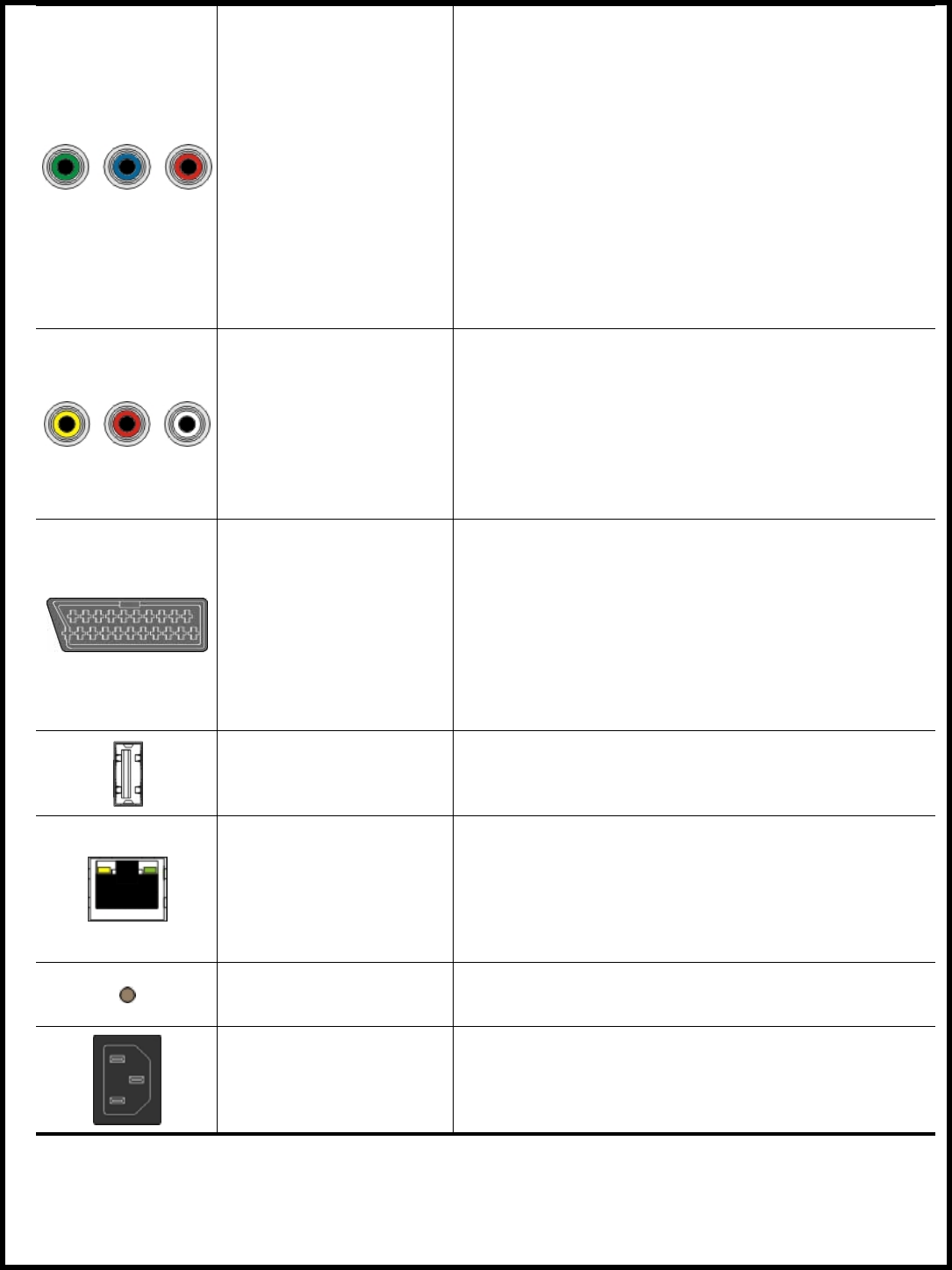
S-Video Out Jack
Separate video, also called Y/C video. Separate luma (
Y) and chroma (C) video signals are used, rather than
a single composite video signal. By simply adding
together the Y and C signals, you generate a composite
video signal. The IEC 60933-5 standard specifies the
S-Video connector, including signal levels.
Connect an S-Video cable (not supplied) to the S-Video
jack on the Digital Media Player. Connect the other
ends of the S-Video cable to the S-Video jack on the
TV.
Page 10 of 36
2BDF0-020017 REV.00
YPbPr Video Out
Jacks
YPbPr is a scaled version of the YUV (YUV is the
color space used by the NTSC and PAL video system.)
color space, with specific levels and timing signals,
designed to interface equipment together. For HDTV
interfaces, 0.3V tri-level sync signals are used, while
for SDTV interface, a 0.3V bi-level sync signal is
present. Most use the YPbPr notation rather than
Y’PbPr or Y’Pb’Pr’. The technically correct notation is
Y’Pb’Pr’ since all three components are derived from
R’G’B’.
Connect the YPbPr Video cable (which has red/green/
blue marking and that not supplied) to the YPbPr Video
jack on the Digital Media Player. Connect the other
ends of the YPbPr Video cable to the YPbPr Video jack
on the TV. Match the cable colors to the jack colors.
Analog Audio/RCB
Video Out Jacks
Connect the supplied Video cable (which has yellow
markings) to Composite Video jack on the Digital
Media Player. Connect the other ends of the Video
cable to the Video In jack on the TV.
Connect the supplied Audio cable (which has red and
white markings) to the Audio Out L/R jacks on the
Digital Media Player. Connect the other ends of the
Audio cable to the Audio In jacks on the TV. Match the
cable colors to the jack colors.
SCART Video Out
Jack
This is a 21-pin connector supported by many
consumer video components in Europe. It allows mono
or stereo audio, and composite, S-Video, or RGB Video
to be transmitted between equipment.
The IEC 60933-1 and 60933-2 standards specify the
basic SCART connector, including signal levels.
Connect an SCART Video cable (not supplied) to the
SCART jack on the Digital Media Player. Connect the
other end of the SCART Video cable to the SCART
jack on the TV.
USB Port Jack
USB 1.1 host port. The port will be used for USB disk
drives and/or memory cards.
Ethernet Port Jack
Use the supplied Ethernet cable to connect the LAN
RJ45 jack to a 10BASE-T/100BASE-TX Ethernet
network hub or route. The Digital Media Player will
also work in 10/100Mbps Ethernet.
Two Ethernet LEDs on the rear Ethernet Port jack.
►Link (Amber is 10Mbps and Green is 100Mbps)
►Activity (Green flashing)
Reset Switch
This switch reset the Digital Media Player status that
you can push once for soft reset, or push & hold to
return unit to factory default configure.
Power AC Inlet Jack
Plug the power cord (female) to the Power AC Inlet
jack on the Digital Media Player. Plug the other end
of the power cord (male) into an active power outlet.
The Digital Media Player uses an internal power supply
unit and it can automatically detect the AC line level.
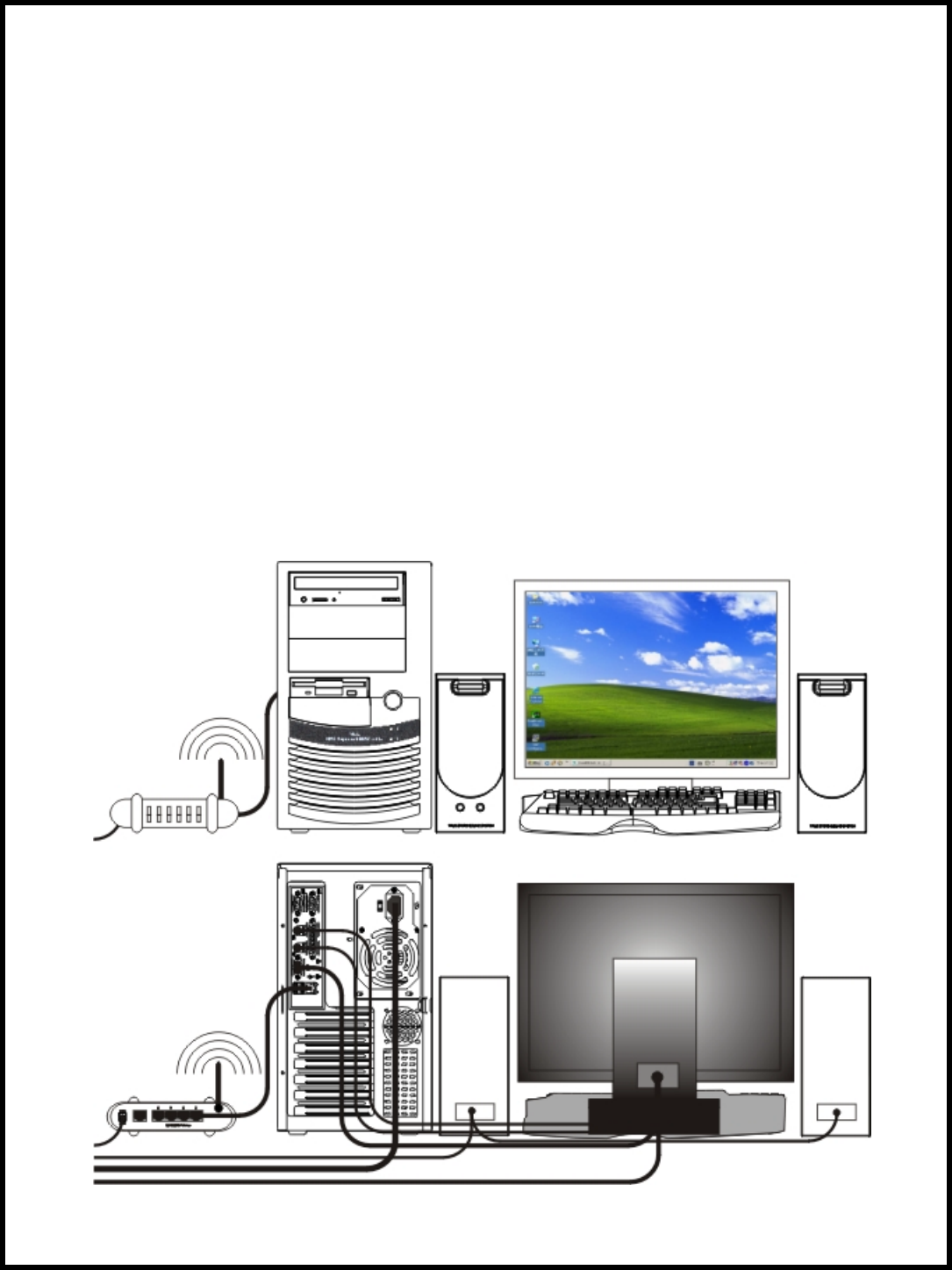
Determining the Best Possible Connections
The capabilities of your existing equipment, especially your TV, will determine your connection
possibilities. However, the following guidelines describe which options provide the best picture and sound
quality.
Page 11 of 36
2BDF0-020017 REV.00
Classification Description
Video Connection Section
OOOO YPbPr video provides the best picture quality. Details are on page 16.
OOO S-video provides excellent picture quality. Details are on page 16.
OO RGB Analog video provides good picture quality. Details are on page 17.
OO This is a 21-pin connector supported by many consumer video components in
Europe. It allows mono or stereo audio and composite, S-video, or RGB video to
be transmitted between equipment. Details are on page 17.
OO Your TV may have only an RF-style jack, usually labeled Antenna In, or 75 ohm,
or RF In. You will need an RF modulator in order to view the Digital Media Player
at your TV. Details are on page 18.
Audio Connection Section
OOO
Connect the Digital Media Player’s red and white AUDIO OUT jacks to the
AUDIO IN jacks on the TV, stereo receiver, or RF modulator. Details are on page
19.
OO Connect the Digital Media Player’s red and white AUDIO OUT jacks to the
AUDIO IN jacks on the TV. Details are on page 19.
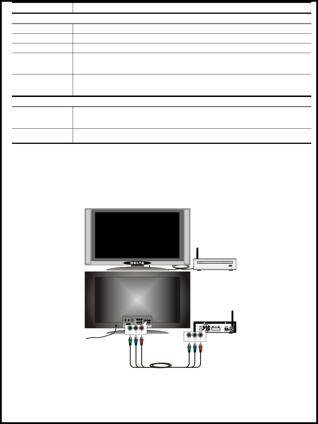
Connecting Your TV YPbPr Video with RCA to RCA Jacks
• If your TV has a YPbPr video input, you can use the YPbPr video cable (not included) with RCA line
input jacks. Refer to the connection diagram given below, then connect the YPbPr video cable (which
has red, green, blue markings) to the Digital Media Player’s Y/Pb/Pr video jacks. Connect the other
ends of the YPbPr video cable to the corresponding Y/Pb/Pr video jacks on the TV. Match the cable
colors to the jack colors.
Note: On the TV, the COMPONENT VIDEO IN jacks may be labeled YUV, YPrCr, YPbCb, or
YPbPr and may be red, green, and blue.
Connecting Your TV S-Video with S-DIN to S-DIN Jack
• If your TV has a S-video input, you can use the S-video cable (not included) with S-DN line input jack.
Refer to the connection diagram given below, then connect the S-video cable to the Digital Media
Player’s S-VIDEO jack. Connect the other end of the S-video cable to the corresponding S-VEDIO
jack on the TV.
Note: On the TV, the S-VIDEO IN jacks may be labeled Y/C, S-VIDEO, or S-VHS (Super Video).
Page 12 of 36
2BDF0-020017 REV.00
Connecting Your TV RGB Analog Video with RCA to RCA Jack
• If your TV has a RGB video input, you can use the supplied video cable with RCA line input jack (
which has yellow marking). Refer to the connection diagram given below, then connect the video cable
to the Digital Media Player’s VIDEO jack. Connect the other end of the video cable to the
corresponding VEDIO jack on the TV.
Note: On the TV, the VIDEO IN jack is usually yellow and might be labeled VIDEO, CVBS,
COMPOSITE, or BASEBAND.
Connecting Your TV Composite Video with SCART to SCART Jack
• If your TV has a SCART video input, you can use the SCART video cable (not included) with SCART
line input jack. Refer to the connection diagram given below, then connect the SCART video cable to
the Digital Media Player’s SCART video jack. Connect the other end of the SCART video cable to the
corresponding SCART video jack on the TV.
Note: The SCART video for SECAM TV in Europe only
Page 13 of 36
2BDF0-020017 REV.00
Connecting Your TV Audio/Video with RCA to SCART Jacks
• If you have a (SCART to RCA) A/V cable (not included) that one end of the A/V cable with RCA line
input jacks which has yellow, white, and red markings), and another end of the A/V cable with SCART
line input jack. Refer to the connection diagram given below, then connect the SCART line input jack
of the A/V cable to the Digital Media Player’s SCART video jack. Connect the other ends of the A/V
cable to the AUDIO L/R and VEDIO jacks on the TV. Match the cable colors to the jack colors.
Connecting Your TV Video with RCA and Coaxial Cable via RF Modulator
Before you begin, make sure you have an RF modulator and extra RF coaxial cables. These are not
supplied with Digital Media Player, but are available from most consumer electronics retailers.
• Refer to the connection diagram given below. Connect the supplied video cable (which has yellow
marking) to the Digital Media Player’s VIDEO jack. Connect the other ends of the cable to the
VIDEO jack on the RF modulator. The VIDEO jack on the RF modulator is usually yellow and might
be labeled VIDEO, CVBS, COMPOSITE, or BASEBAND.
• You probably already have an Antenna or Cable TV signal connected to the ANTENNA IN jack on
your TV. Disconnect it now from the TV. Reconnect the Antenna or Cable TV signal to the ANTENNA
Page 14 of 36
2BDF0-020017 REV.00
IN jack on your RF modulator.
• Connect an RF coaxial cable (not supplied) to the RF OUT, ANTENNA OUT, or to TV jack on the RF
modulator. The RF OUT jack may be labeled differently among different brands. Refer to the
instructions provided with your RF modulator. Connect the other ends of the same RF coaxial cable to
the ANTENNA IN or RF-IN jack on your TV.
Note: Your RF modulator should have a Channel 3/4 switch. The setting of this switch determines
the TV channel on which you will watch materials playing on the Digital Media Player. Set the RF
modulator’s Channel 3/4 switch to either 3 or 4, whichever TV channel is least used in your area. If
your RF modulator has a Modulator/Antenna switch, set it accordingly. Refer to the instructions
that came with the RF modulator. Turn on your TV and choose channel 3 or 4. Choose the same
channel to which you set the RF modulator’s Channel 3/4 switch.
Connecting a Stereo Audio Receiver (or Powered Speakers) with RCA to RCA Jacks
• Refer to the connection diagram given below. If you have a stereo receiver (or powered speakers) with
RCA analog input. Connect the supplied audio cable to the Digital Media Player’s AUDIO L/R audio
jacks. Connect the other ends of the audio cable to the AUDIO L/R audio jacks on the stereo receiver (
or powered speakers). Match the cable colors to the jack colors.
• Set the stereo receiver to the correct AUDIO IN channel or sound source. Refer to the stereo owner’s
manual for details.
Connecting Your TV Audio with RCA to RCA Jacks
• Refer to the connection diagram given below. Connect the supplied audio cable with RCA line input
jacks (which has red and white markings) to the Digital Media Player’s AUDIO L/R audio jacks.
Page 15 of 36
2BDF0-020017 REV.00
Connect the other ends of the audio cable to the AUDIO L/R audio jacks on the TV. Match the cable
colors to the jack colors.
Connecting TV and Digital Media Player Power
• Plug the power cord (female) into the power inlet jack on the Digital Media Player. Plug the other end (
male) of the power cord into an active power outlet. Also plug the power cord of the TV into an active
power outlet. Make sure that the power cords are seated properly in Digital Media Player’s receptacle
and in the AC wall outlet for TV and Digital Media Player.
Turn your Digital Media Player and TV on (change TV channels downward until you see the Digital
Media Player Setup Wizard screen saver on the TV). If you hooked up the audio to your stereo receiver,
turn your stereo receiver on as well. Tune the proper mode to match the audio connector attached to the
Digital Media Player.

Page 16 of 36
2BDF0-020017 REV.00
Network Setup
Many books have been written about the subject of networking. Therefore, this section is only intended to
provide a brief overview of how Digital Media Player works in a home network environment and covers
only those issues essential to setting up a proper network for using Digital Media Player.
Do You have a Network
If you have a single PC and you connect to the Internet with a phone line, chances are you do not have a
network. At a minimum, you will need a network interface card (NIC) for your PC, or a USB-to-802.11g/b
dongle. You can then attach the Digital Media Player to your PC. See “Wired with Crossover Cable
Connection” on page 23.
If you have a single PC and you connect to the Internet with a cable or DSL modem, check your modem
connection. If the modem has only one network jack, you still don’t have a network. You will need to
purchase a different modem or add a router to your network.
Note: You can create a network of PCs without access to the Internet. The Internet is simply a
common reason to network PCs together.
If you have multiple PCs and can share files between them, or all of the PCs can access the Internet
through a cable or DSL modem, then you do have a network. However, you will need to determine
how your server PC (the PC running the media server software) is assigned a network address.
Hubs, Routers, and Switches
When PCs are networked together, each PC is attached to a central “box” with 4, 8, 16, or more
connections. This box is either a hub, a router, or a switch. They all operate in a similar way, with one
important different: a router will assign a network address dynamically, while a hub or switch will not.
Network Address: Static or Dynamic
A PC (or any network device) is either assigned a network address manually (a static address), or another
device on the network (a DHCP server or router) assigns the address dynamically.
To determine your address settings under WindowsP
®
P XP:
• Click on Start
• Click All Programs, then Accessories, then Command Prompt
• At the prompt, type ipconfig/all
• Look for the line Dhcp Enabled (you may have to scroll back to see it)
To determine your address settings under WindowsP
®
P Me:
• Click on Start
• Click Run…
• At the prompt, type winipcfg and click OK
• Click Details… button
• Look for the line DHCP Sercer (if it has an address, DHCP is enabled)
If DHCP is enabled, you have a DHCP server on your network. See “Wired with Dynamic Address” on
page 22.
If DHCP is not enabled, you will need to assign a static address to your Digital Media Player. Take note of
the IP Address and Subnet Mask listed by the ipconfig utility, and see “Wired with Static Address” on
page 23.
Note: If you cannot tell how your network addresses are assigned, then try dynamic address (
DHCP) first. The Digital Media Player will display an error message if it is unable to dynamically
configure its address.
Overview of Home Networks
A Home Network lets you transfer files between PCs as well as share hardware and Internet connections
among several users. If you don’t have a network, you can set one up with a network starter kit, which
typically includes all of hardware and software you’ll need for a small network. Be sure to get a kit that
supports the Windows Plug and Play (PnP) standard, which makes it easier to install the driver software.
DHCP (Dynamic Host Client Protocol) Server
The easiest way for a device to get an IP address is to have it automatically assigned one by another device
, such as a PC or router, so you don’t have to do it manually. If you’re using a cable modem or DSL, cable/
DSL routers typically act as DHCP servers. You can also configure a PC as a DHCP server, as described
in
any good home networking manual.
Page 17 of 36
2BDF0-020017 REV.00
Router and Internet Connection Sharing
A “router” is a network device that forwards or “router” TCP/IP data between your network and the
Interne. Routers are typically separate boxes that connect to your network and the Internet. However,
Windows 98 S/E (and higher) provides a feature called “Internet Connection Sharing” (“ICS”) which lets
a PC connected to the Internet act as a simple router and DHCP server. On the Internet side of a router, all
of the TCP/IP data seems to be going to a single IP address, while on the network side, the router
distributes the data to each node on the network, each with a distinct IP address.
Using ICS on a PC can be a daunting task because if something goes wrong, there is litter user interface to
help you troubleshoot. Also, if the ICS PC host crashes, every PC and Digital Media Player on the
network will lose its Internet connection. Sharing a cable or DSL modem on an ICS host PC will also
required two Ethernet adapters in the PC, and figuring out which one is connected can be complicated. For
this reason , its much easier to setup a separate hardware router on your network.
Wired Home Network
In a wired home network, connect the Digital Media Player to your home network hub or router. If your
computer is connected directly to a cable or DSL modem, and there is only one network port on the back
of the modem, you do not have a home network. To set up your network, purchase a modem or router
with additional network ports. A router will allow you to share your Internet connection with other PCs,
and allows the Digital Media Player access to your music and images stored on your PC.
Preparing for Wired Setup
Ethernet requires network cable (called “CAT5”) used exclusively for transmitting the Ethernet signals
between devices. When connecting Ethernet devices together, you’ll need an Ethernet hub, or a router,
which distributes the Ethernet signal between multiple devices and controls the network traffic.
In a wired network, you attach the Digital Media Player to your network with a network cable. One end
of the cable attaches to the Digital Media Player, and the other end attaches to your PC, hub, or router.
Wired Home Network Connection
In a wired home network, all PCs are connected to a network hub or router. This may also act as a cable
/DSL modem for sharing an Internet connection.
Wired with Dynamic Address
Connect the Digital Media Player to your router, just as you would one of your computers. In almost
Page 18 of 36
2BDF0-020017 REV.00
Player network settings to wired using DHCP addressing. From the main home screen:
all cases, the router works as a DHCP server (i.e., it assigns network address). Set the Digital Media
>Press Options
>Select Network Setup
>Set Connection to Wired (Ethernet)
>Select Address
>Set Configuration to DHCP
>Press left arrow to return to Media Adapter options
>Select Apply Changes to apply the network changes
Once the Digital Media Player restarts you will be returned to the main home screen. If there are no
error messages, your network settings are properly configured.
Wired with Static Address
If a DHCP server is not available, you must assign the Digital Media Player static address that is valid
for your network. The address must be very similar to the address used by your PC, and it cannot be in
use by another network PC or device. It is best to determine the addresses of all your PCs before
assigning one to your Digital Media Player. Use the method described in item “Network Address:
Static or Dynamic” on page 21 to find the static addresses in use, and then pick an available address.
For example, you have three PCs on your network:
-PC1: 192.168.0.2; PC2: 192.168.0.17; PC3: 192.168.0.11
All with a netmask of 255.255.255.0. For the player, pick on unused address like 192.168.0.20 and
use the same netmask of 255.255.255.0. Write the address down for future reference. To configure
the Digital Media Player for the static address:
>Press Options
>Select Network Setup
>Set Connection to Wired (Ethernet)
>Select Address
>Set Configuration to Static
>Set IP Address to 192.168.0.20
>Set Netmask to 255.255.255.0
>Press left arrow to return to Media Adapter options
>Select Apply Changes to apply the network changes
The Digital Media Player will restart and if the Media Server software is running, you should see
your images, movies, and music content.
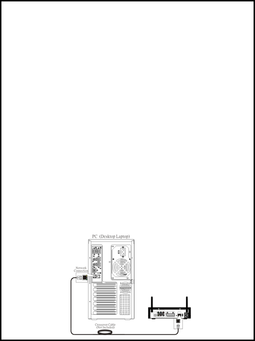
Wired with Crossover Cable Connection
If you don’t have a home network, it is still possible to access your images, movies, and music on a PC.
Connect a network crossover cable (not included) from the Digital Media Player to the network
connection on your PC. If your PC does not have a network connection, you will need to purchase a
network card.
Page 19 of 36
2BDF0-020017 REV.00
255.255.255.0 for both. To configure the Digital Media Player for a crossover cable:
Choose a static address for your PC and one for your Digital Media Player. Use a netmask of
>Press Options
>Select Network Setup
>Set Connection to Wired (Ethernet)
>Select Address
>Set Configuration to Static
>Set IP Address to 192.168.0.2
>Set Netmask to 255.255.255.0
>Press left arrow to return to Media Adapter options
>Select Apply Changes to apply the network changes
Follow the instructions that came with your network card for setting a static IP address of 192.168.0.1
on your PC.
Wireless Home Network
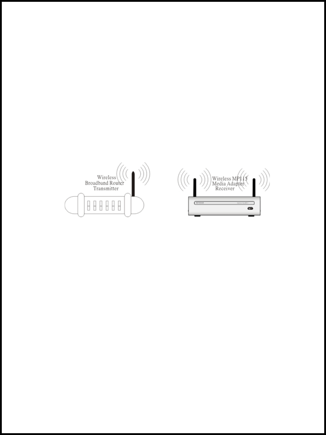
In a wireless home network, no network cable connection is required. For the best possible reception,
rotate the wireless antenna so it extends perpendicular to the Digital Media Player.
The Digital Media Player can communicate with wireless access points (infrastructure mode) or directly to
PCs with wireless network cards (ad hoc mode). Like all wireless devices, some experimentation may be
necessary to find the best location for your Digital Media Player. Signal strength and quality will depend
on distance, walls, and building structure.
Preparing for Wireless Setup
The Digital Media Player supports wireless networking. For the best results, you should setup and test
your wireless network before attempting to use the Digital Media Player wirelessly. This will rule out any
problems with your network.
• Scanning for Wireless Networks
The Digital Media Player will scan for available networks. You should know the name of your
wireless network, as the Digital Media Player may pick up other wireless networks (WLANs) in your
area. The network name is sometimes called the SSID.
Note: Your network must broadcast its name for the Digital Media Player to find it. Do not use
silent broadcast.
• Wireless Reception
Wireless reception will vary on distance, access point manufacturer, number of walls, and
environment. If possible, try setting up the Digital Media Player in an area that is close to your PC or
wireless access point. Once everything is working properly, you can experiment with placement and
distance.
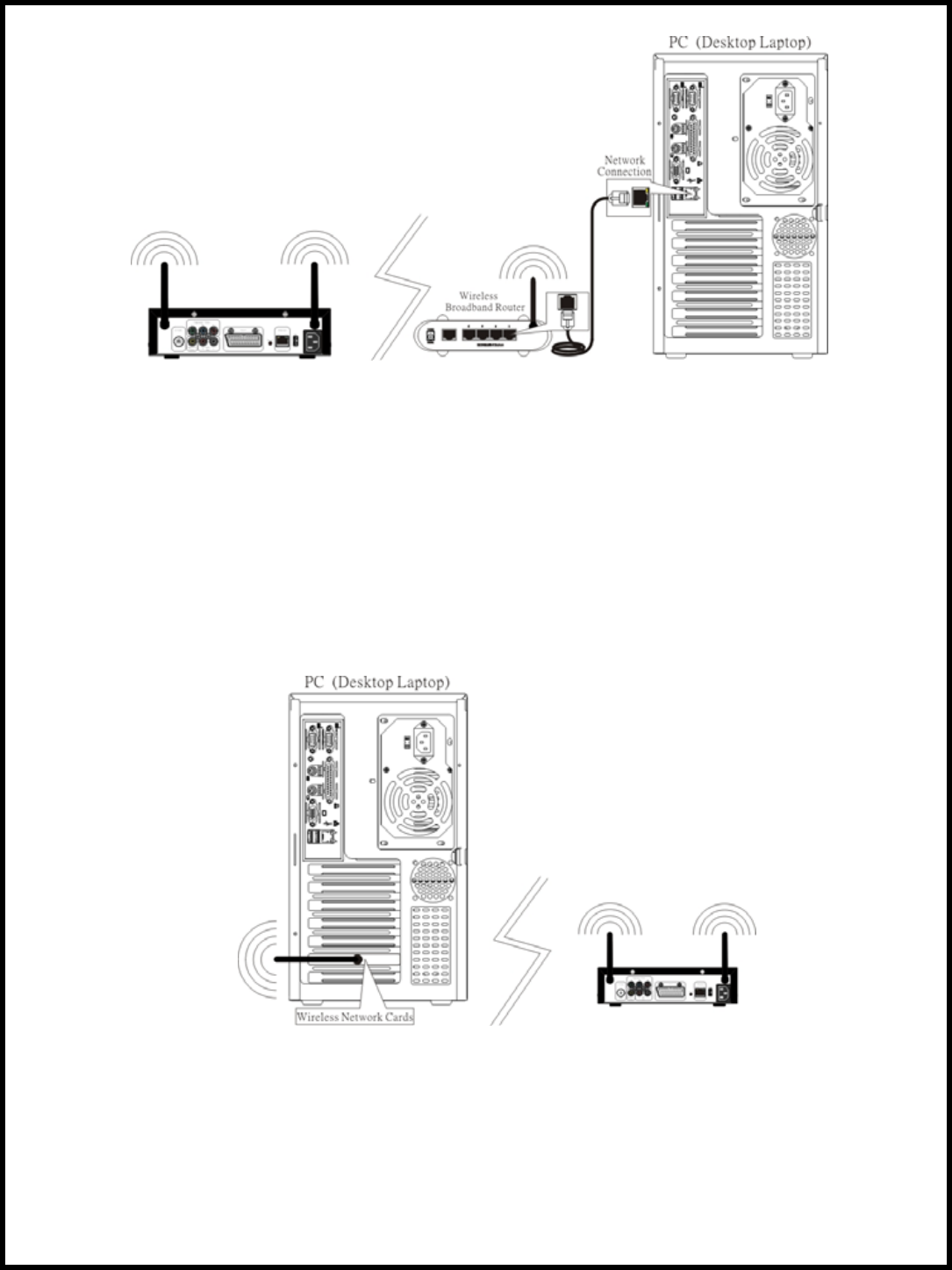
• Wireless Infrastructure or Ad Hoc
These are intimidating names for some very simple concepts.
Infrastructure mode, a wireless access point exists on the network. The access point can be in attached
to a hub or router, or the router can act as a wireless access point as well. All PCs and wireless devices
communicate through the access point.
If you do not have a wireless access point or router, you can use Ad Hoc mode. Ad Hoc mode allows
communication between a PC with a wireless card and the Digital Media Player.
Communication occurs between the devices directly without the need for an access point.
Page 20 of 36
2BDF0-020017 REV.00
Wireless Infrastructure
Most wireless networks communicate in Infrastructure mode. To configure the Digital Media Player
network settings for wireless Infrastructure and DHCP dynamic addressing:
>Press Options
>Select Network Setup
>Set Connection to Wireless (Infrastructure)
>The Digital Media Player will scan for wireless local area networks (WLAN). Select WLAN to
choose your wireless network if it is not already chosen.
>Select Address
>Set Configuration to DHCP
>Press left arrow to return to Media Adapter options
>Select Apply Changes to apply the network changes
After restarting, verify the Digital Media Player is able to play images, movies, and music.
Wireless Ad Hoc
In Ad Hoc mode, an access point does not exist and the Digital Media Player communicates directly
with computers containing wireless network cards. It is similar to a static network, without wires.
You will need to assign a static address to the Digital Media Player that is appropriate for your network.
Use method described in the item “Network Address: Static or Dynamic” on page 21 to find the static
addresses in use, and then pick an available address.
Note: If you have other wireless PCs or devices, determine all of the addresses before assigning
one to your Digital Media Player. Do not assign the same address to more than one device. For
example, you can use 192.168.0.1 for your PC, and 192.168.0.2 for your Digital Media Player.
Use a netmask of 255.255.255.0 for both.
Page 21 of 36
2BDF0-020017 REV.00
>Press Options
To configure the Digital Media Player network settings for wireless Ad Hoc mode and static addressing:
>Select Network Setup
>Set Connection to Wireless (Ad Hoc)
>Select Address
>Set Configuration to static
>Set the IP Address to 192.168.0.2
>Select Netmask to 255.255.255.0
>Press left arrow to return to Media Adapter options
>Select Apply Changes to apply the network changes
Follow the instructions that came with your wireless network card for setting a static IP address of
192.168.0.1 on your PC.
Wireless Encryption
For security reasons, a wireless network can encrypt the network packets broadcast between devices. This
type of encryption is called Wired Equivalent Privacy, or WEP.
There are two levels of WEP encryption: 64 and 128 bit. You may have heard the numbers 40 and 104 bit
used in conjunction with WEP encryption. These are just two different names for the same encryption
method. Because there has been no official standardization of these terms, wireless vendors may use either
name.
Whether you choose 64 or 128 bit is up to you. You must balance higher security versus slower network
performance.
Connecting Media Server and Network
• Plug the power cord of the PC, monitor, router, powered speakers, etc. into an active power outlet. Make
sure that the power cords are seated properly in the AC wall outlet. Turn them on.
Connection Information
This section will help you to choose a proper working environment for the Digital Media Player and its
Page 22 of 36
2BDF0-020017 REV.00
humidity. An environment you’d consider suitable for a stereo receiver and network should also serve your
peripheral. Avoid places that expose the components to dust, grease, extreme temperatures, or high
PC well. Arrange the components securely on a firm, level surface.
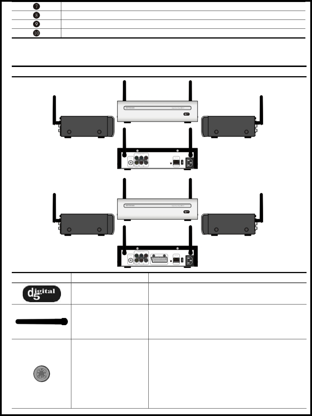
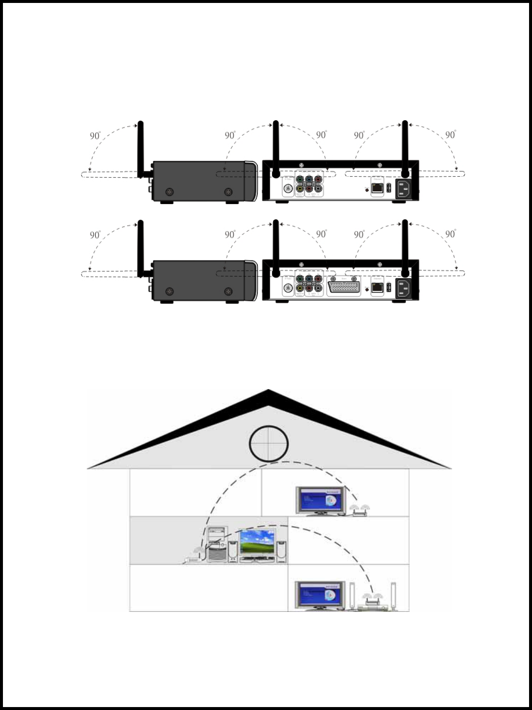
Orientation of the Wireless Antennas
Proper orientation of the wireless antenna is important for good performance. You may find that the
Digital Media Player works better with one or more of the antennas in the horizontal (flat) position. The
Digital Media Player’s receiver and transmitter tend to operate better in high locations, where the signal
path is wider and stronger. You may also need to experiment with the position of the wireless antennas on
the transmitter unit. See what position works the best for wireless antennas.
Fine Tuning the Digital Media Player Antennas (Wireless)
To get the best signal reception, the Digital Media Players should face each other using an imaginary “
line of sight”. You place the transmitter and receiver in separate rooms, or even separate floors of your
house, so you don’t have to worry about the Digital Media Players being close to each other.
Other barriers in your house may affect the signal, so you may need to adjust the positions of the
transmitter and receiver somewhat.
Remote Control
Unless stated otherwise, the remote control can operate all the features of the Digital Media Player.
Always point the remote control directly at the front of the Digital Media Player, not the TV. Point the
remote at the IR (infrared) area on the front of the Digital Media Player. Make sure there are no barriers
between the remote control and the Digital Media Player.
Remote Control Buttons Function
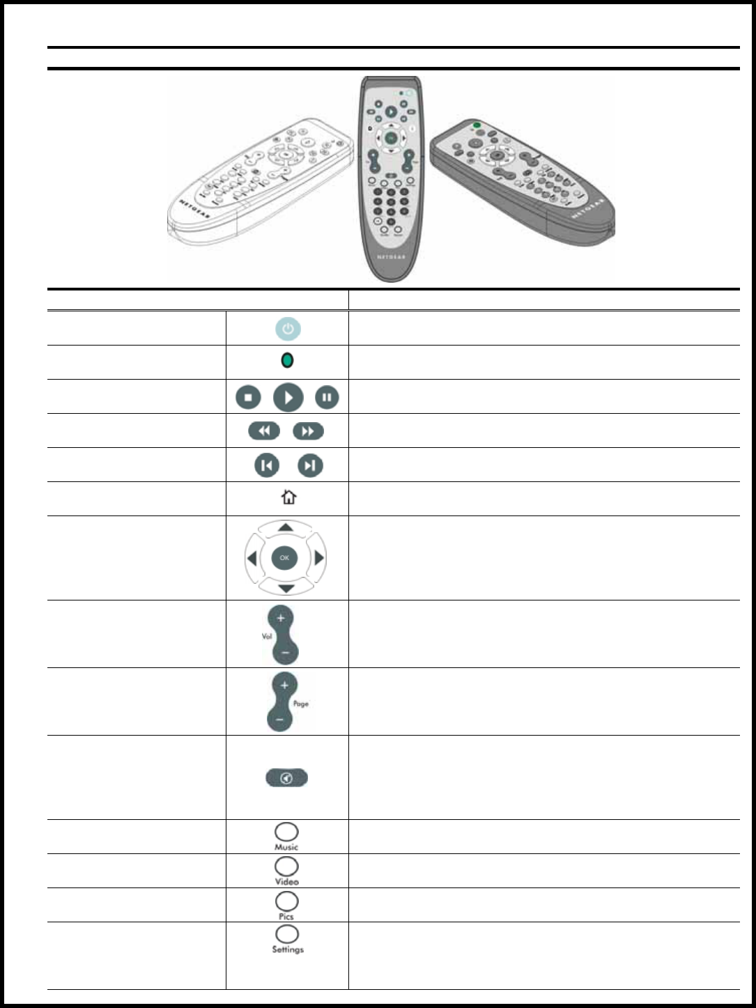
Page 23 of 36
2BDF0-020017 REV.00
You can control the Digital Media Player from the room where you are using the infrared remote control.
This section will provided a quick summary of the remote control functions.
Remote Control Buttons Function Descriptions
Buttons Function Descriptions
Power The power button turns the Digital Media Player on/off.
Light This light appears when the remote control’s button is
pressing, meaning the remote control’s power is on.
Stop, Play, Pause Stop, play, or pause music tracks or image slideshows.
Rewind, Fast forward Rewind or fast forward through a music track.
Previous, Next Skip to previous or next track, or skip images in a
slideshow.
Home Jump directly to home menu screen.
Selection arrows,
Select
Navigate the onscreen menus with the selection arrows,
and press select to choose the highlighted item.
Volume up and down
Press these buttons to control the volume.
Page up and down
Use these buttons to scroll through lists of music tracks
or images.
Mute
Press to silence or restore the volume. MUTE will
appear on the TV screen.
Press again to restore the volume (adjusting the volume
at the TV will not restore the sound). Point the remote
control at the Digital Media Player, not your TV.
Music Display the music folder option when press this button
on the home main screen.
Video Display the video folder option when press this button
on the home main screen.
Pics Display the image folder option when press this button
on the home main screen.
Settings
Display the preferences folder option when press this
button on the home main screen. You can access the
options to do the related setting for Digital Media Player
as necessary.
Page 24 of 36
2BDF0-020017 REV.00
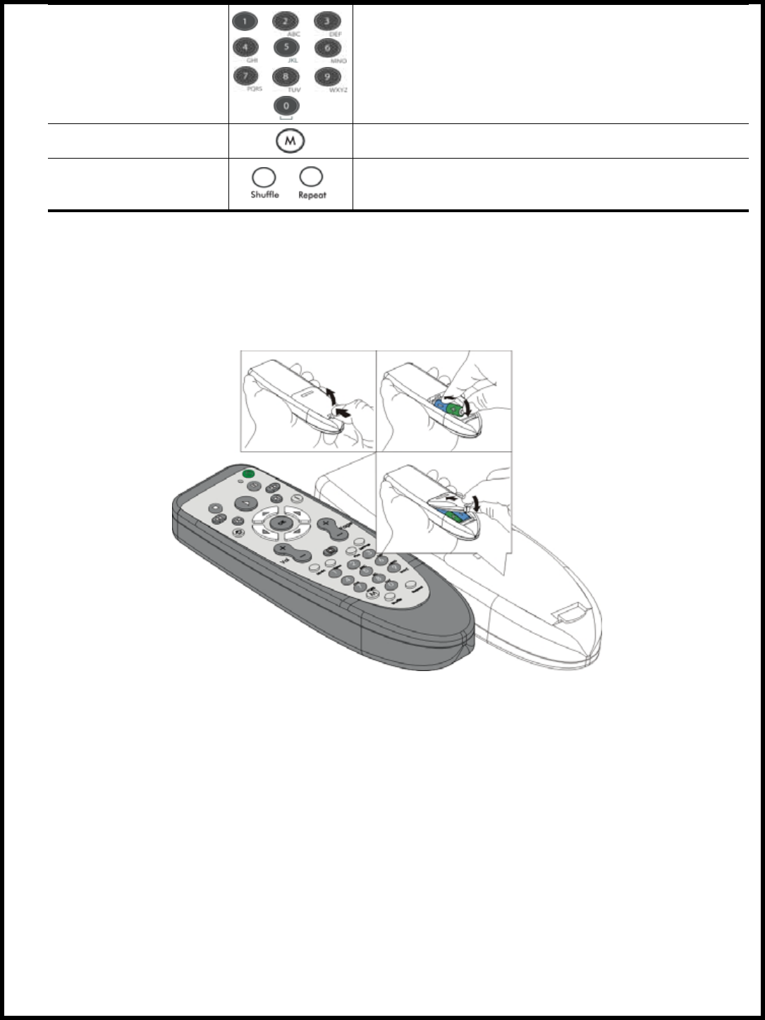
Numbers 0 ~ 9
Press to select numbered items in a menu. During
playback, press the number buttons to select a chapter (
within the current Title) or Track for playback.
M Pending.
Shuffle, Repeat Cycle between shuffle, repeat, shuffle and repeat, and
original order. Useful when playing music albums or
image slideshows.
Remote Control Battery Installation
Perform the following steps before using the remote control.
• Remove the battery compartment lid on the rear of the remote control by pressing in the tab, then
lifting off the lid.
• Place two AA batteries inside the battery compartment with their + and – ends aligned as indicated.
Do not mix old and new batteries or different types of batteries (standard, alkaline, etc.).
• Replace the battery compartment lid.

Page 25 of 36
2BDF0-020017 REV.00
MP115 Digital Media Player Operation Environment Preliminary
This section provides essential information for proper and safe installation and replacement service.
Service Considerations
The following sections include some of the considerations that you should keep in mind during disassembly
and assembly procedures.
Note: As you remove each subassembly from the Digital Media Player, place the subassembly (and
all accompanying screws) away from the work area to prevent damage.
• Plastic Parts
Using excessive force during disassembly and reassembly can damage plastic parts. Use care when
handling the plastic parts. Apply pressure only at the points designated in the maintenance instructions.
• Cables and Connectors
Cables must be handled with extreme care to avoid damage. Apply only the tension required to unseat or
seat the cables during removal and insertion. Handle cables by the connector whenever possible. In all
cases, avoid bending, twisting, or tearing cables. Ensure that cables are routed in such a way that they
cannot be caught or snagged by parts being removed or replaced. Handle flex cables with extreme care;
these cables tear easily.
Caution: When servicing the Digital Media Player, ensure that cables are placed in their proper
locations during the reassembly process. Improper cable placement can damage the Digital Media
Player.
Preventing Electrostatic Damage
Many electronic components are sensitive to electrostatic discharge (ESD). Circuitry design and structure
determine the degree of sensitivity. Networks built into many integrated circuits provide some protection,
but in many cases the discharge contains enough power to alter device parameters or melt silicon junctions.
A sudden discharge of static electricity from a finger or other conductor can destroy static-sensitive devices
or microcircuitry. Often the spark is neither felt nor heard, but damage occurs.
An electronic device exposed to electrostatic discharge may not be affected at all and can work perfectly
throughout a normal cycle. Or the device may function normally for a while, and then degrade in the
internal layers, reducing its life expectancy.
Packaging and Transporting Precautions
Use the following grounding precautions when packaging and transporting equipment:
• To avoid hand contact, transport products in static-safe containers, such as tubes, bags, or boxes.
• Protect all electrostatic-sensitive parts and assemblies with conductive or approved containers or
packaging.
• Keep electrostatic-sensitive parts in their containers until the parts arrive at static-free workstations.
• Place items on a grounded surface before removing items from their containers.
• Always be properly grounded when touching a sensitive component or assembly.
• Store reusable electrostatic-sensitive parts from assemblies in protective packaging or nonconductive
foam.
• Use transporters and conveyors made of antistatic belts and roller bushings. Ensure that mechanized
equipment used for moving materials is wired to ground and that proper materials are selected to avoid
static charging. When grounding is not possible, use an ionizer to dissipate electric charges.
Workstation Precautions
Use the following grounding precautions at workstations:
• Cover the workstation with approved static-dissipative material.
• Use a wrist strap connected to a properly grounded work surface and use properly grounded tools and
equipment.
• Use conductive field service tools, such as cutters, screwdrivers, and vacuums.
• When using fixtures that must directly contact dissipative surfaces, only use fixtures made of static-safe
materials.
• Keep the work area free of nonconductive materials, such as ordinary plastic assembly aids and
Styrofoam.
• Handle electrostatic-sensitive components, parts, and assemblies by the case or PCM laminate. Handle
these items only at static-free workstations.
• Avoid contact with pins, leads, or circuitry.
Page 26 of 36
2BDF0-020017 REV.00
Grounding Equipment and Methods
• Turn off power and input signals before inserting or removing connectors, or test equipment.
Grounding equipment must include either a wrist strap or a foot strap at a grounded workstation.
• When seated, wear a wrist strap connected to a grounded system. Wrist straps are flexible straps with a
minimum of 1 megohm ± 10% resistance in the ground cords. To provide proper ground, wear a strap
snugly against the skin at all times. On grounded mats with banana-plug connectors, connect a wrist
strap with alligator clips.
• When standing, use foot straps and a grounded floor mat. Foot straps (heel, toe, or boot straps) can be
used at standing workstations and are compatible with most types of shoes or boots. On conductive
floors or dissipative floor mats, use foot straps on both feet with a minimum of 1 megohm resistance
between the operator and ground. To be effective, the conductive strips must be worn in contact with the
skin.
Other grounding equipment recommended for use in preventing electrostatic damage includes:
• Antistatic tape
• Antistatic smocks, aprons, and sleeve protectors
• Conductive bins and other assembly or soldering aids
• Nonconductive foam
• Conductive tabletop workstations with ground cords of 1 megohm resistance
• Static-dissipative tables or floor mats with hard ties to the ground
• Field service kits
• Static awareness labels
• Material-handling packages
• Nonconductive plastic bags, tubes, or boxes
• Metal tote boxes
• Electrostatic voltage levels and protective materials
Table below shows how humidity affects the electrostatic voltage levels generated by different activities:
Typical Electrostatic Voltage Levels
Relative Humidity
Event 10% 40% 55%
Walking across carpet 35,000 V 15,000 V 7,500 V
Walking across vinyl floor 12,000 V 5,000 V 3,000 V
Motions of bench worker 6,000 V 800 V 400 V
Removing DIPS from plastic tube 2,000 V 700 V 400 V
Removing DIPS from vinyl tray 11,500 V 4,000 V 2,000 V
Removing DIPS from Styrofoam 14,500 V 5,000 V 3,500 V
Removing bubble pack from PWB 26,500 V 20,000V 7,000 V
Packing PWBs in foam-lined box 21,000 V 11,000 V 5,000 V
Note: A product can be degraded by as little as 700 volts
Table below lists the shielding protection provided by antistatic bags and floor mats.
Static-Shielding Materials
Material Use Voltage Protection Level
Antistatic plastic Bags 1,500 V
Carbon-loaded plastic Floor mats 7,500 V
Metallized laminate Floor mats 5,000 V

Page 27 of 36
2BDF0-020017 REV.00
If you are having problems with your product, check this list of problems and possible solutions before
Troubleshooting Tips (A) for Hardware
requesting service. You may be able to solve the problem yourself.
If you need to call a customer service representative, please know the model number and serial number of
your product before you call. This information is on the bottom of the product. Also, please take a moment
to identify the problem you are having, and be prepared to explain this to the representative. If you believe
the representative will need to help you with operations, please stay near the product. Our representatives
will be happy to assist you.
I don’t see the Main Screen when I turn on my Digital Media Player for the first time
• Make sure your TV is displaying the appropriate video source. You may need to use the Input, Source,
Select, or TV/Video button on your TV or TV remote to change video sources. If you are having trouble
changing the video source, refer to the instructions that came with your TV.
• If you did not connect the Digital Media Player directly to your TV but are instead passing the signal
through your VCR, make sure your VCR is displaying the appropriate video source. You may need to
use
the Input or Source button on your VCR or VCR’s remote control. Some VCRs only pass the signal
through when they are turned off. If you are having trouble displaying the correct video source, refer to
the instructions that came with your VCR.
• Make sure cables are connected to the IN jack on your TV or VCR, not the OUT jack.
• The cables you are using to connect your Digital Media Player to your TV or other equipment may be
damaged or defective. Try exchanging the cables connected to the Digital Media Player with other cables
that you know are working properly.
• Make sure you have firmly attached the AC power cord plug to the rear of the Digital Media Player. Also
, verify the AC power cord is plugged into a working power outlet and that the outlet is not controlled by
a light switch.
My remote control isn’t working
• Make sure the batteries are inserted correctly.
• Try removing the batteries and reinserting them without touching any buttons on the remote control.
• Inspect or replace the batteries with new ones.
• Aim the remote at IR (infrared) sensor on the front of the Digital Media Player (not the TV).
• Remove any obstacles between the Digital Media Player and remote control. Move closer to the Digital
Media Player and try the remote again.
I can’t see any of may music or images
• Make sure your PC is powered on and that it has not entered standby mode. Change your PC’s power
settings if you want your content to always be available.
• Make sure the media server software is running on your PC. Look for the media server icon in your
system tray. If necessary, start the media server software again.
• Click on the media server icon and select Setting to verify you are sharing the correct directories.
• If you are using a wireless network, try locating the Digital Media Player closer to your access point or
wireless PC.
• If you are using a wired network, verify the Digital Media Player network cable is properly attached to
your network hub or router, and that the hub or router has power.
• If you are using static network addresses, verify the network address and netmask are correct for your
network, and that the address is not already in use by another PC or device.
I can’t hear any sound when I’m playing music
• Make sure the audio cables are properly connected.
• If the audio cables are connected to your TV, the TV must be on to hear any music.
• If the audio cables are connected to your stereo receiver, make sure the stereo receiver is on and you
have the correct stereo input source selected. If you are having trouble selecting the correct audio source,
refer to the instructions that came with your stereo receiver.
• Make sure you did not connect the Digital Media Player’s COAXIAL digital audio out jack to an analog
jack on the stereo receiver. (Analog audio jacks are usually labeled as such and are usually red and white.
Coaxial jack is usually orange.)
• To perform an audio test, select the music jukebox and then press the options button. Select the audio
test option to play a brief audio test on your speakers.

Page 28 of 36
2BDF0-020017 REV.00
Some of my music files don’t appear
• The Digital Media Player supports the most common music file formats. However, there are almost an
infinite variety of bit rates and sample rates. If a file does not appear on the Digital Media Player, it most
likely uses an unsupported rate.
• The files may be copy protected. To share your files turn copy protection off when you rip them.
• The following sample rates are supported: 4, 8, 16, 22.05, 24, 32, 44.1, 48, 88.2, and 96KHz.
• For best results, rip your music files at 128Kbps or higher, with a sample rate of 44.1KHz.
To check the bit and sample rates of a music file, right click on the filename and select Properties.
Select the Summary tab and scroll to bottom of the list.
The file to the right has a bit rate of 128Kbps and a sample rate of 44KHz.
In most cases, you don’t need to worry about the sample rate unless you come across a file that will not
play appear on your Digital Media Player. Use the above procedure to check the file setting for supported
rates.
I created a playlist on my PC, but it doesn’t appear on my Digital Media Player
• Make sure the playlist file is located in a folder shared by your Digital Media Player. Copy the playlist to
your shared music folder, or click on the media server icon to add or change your folder options.
• Make sure you save the playlist in the industry standard .m3u playlist format. This is the only format
supported by your Digital Music Player. Load your playlist into your music software and select Save As
…’ then choose the .m3u format.
My Digital Media Player can’t find my access point
• Verify that your access point is not broadcasting silently.
• Try moving the Digital Music Player closer to your access point.
• Check your WEP setting. See “Wireless Encryption” on page 20.
My Digital Media Player finds my access point, but won’t connect
• Most likely your WEP settings are incorrect. See “Wireless Encryption” on page 20.
• Try resetting and power on the access point.
How do I reset my Digital Media Player?
• Under normal circumstances, you should not need to reset your Digital Media Player. However, to fully
reset the Digital Media Player, disconnect the AC power cord from the rear. Wait a few seconds, then
plug the AC power cord in.
• Or, you can push the reset switch on the rear of the Digital Media Player. Push the once for soft reset, or
push & hold to return the Digital Media Player to factory default configure.
What version of Firmware do I have?
• From the Main Menu screen, press the Setting button on the remote control and select Maintenance
option. The firmware version will be listed.

Page 29 of 36
2BDF0-020017 REV.00
Glossary
10BaseT/100BaseTX: These are Ethernet standard, which operated at 10Mbps/100Mpbs (megabits per
second). Also known as simply Ethernet.
802.11: Standard specifying the characteristics for wireless local area networks.
Access Point: An internetworking device that seamlessly connects wired and wires networks together.
Ad Hoc: One of two types of wireless networking, usually used for smaller networks. PCs communicate
directly with each other without an access point.
Album: An album of music released by an artist, or a group of images stored in a folder on a hard drive.
BMP: A MicrosoftP
™
P WindowsP
®
P standard for storing bitmapped images.
AUDIO OUT jacks: Jacks on the rear of the Digital Media Player that send audio to another equipment (
TV, stereo receiver, etc.).
Color system: There are various systems for transmitting television signals, for example PAL, SECAM,
and NTSC. NTSC is the most common color system in the United States of America.
Component Video YPbPr jacks: The Video Out jacks on the rear of the Digital Media Player that send
high-quality video to a TV that has Component Video In jacks. The jacks on the Digital Media Player are
red, blue, and green.
Cable Modem: A class of modem that is used for connecting to a cable TV network, which offers
Internet service.
Category 5: A type of cabling used by Ethernet networks. Category 5 cable is rated for 100Mbps.
Crossover Cable: Most network cables are straight-through cables. A crossover cable has the send and
receive connections swapped, which is useful when connecting two network devices together without a hub
, router, or switch.
DHCP: Dynamic Host Configuration Protocol. Some music files have security built in so they cannot be
copied.
DSL Modem: A class of modem used for connecting a digital subscriber line.
Digital: Sound that has been converted into numerical values. Digital sound is available when you use the
Digital Media Player’s SPDIF COAXIAL and SPDIF OPTICAL jacks, which sends audio through multiple
channels instead of two channels as analog does.
Dolby® Digital: A surround sound system that provides 5.1 channel sound as used in movie theaters.
Ethernet: A popular network technology for connecting PCs and other devices. Also called 10BaseT/
100BaseTX.
Folder: Another name for a subdirectory on a PC. A folder contains other files, such as music or images.
Genre: A type of music, such as rock, country, or classical. There are many music genres.
GIF: Graphical Interchange Format. A popular format for storing images.
Hub: A device that interconnects PC and network devices, sometimes amplifying the signals between them.
Icon: A small graphical picture.
ID3 Tag: A tagging system that allows the storage of music information such as artist, song title, and album
title within the music file.
Infrastructure: One of two types of modes used for wireless networking. PCs and devices communicate
through a common access point. Access points transmit data to PCs equipped with wireless network
adapters, which can roam within a certain range of the access point.
IP Address: Internet Protocol address, sometimes referred to as a network address. This is a series of
twelve numbers that uniquely identifies a client on the network. For example, 192.168.0.1.
Jack: A jack is a socket for attaching the cables.
JPEG: JPEG stands for Joint Photographic Experts Group. However, what people usually mean when they
use the “JPEG” is the image compression standard they developed. JPEG was developed to compress still
images, such as photographs, a single video frame, something scanned into the PC, and so forth. You can
run JPEG at any speed that the application requires. For a still picture database, the algorithm doesn’t have
to be very fast. If you run JPEG fast enough, you can compress motion video-which means that JPEG
would have to run at 50 or 60 fields per second. This is called motion JPEG or M-JPEG. You might want to
do this if you were designing a video editing system. Now, M-JPEG running at 60 fields per second is not
as efficient as MPEG 2 running at 60 fields per second because MPEG was designed to take advantage of
certain aspects of motion video.
LAN: Local Area Network. A small network that typically spans a single building or campus.

Page 30 of 36
2BDF0-020017 REV.00
Luma: As mentioned in the definition of chroma, the NTSC and PAL video systems use a signal that has
two pieces: the black and white part, and the color part. The black and white part is the luma. It was the
luma component that allowed color TV broadcasts to be received by black and white TVs and still remain
viewable.
Mbps: Abberviation for megabits per second.
Modulator: A modulator is basically a circuit that combines two different signals in such a way that they
can be pulled apart later. What does this have to do with video? Let’s take the NTSC system as an example,
although the example applies equally as well to PAL. The NTSC system may use the YIQ or YUV color
space, with the I and Q or U and V signals containing all of the color information for the picture. Two
3.58MHz color subcarriers (90 degrees out of phase) are modulated by the I and Q, or U and V components
and added together to create the chroma part of the NTSC video.
MP3: An MPEG audio file. This is a very popular format for storing digital music.
MPEG: MPEG stands for Moving Picture Experts Group. This is an ISO/IEC (International Standards
Organization) body that is developing various compression algorithms. MPEG differs from JPEG in that
MPEG takes advantage of the redundancy on a frame-to-frame basis of a motion video sequence, whereas
JPEG does not.
MPEG1: MPEG1 was the first MPEG standard defining the compression format for real-time audio and
video. The video resolution is typically 352x240 or 352x288, although higher resolutions are supported.
The maximum bit rate is about 1.5Mbps. MPEG1 is used for the Video CD format.
MPEG2: MPEG2 extends the MPEG1 standard to cover a wider range of applications. Higher video
resolutions are supported to allow for HDTV applications, and both progressive and interlaced video are
supported. MPEG2 is used for the DVD-Video and SVCD formats, and also forms the basis for digital
SDTV and HDTV.
MPEG4: MPEG4 uses an object-based approach, where scenes are modeled as compositions of objects,
both natural and synthetic, with which the user may interact. Visual objects in a scene are described
mathematically and given a position in a two- or three-dimensional space. Similarly, audio objects are
placed in a sound place. Thus, the video or audio object need only be defined once; the viewer can change
his viewing position, and the calculations to update the audio and video are done locally.
Classical “rectangular” video, as from a camera, is one of the visual objects defined in the standard. In
addition, there is the ability to map images onto computer-generated shapes, and a text-to-speech interface.
Network: A collection of PCs, printers, and devices that are connected together in order to share resources.
Network Cable: A cable similar to a telephone line, except large. A telephone cable typically has four
wires
, and a network cable has eight. Also called an RJ45 cable.
NIC: Network Interface Card. Also called a network adapter, a NIC is a device that connects a PC to a
network. Usually this is a card that installs in the PC.
PC: A personal computer.
Playlist: A file containing a list of music files used to play tracks in a particular order. The most common
playlist format is m3u.
PNG: Portable Network Graphics. A popular graphics file format for storing images.
Ripping: A slang term for converting a music CD into compressed music files. Music tracks are ripped
from the CD, compressed, and stored digitally on a hard drive.
RGB: Red-Green-Blue. A top-quality video connection where red, green, and blue components of the
picture are carried through separate wires. This also is referred to as the component video connection.
Router: A device similar to a hub. A router moves data between different network segments, and allow all
users in a network to share a single connection to the Internet.
SCART jack: A SECAM video system. This is another color video format similar to PAL. The major
differences between the two are that in SECAM the chroma is FM modulated and the R-Y and B-Y signals
are transmitted line sequentially. SECAM stands for Sequentiel Couleur Avec Memoire or Sequential Color
with Memory.
Server: A PC or software program that provides services to clients. In this document, the term server refer
to the media software running on a PC.
SNR: Signal-to-noise ratio is the magnitude of the signal divided by the amount of unwanted stuff that is
interfering with the signal (the noise). SNR is usually described in decibels, or “dB” for short; the bigger

Page 31 of 36
2BDF0-020017 REV.00
the number, the better looking the picture.
SSID: Service Set Identifier. A network ID unique to a network. Only clients and Access Points that share
the same SSID are able to communicate with each other. This string is case-sensitive.
SPDIF COAXIAL jack: Sends digital audio to a stereo receiver, allowing you to adjust the volume at
stereo receiver. The stereo receiver must have a Coaxial In jack. This connection provides the 5.1 channel
surround sound as heard in movie theaters. The SPDIF COAXIAL jack on the Digital Media Player is
orange.
Note: SPDIF short for Sony/Philips Digital InterFace. This is a consumer interface used on transfer
digital audio. A serial, self-clocking scheme is used, base on a coax or fiber interconnect.
The audio samples may be 16-24 bits each. 16 different sampling rates are supported, with 32, 44.1,
and 48KHz being the most common. IEC 60958 now fully defines this interface for consumer and
professional applications.
SPDIF OPTICAL jack: Sends digital audio to a stereo receiver, allowing you to adjust the volume at
stereo receiver. The stereo receiver must have an Optical In jack. This connection provides the 5.1 channel
surround sound as heard in movie theaters. The SPDIF OPTICAL jack on the Digital Media Player is gray.
Static Address: A network address that does not change and usually assigned manually.
S-Video: Produces a clear picture by sending separate for the luminance and the color. Separate video, also
called Y/C video. Separate luma (Y) and chroma (C) video signals are used, rather than a single composite
video signal. By simply adding together the Y and C signals, you generate a composite video signal. The
IEC 60933-5 standard specifies the S-Video connector, including signal levels.
Switch: A devices similar to a hub, but smarter. It improves network performance by reducing competition
for bandwidth.
System Tray: The Windows system tray, usually located in the lower-right corner of the display.
VIDEO OUT (Composite Video) jack: Yellow jack on the rear of the Digital Media Player that sends
video to a TV.
WEP: Wired Equivalent Privacy. A method of encryption designed to give wireless networks the same
security found on wired networks.
Wi-Fi: Wireless Fidelity. Another term for wireless networking using the 802.11 standard.
WLAN: Wireless Local Area Network. A wireless LAN does not use cable to transmit signals, but rather
uses radio to transmit packets through the air.
WMA: Windows Media Audio file. A popular format for storing audio files, created by MicrosoftP
™
P and
used by Windows Media Player.
YIQ: YIQ is a color space optionally used by the NTSC video system. The Y component is the black-and-
white portion of the image. The I and Q parts are the color difference components; these are effectively
nothing more than color placed over the black and white, or luma, component. Many people use the YIQ
notation rather than Y’IQ or Y’I’Q’. The technically correct notation is Y’I’Q’ since all three components
are derived from R’G’B’.
YPbPr: YPbPr is scaled version of the YUV color space, with specific levels and timing signals, designed
to interface equipment together. For HDTV interfaces, a 0.3V tri-level sync signals are used, while for
SDTV interfaces, a 0.3V bi-level sync signal is present. Most use the YPbPr notation rather than Y’PbPr or
Y’Pb’Pr’. The technically correct notation is Y’Pb’Pr’ since all three components are derived from R’G’B’.
YUV: YUV is the color space USED BY THE NTSC and PAL video systems. As with the YIQ color space,
the Y is the luma component while the U and V are the color difference components. Many people use the
YUV notation when they actually mean YCbCr data. Most use the YUV notation rather than Y’UV or
Y’U’V’. The technically correct notation is Y’U’V’ since all three components are derived from R’G’B’.
YUV is also the name for some component analog interface on consumer equipment. Some manufacturers
incorrectly label YCbCr. THX certification requires it to be labeled YPbPr.
Page 32 of 36
2BDF0-020017 REV.00
This section defines the general requirements for physical, electrical, mechanical, safety, and EMC of
Specifications and Regulatory
MP115 by client and DELTA/DHBU. These requirements help to ensure that items shipped to client are
received in satisfactory condition. The related notices are as following:
Item Description
Features
Product Name MP115 Wireless Audio/Video Digital Media Player
Versions Needed NA (North America), UK (United Kingdom)
Hardware
Case Metal with plastic front bezel
External Dimensions 240(L) x 186(W) x 127.5(H) mm
Weight
Power Supply
Uses an internal power supply. 100~240V/50~60Hz/~0.35A
input localized plug throughout the world, and automatically
detect the AC line level. +12V/–1.25A/15W (max.) output to
main board
Power Cable
1.8m 3-prong electrical plug with safety rating of 18
AWG/3C
black power cable, or the power cable will change to localize
throughout the world
Standby Mode Instant on/off
Memory (Flash/RAM/DRAM) 4MB Flash (upgradeable firmware)/8MB SDRAM/32MB
DRAM
CPU AliP
®
P T6306 Media Adapter Multimedia Processor
MAC Address Range NETGEAR specified
10/100Mbps Ethernet Port
1 RJ-45 Ethernet port (IEEE 802.3i/3u), connect to an
Ethernet 10BASE-T/100BASE-TX network, Port loopback,
Link integrity, Auto-detect port speed; Link/Activity LEDs in
jack
Ethernet Port LEDs Link/Activity for Ethernet in RJ-45 jack
Uplink Button or Auto-MDIX Auto-MDI/MDIX, Auto uplink
Ethernet Cable CAT5 Ethernet cable (10ft.) that colored BLUE
Wireless (Atheros mini-PCI wireless
card)
• IEEE 802.11g/b wireless LAN interface operating in the
2.4GHz ISM Band and support Atheros 108Mbps
throughput
• Supports 802.11g/b infrastructure and peer-to-peer (Ad-
Hoc) mode
• Supports Wired Equivalent Privacy (WEP) with 64/128-bit
key, WPA, and AES
• Supports DHCP or static IP addressing
• RF transceiver for 802.11 g/b
Wireless Channels By region, country code limit channel selection (NA: 1~11,
Europe: 1~13, Japan: 1~14)
Antenna
• External antenna gain (max.: ≥2dBi, average: ≥ 1.5dBi)
• Internal antenna gain (max.: ≥1dBi, average: ≥0dBi)
• Rotation on connector (perpendicular to the antenna base (
-90 to +90 degrees)
• Bandwidth: 2400~2484MHz, at return loss ≤-10dB
• External/Internal RF power handling: 200mW
Peak Antenna Gain >2dBi, when antenna integrated to the unit

Page 33 of 36
2BDF0-020017 REV.00
Average Antenna Gain >0dBi, when antenna integrated to the unit
Antenna Yield >50%, when antenna integrated to the unit
Antenna Diversity Want
Typical Transmit Power 17dBm at 8% PER, at the antenna port with 802.11g/b data
transmission
Minimum Transmit Power 14dBm at 8% PER, at the antenna port with 802.11g/b data
transmission
Receiver Sensitivity at 11Mbps ≤82dBm at 8% PER, at the antenna port
Receiver Sensitivity at 1Mbps
≤90dBm at 8% PER, at the antenna port
Maximum Receive Signal >+10dBm at 8% PER, at the antenna port
Current Consumption at Power Save Mode <80mA
Audio Out Must, RCA (L, R) stereo; Fixed output
Dolby Digital 5.1
Audio Maximum Output 1.8Vpp@30mA max load, 1Vrms, 24-bit, 96KHz DAC
Signal-to-Noise 85dB
THD+N -78dB, A weighted
Crosstalk -66dB@1KHz
Frequency Response 20Hz~20KHz ±1dB
DAC Resolution 16 bits
Video Out Composite Video RCA (Yellow)
S-Video Out S-Video S mini-DIN (4-pin female)
YPbPr Video Out Component Video RCAx3 (Red/Green/Blue)
SCART Video Out Composite Video SCART (21-pin male)
Video Output Signals
S-Video Cable
Stuffing option, 1.5m S-Video cable (DIN 4-pin female-to-
DIN 4-pin female that plug its cable connector into the DIN
jack marked “S-Video” on the rear panel of Digital Media
Player
RCA Video Cable
1.5m video cable (RCA-to-RCA that the RCA connector
colored Yellow)
• The cable connector colored Yellow must be connected to
the RCA jack marked with the letter “Composite Video” on
the rear panel of Digital Media Player
RCA Audio Cable
1.5m audio cable (RCA-to-RCAx2 that the RCA connectors
colored red/white, 2 wires)
• The connector colored Red must be connected to the RCA
jack marked with the letter “Audio Out/R” on the rear
panel of Digital Media Player
• The connector colored White must be connected to the
RCA jack marked with the letter “Audio Out/L” on the
rear panel of Digital Media Player
Reset Switch • Push once: soft reset
• Push & hold: returns unit to factory default configure
USB Port Single USB 1.1 host port that will used as Manufactory Tool.

Page 34 of 36
2BDF0-020017 REV.00
IR Remote Receiver Must, good axis and range
IR Remote Provided by Philips (RC6 codes)
Leakage Current <0.7mA@240VAC, <0.25mA@100VAC
Operating Temperature 0~40ºC
Operating Humidity 10~90% RH
Storage Temperature
-20~70ºC
Storage Humidity
5~95% RH
Software
Software Version
UPnP AV Content Discovery (CDS) and Control Point
DHCP Client/Server Client
Network Protocols Must, ARP, IP, ICMP, TCP, UDP, RTP/RTSP
Client OS Support
Windows 98/Me/2000/XP (Minimum Pentium
500MHz processor, 128MB memory, and 20MB free disk
space on at least one PC); Want: MacOS 8+iTunes, Linux
Web Server Support S
ettings and configuration (Browsers: IE5P
+
P, Netscape
4.7P
+
P)
Audio Files Support AAC, WAV, WMA, MP3
MP3 Bitrates 16~320Kbps, 44.1, 32, 22.05, 16, 11.025, 8KHz
WMA Bitrates 32~192Kbps, 44.1, 32, 22.05KHz
Playlist Files PLS, M3U, WPL, ASX
File Tags ID3 1.1, 2.3P
+
P
Internet Radio
• MP3 (Shoutcast, Icecast, Live365)
• WMA (Windows Media, Yahoo Launch)
• Real (Real MusicPass)
Music Services Rhapsody, (Yahoo Pressplay, Real MusicPass,
MusicMatch)
Picture Files Support JPEG, GIF, BMP, TIFF
Video Files Support MPEG-1 (1.41Mbps, 352x240, 30fps; MPEG-2 up to 8Mbps,
720x480, 30fps); MPEG-4, DivX
Open API Want (For plug-ins)
Presets Want (0~9, Playlist and Internet radio, etc.)
Minimum Tracks Want (30,000)
Maximum Users 3
Wireless Users 3
Typical Users 1
Multiple Server Support Up to 5 (Content servers)
Multiple Unit Support Up to 5 (Simultaneous operation of 5 networked music
adapters on network)
Certifications-Safety
US: UL 60950
Must (Test report, Product label, Certification; may release
products earlier in different countries as certifications become
available, NETGEAR ID is 85TK)
Canada: C UL Must (Test report, Product label, Certification)
Europe: CE Mark LVD Must (Test report, Product label, Certification)

Page 35 of 36
2BDF0-020017 REV.00
Certifications-EMI
US: FCC Part 15 Class B Must (Test report, Product label, Certification)
Canada: ICES-003 Must (Product label)
Europe: CE Must (Test report, Product label, Declaration of conformity (
CISPR 22))
Certifications-Wireless
US: FCC Part 15C Must (Test report, Product label, Certification, NETGEAR ID
is PY3-MR814)
Canada: RSS-139-1 & RSS-210 Must (Test report, Product label, Certification, NETGEAR ID
is 4054-MR814)
Europe: CE R & TTE
Must (Test report, Product label, Certification (Austria,
France, Germany, Italy, Ireland, Netherlands, Norway, Spain,
Swiss, Sweden, UK, NETGEAR ID is 0560xxxx))
Hereby, NETGEAR, declares that this device is in compliance with the essential
requirements and other relevant provisions of the R&TTE Directive 1999/5/EC.
This device will be sold in the following EEA countries: Belgium Denmark Germany
Greece Spain France Ireland Italy Luxemburg Netherlands Austria Portugal Finland
Sweden United Kingdom Switzerland Norway Iceland Cyprus Czech Republic
Estonia Hungary Latvia Lithuania Malta Slovakia Poland Slovenia
FEDERAL COMMUNICATIONS COMMISSION
This device complies with Part 15 of the FCC Rules. Operation is subject to the
following two conditions:(1) this device may not cause harmful interference, and (2)
this device must accept any interference received, including interference that may
cause undesired operation.
NOTE
This equipment has been tested and found to comply with the limits for a Class B
digital device, pursuant to Part 15 of the FCC Rules. These limits are designed to
provide reasonable protection against harmful interference in a residential installation.
This equipment generates, uses and can radiated radio frequency energy and, if not
installed and used in accordance with the instructions, may cause harmful interference
to radio communications. However, there is no guarantee that interference will not
occur in a particular installation If this equipment does cause harmful interference to
radio or television reception, which can be determined by turning the equipment off
and on, the user is encouraged to try to correct the interference by one or more of the
following measures:
-Reorient or relocate the receiving antenna.
-Increase the separation between the equipment and receiver.
-Connect the equipment into an outlet on a circuit different from that to which the
receiver is connected.
-Consult the dealer or an experienced radio/TV technician for help.
Changes or modifications not expressly approved by the party responsible for
compliance could void the user‘s authority to operate the equipment.
This device and its antenna(s) must not be co-located or operating in conjunction with
any other antenna or transmitter.
The antenna(s) used for this transmitter must be installed to provide a separation
distance of at least 20 cm from all persons and must not be co-located or operating in
conjunction with any other antenna or transmitter.