Netgear orporated MR814V3 Wireless Router User Manual FullManual
Netgear Incorporated Wireless Router FullManual
Contents
- 1. Users Manual Part 1 Revised
- 2. Users Manual Part 2 Revised
Users Manual Part 1 Revised

202-10039-01
202-10039-01
Version 1.0
June 2004
NETGEAR, Inc.
4500 Great America Parkway
Santa Clara, CA 95054 USA
Reference Manual for the
MR814 v3 Cable/DSL
Wireless Router
DECLARATION OF CON”FORMITY
Per FCC Part 15 Section 15.19(a) (3)
Responsible Party Name: Netgear Incorporation
Address: 4500 Great America Parkway, Santa Clara, California 95054
USA
Phone/Fax No: +1-408-907-8000 / +1-408-907-8097
Hereby declares that the product
Product Name: Wireless Router
Model Number: MR814v3
© 2004 by NETGEAR, Inc. All rights reserved. June 2004.
Trademarks
NETGEAR is a trademark of Netgear, Inc.
Microsoft, Windows, and Windows NT are registered trademarks of Microsoft Corporation.
Other brand and product names are registered trademarks or trademarks of their respective holders.
Statement of Conditions
In the interest of improving internal design, operational function, and/or reliability, NETGEAR reserves the right to
make changes to the products described in this document without notice.
NETGEAR does not assume any liability that may occur due to the use or application of the product(s) or circuit
layout(s) described herein.
Federal Communications Commission (FCC) Compliance Notice: Radio Frequency Notice
This equipment has been tested and found to comply with the limits for a Class B digital device, pursuant to
part 15 of the FCC Rules. These limits are designed to provide reasonable protection against harmful interference in a
residential installation. This equipment generates, uses, and can radiate radio frequency energy and, if not installed and
used in accordance with the instructions, may cause harmful interference to radio communications. However, there is no
guarantee that interference will not occur in a particular installation. If this equipment does cause harmful interference to
radio or television reception, which can be determined by turning the equipment off and on, the user is encouraged to try
to correct the interference by one or more of the following measures:
• Reorient or relocate the receiving antenna.
• Increase the separation between the equipment and receiver.
• Connect the equipment into an outlet on a circuit different from that to which the receiver is connected.
• Consult the dealer or an experienced radio/TV technician for help.
EN 55 022 Declaration of Conformance
This is to certify that the MR814 v3 Cable/DSL Wireless Router is shielded against the generation of radio interference
in accordance with the application of Council Directive 89/336/EEC, Article 4a. Conformity is declared by the
application of EN 55 022 Class B (CISPR 22).
FCC Radiation Exposure Statement
This equipment complies with FCC RF radiation exposure limits set forth for an uncontrolled
environment. This equipment should be installed and operated with a minimum distance of 20
centimeters between the radiator and your body.
This device complies with Part 15 of the FCC Rules. Operation is subject to the following two
conditions:
(1) This device may not cause harmful interference, and
(2) This device must accept any interference received, including interference that may cause
undesired operation.
This transmitter must not be co-located or operating in conjunction with any other antenna or
transmitter.

202-10039-01
iii
Bestätigung des Herstellers/Importeurs
Es wird hiermit bestätigt, daß das MR814 v3 Cable/DSL Wireless Router gemäß der im BMPT-AmtsblVfg 243/1991
und Vfg 46/1992 aufgeführten Bestimmungen entstört ist. Das vorschriftsmäßige Betreiben einiger Geräte (z.B.
Testsender) kann jedoch gewissen Beschränkungen unterliegen. Lesen Sie dazu bitte die Anmerkungen in der
Betriebsanleitung.
Das Bundesamt für Zulassungen in der Telekommunikation wurde davon unterrichtet, daß dieses Gerät auf den Markt
gebracht wurde und es ist berechtigt, die Serie auf die Erfüllung der Vorschriften hin zu überprüfen.
Certificate of the Manufacturer/Importer
It is hereby certified that the MR814 v3 Cable/DSL Wireless Router has been suppressed in accordance with the
conditions set out in the BMPT-AmtsblVfg 243/1991 and Vfg 46/1992. The operation of some equipment (for example,
test transmitters) in accordance with the regulations may, however, be subject to certain restrictions. Please refer to the
notes in the operating instructions.
Federal Office for Telecommunications Approvals has been notified of the placing of this equipment on the market
and has been granted the right to test the series for compliance with the regulations.
Voluntary Control Council for Interference (VCCI) Statement
This equipment is in the second category (information equipment to be used in a residential area or an adjacent area
thereto) and conforms to the standards set by the Voluntary Control Council for Interference by Data Processing
Equipment and Electronic Office Machines aimed at preventing radio interference in such residential areas.
When used near a radio or TV receiver, it may become the cause of radio interference.
Read instructions for correct handling.
Customer Support
Refer to the Support Information Card that shipped with your MR814 v3 Cable/DSL Wireless Router.
World Wide Web
NETGEAR maintains a World Wide Web home page that you can access at the universal resource locator (URL)
http://www.netgear.com. A direct connection to the Internet and a Web browser such as Internet Explorer
or Netscape are required.
Contents v
202-10039-01
Contents
Chapter 1
About This Manual
Audience, Scope, Conventions, and Formats ................................................................1-1
How to Use This Manual ................................................................................................1-2
How to Print this Manual .................................................................................................1-3
Chapter 2
Introduction
Key Features of the Router ............................................................................................2-1
802.11b Standards-based Wireless Networking ......................................................2-2
A Powerful, True Firewall with Content Filtering ......................................................2-2
Security ....................................................................................................................2-3
Autosensing Ethernet Connections with Auto Uplink™ ...........................................2-3
Extensive Protocol Support ......................................................................................2-3
Easy Installation and Management ..........................................................................2-4
Maintenance and Support ........................................................................................2-5
Package Contents ..........................................................................................................2-5
The Router’s Front Panel .........................................................................................2-6
The Router’s Rear Panel .........................................................................................2-7
A Road Map for ‘How to Get There From Here’ .............................................................2-7
Chapter 3
Connecting the Router to the Internet
Prepare to Install Your Router ........................................................................................3-1
First, Connect the Router to the Internet ........................................................................3-1
Now, Set Up a Computer for Wireless Connectivity .......................................................3-7
Troubleshooting Tips ......................................................................................................3-8
Overview of How to Access the Router ..........................................................................3-9
How to Log On to the Router After
Configuration Settings Have Been Applied ............................................................3-10
How to Bypass the Configuration Assistant ...........................................................3-12
202-10039-01
vi Contents
How to Manually Configure Your Internet Connection ..................................................3-13
Using the Smart Setup Wizard .....................................................................................3-15
NETGEAR product registration, support, and documentation ......................................3-16
Chapter 4
Wireless Configuration
Observe Performance, Placement, and Range Guidelines ............................................4-1
Implement Appropriate Wireless Security ......................................................................4-2
Understanding Wireless Settings ...................................................................................4-3
Default Factory Settings ...........................................................................................4-3
Basic Wireless Settings ............................................................................................4-3
Advanced Wireless Settings ....................................................................................4-6
Information to Gather Before Changing Basic Wireless Settings .............................4-7
How to Set Up and Test Basic Wireless Connectivity ..............................................4-8
How to Configure WEP ..........................................................................................4-10
How to Configure WPA-PSK Wireless Security ............................................................4-11
How to Restrict Wireless Access by MAC Address ...............................................4-12
Chapter 5
Content Filtering
Content Filtering Overview .............................................................................................5-1
Blocking Access to Internet Sites ...................................................................................5-2
Blocking Access to Internet Services .............................................................................5-3
Configuring a User Defined Service .........................................................................5-4
Configuring Services Blocking by IP Address Range ..............................................5-5
Scheduling When Blocking Will Be Enforced .................................................................5-5
Viewing Logs of Web Access or Attempted Web Access ...............................................5-6
Configuring E-Mail Alert and Web Access Log Notifications ..........................................5-7
Chapter 6
Maintenance
Viewing Router Status Information .................................................................................6-1
Viewing a List of Attached Devices .................................................................................6-5
Configuration File Management .....................................................................................6-5
Restoring and Backing Up the Configuration ...........................................................6-6
Erasing the Configuration .........................................................................................6-7
Upgrading the Router Software ......................................................................................6-7
Changing the Administrator Password ...........................................................................6-8
Contents vii
202-10039-01
Chapter 7
Advanced Configuration of the Router
Configuring for Port Forwarding to Local Servers ..........................................................7-1
Adding a Custom Service .........................................................................................7-2
Editing or Deleting a Port Forwarding Entry .............................................................7-3
Local Web and FTP Server Example .......................................................................7-3
Multiple Computers for Half Life, KALI or Quake III Example ..................................7-3
Configuring the WAN Setup Options ..............................................................................7-4
Setting Up a Default DMZ Server .............................................................................7-4
Respond to Ping on Internet WAN Port ...................................................................7-5
Setting the MTU Size ...............................................................................................7-5
Using the LAN IP Setup Options ....................................................................................7-6
Configuring LAN TCP/IP Setup Parameters ............................................................7-6
Using the Router as a DHCP server ........................................................................7-8
Using Address Reservation ......................................................................................7-8
Using a Dynamic DNS Service .......................................................................................7-9
Configuring Static Routes .............................................................................................7-10
Enabling Remote Management Access .......................................................................7-12
Using Universal Plug and Play (UPnP) ........................................................................7-13
Chapter 8
Troubleshooting
Basic Functioning ...........................................................................................................8-1
Power Light Not On ..................................................................................................8-1
Lights Never Turn Off ...............................................................................................8-2
LAN or WAN Port Lights Not On ..............................................................................8-2
Troubleshooting the Web Configuration Interface ..........................................................8-3
Troubleshooting the ISP Connection ..............................................................................8-4
Troubleshooting a TCP/IP Network Using a Ping Utility .................................................8-5
Testing the LAN Path to Your Router .......................................................................8-5
Testing the Path from Your Computer to a Remote Device .....................................8-6
Restoring the Default Configuration and Password ........................................................8-7
Problems with Date and Time .........................................................................................8-8
202-10039-01
viii Contents
Appendix A
Technical Specifications
Appendix B
Network, Routing, Firewall, and Basics
Related Publications ...................................................................................................... B-1
Basic Router Concepts .................................................................................................. B-1
What is a Router? ................................................................................................... B-1
Routing Information Protocol ................................................................................... B-2
IP Addresses and the Internet ....................................................................................... B-2
Netmask .................................................................................................................. B-4
Subnet Addressing .................................................................................................. B-4
Private IP Addresses ............................................................................................... B-7
Single IP Address Operation Using NAT ....................................................................... B-7
MAC Addresses and Address Resolution Protocol ................................................. B-8
Related Documents ................................................................................................. B-9
Domain Name Server .............................................................................................. B-9
IP Configuration by DHCP ........................................................................................... B-10
Internet Security and Firewalls .................................................................................... B-10
What is a Firewall? ................................................................................................ B-10
Stateful Packet Inspection ...............................................................................B-11
Denial of Service Attack ..................................................................................B-11
Ethernet Cabling ...........................................................................................................B-11
Category 5 Cable Quality ...................................................................................... B-12
Inside Twisted Pair Cables .................................................................................... B-13
Uplink Switches, Crossover Cables, and MDI/MDIX Switching ............................ B-14
Appendix C
Preparing Your Network
What You Need To Use a Router with a Broadband Modem ......................................... C-1
Cabling and Computer Hardware ............................................................................ C-1
Computer Network Configuration Requirements .................................................... C-1
Internet Configuration Requirements ...................................................................... C-2
Where Do I Get the Internet Configuration Parameters? ........................................ C-2
Record Your Internet Connection Information ......................................................... C-3
Preparing Your Computers for TCP/IP Networking ....................................................... C-3
Configuring Windows 95, 98, and Me for TCP/IP Networking ....................................... C-4
Contents ix
202-10039-01
Install or Verify Windows Networking Components ................................................. C-4
Enabling DHCP to Automatically Configure TCP/IP Settings in Windows 95B, 98, and Me
C-6
Selecting Windows’ Internet Access Method .......................................................... C-8
Verifying TCP/IP Properties .................................................................................... C-8
Configuring Windows NT4, 2000 or XP for IP Networking ............................................ C-9
Install or Verify Windows Networking Components ................................................. C-9
DHCP Configuration of TCP/IP in Windows XP, 2000, or NT4 ............................. C-10
DHCP Configuration of TCP/IP in Windows XP ................................................... C-10
DHCP Configuration of TCP/IP in Windows 2000 ................................................ C-12
DHCP Configuration of TCP/IP in Windows NT4 .................................................. C-15
Verifying TCP/IP Properties for Windows XP, 2000, and NT4 .............................. C-17
Configuring the Macintosh for TCP/IP Networking ...................................................... C-18
MacOS 8.6 or 9.x .................................................................................................. C-18
MacOS X ............................................................................................................... C-18
Verifying TCP/IP Properties for Macintosh Computers ......................................... C-19
Verifying the Readiness of Your Internet Account ....................................................... C-20
Are Login Protocols Used? ................................................................................... C-20
What Is Your Configuration Information? .............................................................. C-20
Obtaining ISP Configuration Information for Windows Computers ....................... C-21
Obtaining ISP Configuration Information for Macintosh Computers ..................... C-22
Restarting the Network ................................................................................................ C-23
Appendix D
Wireless Networking Basics
Wireless Networking Overview ...................................................................................... D-1
Infrastructure Mode ................................................................................................. D-1
Ad Hoc Mode (Peer-to-Peer Workgroup) ................................................................ D-2
Network Name: Extended Service Set Identification (ESSID) ................................ D-2
Wireless Channels ......................................................................................................... D-2
Authentication and WEP ................................................................................................ D-4
802.11b Authentication ............................................................................................ D-4
Open System Authentication ................................................................................... D-5
Shared Key Authentication ...................................................................................... D-5
Overview of WEP Parameters ................................................................................ D-6
Key Size .................................................................................................................. D-7
WEP Configuration Options .................................................................................... D-8
202-10039-01
xContents
WPA Wireless Security .................................................................................................. D-8
How Does WPA Compare to WEP? ........................................................................ D-9
How Does WPA Compare to IEEE 802.11i? ........................................................ D-10
What are the Key Features of WPA Security? ...................................................... D-10
WPA Authentication: Enterprise-level User
Authentication via 802.1x/EAP and RADIUS .................................................. D-12
WPA Data Encryption Key Management ........................................................ D-14
Is WPA Perfect? .................................................................................................... D-16
Product Support for WPA ...................................................................................... D-16
Supporting a Mixture of WPA and WEP Wireless Clients ............................... D-16
Changes to Wireless Access Points ............................................................... D-16
Changes to Wireless Network Adapters ......................................................... D-17
Changes to Wireless Client Programs ............................................................ D-18
Glossary
Index
About This Manual 1
202-10039-01
Chapter 1
About This Manual
This chapter describes the intended audience, scope, conventions, and formats of this manual.
Audience, Scope, Conventions, and Formats
This reference manual assumes that the reader has basic to intermediate computer and Internet
skills. However, basic computer network, Internet, firewall, and VPN technologies tutorial
information is provided in the Appendices and on the Netgear website.
This guide uses the following typographical conventions:
This guide uses the following formats to highlight special messages:
This manual is written for the MR814 v3 router according to these specifications.:
Table 1-1. Typographical Conventions
italics Emphasis, books, CDs, URL names
bold User input
SMALL CAPS Screen text, file and server names, extensions, commands, IP addresses
Note: This format is used to highlight information of importance or special interest.
Table 1-2. Manual Scope
Product Version MR814 v3 Cable/DSL Wireless Router
Manual Publication Date June 2004
Note: Product updates are available on the NETGEAR Web site at
http://kbserver.netgear.com/products/MR814v3.asp.
Reference Manual for the MR814 v3 Cable/DSL Wireless Router
2About This Manual
202-10039-01
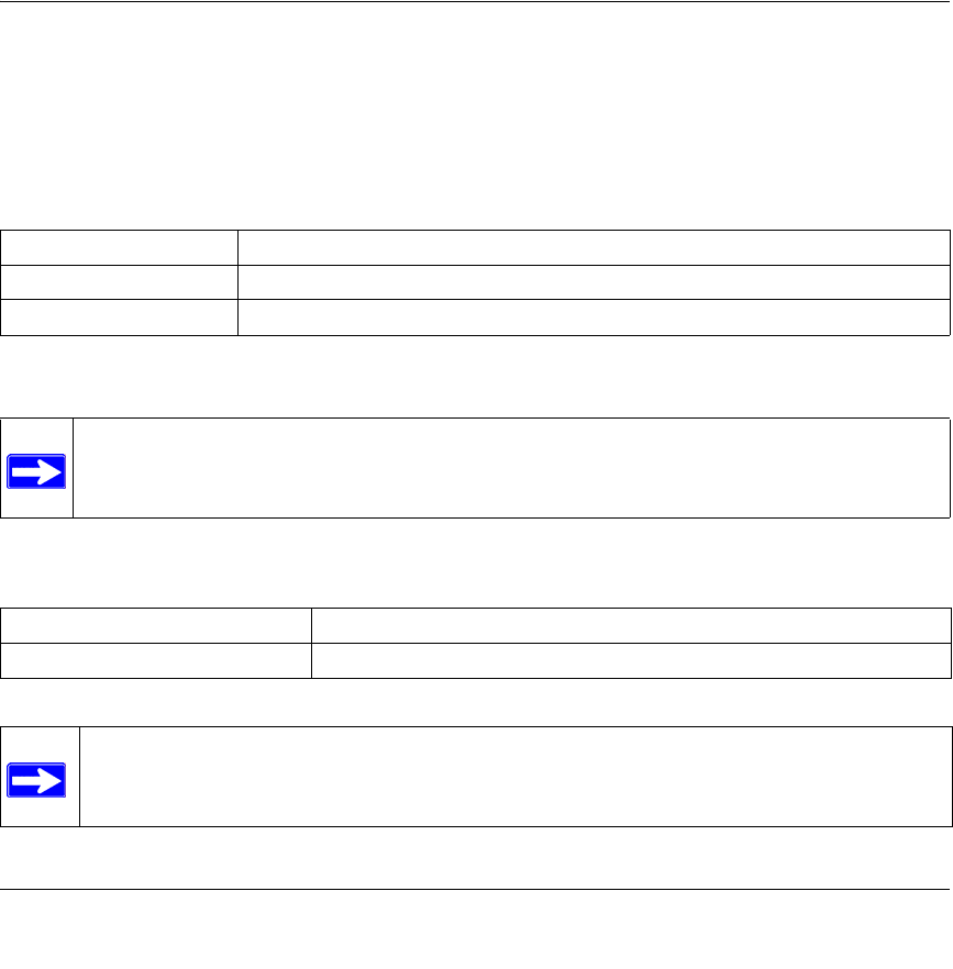
How to Use This Manual
The HTML version of this manual includes a variety of navigation features as well as links to PDF
versions of the full manual and individual chapters.
Figure 1 -1: HTML version of this manual
1. Left pane. Use the left pane to view the Contents, Index, Search, and Favorites tabs.
To view the HTML version of the manual, you must have a version 4 or later browser with
JavaScript enabled.
2. Toolbar buttons. Use the toolbar buttons across the top to navigate, print pages, and more.
The Show in Contents button locates the current topic in the Contents tab.
Previous/Next buttons display the previous or next topic.
The PDF button links to a PDF version of the full manual.
The Print button prints the current topic. Click this button when a step-by-step
procedure is displayed to send the entire procedure to your printer. You do not
have to worry about specifying the correct range of pages.
3. Right pane. Use the right pane to view the contents of the manual. Also, each page of the
manual includes a link at the top right which links to a PDF file
containing just the currently selected chapter of the manual.
12
3
Reference Manual for the MR814 v3 Cable/DSL Wireless Router
About This Manual 3
202-10039-01
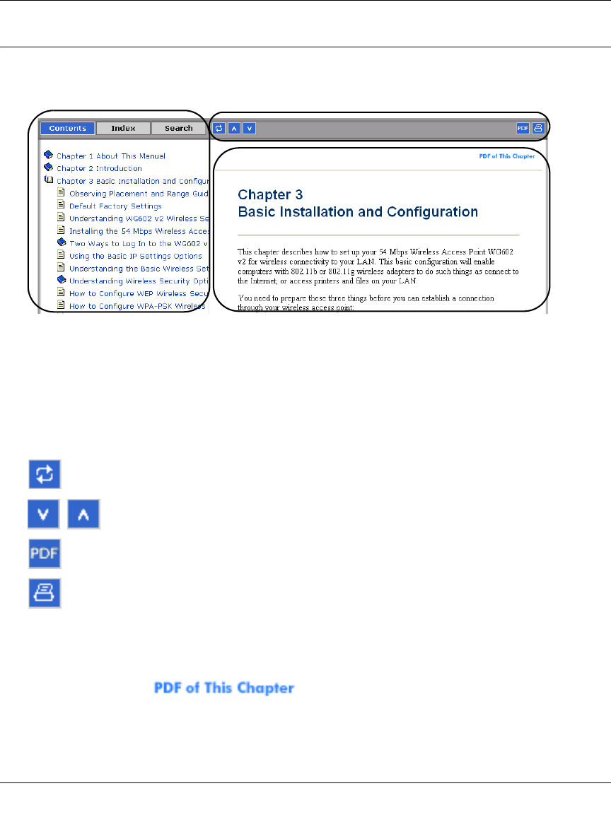
How to Print this Manual
To print this manual you can choose one of the following several options, according to your needs.
•Printing a “How To” Sequence of Steps in the HTML View.
Use the Print button on the upper right of the toolbar to print the currently displayed
topic. Use this button when a step-by-step procedure is displayed to send the entire procedure
to your printer. You do not have to worry about specifying the correct range of pages.
•Printing a Chapter.
Use the link at the top right of any page.
– Click “PDF of This Chapter” link at the top right of any page in the chapter you want to
print. The PDF version of the chapter you were viewing opens in a browser window.
Note: Your computer must have the free Adobe Acrobat reader installed in order to view
and print PDF files. The Acrobat reader is available on the Adobe web site at
http://www.adobe.com.
– Click the print icon in the upper left of the window.
Tip: If your printer supports printing two pages on a single sheet of paper, you can save
paper and printer ink by selecting this feature.
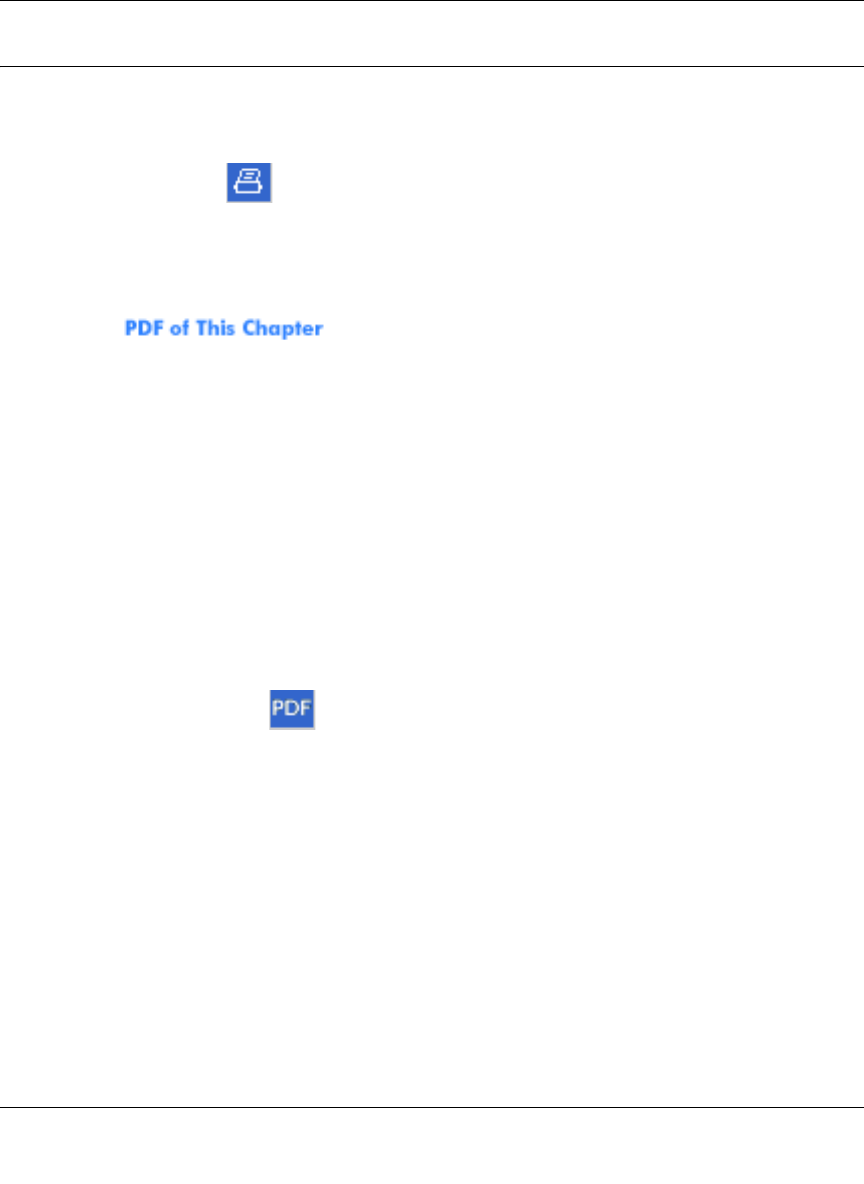
•Printing the Full Manual.
Use the PDF button in the toolbar at the top right of the browser window.
– Click the PDF button on the upper right of the toolbar. The PDF version of the
chapter you were viewing opens in a browser window.
– Click the print icon in the upper left of the window.
Tip: If your printer supports printing two pages on a single sheet of paper, you can save
paper and printer ink by selecting this feature.

Reference Manual for the MR814 v3 Cable/DSL Wireless Router
4About This Manual
202-10039-01

Introduction 2-1
202-10039-01
Chapter 2
Introduction
This chapter describes the features of the NETGEAR MR814 v3 Cable/DSL Wireless Router.
Key Features of the Router
The MR814 v3 Cable/DSL Wireless Router with 4-port switch connects your local area network
(LAN) to the Internet through an external access device such as a cable modem or DSL modem.
The MR814 v3 router provides you with multiple Web content filtering options, plus browsing
activity reporting and instant alerts -- both via e-mail. Parents and network administrators can
establish restricted access policies based on time-of-day, Web site addresses and address
keywords, and share high-speed cable/DSL Internet access for up to 253 personal computers. In
addition to the Network Address Translation (NAT) feature, the built-in firewall protects you from
hackers.
With minimum setup, you can install and use the router within minutes.
The MR814 v3 router provides the following features:
• 802.11b Standards-based wireless networking
• WPA-PSK wireless security.
• Easy, web-based Smart Wizard configuration assistant
• Content Filtering and Site Blocking Security
• Built in 4-port 10/100 Mbps Switch
• Ethernet connection to a wide area network (WAN) device, such as a cable modem or DSL
modem
• Extensive Protocol Support
• Login capability
• Front panel LEDs for easy monitoring of status and activity
• Flash memory for firmware upgrade

Reference Manual for the MR814 v3 Cable/DSL Wireless Router
2-2 Introduction
202-10039-01
802.11b Standards-based Wireless Networking
The MR814 v3 router includes an 802.11b-compliant wireless access point, providing continuous,
high-speed 11 Mbps access between your wireless and Ethernet devices. The access point
provides:
• 802.11b Standards-based wireless networking at up to 11 Mbps
• 64-bit and 128-bit WEP encryption security.
• WEP keys can be generated manually or by passphrase.
• WPA-PSK support. Support for Wi-Fi Protected Access (WPA) data encryption which
provides strong data encryption and authentication based on a pre-shared key.
• Wireless access can be restricted by MAC address.
• Wireless network name broadcast can be turned off so that only devices that have the network
name (SSID) can connect.
A Powerful, True Firewall with Content Filtering
Unlike simple Internet sharing NAT routers, the MR814 v3 is a true firewall, using stateful packet
inspection to defend against hacker attacks. Its firewall features include:
• Denial of Service (DoS) protection.
Automatically detects and thwarts DoS attacks such as Ping of Death, SYN Flood, LAND
Attack, and IP Spoofing.
• Blocks unwanted traffic from the Internet to your LAN.
• Blocks access from your LAN to Internet locations or services that you specify as off-limits.
• Logs security incidents.
The MR814 v3 will log security events such as blocked incoming traffic, port scans, attacks,
and administrator logins. You can configure the router to E-mail the log to you at specified
intervals. You can also configure the router to send immediate alert messages to your E-mail
address or E-mail pager whenever a significant event occurs.
• With its content filtering feature, the MR814 v3 prevents objectionable content from reaching
your PCs. The router allows you to control access to Internet content by screening for
keywords within Web addresses. You can configure the router to log and report attempts to
access objectionable Internet sites.

Reference Manual for the MR814 v3 Cable/DSL Wireless Router
Introduction 2-3
202-10039-01
Security
The MR814 v3 router is equipped with several features designed to maintain security, as described
in this section.
• PCs Hidden by NAT
NAT opens a temporary path to the Internet for requests originating from the local network.
Requests originating from outside the LAN are discarded, preventing users outside the LAN
from finding and directly accessing the PCs on the LAN.
• Port Forwarding with NAT
Although NAT prevents Internet locations from directly accessing the PCs on the LAN, the
router allows you to direct incoming traffic to specific PCs based on the service port number
of the incoming request, or to one designated “DMZ” host computer. You can specify
forwarding of single ports or ranges of ports.
Autosensing Ethernet Connections with Auto Uplink™
With its internal 8-port 10/100 switch, the MR814 v3 can connect to either a 10 Mbps standard
Ethernet network or a 100 Mbps Fast Ethernet network. Both the LAN and WAN interfaces are
autosensing and capable of full-duplex or half-duplex operation.
The router incorporates Auto UplinkTM technology. Each Ethernet port will automatically sense
whether the Ethernet cable plugged into the port should have a ‘normal’ connection such as to a
PC or an ‘uplink’ connection such as to a switch or hub. That port will then configure itself to the
correct configuration. This feature also eliminates the need to worry about crossover cables, as
Auto Uplink will accommodate either type of cable to make the right connection.
Extensive Protocol Support
The MR814 v3 router supports the Transmission Control Protocol/Internet Protocol (TCP/IP) and
Routing Information Protocol (RIP). For further information about TCP/IP, refer to Appendix B,
“Network, Routing, Firewall, and Basics.”
• IP Address Sharing by NAT
The MR814 v3 router allows several networked PCs to share an Internet account using only a
single IP address, which may be statically or dynamically assigned by your Internet service
provider (ISP). This technique, known as NAT, allows the use of an inexpensive single-user
ISP account.

Reference Manual for the MR814 v3 Cable/DSL Wireless Router
2-4 Introduction
202-10039-01
• Automatic Configuration of Attached PCs by DHCP
The MR814 v3 router dynamically assigns network configuration information, including
IP, gateway, and domain name server (DNS) addresses, to attached PCs on the LAN using the
Dynamic Host Configuration Protocol (DHCP). This feature greatly simplifies configuration
of PCs on your local network.
• DNS Proxy
When DHCP is enabled and no DNS addresses are specified, the router provides its own
address as a DNS server to the attached PCs. The router obtains actual DNS addresses from
the ISP during connection setup and forwards DNS requests from the LAN.
• PPP over Ethernet (PPPoE)
PPPoE is a protocol for connecting remote hosts to the Internet over a DSL connection by
simulating a dial-up connection. This feature eliminates the need to run a login program such
as Entersys or WinPOET on your PC.
Easy Installation and Management
You can install, configure, and operate the MR814 v3 Cable/DSL Wireless Router within minutes
after connecting it to the network. The following features simplify installation and management
tasks:
• Smart Wizard Configuration Assistant
A user-friendly Smart Wizard configuration assistant that automatically connects you to the
router, detects the type of Internet connection you have, and guides you through enabling your
wireless network.
• Browser-based management
Browser-based configuration allows you to easily configure your router from almost any type
of personal computer, such as Windows, Macintosh, or Linux. A user-friendly Setup Wizard is
provided and online help documentation is built into the browser-based Web Management
Interface.
• Smart Wizard
The MR814 v3 router automatically senses the type of Internet connection, asking you only
for the information required for your type of ISP account.
• Visual monitoring
The MR814 v3 router’s front panel LEDs provide an easy way to monitor its status and
activity.

Reference Manual for the MR814 v3 Cable/DSL Wireless Router
Introduction 2-5
202-10039-01
Maintenance and Support
NETGEAR offers the following features to help you maximize your use of the MR814 v3 router:
• Flash memory for firmware upgrade
• Free technical support seven days a week, twenty-four hours a day
Package Contents
The product package should contain the following items:
• MR814 v3 Cable/DSL Wireless Router.
•AC power adapter.
• Category 5 (CAT5) Ethernet cable.
•MR814 v3 Resource CD (2230-10095-01 ), including:
— This guide.
— Application Notes and other helpful information.
• Registration and Warranty Card.
• Support Information Card.
If any of the parts are incorrect, missing, or damaged, contact your NETGEAR dealer. Keep the
carton, including the original packing materials, in case you need to return the router for repair.
Reference Manual for the MR814 v3 Cable/DSL Wireless Router
2-6 Introduction
202-10039-01
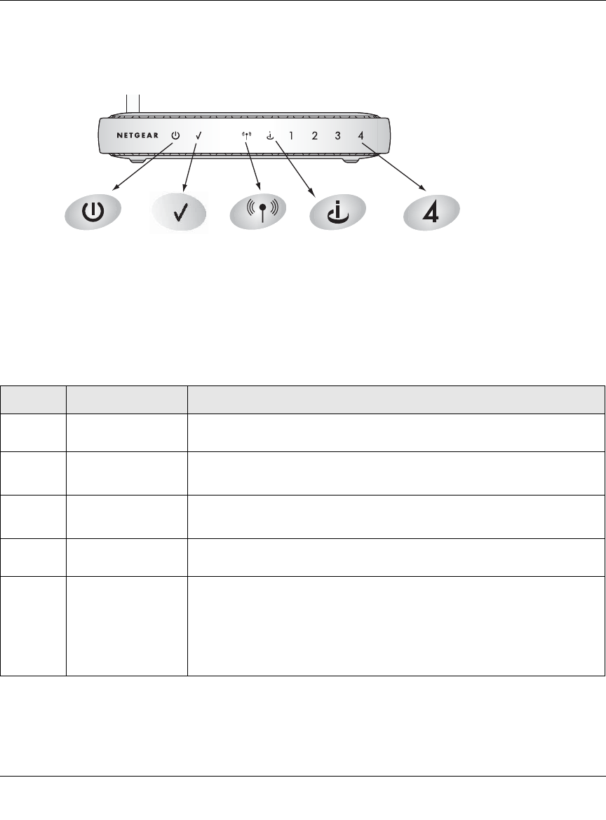
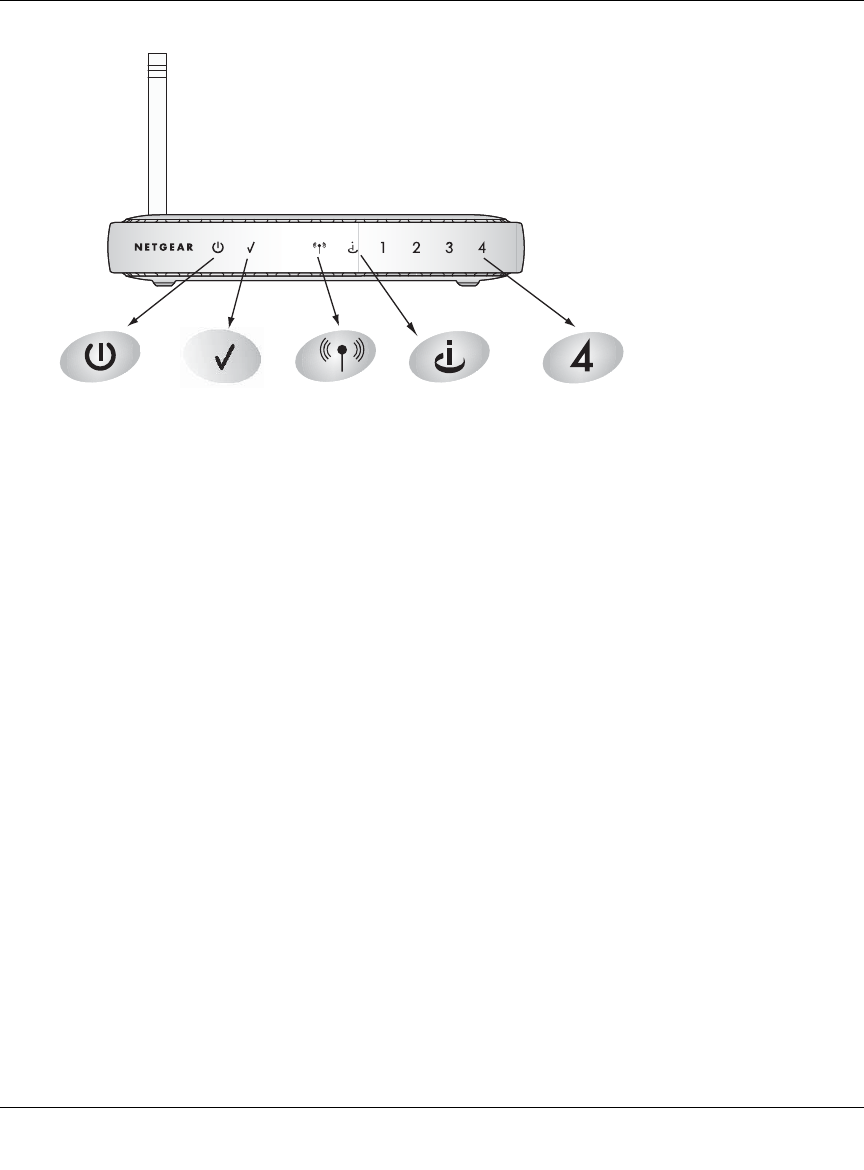
The Router’s Front Panel
The front panel of the MR814 v3 router contains the status lights described below.
Figure 2-1: MR814 v3 Front Panel
You can use the status lights to verify connections. Viewed from left to right, the table below
describes the lights on the front panel of the router.
Table 2-1. Status Light Descriptions
Label Activity Description
Power On Green Solid
Off Power is supplied to the router.
Power is not supplied to the router.
Test Blinking
Off The router is performing its diagnostic test.
The router successfully completed its diagnostic test.
Wireless On
Off The Wireless port is initialized and the wireless feature is enabled.
The wireless feature is turned off or there is a problem.
Internet On
Blink The Internet port has detected a link with an attached device.
Data is being transmitted or received by the Internet port.
LAN On (Green)
Blink (Green)
On (Yellow)
Blink (Yellow)
Off
The LAN (local area network) port has detected link with a 100 Mbps
device.
Data is being transmitted or received at 100 Mbps.
The Local port has detected link with a 10 Mbps device.
Data is being transmitted or received at 10 Mbps.
No link is detected on this port.
0OWER )NTERNET0ORT
7IRELESS ,!.0ORT
4EST
Reference Manual for the MR814 v3 Cable/DSL Wireless Router
Introduction 2-7
202-10039-01
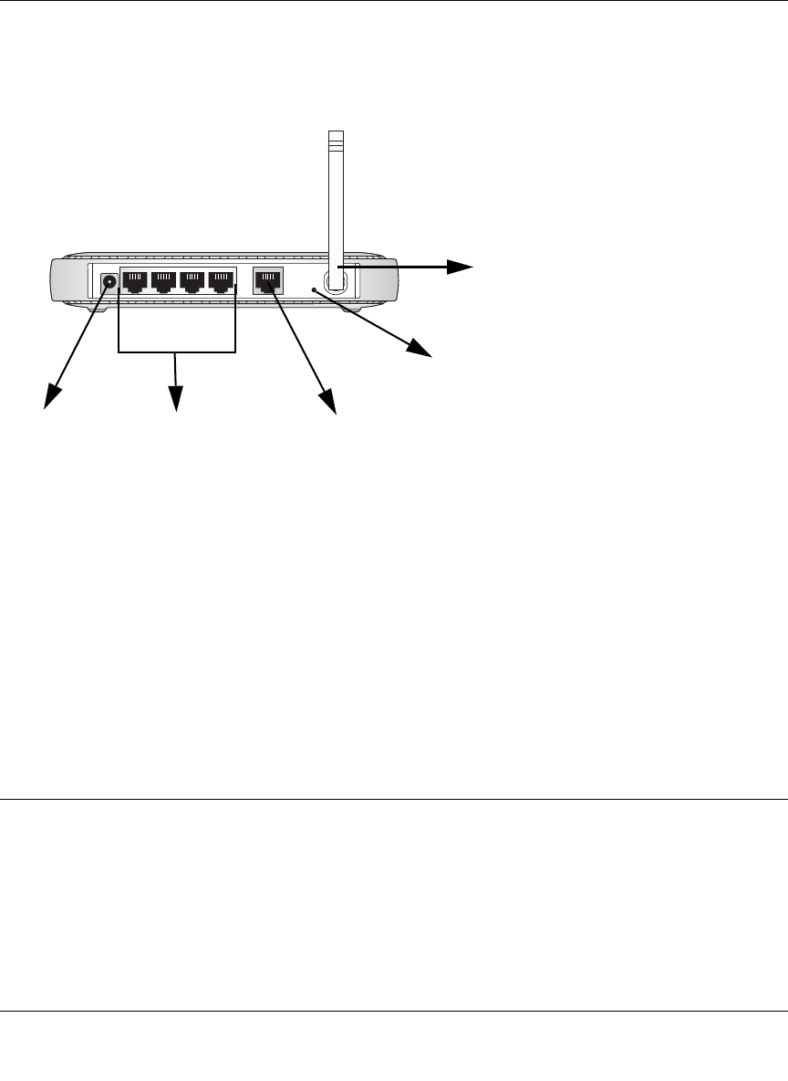
The Router’s Rear Panel
The rear panel of the MR814 v3 Cable/DSL Wireless Router contains these port connections.
Figure 1-2: MR814 v3 Rear Panel
Viewed from left to right, the rear panel contains the following features:
• AC power adapter outlet for 12 V DC @ 1 A output, 20W maximum
• Four Local (LAN) 10/100 Mbps Ethernet ports for connecting the router to the local
computers
• Internet (WAN) Ethernet port for connecting the router to a cable or DSL modem
• Factory Default Reset push button for Restoring the Default Configuration and Password
• Wireless antenna
A Road Map for ‘How to Get There From Here’
The introduction and adoption of any new technology can be a difficult process. Broadband
Internet service is considered so useful that more and more people want to set up networks in their
home to share a broadband connection. Wireless technology has removed one of the barriers to
networking—running wires. It allows more people to try networking while at the same time
exposes them to the inherent complexity of networking. General networking concepts, setup, and
maintenance can be difficult to understand. In addition, wireless technology adds issues, such as
Power 4 LAN Ports Internet Port
Reset
Wireless
4321
Antenna
Button

Reference Manual for the MR814 v3 Cable/DSL Wireless Router
2-8 Introduction
202-10039-01
range, interference, signal quality, and security to the picture.
To help overcome potential barriers to successfully using home networks, the table below
identifies how to accomplish such things as connecting to a wireless network, assuring appropriate
security measures are taken, browsing the Internet through your wireless connection, exchanging
files with other computers and using printers in the combined wireless and wired network.
Table 2-1. A Road Map for How to Get There From Here
If I Want To? What Do I Do? What’s Needed? How Do I?
Set up a
wireless
network
1. Choose a wireless
network name
(SSID) and, decide if
you need to use
wireless security,
and if so, what
settings to use.
2. Set up the MR814
v3 Cable/DSL
Wireless Router with
settings based on
step 1.
3. Set up the wireless
computers with the
settings from step 2.
• Wireless network
equipment such as the
MR814 v3 Cable/DSL
Wireless Router.
• A computer within the
operating range of the
wireless network. For
guidelines about the range
of wireless networks, see
“Observe Performance,
Placement, and Range
Guidelines”.
To set up the MR814 v3, see
Chapter 3, “Connecting the
Router to the Internet and follow
the instructions provided.
To learn about wireless
networking technology, see
Appendix D, “Wireless
Networking Basics for a general
introduction.
Protect my
wireless
connection
from snooping,
hacking, or
information
theft.
1. Assure that the
wireless network
has security
features enabled.
2. Configure my
MR814 v3 with the
security settings of
the wireless
network.
3. Use Windows
security features.
• A wireless network WEP
security enabled.
• Wireless networking
equipment that supports
WEP, such as the MR814
v3 and all NETGEAR
wireless networking
products.
To learn about wireless
networking security, see
“Authentication and WEP“ on
page -4.
To use WEP security features,
see “Implement Appropriate
Wireless Security” and configure
your MR814 v3 accordingly.
Note: Secure Internet sites such as banks and online merchants use encryption security built into browsers
like Internet Explorer and Netscape. Any wireless networking security features you might implement are in
addition to those already in place on secure Internet sites.

Reference Manual for the MR814 v3 Cable/DSL Wireless Router
Introduction 2-9
202-10039-01
Share
Windows PC
files and
printers at
home in a
combined
wireless and
wired network.
Note: For
sharing files
and printers on
other types of
computers like
Macintosh or
Linux, refer to
the product
documentation
that came with
those
computers.
1. Use the Windows
Printers and Fax
features to locate
available printers in
the combined
wireless and wired
network in your
home.
2. Use the Windows
Add a Printer wizard
to add access to a
network printer from
the notebook PC
you are using to
wirelessly connect
to the network.
3. From the File menu
of an application
such as Microsoft
Word, use the Print
Setup feature to
direct your print
output to the printer
in the network.
• Windows computers (wired
and wireless) I am using to
connect to the network
need to be configured with
the Windows Client and
File and Print Sharing.
• Windows computers (wired
and wireless) I am using to
connect to the network
need to be configured with
the same Windows
Workgroup or Domain
settings as the other
Windows computers in the
combined wireless and
wired network.
• Any Windows networking
security access rights such
as login user name/
password that have been
assigned in the Windows
network must be provided
when Windows prompts for
such information.
• If so-called Windows ‘peer’
networking is being used,
the printer needs to be
enabled for sharing.
•
Windows Domain settings are
usually managed by corporate
computer support groups.
Windows Workgroup settings
are commonly managed by
individuals who want to set up
small networks in their homes, or
small offices.
For assistance with setting up
Windows networking, refer to the
PC Networking Tutorial on the
MR814 v3 Resource CD
(2230-10095-01 ) and the Help
information provided in the
Windows system you are using.
For assistance with setting up
printers in Windows, refer to the
Help and Support information
that comes with the version of
the Windows operating systems
you are using.
Table 2-1. A Road Map for How to Get There From Here
If I Want To? What Do I Do? What’s Needed? How Do I?

Reference Manual for the MR814 v3 Cable/DSL Wireless Router
2-10 Introduction
202-10039-01

Connecting the Router to the Internet 3-1
202-10039-01
Chapter 3
Connecting the Router to the Internet
This chapter describes how to set up the router on your local area network (LAN) and connect to
the Internet. You will find out how to configure your MR814 v3 Cable/DSL Wireless Router for
Internet access using the Setup Wizard, or how to manually configure your Internet connection.
Follow these instructions to set up your router.
Prepare to Install Your Router
• Observe the wireless placement and range guidelines in the Reference Manual.
•For Cable Modem Service: When you perform the router setup steps be sure to use the
computer you first registered with your cable ISP.
•For DSL Service: You may need information such as the DSL login name/e-mail address and
password in order to complete the router setup.
Before proceeding with the router installation, familiarize yourself with the contents of the MR814
v3 Resource CD (2230-10095-01 ), especially this manual and the animated tutorials for
configuring networking on PCs.
First, Connect the Router to the Internet
1. CONNECT THE ROUTER, THE COMPUTER, AND THE MODEM
a. Turn off your computer.
b. Turn off the cable or DSL broadband modem.
Reference Manual for the MR814 v3 Cable/DSL Wireless Router
3-2 Connecting the Router to the Internet
202-10039-01
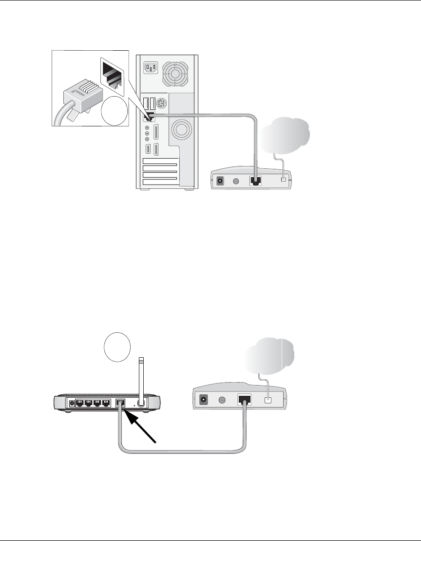
c. Locate the Ethernet cable (cable 1 in the diagram) that connects your PC to the modem.
Figure 3-1: Disconnect the Ethernet cable from the computer
d. Disconnect the cable at the computer end only, point A in the diagram.
e. Look at the label on the bottom of the router. Locate the Internet port. Securely insert the
Ethernet cable from your modem (cable 1 in the diagram below) into the Internet port of
the router as shown in point B of the diagram.
Figure 3-2: Connect the router to the modem
PRGHP
&DEOH
,QWHUQHW
FRPSXWHU
A
PRGHP
&DEOH
,QWHUQHW
,QWHUQHW
SRUW
URXWHU
B
Reference Manual for the MR814 v3 Cable/DSL Wireless Router
Connecting the Router to the Internet 3-3
202-10039-01
Note: Place the MR814 v3 router in a location which conforms to the “Observe
Performance, Placement, and Range Guidelines” on page 4-1. The stand provided with the
router provides a convenient, space-saving way of installing the router. Avoid stacking it
on other electronic equipment.
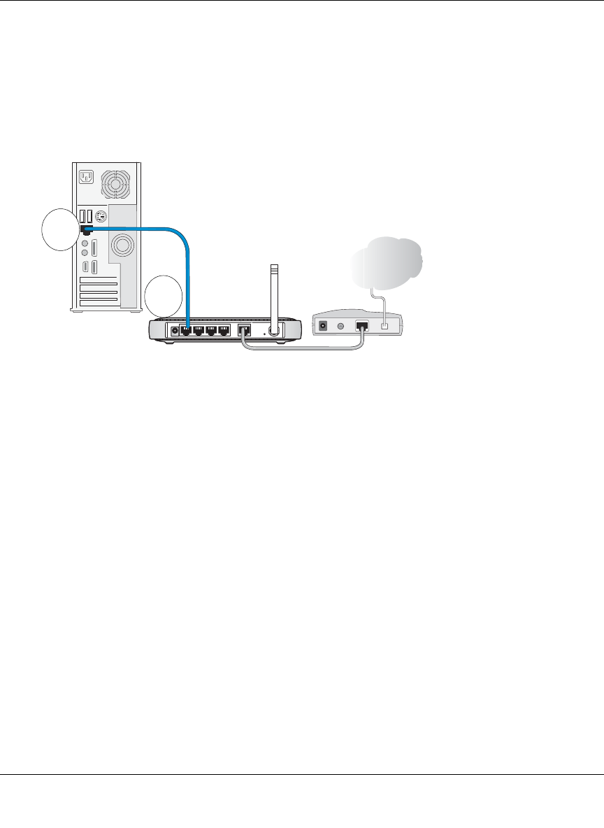
f. Securely insert the blue cable that came with your router (cable 2 in the diagram below)
into a LAN port on the router such as LAN port 4 (point C in the diagram), and the other
end into the Ethernet port of your computer (point D in the diagram).
Figure 3-3: Connect the computer to the router
Your network cables are connected and you are ready to restart your network.
2. RESTART YOUR NETWORK IN THE CORRECT SEQUENCE
Warning: Failure to restart your network in the correct sequence could prevent you from
connecting to the Internet.
a. First, turn on the broadband modem and wait 2 minutes.
b. Now, plug in the power cord to your router and wait 1 minute.
c. Last, turn on your computer.
Note: For DSL customers, if software logs you in to the Internet, do not run that software. You
may need to go to the Internet Explorer Tools menu, Internet Options, Connections tab page
where you can select “Never dial a connection.”
/$13RUWV
%OXH1(7*($5
&DEOH
,QWHUQHW
PRGHP
URXWHU
FRPSXWHU C
D
Reference Manual for the MR814 v3 Cable/DSL Wireless Router
3-4 Connecting the Router to the Internet
202-10039-01
Figure 3-4: Verify the connections according to the status lights on the router
d. Check the router status lights to verify the following:
•Power: The power light should turn solid green. If it does not, see “Troubleshooting
Tips” on page 3-8.
• Test: The test light blinks when the router is first turned on then goes off. If after 2
minutes it is still on, see “Troubleshooting Tips” on page 3-8.
•Internet: The Internet port light should be lit. If not, make sure the Ethernet cable is
securely attached to the router Internet port and the modem, and the modem is
powered on.
•Wireless: The Wireless light should be lit. If the Wireless light is not lit, see
“Troubleshooting Tips” on page 3-8.
•LAN: A LAN light should be lit. Green indicates your computer is communicating at
100 Mbps; yellow indicates 10 Mbps. If LAN light is not lit, check that the Ethernet
cable from the computer to the router is securely attached at both ends, and that the
computer is turned on.
3. USE THE SMART WIZARD TO CONFIGURE THE ROUTER
a. From the Ethernet connected PC you just set up, open a browser such as Internet Explorer
or Netscape® Navigator.
0OWER )NTERNET0ORT
7IRELESS ,!.0ORT
4EST
Reference Manual for the MR814 v3 Cable/DSL Wireless Router
Connecting the Router to the Internet 3-5
202-10039-01
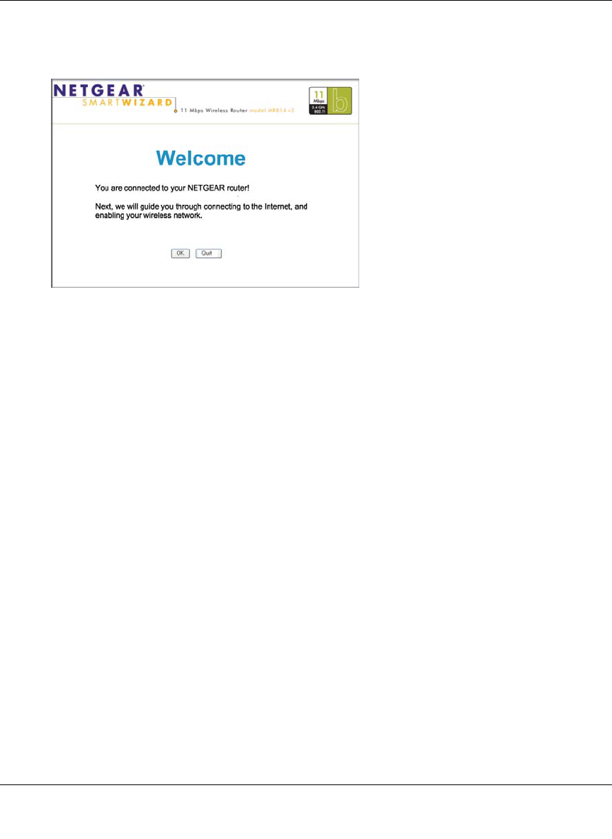
In its factory default state, the router will automatically display the NETGEAR Smart
Wizard configuration assistant welcome page.
Figure 3-5: NETGEAR Smart Wizard configuration assistant
Note: If you do not see this page, clear the browser cache by going to the Internet Explorer
Tools menu, Internet Options, and clicking Delete Files, then selecting the Delete all
offline files check box and clicking Ok.
If you still do not connect, type http://www.routerlogin.net in the browser address bar and
click Enter. Otherwise, to bypass this screen, see “How to Bypass the Configuration
Assistant” on page 3-12 and the “How to Manually Configure Your Internet Connection”
on page 3-13 topics in this chapter.
If you cannot connect to the router, verify your computer networking setup. It should be
set to obtain both IP and DNS server addresses automatically, which is usually so. For help
with this, see Appendix C, “Preparing Your Network” or the animated tutorials on the CD.
b. Click OK. Follow the prompts to proceed with the Smart Wizard configuration assistant to
connect to the Internet.
Reference Manual for the MR814 v3 Cable/DSL Wireless Router
3-6 Connecting the Router to the Internet
202-10039-01
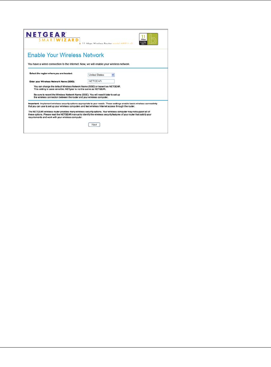
c. Follow the instructions on the screen to enable the wireless feature.
Figure 3-6: Enable the wireless feature
d. Enable your wireless network, click Next to proceed, then click Done to finish. If you
have trouble connecting to the Internet, see “Troubleshooting Tips” on page 3-8 to correct
basic problems.
Note: The Smart Wizard configuration assistant only appears when the router is in its
factory default state. After you configure the router, it will not appear again. You can
always connect to the router to change its settings. To do so, open a browser such as
Internet Explorer and go to http://www.routerlogin.net. Then, when prompted, enter
admin as the user name and password for the password both in lower case letters.
You are now connected to the Internet and the wireless feature of the router is enabled!
Next, configure your wireless computer.
Reference Manual for the MR814 v3 Cable/DSL Wireless Router
Connecting the Router to the Internet 3-7
202-10039-01
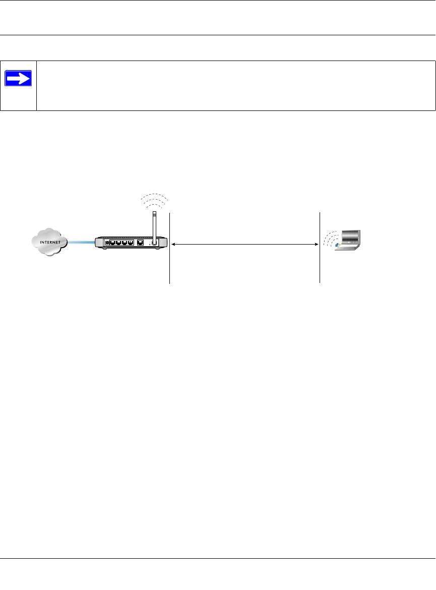
Now, Set Up a Computer for Wireless Connectivity
You are now connected to the Internet and the wireless feature of the router is enabled! Next,
configure your wireless computer.
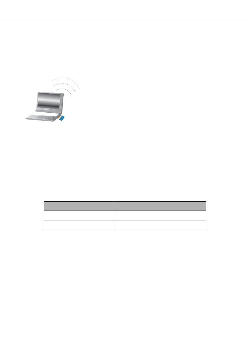
1. CONFIGURE THE COMPUTER’S WIRELESS ADAPTER SETTINGS
Figure 3-7: Configure wireless computer
NETGEAR, Inc. wireless adapters display a list of available wireless networks, and, when
wireless security is disabled, you simply choose yours from the list and connect.
For a non-NETGEAR wireless adapter, configure it to match your settings exactly. If you
changed the default Network Name (SSID), be sure to use the correct Network Name (SSID)
you set in the router.
Warning: The Network Name (SSID) is case sensitive. Entering nETgear will not work.
2. VERIFY WIRELESS CONNECTIVITY
Verify wireless connectivity. Connect to the Internet or log in to the router from a computer
with a wireless adapter. For wireless connectivity problems, see “Troubleshooting Tips” on
page 3-8.
You are now wirelessly connected to the Internet! Implement wireless security according to the
instructions in “Implement Appropriate Wireless Security” on page 4-2.”
WIRELESS FEATURE DEFAULT SETTING
Network Name (SSID) NETGEAR
WEP Security Disabled
:LUHOHVV$GDSWHULQD
1RWHERRN&RPSXWHU

Reference Manual for the MR814 v3 Cable/DSL Wireless Router
3-8 Connecting the Router to the Internet
202-10039-01
Troubleshooting Tips
Here are some tips for correcting simple problems you may have.
Be sure to restart your network in this sequence:
1) Turn off the modem, router, and computer; 2) Turn on the modem, wait two minutes; 3)
Turn on the router and wait 1 minute; 4) Turn on the computer.
Make sure the Ethernet cables are securely plugged in.
• The Internet status light on the router will be lit if the Ethernet cable to the router from the
modem is plugged in securely and the modem and router are turned on.
• For each powered on computer connected to the router with a securely plugged in Ethernet
cable, the corresponding router LAN port status light will be lit. The label on the bottom of the
router identifies the number of each LAN port.
Make sure the wireless settings in the computer and router match exactly.
The Wireless Network Name (SSID) and WEP settings of the router and wireless computer
must match exactly.
Make sure the network settings of the computer are correct.
• LAN and wirelessly connected computers must be configured to obtain an IP address
automatically via DHCP. Please see Appendix C, “Preparing Your Network” or the animated
tutorials on the CD for help with this.
• Some cable modem ISPs require you to use the MAC address of the computer registered on
the account. If so, in the Router MAC Address section of the Basic Settings menu, select, “Use
this Computer’s MAC Address.” The router will then capture and use the MAC address of the
computer that you are now using. You must be using the computer that is registered with the
ISP. Click Apply to save your settings. Restart the network in the correct sequence.
Check the router status lights to verify correct router operation.
• If the Power light does not turn solid green within 2 minutes after turning the router on, reset
the router according to the instructions in “Restoring the Default Configuration and Password”
on page 8-7.
• If the Wireless light does not come on, verify that the wireless feature is turned on according to
the instructions in “Restoring the Default Configuration and Password” on page 8-7.

Reference Manual for the MR814 v3 Cable/DSL Wireless Router
Connecting the Router to the Internet 3-9
202-10039-01
Overview of How to Access the Router
The table below describes how you access the router, depending on the state of the router.
Table 3-1. Ways to access the router
Router State Access Options Description
Factory Default
Note: The router is
supplied in the
factory default
state. Also, the
factory default state
is restored when you
use the factory reset
button. See
“Restoring the
Default
Configuration and
Password” on page
8-7 for more
information on this
feature.
Automatic Access via
the Smart Wizard
Configuration
Assistant
Any time a browser is opened on any computer connected to
the router, the router will automatically connect to that
browser and display the Configuration Assistant
welcome page.
There is no need to enter the router URL in the browser,
or provide the login user name and password.
Manually enter a URL
to bypass the Smart
Wizard Configuration
Assistant
You can bypass the Smart Wizard Configuration Assistant
feature by typing
http://www.routerlogin.net/basicsetting.htm
in the browser address bar and clicking Enter. You will not be
prompted for a user name or password.
This will enable you to manually configure the router even
when it is in the factory default state. When manually
configuring the router, you must complete the configuration
by clicking Apply when finished entering your settings. If you
do not do so, a browser on any PC connected to the router
will automatically display the router's Configuration Assistant
Welcome page rather than the browser’s home page.
Configuration
Settings Have
Been Applied
Enter the standard
URL to access the
router
Connect to the router by typing either of these URLs in the
address field of your browser, then click Enter:
•http://www.routerlogin.net
•http://www.routerlogin.com
The router will prompt you to enter the user name of admin
and the password. The default password is password.
Enter the IP address
of the router to
access the
Connect to the router by typing the IP address of the router in
the address field of your browser, then click Enter.
192.168.0.1 is the default IP address of the router. The router
will prompt you to enter the user name of admin and the
password. The default password is password.
Reference Manual for the MR814 v3 Cable/DSL Wireless Router
3-10 Connecting the Router to the Internet
202-10039-01
How to Log On to the Router After
Configuration Settings Have Been Applied
1. Connect to the router by typing http://www.routerlogin.net in the address field of your
browser, then click Enter.
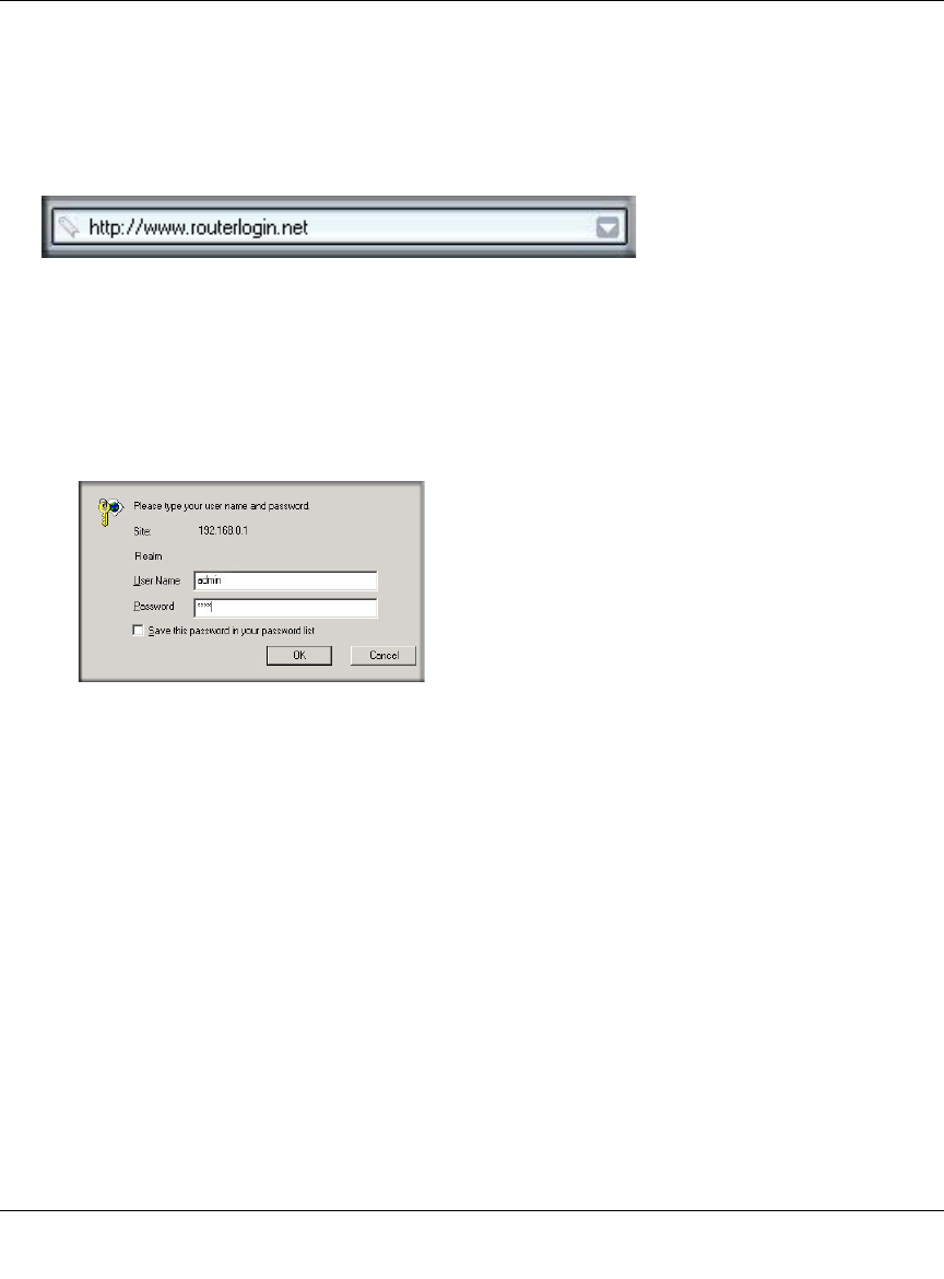
2. For security reasons, the router has its own user name and password. When prompted, enter
admin for the router user name and password for the router password, both in lower case
letters. To change the password, see “Changing the Administrator Password” on page 6-8
Note: The router user name and password are not the same as any user name or password you
may use to log in to your Internet connection.
A login window like the one shown below opens:
Figure 3-8: Login window
Once you have entered your user name and password, your Web browser should find the
MR814 v3 router and display the home page as shown in below.
Reference Manual for the MR814 v3 Cable/DSL Wireless Router
Connecting the Router to the Internet 3-11
202-10039-01
Figure 3-9: Login result: MR814 v3 home page
The browser will then display the MR814 v3 settings home page.
When the router is connected to the Internet, click the Knowledge Base or the Documentation link
under the Web Support menu to view support information or the documentation for the router.
If you do not click Logout, the router will wait 5 minutes after there is no activity before it
automatically logs you out.

Reference Manual for the MR814 v3 Cable/DSL Wireless Router
3-12 Connecting the Router to the Internet
202-10039-01
How to Bypass the Configuration Assistant
1. When the router is in the factory default state, type
http://www.routerlogin.net/basicsetting.htm in the address field of your browser, then click
Enter.
When the router is in the factory default state, a user name and password are not required.
2. The browser will then display the MR814 v3 settings home page shown in “Login result:
MR814 v3 home page” on page 3-11.
If you do not click Logout, the router will wait 5 minutes after there is no activity before it
automatically logs you out.

Reference Manual for the MR814 v3 Cable/DSL Wireless Router
Connecting the Router to the Internet 3-13
202-10039-01
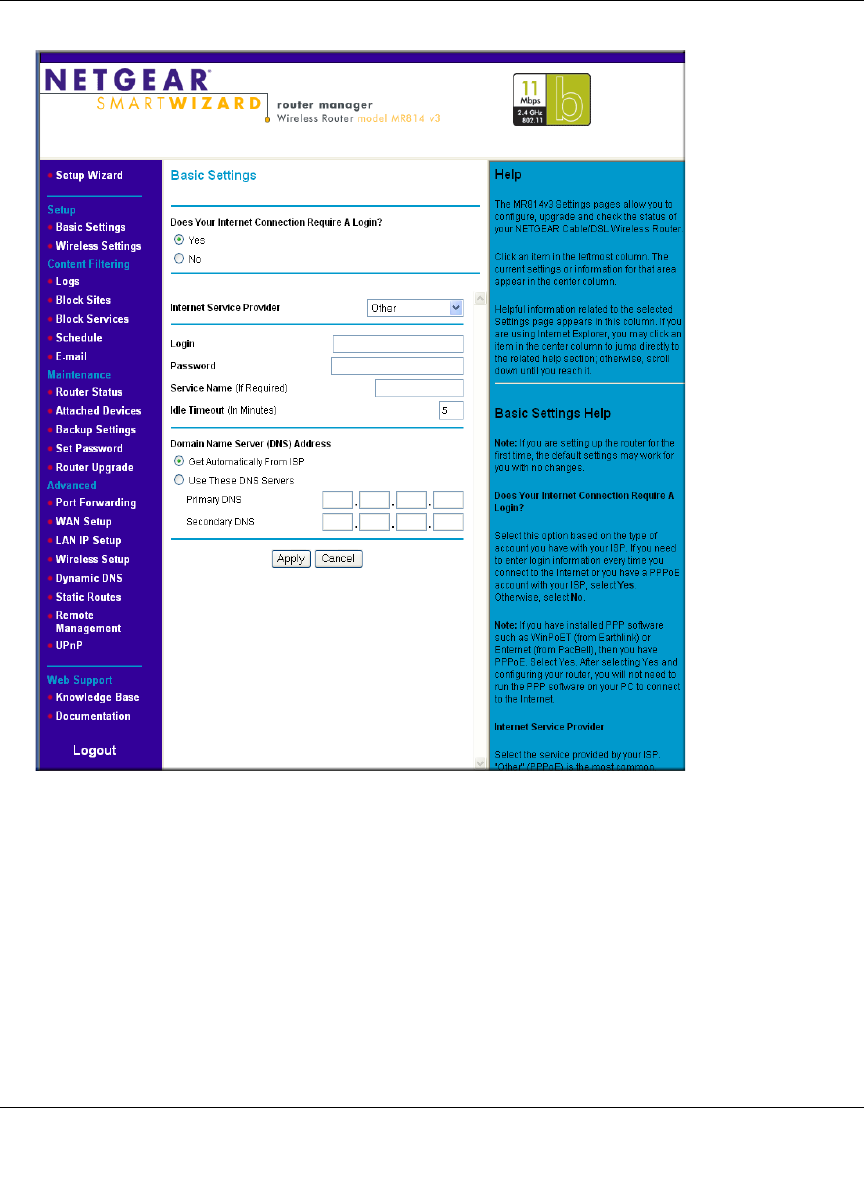
How to Manually Configure Your Internet Connection
You can manually configure your router using the menu below, or you can allow the Setup Wizard
to determine your configuration as described in the previous section.
Figure 3-10: Browser-based configuration Basic Settings menus
You can manually configure the router using the Basic Settings menu shown in Figure 3-10 using
these steps:
1. Connect to the router by typing http://www.routerlogin.net in the address field of your
browser, then click Enter.
ISP Does Not Require Login ISP Does Require Login

Reference Manual for the MR814 v3 Cable/DSL Wireless Router
3-14 Connecting the Router to the Internet
202-10039-01
2. For security reasons, the router has its own user name and password. When prompted, enter
admin for the router user name and password for the router password, both in lower case
letters.
3. Click Basic Settings on the Setup menu.
4. If your Internet connection does not require a login, click No at the top of the Basic Settings
menu and fill in the settings according to the instructions below. If your Internet connection
does require a login, click Yes, and skip to step 3.
a. Enter your Account Name (may also be called Host Name) and Domain Name.
These parameters may be necessary to access your ISP’s services such as mail or news
servers.
b. Internet IP Address:
If your ISP has assigned you a permanent, fixed (static) IP address for your computer,
select “Use static IP address”. Enter the IP address that your ISP assigned. Also enter the
netmask and the Gateway IP address. The Gateway is the ISP’s router to which your router
will connect.
c. Domain Name Server (DNS) Address:
If you know that your ISP does not automatically transmit DNS addresses to the router
during login, select “Use these DNS servers” and enter the IP address of your ISP’s
Primary DNS Server. If a Secondary DNS Server address is available, enter it also.
Note: If you enter an address here, restart the computers on your network so that these
settings take effect.
d. Gateway’s MAC Address:
This section determines the Ethernet MAC address that will be used by the router on the
Internet port. Some ISPs will register the Ethernet MAC address of the network interface
card in your computer when your account is first opened. They will then only accept
traffic from the MAC address of that computer. This feature allows your router to
masquerade as that computer by “cloning” its MAC address.
To change the MAC address, select “Use this Computer’s MAC address.” The router
will then capture and use the MAC address of the computer that you are now using. You
must be using the one computer that is allowed by the ISP. Or, select “Use this MAC
address” and enter it.
e. Click Apply to save your settings.
5. If your Internet connection does require a login, fill in the settings according to the instructions
below. Select Yes if you normally must launch a login program such as Enternet or WinPOET
in order to access the Internet.
Reference Manual for the MR814 v3 Cable/DSL Wireless Router
Connecting the Router to the Internet 3-15
202-10039-01
Note: After you finish setting up your router, you will no longer need to launch the ISP’s login
program on your computer in order to access the Internet. When you start an Internet
application, your router will automatically log you in.
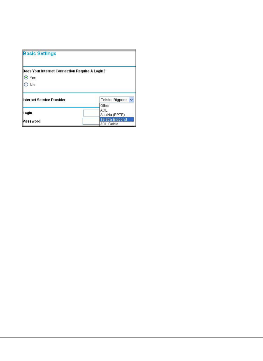
a. Select you Internet service provider from the drop-down list.
Figure 3-11: Basic Settings ISP list
Note: Not all ISPs are listed here. The ones on this list have special requirements.
b. The screen will change according to the ISP settings requirements of the ISP you select.
c. Fill in the parameters for your Internet service provider.
d. Click Apply to save your settings. Click the Test button to verify you have Internet access.
Using the Smart Setup Wizard
You can use the Smart Setup Wizard to assist with manual configuration or to verify the Internet
connection. The Smart Setup Wizard is not the same as the Smart Wizard configuration assistant
(as illustrated in Figure 3-5) that only appears when the router is in its factory default state. After
you configure the router, the Smart Wizard configuration assistant will not appear again.
To use the Smart Setup Wizard to assist with manual configuration or to verify the Internet
connection settings, follow this procedure.
1. Connect to the router by typing http://www.routerlogin.net in the address field of your
browser, then click Enter.

Reference Manual for the MR814 v3 Cable/DSL Wireless Router
3-16 Connecting the Router to the Internet
202-10039-01
2. For security reasons, the router has its own user name and password. When prompted, enter
admin for the router user name and password for the router password, both in lower case
letters. To change the password, see “Changing the Administrator Password” on page 6-8
Note: The router user name and password are not the same as any user name or password you
may use to log in to your Internet connection.
Once you have entered your user name and password, your Web browser should find the
MR814 v3 router and display the home page as shown in “Login result: MR814 v3 home
page” on page 3-11.
3. Click Setup Wizard on the upper left of the main menu.
4. Click Next to proceed. Input your ISP settings, as needed.
5. At the end of the Setup Wizard, click the Test button to verify your Internet connection. If you
have trouble connecting to the Internet, use the Troubleshooting Tips “Troubleshooting Tips”
on page 3-8 to correct basic problems, or refer to Chapter 8, “Troubleshooting.”
The topics below describe each of the various options the Smart Wizard can detect. Use this
information to assist you with filling in the menus.
NETGEAR product registration, support, and documentation
Register your product at http://www.NETGEAR.com/register. Registration is required before
you can use our telephone support service.
Product updates and web support are always available by going to:
http://kbserver.netgear.com/products/MR814v3.asp.
Documentation is available on the CD and at
http://kbserver.netgear.com/documentation/MR814v3.asp.
When the router is connected to the Internet, click the Knowledge Base or the Documentation link
under the Web Support menu to view support information or the documentation for the router.
Wireless Configuration 4-1
202-10039-01
Chapter 4
Wireless Configuration
This chapter describes how to configure the wireless features of your MR814 v3 router. In
planning your wireless network, you should consider the level of security required. You should
also select the physical placement of your firewall in order to maximize the network speed. For
further information on wireless networking, refer to in Appendix D, “Wireless Networking
Basics.”
Observe Performance, Placement, and Range Guidelines
The operating distance or range of your wireless connection can vary significantly based on the
physical placement of the wireless firewall. The latency, data throughput performance, and
notebook power consumption also vary depending on your configuration choices.
For best results, place your firewall:
• Near the center of the area in which your PCs will operate.
• In an elevated location such as a high shelf where the wirelessly connected PCs have
line-of-sight access (even if through walls).
• Away from sources of interference, such as PCs, microwaves, and 2.4 GHz cordless phones.
• Away from large metal surfaces.
The time it takes to establish a wireless connection can vary depending on both your security
settings and placement. WEP connections can take slightly longer to establish. Also, WEP
encryption can consume more battery power on a notebook PC.
Note: Failure to follow these guidelines can result in significant performance
degradation or inability to wirelessly connect to the router. For complete range/
performance specifications, please see Appendix A, “Technical Specifications.”
Reference Manual for the MR814 v3 Cable/DSL Wireless Router
4-2 Wireless Configuration
202-10039-01
Implement Appropriate Wireless Security
Unlike wired network data, your wireless data transmissions can be received well beyond your
walls by anyone with a compatible adapter. For this reason, use the security features of your
wireless equipment. The MR814 v3 router provides highly effective security features which are
covered in detail in this chapter. Deploy the security features appropriate to your needs.
Figure 4-1: MR814 v3 wireless data security options
There are several ways you can enhance the security of you wireless network.
•Restrict Access Based on MAC Address. You can restrict access to only trusted computers o
that unknown computers cannot wirelessly connect to the MR814 v3. MAC address filtering
adds an obstacle against unwanted access to your network, but the data broadcast over the
wireless link is fully exposed.
•WEP. Wired Equivalent Privacy (WEP) data encryption provides data security. WEP Shared
Key authentication and WEP data encryption will block all but the most determined
eavesdropper.
•WPA-PSK. Wi-Fi Protected Access (WPA) data encryption provides strong data security.
WPA-PSK will block eavesdropping. Because this is a new standard, wireless device driver
and software availability may be limited.
Note: Indoors, computers can connect over 802.11 wireless networks at ranges
of up to 300 feet. Such distances can allow for others outside of your immediate area to
access your network.
:LUHOHVV'DWD
6HFXULW\2SWLRQV
5DQJHXSWRIRRWUDGLXV
2SHQV\VWHPHDV\EXWQRVHFXULW\
0$&DFFHVVOLVWQRGDWDVHFXULW\
:(3VHFXULW\EXWVRPHSHUIRUPDQFHLPSDFW
:3$36.YHU\VWURQJVHFXULW\
MR814 v3
Reference Manual for the MR814 v3 Cable/DSL Wireless Router
Wireless Configuration 4-3
202-10039-01
•Turn Off the Wireless LAN. If you disable the wireless LAN, wireless devices cannot
communicate with the router at all. You might choose to turn off the wireless the LAN when
you are away and the others in the household all use wired connections.
•Turn Off the Broadcast of the Wireless Network Name SSID. If you disable broadcast of
the SSID, only devices that have the correct SSID can connect. This nullifies the wireless
network ‘discovery’ feature of some products such as Windows XP, but the data is still fully
exposed to a determined snoop using specialized test equipment like wireless sniffers.
Understanding Wireless Settings
This section identifies the default factory settings and introduces each wireless option.
Default Factory Settings
When you first receive your MR814 v3, the default factory settings are shown below. You can
restore these defaults with the Factory Default Restore button on the rear panel. After you install
the MR814 v3 router, use the procedures below to customize any of the settings to better meet
your networking needs.
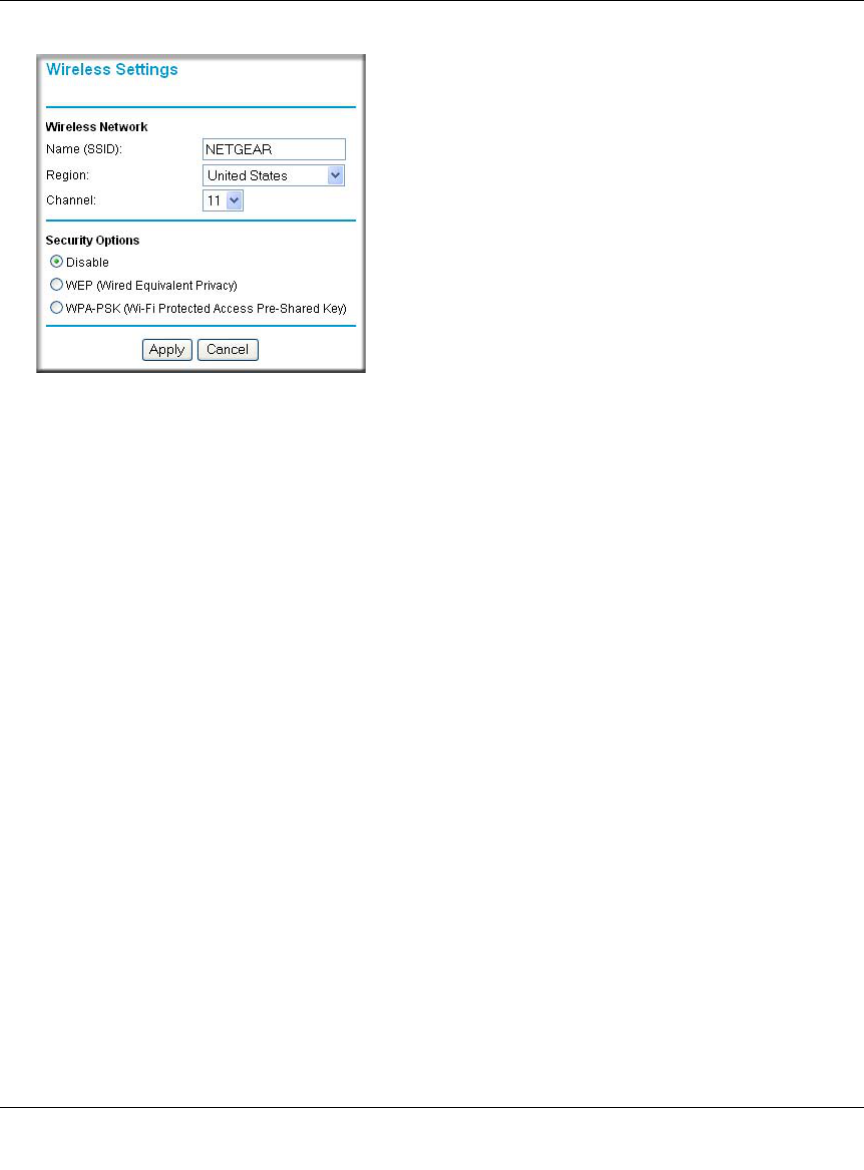
Basic Wireless Settings
To configure the wireless settings of your router, click the Wireless link in the main menu of the
browser interface. The Wireless Settings menu will appear, as shown below.
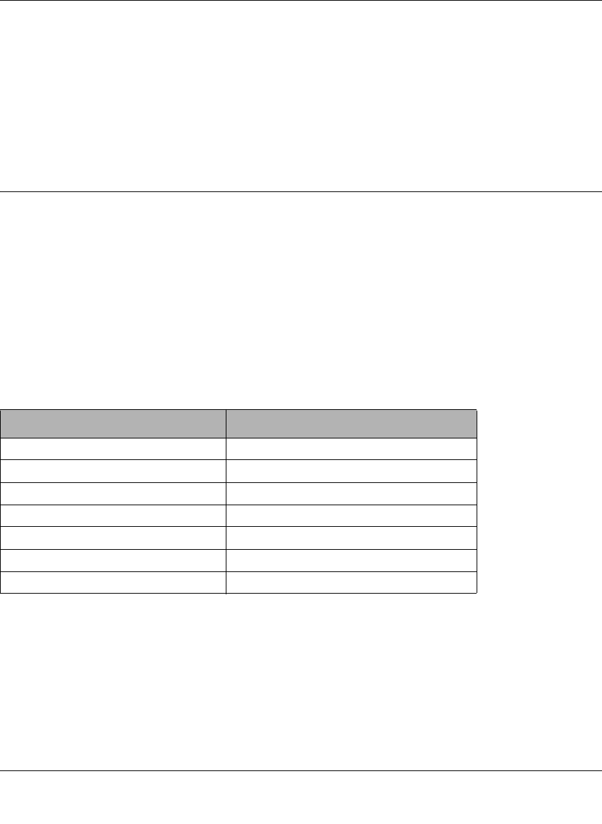
FEATURE DEFAULT FACTORY SETTINGS
Wireless Access Point Enabled
Wireless Access List (MAC Filtering) All wireless stations allowed
SSID broadcast Enabled
SSID NETGEAR
11b RF Channel 11
Authentication Type Automatic
Wireless Security Options Disabled
Reference Manual for the MR814 v3 Cable/DSL Wireless Router
4-4 Wireless Configuration
202-10039-01
Figure 4-2: Wireless Settings menu
•Name (SSID). The SSID is also known as the wireless network name. Enter a value of up to
32 alphanumeric characters. In a setting where there is more than one wireless network,
different wireless network names provide a means for separating the traffic. Any device you
want to participate in a particular wireless network will need to use this SSID for that network.
The MR814 v3 default SSID is: NETGEAR.
•Region. This field identifies the region where the MR814 v3 can be used. It may not be legal
to operate the wireless features of the router in a region other than one of those identified in
this field.
•Channel. This field determines which operating frequency will be used. It should not be
necessary to change the wireless channel unless you notice interference problems with another
nearby access point. For more information on the wireless channel frequencies please refer to
“Wireless Channels” on page D-2.
•Security Options. These options are the wireless security features you can enable. The table
below identifies the various basic wireless security options. A full explanation of these
standards is available in Appendix D, “Wireless Networking Basics.

Reference Manual for the MR814 v3 Cable/DSL Wireless Router
Wireless Configuration 4-5
202-10039-01
Table 4-1. Security Options
Field Description
Disable No wireless security.
WEP WEP offers the following options:
• Automatic
Normally, this can be left to the default setting of automatic. When set to Automatic, the
MR814 v3 will make a best effort attempt to use whatever options the wireless station is
using. If this fails, you may need to configure this setting so that the MR814 v3 router and
wireless stations match.
• Open System
With Open Network Authentication and 64- or 128-bit WEP Data Encryption, the MR814 v3
does perform 64- or 128-bit data encryption but does not perform any authentication.
• Shared Key
Shared Key authentication encrypts the SSID and data.
Choose the Encryption Strength (64- or 128-bit data encryption). Manually enter the key
values or enter a word or group of printable characters in the Passphrase box. Manually
entered keys are case sensitive but passphrase characters are not case sensitive.
Note: Not all wireless adapter configuration utilities support WEP passphrase key
generation.
WPA-PSK WPA-Pre-shared Key performs authentication, uses 128-bit data encryption, and dynamically
changes the encryption keys making it nearly impossible to circumvent.
• Passphrase
Enter a word or group of between 8-63 printable characters in the Passphrase box. These
characters are case sensitive.
• Key Lifetime
This setting determines how often the encryption key is changed. Shorter periods provide
greater security, but adversely affect performance. If desired, you can change the default
value.
Note: Not all wireless adapter configuration utilities support WPA. Furthermore, client software
is required on the client. Windows XP and Windows 2000 with Service Pack 3 do include the
client software that supports WPA. Nevertheless, the wireless adapter hardware and driver
must also support WPA.
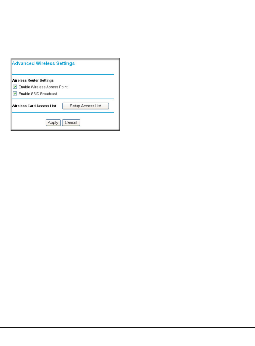
Reference Manual for the MR814 v3 Cable/DSL Wireless Router
4-6 Wireless Configuration
202-10039-01
Advanced Wireless Settings
To configure the advanced wireless settings of your firewall, click the Wireless Setup link in the
Advanced section of the main menu of the browser interface. The Wireless Settings menu will
appear, as shown below.
Figure 4-3: Advanced Wireless Settings menu
•Allow Broadcast of Name (SSID). If you disable broadcast of the SSID, only devices that
have the correct SSID can connect. Disabling SSID broadcast nullifies the wireless network
‘discovery’ feature of some products such as Windows XP.
•Enable Wireless Access Point. If you disable the wireless access point, wireless devices
cannot connect to the MR814 v3.
•Wireless Card Access List. When the Trusted PCs Only radio button is selected, the MR814
v3 checks the MAC address of the wireless station and only allows connections to computers
identified on the trusted computers list.

Reference Manual for the MR814 v3 Cable/DSL Wireless Router
Wireless Configuration 4-7
202-10039-01
Information to Gather Before Changing Basic Wireless Settings
Before customizing your wireless settings, print this form and record the following information. If
you are working with an existing wireless network, the person who set up or is responsible for the
network will be able to provide this information. Otherwise, you will choose the settings for your
wireless network. Either way, record the settings for your wireless network in the spaces below.
•Wireless Network Name (SSID): ______________________________ The SSID, identifies
the wireless network. You can use up to 32 alphanumeric characters. The SSID is case
sensitive. The SSID in the wireless adapter card must match the SSID of the router. In some
configuration utilities (such as in Windows XP), the term “wireless network name” is used
instead of SSID.
•If WEP Authentication is Used. Circle one: Open System, Shared Key, or Auto.
Note: If you select Shared Key, the other devices in the network will not connect unless they
are set to Shared Key as well and are configured with the correct key.
–WEP Encryption key size. Choose one: 64-bit or 128-bit. Again, the encryption key size
must be the same for the wireless adapters and the router.
–Data Encryption (WEP) Keys. There are two methods for creating WEP data encryption
keys. Whichever method you use, record the key values in the spaces below.
•Passphrase method. ______________________________ These characters are case
sensitive. Enter a word or group of printable characters and click the Generate Keys
button. Not all wireless devices support the passphrase method.
•Manual method. These values are not case sensitive. For 64-bit WEP, enter 10 hex
digits (any combination of 0-9 or a-f). For 128-bit WEP, enter 26 hex digits.
Key 1: ___________________________________
Key 2: ___________________________________
Key 3: ___________________________________
Key 4: ___________________________________
Note: Key values and key identities (for example Key 1, Key 2, etc.) must match on all
wireless devices. However, not all wireless configuration utilities identify the keys in the
same way. For example, Windows XP Key 0 corresponds to Key 1 in most other products.
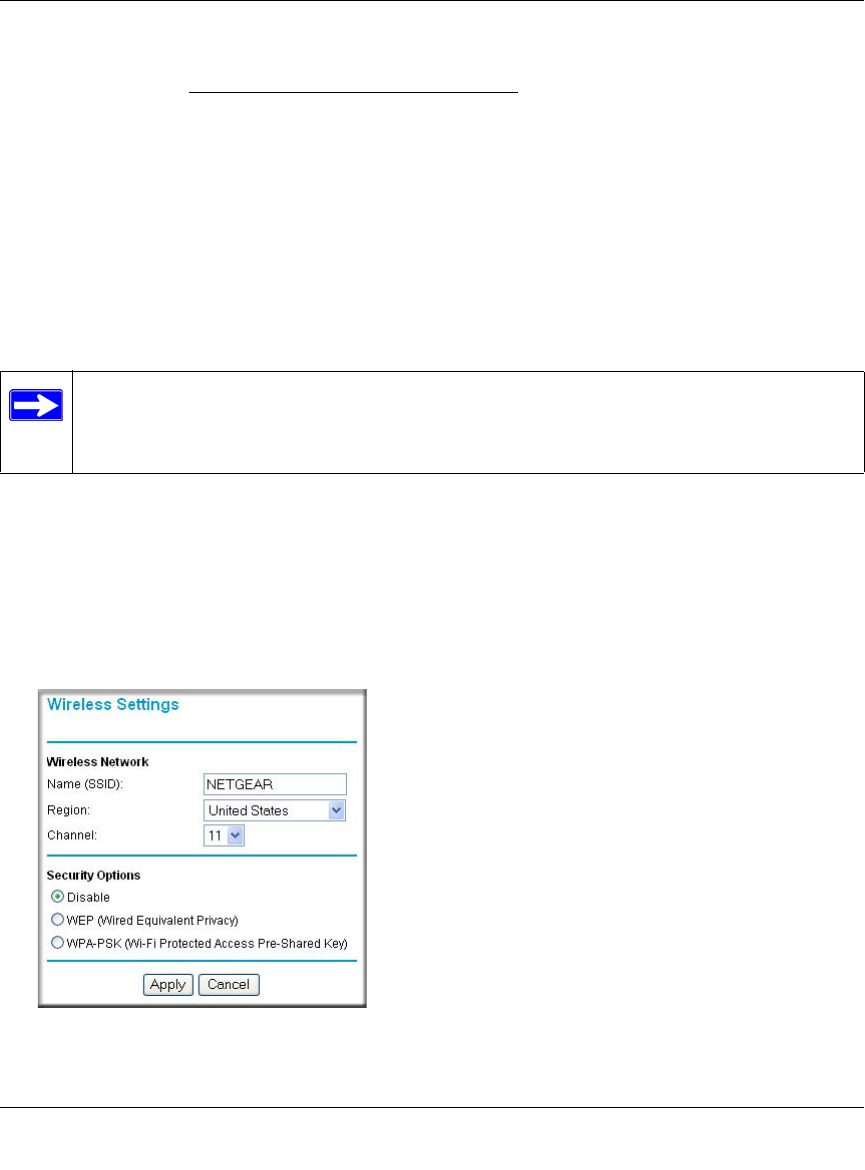
Reference Manual for the MR814 v3 Cable/DSL Wireless Router
4-8 Wireless Configuration
202-10039-01
•If WPA-PSK Authentication is Used.
–Passphrase: ______________________________ These characters are case sensitive.
Enter a word or group of printable characters. When you use WPA-PSK, the other devices
in the network will not connect unless they are set to WPA-PSK as well and are configured
with the correct Passphrase.
Use the procedures described in the following sections to configure the MR814 v3. Store this
information in a safe place.
How to Set Up and Test Basic Wireless Connectivity
Follow the instructions below to set up and test basic wireless connectivity. Once you have
established basic wireless connectivity, you can enable security settings appropriate to your needs.
1. Log in to the MR814 v3 firewall at http://www.routerlogin.net with its default user name of
admin and default password of password, or using whatever LAN address and password you
have set up.
2. Click Wireless Settings in the main menu of the MR814 v3 firewall.
Figure 4-4: Wireless Settings menu
Note: If you use a wireless computer to configure WPA settings, you will be
disconnected when you click Apply. Reconfigure your wireless adapter to match the
new settings or access the router from a wired computer to make any further changes.
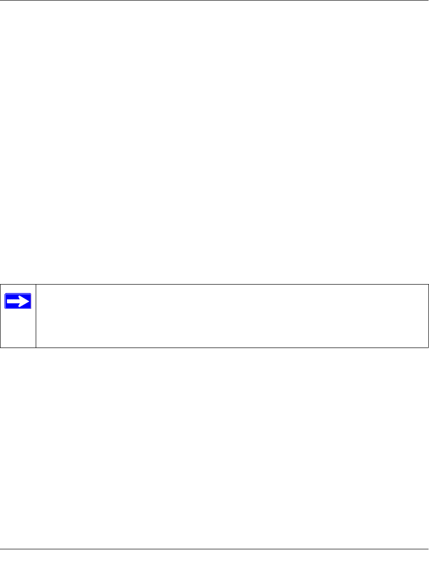
Reference Manual for the MR814 v3 Cable/DSL Wireless Router
Wireless Configuration 4-9
202-10039-01
3. Choose a suitable descriptive name for the wireless network name (SSID). In the SSID box,
enter a value of up to 32 alphanumeric characters. The default SSID is NETGEAR.
Note: The SSID is case sensitive; NETGEAR is not the same as nETgear. Also, the SSID of
any wireless access adapters must match the SSID you configure in the MR814 v3 Cable/DSL
Wireless Router. If they do not match, you will not get a wireless connection to the MR814 v3.
4. Set the Region. Select the region in which the wireless interface will operate.
5. Set the Channel. The default channel is 11.
This field determines which operating frequency will be used. It should not be necessary to
change the wireless channel unless you notice interference problems with another nearby
wireless router or access point. Select a channel that is not being used by any other wireless
networks within several hundred feet of your firewall and at least 5 channel positions from the
others in use. For more information on the wireless channel frequencies please refer to
“Wireless Channels” on page D-2.
6. For initial configuration and test, leave the Wireless Card Access List set to “Everyone” and
the Encryption Strength set to “Disabled.”
7. Click Apply to save your changes.
8. Configure and test your computers for wireless connectivity.
Program the wireless adapter of your computers to have the same SSID and channel that you
configured in the router. Check that they have a wireless link and are able to obtain an IP
address by DHCP from the firewall.
Warning: The Network Name (SSID) is case sensitive. If NETGEAR is the Network Name
(SSID) in your router, you must enter NETGEAR in your computer's wireless settings.
Entering nETgear will not work.
Once your computers have basic wireless connectivity to the firewall, then you can configure the
advanced wireless security functions of the firewall.
Note: If you are configuring the firewall from a wireless computer and you change the
firewall’s SSID, channel, or security settings, you will lose your wireless connection
when you click on Apply. You must then change the wireless settings of your computer
to match the firewall’s new settings.
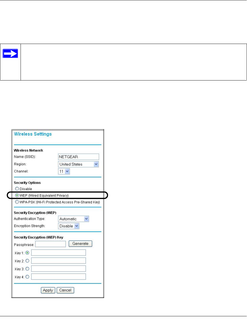
Reference Manual for the MR814 v3 Cable/DSL Wireless Router
4-10 Wireless Configuration
202-10039-01
How to Configure WEP
To configure WEP data encryption, follow these steps:
1. Log in to the MR814 v3 firewall at http://www.routerlogin.net with its default user name of
admin and default password of password, or using whatever LAN address and password you
have set up.
2. Click Wireless Settings in the main menu of the MR814 v3 firewall.
3. From the Security Options menu, select WEP. The WEP options display.
Figure 4-5. Wireless Settings encryption menu
Note: If you use a wireless computer configure WEP settings, you will be disconnected
when you click on Apply. You must then either configure your wireless adapter to match
the router WEP settings or access the router from a wired computer to make any further
changes.

Reference Manual for the MR814 v3 Cable/DSL Wireless Router
Wireless Configuration 4-11
202-10039-01
4. Select the Authentication Type and Encryptions strength from the drop-down lists.
5. You can manually or automatically program the four data encryption keys. These values must
be identical on all computers and Access Points in your network.
• Automatic - Enter a word or group of printable characters in the Passphrase box and click
the Generate button. The passphrase is case sensitive; NETGEAR is not the same as
nETgear. The four key boxes will be automatically populated with key values.
• Manual - Enter ten hexadecimal digits (any combination of 0-9, a-f, or A-F). These entries
are not case sensitive; AA is the same as aa.
Select which of the four keys will be active.
Please refer to “Overview of WEP Parameters” on page D-6 for a full explanation of each of
these options, as defined by the IEEE 802.11 wireless communication standard.
6. Click Apply to save your settings.
How to Configure WPA-PSK Wireless Security
Note: Not all wireless adapters support WPA. Furthermore, client software is also required.
Windows XP service pack 1 and Windows 2000 with service pack 3 do include WPA support.
Nevertheless, the wireless adapter hardware and driver must also support WPA. For instructions
on configuring wireless computers or PDAs for WPA-PSK security, consult the documentation for
the product you are using.
To configure WPA-PSK, follow these steps:
1. Click Wireless Settings the main menu and select WPA-PSK for the Security Option.
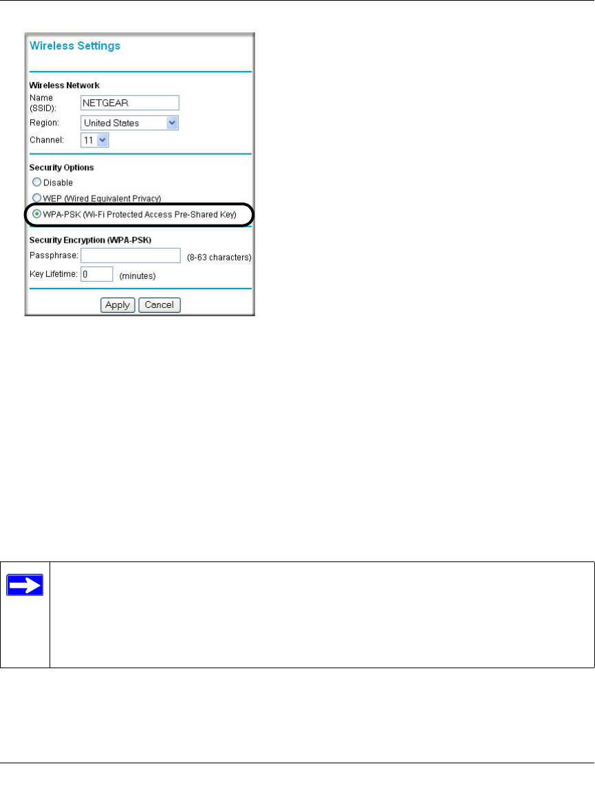
Reference Manual for the MR814 v3 Cable/DSL Wireless Router
4-12 Wireless Configuration
202-10039-01
Figure 4-6: WPA Settings menu
2. Enter a word or group of 8-63 printable characters in the Password Phrase box.
3. Click Apply to save your settings.
How to Restrict Wireless Access by MAC Address
To restrict access based on MAC Addresses, follow these steps:
1. Log in to the MR814 v3 firewall at http://www.routerlogin.net with its default user name of
admin and default password of password, or using whatever LAN address and password you
have set up.
2. Click Wireless Settings in the Advanced section of the main menu of the MR814 v3.
3. Click Setup Access List to display the Wireless Station Access List menu.
Note: When configuring the firewall from a wireless computer whose MAC address is
not in the Trusted PC list, if you select Turn Access Control On, you will lose your
wireless connection when you click on Apply. You must then access the router from a
wired computer or from a wireless computer which is on the access control list to make
any further changes.
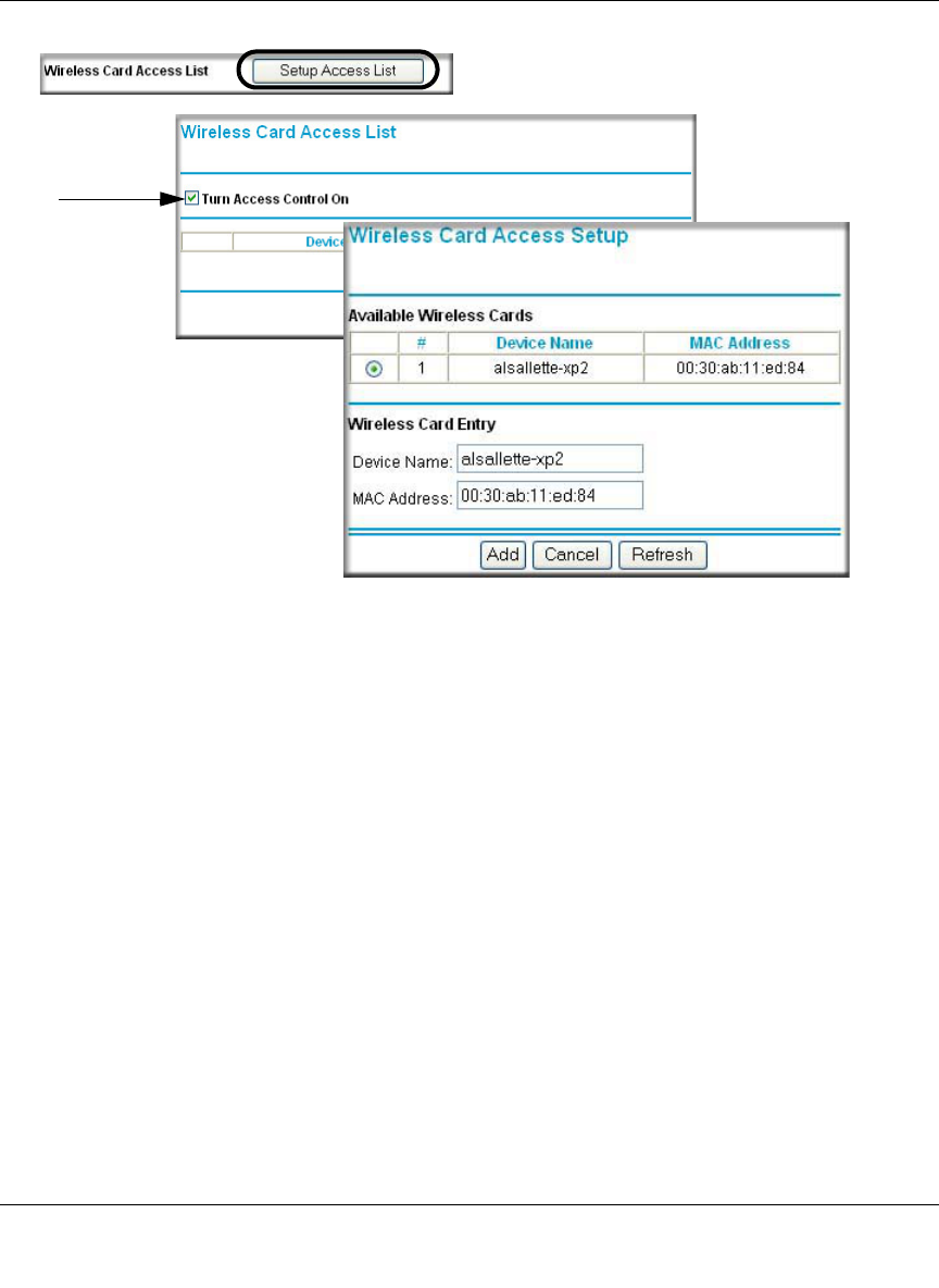
Reference Manual for the MR814 v3 Cable/DSL Wireless Router
Wireless Configuration 4-13
202-10039-01
Figure 4-7: Wireless Card Access List Setup
4. Click the Turn Access Control On check box.
5. Click Add to add a wireless device to the wireless access control list. The Wireless Card
Access Setup menu displays.
6. Then, either select from the list of available wireless cards the MR814 v3 has found in your
area, or enter the MAC address and device name for a device you plan to use. You can usually
find the MAC address printed on the wireless adapter.
Note: You can copy and paste the MAC addresses from the firewall’s Attached Devices menu
into the MAC Address box of this menu. To do this, configure each wireless computer to
obtain a wireless link to the firewall. The computer should then appear in the Attached
Devices menu.
7. Click Add to add this wireless device to the Wireless Card Access List. The screen changes
back to the list screen. Repeat these steps for each additional device you wish to add to the list.
8. Be sure to click Apply to save your wireless access control list settings.
Now, only devices on this list will be allowed to wirelessly connect to the MR814 v3.

Reference Manual for the MR814 v3 Cable/DSL Wireless Router
4-14 Wireless Configuration
202-10039-01

Content Filtering 5-1
202-10039-01
Chapter 5
Content Filtering
This chapter describes how to use the content filtering features of the MR814 v3 Cable/DSL
Wireless Router to protect your network. These features can be found by clicking on the Content
Filtering heading in the Main Menu of the browser interface.
Content Filtering Overview
The MR814 v3 Cable/DSL Wireless Router provides you with Web content filtering options, plus
browsing activity reporting and instant alerts via e-mail. Parents and network administrators can
establish restricted access policies based on time-of-day, web addresses and web address
keywords. You can also block Internet access by applications and services, such as chat or games.
To configure these features of your router, click on the subheadings under the Content Filtering
heading in the Main Menu of the browser interface. The subheadings are described below:
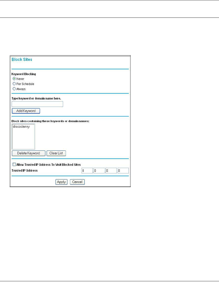
Reference Manual for the MR814 v3 Cable/DSL Wireless Router
5-2 Content Filtering
202-10039-01
Blocking Access to Internet Sites
The MR814 v3 router allows you to restrict access based on web addresses and web address
keywords. Up to 255 entries are supported in the Keyword list. The Block Sites menu is shown in
Figure 5-1 below:
Figure 5-1: Block Sites menu
To enable keyword blocking, select either “Per Schedule” or “Always”, then click Apply. If you
want to block by schedule, be sure that a time period is specified in the Schedule menu.
To add a keyword or domain, type it in the Keyword box, click Add Keyword, then click Apply.
To delete a keyword or domain, select it from the list, click Delete Keyword, then click Apply.
Keyword application examples:
• If the keyword “XXX” is specified, the URL <http://www.badstuff.com/xxx.html> is blocked.
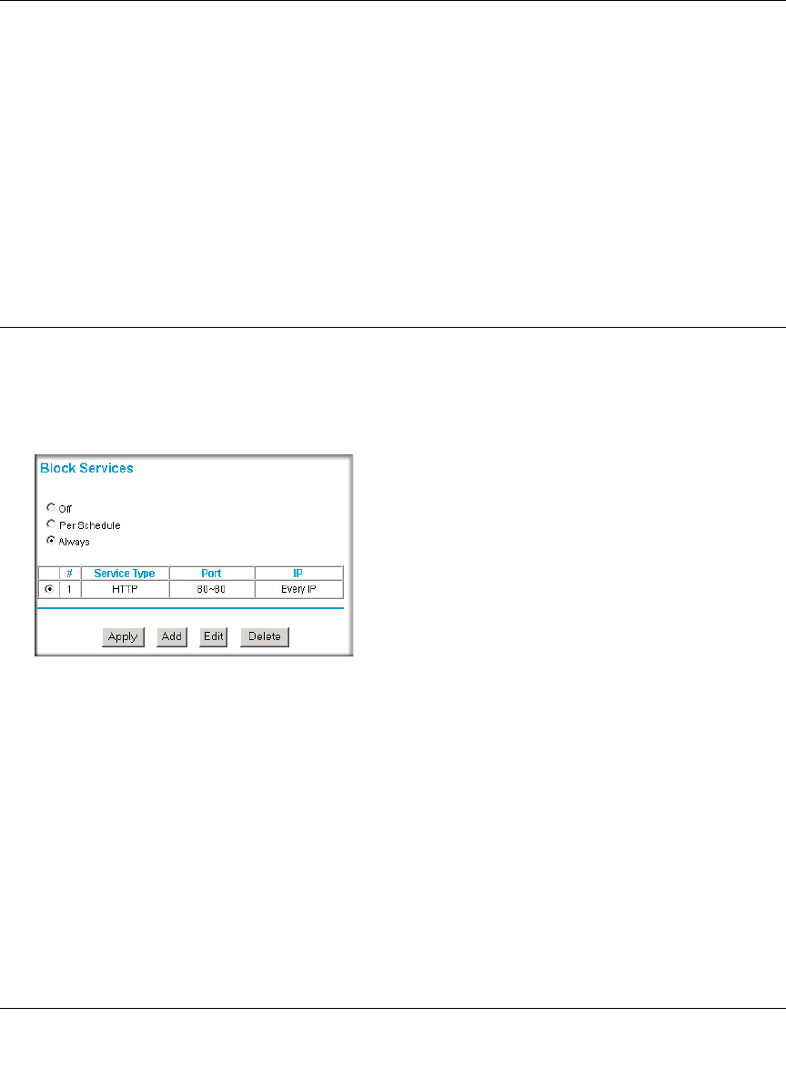
Reference Manual for the MR814 v3 Cable/DSL Wireless Router
Content Filtering 5-3
202-10039-01
• If the keyword “.com” is specified, only Web sites with other domain suffixes (such as .edu or
.gov) can be viewed.
• If you wish to block all Internet browsing access during a scheduled period, enter the keyword
“.” and set the schedule in the Schedule menu.
To specify a Trusted User, enter that PC’s IP address in the Trusted User box and click Apply.
You may specify one Trusted User, which is a PC that will be exempt from blocking and
logging. Since the Trusted User will be identified by an IP address, you should configure that
PC with a fixed IP address.
Blocking Access to Internet Services
The MR814 v3 router allows you to block the use of certain Internet services by PCs on your
network. This is called services blocking or port filtering. The Block Services menu is shown
below:
Figure 5-2: Block Services menu
Services are functions performed by server computers at the request of client computers. For
example, Web servers serve web pages, time servers serve time and date information, and game
hosts serve data about other players’ moves. When a computer on your network sends a request for
service to a server computer on the Internet, the requested service is identified by a service or port
number. This number appears as the destination port number in the transmitted IP packets. For
example, a packet that is sent with destination port number 80 is an HTTP (Web server) request.
To enable service blocking, select either Per Schedule or Always, then click Apply. If you want to
block by schedule, be sure that a time period is specified in the Schedule menu.
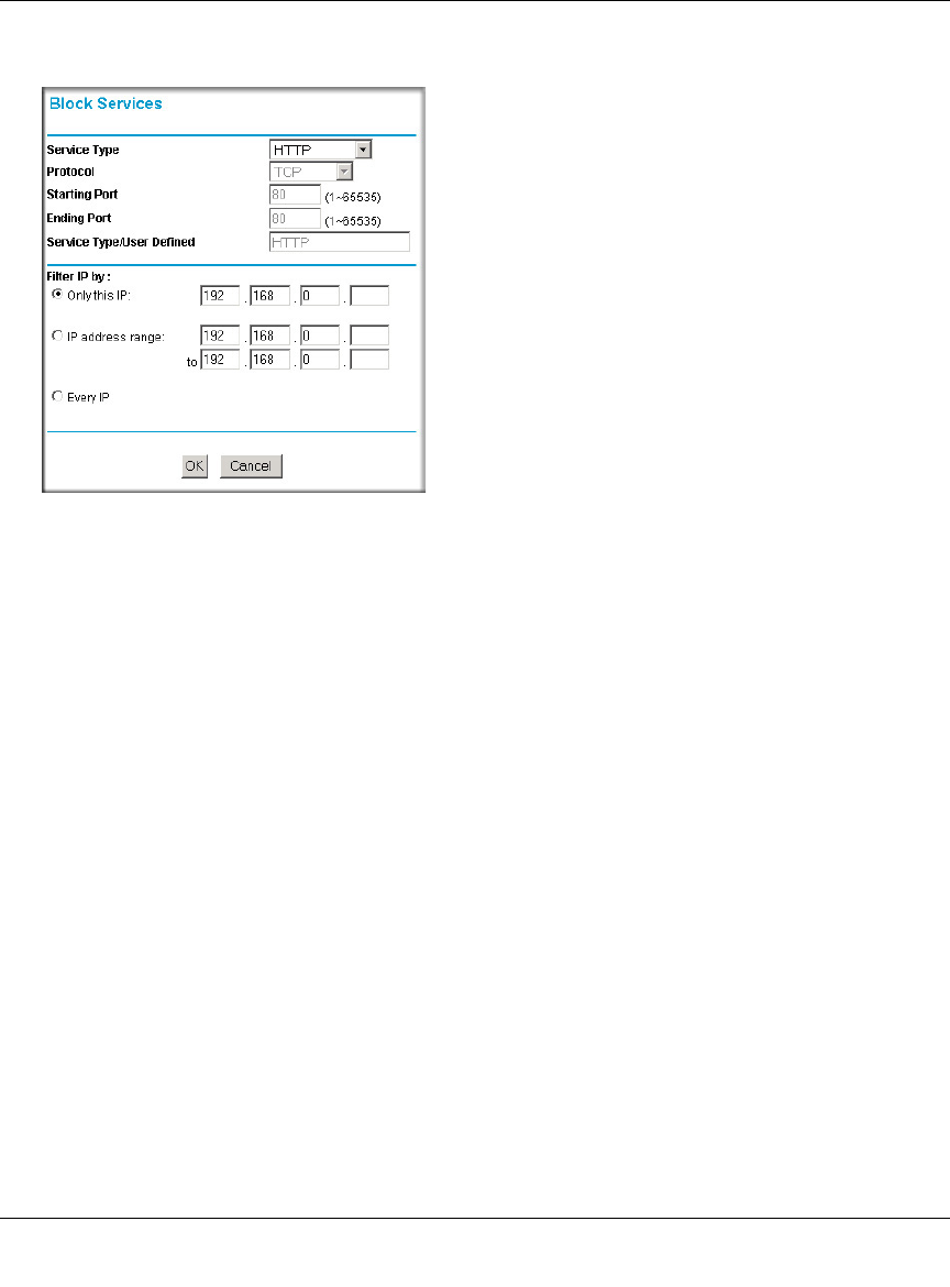
Reference Manual for the MR814 v3 Cable/DSL Wireless Router
5-4 Content Filtering
202-10039-01
To specify a service for blocking, click Add. The Add Services menu will appear, as shown below:
Figure 5-3: Add Services menu
From the Service Type list, select the application or service to be allowed or blocked. The list
already displays several common services, but you are not limited to these choices. To add any
additional services or applications that do not already appear, select User Defined.
Configuring a User Defined Service
To define a service, first you must determine which port number or range of numbers is used by
the application. The service numbers for many common protocols are defined by the Internet
Engineering Task Force (IETF) and published in RFC1700, “Assigned Numbers.” Service
numbers for other applications are typically chosen from the range 1024 to 65535 by the authors of
the application. This information can usually be determined by contacting the publisher of the
application or from user groups of newsgroups.
Enter the Starting Port and Ending Port numbers. If the application uses a single port number, enter
that number in both boxes.
If you know that the application uses either TCP or UDP, select the appropriate protocol. If you are
not sure, select Both.
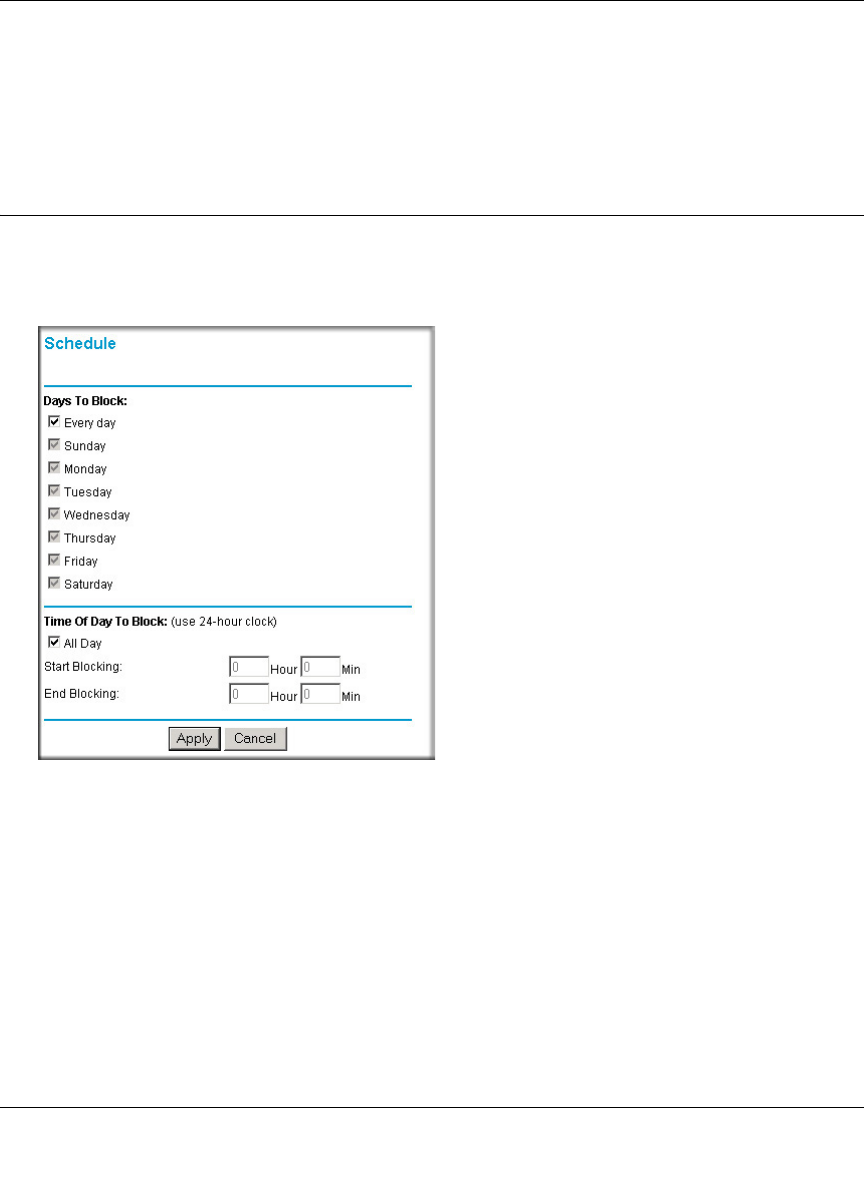
Reference Manual for the MR814 v3 Cable/DSL Wireless Router
Content Filtering 5-5
202-10039-01
Configuring Services Blocking by IP Address Range
Under “Filter Services For”, you can block the specified service for a single PC, a range of PCs
(having consecutive IP addresses), or all PCs on your network.
Scheduling When Blocking Will Be Enforced
The MR814 v3 router allows you to specify when blocking will be enforced. The Schedule menu
is shown below:
Figure 5-4: Schedule menu
• Use this schedule for blocking content. Check this box if you wish to enable a schedule for
Content Filtering. Click Apply.
• Days to Block. Select days to block by checking the appropriate boxes. Select Everyday to
check the boxes for all days. Click Apply.
• Time of Day to Block. Select a start and end time in 23:59 format. Select All day for 24 hour
blocking. Click Apply.
Be sure to select your Time Zone in the E-Mail menu.
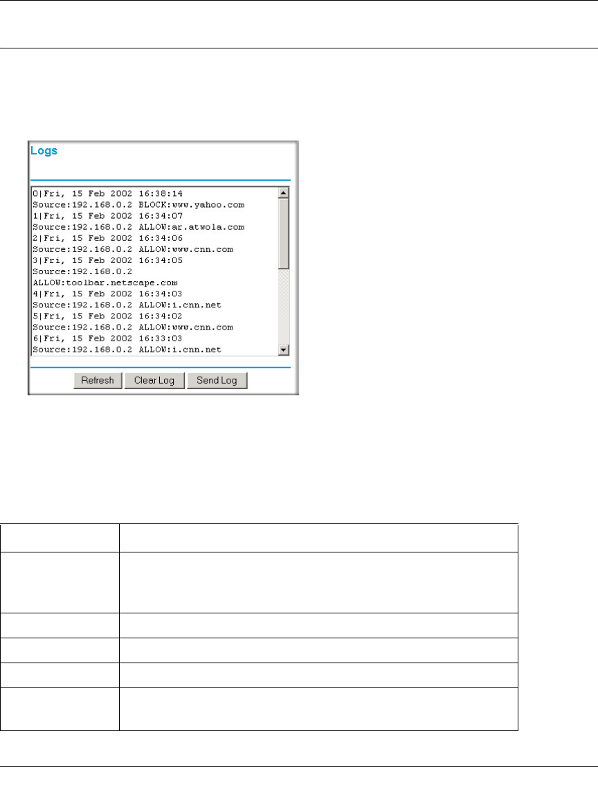
Reference Manual for the MR814 v3 Cable/DSL Wireless Router
5-6 Content Filtering
202-10039-01
Viewing Logs of Web Access or Attempted Web Access
The log is a detailed record of what Web sites you have accessed or attempted to access. Up to 128
entries are stored in the log. Log entries will only appear when keyword blocking is enabled, and
no log entries will be made for the Trusted User. An example is shown below:
Figure 5-5: Logs menu
Log entries are described in Table 5-1
Table 5-1. Log entry descriptions
Field Description
Number The index number of the content filter log entries. 128 entries
are available numbered from 0 to 127. The log will keep the
record of the latest 128 entries.
Date and Time The date and time the log entry was recorded.
Source IP The IP address of the initiating device for this log entry.
Action This field displays whether the access was blocked or allowed.
The name or IP address of the website or newsgroup visited or
attempted to access.
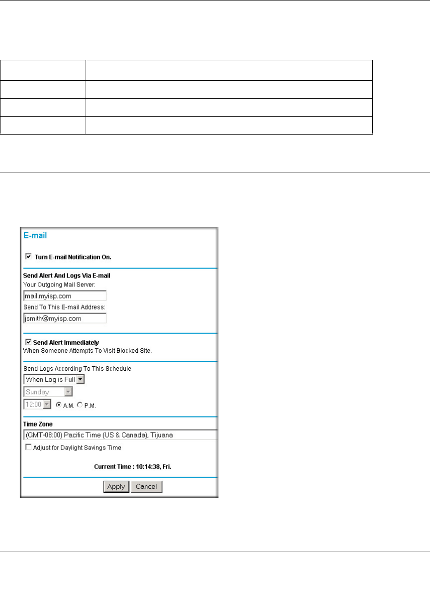
Reference Manual for the MR814 v3 Cable/DSL Wireless Router
Content Filtering 5-7
202-10039-01
Log action buttons are described in Table 5-2
Configuring E-Mail Alert and Web Access Log Notifications
In order to receive logs and alerts by E-mail, you must provide your E-mail information in the
E-Mail menu, shown below:
Figure 5-6: Email menu
Table 5-2. Log action buttons
Field Description
Refresh Click this button to refresh the log screen.
Clear Log Click this button to clear the log entries.
Send Log Click this button to email the log immediately.

Reference Manual for the MR814 v3 Cable/DSL Wireless Router
5-8 Content Filtering
202-10039-01
• Turn e-mail notification on
Check this box if you wish to receive e-mail logs and alerts from the router.
• Your outgoing mail server
Enter the name of your ISP’s outgoing (SMTP) mail server (such as mail.myISP.com). You
may be able to find this information in the configuration menu of your e-mail program. If you
leave this box blank, log and alert messages will not be sent via e-mail.
• Send to this e-mail address
Enter the e-mail address to which logs and alerts are sent. This e-mail address will also be used
as the From address. If you leave this box blank, log and alert messages will not be sent via
e-mail.
You can specify that logs are automatically sent to the specified e-mail address with these options:
• Send alert immediately
Check this box if you would like immediate notification of attempted access to a blocked site.
• Send logs according to this schedule
Specifies how often to send the logs: Hourly, Daily, Weekly, or When Full.
– Day for sending log
Specifies which day of the week to send the log. Relevant when the log is sent weekly or
daily.
– Time for sending log
Specifies the time of day to send the log. Relevant when the log is sent daily or weekly.
If the Weekly, Daily or Hourly option is selected and the log fills up before the specified
period, the log is automatically e-mailed to the specified e-mail address. After the log is sent,
the log is cleared from the router’s memory. If the router cannot e-mail the log file, the log
buffer may fill up. In this case, the router overwrites the log and discards its contents.
The MR814 v3 router uses the Network Time Protocol (NTP) to obtain the current time and date
from one of several Network Time Servers on the Internet. In order to localize the time for your
log entries, you must specify your Time Zone:
•Time Zone
Select your local time zone. This setting will be used for the blocking schedule and for
time-stamping log entries.
• Daylight Savings Time
Check this box if your time zone is currently under daylight savings time.
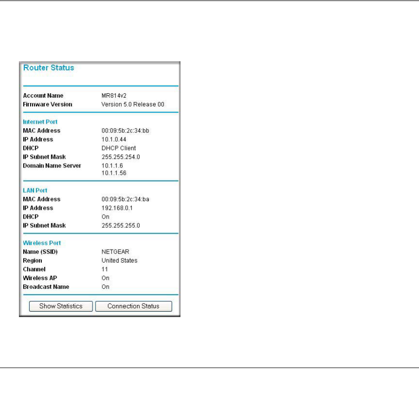
Maintenance 6-1
202-10039-01
Chapter 6
Maintenance
This chapter describes how to use the maintenance features of your MR814 v3 Cable/DSL
Wireless Router. These features can be found by clicking on the Maintenance heading in the Main
Menu of the browser interface.
Viewing Router Status Information
The Router Status menu provides a limited amount of status and usage information. From the
Main Menu of the browser interface, click on Maintenance, then select System Status to view the
System Status screen, shown below.
Figure 6-1: Router Status screen

Reference Manual for the MR814 v3 Cable/DSL Wireless Router
6-2 Maintenance
202-10039-01
This screen shows the following parameters:
Table 6-1. Router Status Fields
Field Description
Account Name This field displays the Host Name assigned to the router.
Firmware Version This field displays the router firmware version.
Internet Port These parameters apply to the Internet (WAN) port of the router.
MAC Address This field displays the Media Access Control address being used by the
Internet (WAN) port of the router.
IP Address This field displays the IP address being used by the Internet (WAN) port
of the router. If no address is shown, the router cannot connect to the
Internet.
IP Subnet Mask This field displays the IP Subnet Mask being used by the Internet (WAN)
port of the router.
DHCP If set to None, the router is configured to use a fixed IP address on the
WAN.
If set to Client, the router is configured to obtain an IP address
dynamically from the ISP.
LAN Port These parameters apply to the Local (WAN) port of the router.
MAC Address This field displays the Media Access Control address being used by the
LAN port of the router.
IP Address This field displays the IP address being used by the Local (LAN) port of
the router. The default is 192.168.0.1
IP Subnet Mask This field displays the IP Subnet Mask being used by the Local (LAN)
port of the router. The default is 255.255.255.0
DHCP Identifies if the router’s built-in DHCP server is active for the LAN
attached devices.
Wireless Port These parameters apply to the Wireless port of the router.
MAC Address This field displays the Media Access Control address being used by the
Wireless port of the router.
Name (SSID) This field displays the wireless network name (SSID) being used by the
wireless port of the router. The default is Wireless.
Region This field displays the geographic region where the router being used. It
may be illegal to use the wireless features of the router in some parts of
the world.
Channel Identifies if the channel the wireless port is using. See “Wireless
Channels” on page D-2 for the frequencies used on each channel.
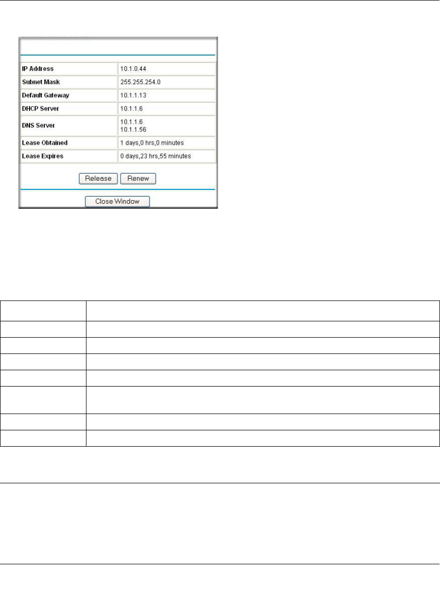
Reference Manual for the MR814 v3 Cable/DSL Wireless Router
Maintenance 6-3
202-10039-01
Click on the “Show Connection Status” button to display the connection status, as shown below.
Figure 6-2: Connection Status screen
This screen shows the following statistics:.
Table 6-2: Connection Status Items
Item Description
IP Address The WAN (Internet) IP Address assigned to the router.
Subnet Mask The WAN (Internet) Subnet Mask assigned to the router.
Default Gateway The WAN (Internet) default gateway the router communicates with.
DHCP Server The IP address of the DHCP server which provided the IP configuration addresses.
DNS Server The IP address of the DNS server which provides network name to IP address
translation.
Lease Obtained When the DHCP lease was obtained.
Lease Expires When the DHCP lease was expires.
Release Click the Release button to release the DHCP lease.
Renew Click the Renew button to renew the DHCP lease.