Netgear orporated MR814V3 Wireless Router User Manual FullManual

Netgear Incorporated Wireless Router FullManual

Contents

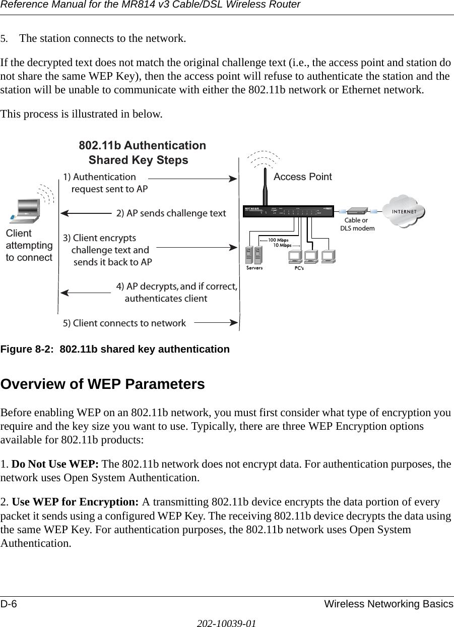
Users Manual Part 2 Revised

Reference Manual for the MR814 v3 Cable/DSL Wireless Router 6-4 Maintenance202-10039-01Click on the “Show Statistics” button to display router usage statistics, as shown below.Figure 6-3:  Router Statistics screenThis screen shows the following statistics:Table 6-3: Router Statistics ItemsItem DescriptionPort The statistics for the WAN (Internet) and LAN (local) ports. For each port, the screen displays:Status The link status of the port.TxPkts The number of packets transmitted on this port since reset or manual clear.RxPkts The number of packets received on this port since reset or manual clear.Collisions The number of collisions on this port since reset or manual clear.Tx B/s The current transmission (outbound) bandwidth used on the WAN and LAN ports.Rx B/s The current reception (inbound) bandwidth used on the WAN and LAN ports.Up Time The amount of time since the router was last restarted.Up Time The time elapsed since this port acquired the link.Poll Interval Specifies the intervals at which the statistics are updated in this window. Click on Stop to freeze the display.Set Interval Enter a time and click the button to set the polling frequency.Stop Click the Stop button to freeze the polling information.
Reference Manual for the MR814 v3 Cable/DSL Wireless Router Maintenance 6-5202-10039-01Viewing a List of Attached DevicesThe Attached Devices menu contains a table of all IP devices that the router has discovered on the local network. From the Main Menu of the browser interface, under the Maintenance heading, select Attached Devices to view the table, shown below.Figure 6-4:  Attached Devices menuFor each device, the table shows the IP address, NetBIOS Host Name (if available), and Ethernet MAC address. Note that if the router is rebooted, the table data is lost until the router rediscovers the devices. To force the router to look for attached devices, click the Refresh button.Configuration File ManagementThe configuration settings of the MR814 v3 router are stored within the router in a configuration file. This file can be saved (backed up) to a user’s PC, retrieved (restored) from the user’s PC, or cleared to factory default settings.
Reference Manual for the MR814 v3 Cable/DSL Wireless Router 6-6 Maintenance202-10039-01From the Main Menu of the browser interface, under the Maintenance heading, select the Settings Backup heading to bring up the menu shown below. Figure 6-5:  Settings Backup menuThree options are available, and are described in the following sections.Restoring and Backing Up the ConfigurationThe Restore and Backup options in the Settings Backup menu allow you to save and retrieve a file containing your router’s configuration settings.To save your settings, select the Backup tab. Click the Backup button. Your browser will extract the configuration file from the router and will prompt you for a location on your PC to store the file. You can give the file a meaningful name at this time, such as pacbell.cfg.To restore your settings from a saved configuration file, enter the full path to the file on your PC or click the Browse button to browse to the file. When you have located it, click the Restore button to send the file to the router. The router will then reboot automatically.
Reference Manual for the MR814 v3 Cable/DSL Wireless Router Maintenance 6-7202-10039-01Erasing the ConfigurationIt is sometimes desirable to restore the router to a known blank condition. This can be done by using the Erase function, which will restore all factory settings. After an erase, the router's password will be password, the LAN IP address will be 192.168.0.1, and the router's DHCP client will be enabled.To erase the configuration, click the Erase button.To restore the factory default configuration settings without knowing the login password or IP address, you must use the Default Reset button on the rear panel of the router. See “Restoring the Default Configuration and Password” on page 8-7.Upgrading the Router SoftwareThe routing software of the MR814 v3 router is stored in FLASH memory, and can be upgraded as new software is released by NETGEAR. Upgrade files can be downloaded from Netgear's Web site. If the upgrade file is compressed (.ZIP file), you must first extract the binary (.BIN) file before sending it to the router. The upgrade file can be sent to the router using your browser. Note: The Web browser used to upload new firmware into the MR814 v3 router must support HTTP uploads. NETGEAR recommends using Microsoft Internet Explorer or Netscape Navigator 3.0 or above. Note: Before upgrading the router software, use the router backup utility to save your configuration settings. Any router upgrade will revert the router settings back to the factory defaults. After completing the upgrade, you can restore your settings from the backup.
Reference Manual for the MR814 v3 Cable/DSL Wireless Router 6-8 Maintenance202-10039-01From the Main Menu of the browser interface, under the Maintenance heading, select the Router Upgrade heading to display the menu shown below. Figure 6-6:  Router Upgrade menuTo upload new firmware:1. Download and unzip the new software file from NETGEAR. 2. In the Router Upgrade menu, click the Browse button and browse to the location of the binary (.BIN) upgrade file3. Click Upload.Note: When uploading software to the MR814 v3 router, it is important not to interrupt the Web browser by closing the window, clicking a link, or loading a new page. If the browser is interrupted, it may corrupt the software. When the upload is complete, your router will automatically restart. The upgrade process will typically take about one minute.In some cases, you may need to reconfigure the router after upgrading.Changing the Administrator PasswordNote: Before changing the router password, use the router backup utility to save your configuration settings. If after changing the password, you forget the new password you assigned, you will have to reset the router back to the factory defaults to be able to log in using the default password of password. This means you will have to restore all the router configuration settings. If you ever have to reset the router back to the factory defaults, you can restore your settings from the backup.
Reference Manual for the MR814 v3 Cable/DSL Wireless Router Maintenance 6-9202-10039-01The default password for the router’s Web Configuration Manager is password. Netgear recommends that you change this password to a more secure password. From the Main Menu of the browser interface, under the Maintenance heading, select Set Password to bring up the menu shown below.Figure 6-7:  Set Password menuTo change the password, first enter the old password, and then enter the new password twice. Click Apply.
Reference Manual for the MR814 v3 Cable/DSL Wireless Router 6-10 Maintenance202-10039-01
Advanced Configuration of the Router 7-1202-10039-01Chapter 7 Advanced Configuration of the Router This chapter describes how to configure the advanced features of your MR814 v3 Cable/DSL Wireless Router. These features can be found under the Advanced heading in the Main Menu of the browser interface.Configuring for Port Forwarding to Local ServersAlthough the router causes your entire local network to appear as a single machine to the Internet, you can make a local server (for example, a web server or game server) visible and available to the Internet. This is done using the Port Forwarding menu. From the Main Menu of the browser interface, under Advanced, click on Port Forwarding to view the port forwarding menu, shown below.Figure 7-1:  Port Forwarding Menu.Note: If you are unfamiliar with networking and routing, refer to Appendix B, “Network, Routing, Firewall, and Basics,” to become more familiar with the terms and procedures used in this manual.
Reference Manual for the MR814 v3 Cable/DSL Wireless Router 7-2 Advanced Configuration of the Router202-10039-01Use the Port Forwarding menu to configure the router to forward incoming protocols to computers on your local network. In addition to servers for specific applications, you can also specify a Default DMZ Server to which all other incoming protocols are forwarded. The DMZ Server is configured in the Security Menu.Before starting, you'll need to determine which type of service, application or game you'll provide and the IP address of the computer that will provide each service. Be sure the computer’s IP address never changes. To configure port forwarding to a local server:1. From the Service & Game box, select the service or game that you will host on your network. If the service does not appear in the list, refer to the following section, “Adding a Custom Service”.2. Enter the IP address of the local server in the corresponding Server IP Address box.3. Click the Add button.Adding a Custom ServiceTo define a service, game or application that does not appear in the Services & Games list, you must determine what port numbers are used by the service. For this information, you may need to contact the manufacturer of the program that you wish to use. When you have the port number information, follow these steps:1. Click the Add Custom Service button.2. Enter the first port number in an unused Start Port box.3. To forward only one port, enter it again in the End Port box. To specify a range of ports, enter the last port to be forwarded in the End Port box.4. Enter the IP address of the local server in the corresponding Server IP Address box.5. Type a name for the service.6. Click Apply at the bottom of the menu.Note: To assure that the same computer always has the same IP address, use the reserved IP address feature of your MR814 v3 router. See “Using Address Reservation“ on page 7-8 for instructions on how to use reserved IP addresses.
Reference Manual for the MR814 v3 Cable/DSL Wireless Router Advanced Configuration of the Router 7-3202-10039-01Editing or Deleting a Port Forwarding EntryTo edit or delete a Port Forwarding entry, follow these steps.1. In the table, select the button next to the service name.2. Click Edit or Delete.Local Web and FTP Server ExampleIf a local PC with a private IP address of 192.168.0.33 acts as a Web and FTP server, configure the Ports menu to forward HTTP (port 80) and FTP (port 21) to local address 192.168.0.33 In order for a remote user to access this server from the Internet, the remote user must know the IP address that has been assigned by your ISP. If this address is 172.16.1.23, for example, an Internet user can access your Web server by directing the browser to http://172.16.1.23. The assigned IP address can be found in the Maintenance Status Menu, where it is shown as the WAN IP Address.Some considerations for this application are:• If your account’s IP address is assigned dynamically by your ISP, the IP address may change periodically as the DHCP lease expires.• If the IP address of the local PC is assigned by DHCP, it may change when the PC is rebooted. To avoid this, you can manually configure the PC to use a fixed address.• Local PCs must access the local server using the PCs’ local LAN address (192.168.0.33 in this example). Attempts by local PCs to access the server using the external IP address (172.16.1.23 in this example) will fail.Multiple Computers for Half Life, KALI or Quake III ExampleTo set up an additional computer to play Half Life, KALI or Quake III: 1. Click the button of an unused port in the table. 2. Select the game again from the Services/Games list. 3. Change the beginning port number in the Start Port box.  For these games, use the supplied number in the default listing and add +1 for each additional computer. For example, if you've already configured one computer to play Hexen II (using port 26900), the second computer's port number would be 26901, and the third computer would be 26902.
Reference Manual for the MR814 v3 Cable/DSL Wireless Router 7-4 Advanced Configuration of the Router202-10039-014. Type the same port number in the End Port box that you typed in the Start Port box. 5. Type the IP address of the additional computer in the Server IP Address box. 6. Click Apply. Some online games and videoconferencing applications are incompatible with NAT. The MR814 v3 router is programmed to recognize some of these applications and to work properly with them, but there are other applications that may not function well. In some cases, one local PC can run the application properly if that PC’s IP address is entered as the default in the PORTS Menu. If one local PC acts as a game or videoconferencing host, enter its IP address as the default.Configuring the WAN Setup OptionsThe WAN Setup options let you configure a DMZ server, change the MTU size and enable the router to respond to a Ping on the WAN port. These options are discussed below.Setting Up a Default DMZ ServerThe default DMZ server feature is helpful when using some online games and videoconferencing applications that are incompatible with NAT. The router is programmed to recognize some of these applications and to work properly with them, but there are other applications that may not function well. In some cases, one local PC can run the application properly if that PC’s IP address is entered as the default DMZ server.Incoming traffic from the Internet is normally discarded by the router unless the traffic is a response to one of your local computers or a service that you have configured in the Ports menu. Instead of discarding this traffic, you can have it forwarded to one computer on your network. This computer is called the Default DMZ Server.Note: DMZ servers pose a security risk. A computer designated as the default DMZ server loses much of the protection of the firewall, and is exposed to exploits from the Internet. If compromised, the DMZ server can be used to attack your network.
Reference Manual for the MR814 v3 Cable/DSL Wireless Router Advanced Configuration of the Router 7-5202-10039-01The WAN Setup menu, shown below lets you configure a Default DMZ Server. Figure 7-2:  WAN Setup menu.To assign a computer or server to be a Default DMZ server, follow these steps: 1. Click WAN Setup link on the Advanced section of the main menu. 2. Type the IP address for that server. To remove the default DMZ server, replace the IP address numbers with all zeros.3. Click Apply.Respond to Ping on Internet WAN Port If you want the router to respond to a 'ping' from the Internet, click the ‘Respond to Ping on Internet WAN Port’ check box. This should only be used as a diagnostic tool, since it allows your router to be discovered. Don't check this box unless you have a specific reason to do so.Setting the MTU SizeThe default MTU size is usually fine. The normal MTU (Maximum Transmit Unit) value for most Ethernet networks is 1500 Bytes. For some ISPs, particularly some using PPPoE, you may need to reduce the MTU. This should not be done unless you are sure it is necessary by your ISP. Any packets sent through the router that are larger than the configured MTU size will be repackaged into smaller packets to meet the MTU requirement. To change the MTU size:1. Under MTU Size, enter a new size between 64 and 1500.2. Click Apply to save the new configuration.
Reference Manual for the MR814 v3 Cable/DSL Wireless Router 7-6 Advanced Configuration of the Router202-10039-01Using the LAN IP Setup OptionsThe second feature category under the Advanced heading is LAN IP Setup. This menu allows configuration of LAN IP services such as DHCP and RIP. From the Main Menu of the browser interface, under Advanced, click on LAN IP Setup to view the LAN IP Setup menu, shown below.Figure 7-3:  LAN IP Setup MenuConfiguring LAN TCP/IP Setup ParametersThe router is shipped preconfigured to use private IP addresses on the LAN side, and to act.as a DHCP server. The router’s default LAN IP configuration is:• LAN IP addresses—192.168.0.1• Subnet mask—255.255.255.0
Reference Manual for the MR814 v3 Cable/DSL Wireless Router Advanced Configuration of the Router 7-7202-10039-01These addresses are part of the IETF-designated private address range for use in private networks, and should be suitable in most applications. If your network has a requirement to use a different IP addressing scheme, you can make those changes in this menu.The LAN IP parameters are:• IP Address This is the LAN IP address of the router.• IP Subnet Mask This is the LAN Subnet Mask of the router. Combined with the IP address, the IP Subnet Mask allows a device to know which other addresses are local to it, and which must be reached through a gateway or router.• RIP Direction RIP (Router Information Protocol) allows a router to exchange routing information with other routers. The RIP Direction selection controls how the router sends and receives RIP packets. Both is the default. — When set to Both or Out Only, the router will broadcast its routing table periodically. — When set to Both or In Only, it will incorporate the RIP information that it receives. — When set to None, it will not send any RIP packets and will ignore any RIP packets received. • RIP Version This controls the format and the broadcasting method of the RIP packets that the router sends. (It recognizes both formats when receiving.) By default, this is set for RIP-1. — RIP-1 is universally supported. RIP-1 is probably adequate for most networks, unless you have an unusual network setup. — RIP-2 carries more information. RIP-2B uses subnet broadcasting.Note: If you change the LAN IP address of the router while connected through the browser, you will be disconnected. You must then open a new connection to the new IP address and log in again.
Reference Manual for the MR814 v3 Cable/DSL Wireless Router 7-8 Advanced Configuration of the Router202-10039-01Using the Router as a DHCP serverBy default, the router will function as a DHCP (Dynamic Host Configuration Protocol) server, allowing it to assign IP, DNS server, and default gateway addresses to all computers connected to the router's LAN. The assigned default gateway address is the LAN address of the router. IP addresses will be assigned to the attached PCs from a pool of addresses specified in this menu. Each pool address is tested before it is assigned to avoid duplicate addresses on the LAN.For most applications, the default DHCP and TCP/IP settings of the router are satisfactory. See “IP Configuration by DHCP” on page B-10 for an explanation of DHCP and information about how to assign IP addresses for your network. If another device on your network will be the DHCP server, or if you will manually configure the network settings of all of your computers, clear the ‘Use router as DHCP server’ check box. Otherwise, leave it checked. Specify the pool of IP addresses to be assigned by setting the Starting IP Address and Ending IP Address. These addresses should be part of the same IP address subnet as the router’s LAN IP address. Using the default addressing scheme, you should define a range between 192.168.0.2 and 192.168.0.253, although you may wish to save part of the range for devices with fixed addresses.The router will deliver the following parameters to any LAN device that requests DHCP:• An IP Address from the range you have defined• Subnet Mask• Gateway IP Address (the router’s LAN IP address)• Primary DNS Server (if you entered a Primary DNS address in the Basic Settings menu; otherwise, the router’s LAN IP address)• Secondary DNS Server (if you entered a Secondary DNS address in the Basic Settings menuUsing Address ReservationWhen you specify a reserved IP address for a PC on the LAN, that PC will always receive the same IP address each time it access the router’s DHCP server. Reserved IP addresses should be assigned to servers that require permanent IP settings. To reserve an IP address: 1. Click the Add button.
Reference Manual for the MR814 v3 Cable/DSL Wireless Router Advanced Configuration of the Router 7-9202-10039-012. In the IP Address box, type the IP address to assign to the PC or server. (choose an IP address from the router’s LAN subnet, such as 192.168.0.X) 3. Type the MAC Address of the PC or server.  (Tip: If the PC is already present on your network, you can copy its MAC address from the Attached Devices menu and paste it here.) 4. Click Apply to enter the reserved address into the table. Note: The reserved address will not be assigned until the next time the PC contacts the router's DHCP server. Reboot the PC or access its IP configuration and force a DHCP release and renew. To edit or delete a reserved address entry: 1. Click the button next to the reserved address you want to edit or delete. 2. Click Edit or Delete.Using a Dynamic DNS ServiceIf your network has a permanently assigned IP address, you can register a domain name and have that name linked with your IP address by public Domain Name Servers (DNS). However, if your Internet account uses a dynamically assigned IP address, you will not know in advance what your IP address will be, and the address can change frequently. In this case, you can use a commercial dynamic DNS service, who will allow you to register your domain to their IP address, and will forward traffic directed at your domain to your frequently-changing IP address.The router contains a client that can connect to many popular dynamic DNS services. You can select one of these services and obtain an account with them. Then, whenever your ISP-assigned IP address changes, your router will automatically contact your dynamic DNS service provider, log in to your account, and register your new IP address.From the Main Menu of the browser interface, under Advanced, click on Dynamic DNS. To configure Dynamic DNS:1. Register for an account with one of the dynamic DNS service providers whose names appear in the ‘Select Service Provider’ box. For example, for dyndns.org, go to www.dyndns.org.Note: If your ISP assigns a private WAN IP address (such as 192.168.x.x or 10.x.x.x), the dynamic DNS service will not work because private addresses will not be routed on the Internet.
Reference Manual for the MR814 v3 Cable/DSL Wireless Router 7-10 Advanced Configuration of the Router202-10039-012. Select the Use a dynamic DNS service check box. 3. Select the name of your dynamic DNS Service Provider. 4. Type the Host Name (or domain name) that your dynamic DNS service provider gave you.5. Type the User Name for your dynamic DNS account. 6. Type the Password (or key) for your dynamic DNS account. 7. If your dynamic DNS provider allows the use of wildcards in resolving your URL, you may select the Use wildcards check box to activate this feature.  For example, the wildcard feature will cause *.yourhost.dyndns.org to be aliased to the same IP address as yourhost.dyndns.org8. Click Apply to save your configuration.Configuring Static RoutesStatic Routes provide additional routing information to your router. Under normal circumstances, the router has adequate routing information after it has been configured for Internet access, and you do not need to configure additional static routes. You must configure static routes only for unusual cases such as multiple routers or multiple IP subnets located on your network.From the Main Menu of the browser interface, under Advanced, click on Static Routes to view the Static Route menu, shown below. Figure 7-4. Static Route Summary TableTo add or edit a Static Route:
Reference Manual for the MR814 v3 Cable/DSL Wireless Router Advanced Configuration of the Router 7-11202-10039-011. Click the Add button to open the Add/Edit Menu, shown below.Figure 7-5. Static Route Entry and Edit Menu2. Type a route name for this static route in the Route Name box under the table. (This is for identification purpose only.) 3. Select Private if you want to limit access to the LAN only. The static route will not be reported in RIP. 4. Select Active to make this route effective. 5. Type the Destination IP Address of the final destination. 6. Type the IP Subnet Mask for this destination. If the destination is a single host, type 255.255.255.255. 7. Type the Gateway IP Address, which must be a router on the same LAN segment as the router. 8. Type a number between 1 and 15 as the Metric value.  This represents the number of routers between your network and the destination. Usually, a setting of 2 or 3 works, but if this is a direct connection, set it to 1. 9. Click Apply to have the static route entered into the table. As an example of when a static route is needed, consider the following case:• Your primary Internet access is through a cable modem to an ISP.• You have an ISDN router on your home network for connecting to the company where you are employed. This router’s address on your LAN is 192.168.0.100.• Your company’s network is 134.177.0.0.
Reference Manual for the MR814 v3 Cable/DSL Wireless Router 7-12 Advanced Configuration of the Router202-10039-01When you first configured your router, two implicit static routes were created. A default route was created with your ISP as the gateway, and a second static route was created to your local network for all 192.168.0.x addresses. With this configuration, if you attempt to access a device on the 134.177.0.0 network, your router will forward your request to the ISP. The ISP forwards your request to the company where you are employed, and the request will likely be denied by the company’s firewall.In this case you must define a static route, telling your router that 134.177.0.0 should be accessed through the ISDN router at 192.168.0.100. The static route would look like Figure 7-5.In this example:• The Destination IP Address and IP Subnet Mask fields specify that this static route applies to all 134.177.x.x addresses. • The Gateway IP Address fields specifies that all traffic for these addresses should be forwarded to the ISDN router at 192.168.0.100. • A Metric value of 1 will work since the ISDN router is on the LAN. • Private is selected only as a precautionary security measure in case RIP is activated.Enabling Remote Management AccessUsing the Remote Management page, you can allow a user or users on the Internet to configure, upgrade and check the status of your MR814 v3 router.To configure your router for Remote Management:1. Select the Turn Remote Management On check box.2. Specify what external addresses will be allowed to access the router’s remote management.  Note: For enhanced security, restrict access to as few external IP addresses as practical.a. To allow access from any IP address on the Internet, select Everyone. Note: Be sure to change the router's default configuration password to a very secure password. The ideal password should contain no dictionary words from any language, and should be a mixture of letters (both upper and lower case), numbers, and symbols. Your password can be up to 30 characters.
Reference Manual for the MR814 v3 Cable/DSL Wireless Router Advanced Configuration of the Router 7-13202-10039-01b. To allow access from a range of IP addresses on the Internet, select IP address range. Enter a beginning and ending IP address to define the allowed range. c. To allow access from a single IP address on the Internet, select Only this PC. Enter the IP address that will be allowed access. 3. Specify the Port Number that will be used for accessing the management interface.Web browser access normally uses the standard HTTP service port 80. For greater security, change the remote management web interface to a custom port by entering that number in the box provided. Choose a number between 1024 and 65535, but do not use the number of any common service port. The default is 8080, which is a common alternate for HTTP.4. Click Apply to have your changes take effect.Note: When accessing your router from the Internet, you will type your router's WAN IP address into your browser's Address (in IE) or Location (in Netscape) box, followed by a colon (:) and the custom port number. For example, if your external address is 134.177.0.123 and you use port number 8080, you must enter http://134.177.0.123:8080 in your browser.Using Universal Plug and Play (UPnP)Universal Plug and Play (UPnP) helps devices, such as Internet appliances and computers, access the network and connect to other devices as needed. UPnP devices can automatically discover the services from other registered UPnP devices on the network.Figure 7-6. UPnP Menu
Reference Manual for the MR814 v3 Cable/DSL Wireless Router 7-14 Advanced Configuration of the Router202-10039-01From the Main Menu of the browser interface, under Advanced, click on UPnP. Set up UPnP according to the guidelines below. Turn UPnP On: UPnP can be enabled or disabled for automatic device configuration. The default setting for UPnP is disabled. If disabled, the router will not allow any device to automatically control the resources, such as port forwarding (mapping), of the router. Note: If you use applications such as multi-player gaming, peer-to-peer connections, real time communications such as instant messaging, or remote assistance (a feature in Windows XP), you should enable UPnP.Advertisement Period: The Advertisement Period is how often the router will broadcast its UPnP information. This value can range from 1 to 1440 minutes. The default period is 30 minutes. Shorter durations will ensure that control points have current device status at the expense of additional network traffic. Longer durations may compromise the freshness of the device status but can significantly reduce network traffic.Advertisement Time To Live: The time to live for the advertisement is measured in hops (steps) for each UPnP packet sent. The time to live hop count is the number of steps a broadcast packet is allowed to propagate for each UPnP advertisement before it disappears. The number of hops can range from 1 to 255. The default value for the advertisement time to live is 4 hops, which should be fine for most home networks. If you notice that some devices are not being updated or reached correctly, then it may be necessary to increase this value a little.UPnP Portmap Table: The UPnP Portmap Table displays the IP address of each UPnP device that is currently accessing the router and which ports (Internal and External) that device has opened. The UPnP Portmap Table also displays what type of port is opened and if that port is still active for each IP address.
Troubleshooting 8-1202-10039-01Chapter 8 TroubleshootingThis chapter gives information about troubleshooting your MR814 v3 Cable/DSL Wireless Router. After each problem description, instructions are provided to help you diagnose and solve the problem.Basic FunctioningAfter you turn on power to the router, the following sequence of events should occur:1. When power is first applied, verify that the Power light  is on.2. After approximately 10 seconds, verify that:a. The power light is solid green.b. The LAN port lights are lit for any local ports that are connected.c. The Internet port light is lit.If a port’s light is lit, a link has been established to the connected device. If a LAN port is connected to a 100 Mbps device, verify that the port’s light is green. If the port is 10 Mbps, the light will be amber.If any of these conditions does not occur, refer to the appropriate following section.Power Light Not OnIf the Power and other lights are off when your router is turned on:• Make sure that the power cord is properly connected to your router and that the power supply adapter is properly connected to a functioning power outlet. • Check that you are using the 12 V DC 1A power adapter supplied by NETGEAR for this product.If the error persists, you have a hardware problem and should contact technical support.
Reference Manual for the MR814 v3 Cable/DSL Wireless Router 8-2 Troubleshooting202-10039-01Lights Never Turn Off When the router is turned on, the lights turns on for about 10 seconds and then turn off. If all the lights stay on, there is a fault within the router.If all lights are still on one minute after power up:• Cycle the power to see if the router recovers.• Clear the router’s configuration to factory defaults. This will set the router’s IP address to 192.168.0.1. This procedure is explained in “Restoring the Default Configuration and Password” on page 8-7.If the error persists, you might have a hardware problem and should contact technical support.LAN or WAN Port Lights Not OnIf either the LAN lights or Internet light do not light when the Ethernet connection is made, check the following:• Make sure that the Ethernet cable connections are secure at the router and at the hub or workstation.• Make sure that power is turned on to the connected hub or workstation.• Be sure you are using the correct cable:— When connecting the router’s Internet port to a cable or DSL modem, use the cable that was supplied with the cable or DSL modem. This cable could be a standard straight-through Ethernet cable or an Ethernet crossover cable.
Reference Manual for the MR814 v3 Cable/DSL Wireless Router Troubleshooting 8-3202-10039-01Troubleshooting the Web Configuration InterfaceIf you are unable to access the router’s web Configuration interface from a computer on your local network, check the following:• Check the Ethernet connection between the computer and the router as described in the previous section.• Make sure your computer’s IP address is on the same subnet as the router. If you are using the recommended addressing scheme, your computer’s address should be in the range of 192.168.0.2 to 192.168.0.254. Refer to “Verifying TCP/IP Properties” on page C-8 or “Verifying TCP/IP Properties for Macintosh Computers” on page C-19 to find your computer’s IP address. Follow the instructions in Appendix C to configure your computer.Note: If your computer’s IP address is shown as 169.254.x.x: Recent versions of Windows and MacOS will generate and assign an IP address if the computer cannot reach a DHCP server. These auto-generated addresses are in the range of 169.254.x.x. If your IP address is in this range, check the connection from the computer to the router and reboot your computer.• If your router’s IP address has been changed and you don’t know the current IP address, clear the router’s configuration to factory defaults. This will set the router’s IP address to 192.168.0.1. This procedure is explained in “Restoring the Default Configuration and Password” on page 8-7.• Make sure your browser has Java, JavaScript, or ActiveX enabled. If you are using Internet Explorer, click Refresh to be sure the Java applet is loaded.• Try quitting the browser and launching it again.• Make sure you are using the correct login information. The factory default login name is admin and the password is password. Make sure that CAPS LOCK is off when entering this information.If the router does not save changes you have made in the web Configuration Interface, check the following:• When entering configuration settings, be sure to click the APPLY button before moving to another menu or tab, or your changes are lost. • Click the Refresh or Reload button in the web browser. The changes may have occurred, but the web browser may be caching the old configuration.
Reference Manual for the MR814 v3 Cable/DSL Wireless Router 8-4 Troubleshooting202-10039-01Troubleshooting the ISP ConnectionIf your router is unable to access the Internet, you should first determine whether the router is able to obtain a WAN IP address from the ISP. Unless you have been assigned a static IP address, your router must request an IP address from the ISP. You can determine whether the request was successful using the web Configuration Manager.To check the WAN IP address: 1. Launch your browser and select an external site such as www.netgear.com2. Access the Main Menu of the router’s configuration at http://www.routerlogin.net. 3. Under the Maintenance heading, select Router Status4. Check that an IP address is shown for the WAN Port If 0.0.0.0 is shown, your router has not obtained an IP address from your ISP.If your router is unable to obtain an IP address from the ISP, you may need to force your cable or DSL modem to recognize your new router by performing the following procedure:1. Turn off power to the cable or DSL modem. 2. Turn off power to your router. 3. Wait five minutes and reapply power to the cable or DSL modem. 4. When the modem’s lights indicate that it has reacquired sync with the ISP, reapply power to your router.5. Then restart your computer.If your router is still unable to obtain an IP address from the ISP, the problem may be one of the following:• Your ISP may require a login program. Ask your ISP whether they require PPP over Ethernet (PPPoE) or some other type of login.• If your ISP requires a login, you may have incorrectly set the login name and password.• Your ISP may check for your computer's host name. Assign the computer Host Name of your ISP account as the Account Name in the Basic Settings menu.• Your ISP only allows one Ethernet MAC address to connect to Internet, and may check for your computer’s MAC address. In this case:
Reference Manual for the MR814 v3 Cable/DSL Wireless Router Troubleshooting 8-5202-10039-01Inform your ISP that you have bought a new network device, and ask them to use the router’s MAC address.ORConfigure your router to spoof your computer’s MAC address. This can be done in the Basic Settings menu. Refer to “How to Bypass the Configuration Assistant” on page 3-12.If your router can obtain an IP address, but your computer is unable to load any web pages from the Internet:• Your computer may not recognize any DNS server addresses. A DNS server is a host on the Internet that translates Internet names (such as www addresses) to numeric IP addresses. Typically your ISP will provide the addresses of one or two DNS servers for your use. If you entered a DNS address during the router’s configuration, reboot your computer and verify the DNS address as described in “Install or Verify Windows Networking Components” on page C-9. Alternatively, you may configure your computer manually with DNS addresses, as explained in your operating system documentation.• Your computer may not have the router configured as its TCP/IP gateway.If your computer obtains its information from the router by DHCP, reboot the computer and verify the gateway address as described in “Install or Verify Windows Networking Components” on page C-9.Troubleshooting a TCP/IP Network Using a Ping UtilityMost TCP/IP terminal devices and routers contain a ping utility that sends an echo request packet to the designated device. The device then responds with an echo reply. Troubleshooting a TCP/IP network is made very easy by using the ping utility in your computer or workstation.Testing the LAN Path to Your RouterYou can ping the router from your computer to verify that the LAN path to your router is set up correctly.To ping the router from a PC running Windows 95 or later:1. From the Windows toolbar, click on the Start button and select Run.2. In the field provided, type Ping followed by the IP address of the router, as in this example:ping 192.168.0.1
Reference Manual for the MR814 v3 Cable/DSL Wireless Router 8-6 Troubleshooting202-10039-013. Click on OK.You should see a message like this one:Pinging <IP address> with 32 bytes of dataIf the path is working, you see this message:Reply from < IP address >: bytes=32 time=NN ms TTL=xxxIf the path is not working, you see this message:Request timed outIf the path is not functioning correctly, you could have one of the following problems:• Wrong physical connections— Make sure the LAN port LED is on. If the LED is off, follow the instructions in “LAN or WAN Port Lights Not On” on page 8-2.— Check that the corresponding Link LEDs are on for your network interface card and for the hub ports (if any) that are connected to your workstation and router.• Wrong network configuration— Verify that the Ethernet card driver software and TCP/IP software are both installed and configured on your computer or workstation.— Verify that the IP address for your router and your workstation are correct and that the addresses are on the same subnet.Testing the Path from Your Computer to a Remote DeviceAfter verifying that the LAN path works correctly, test the path from your computer to a remote device. From the Windows run menu, type:PING -n 10 <IP address>where <IP address> is the IP address of a remote device such as your ISP’s DNS server.If the path is functioning correctly, replies as in the previous section are displayed. If you do not receive replies:— Check that your computer has the IP address of your router listed as the default gateway. If the IP configuration of your computer is assigned by DHCP, this information will not be visible in your computer’s Network Control Panel. Verify that the IP address of the router is listed as the default gateway as described in “Install or Verify Windows Networking Components” on page C-9.
Reference Manual for the MR814 v3 Cable/DSL Wireless Router Troubleshooting 8-7202-10039-01— Check to see that the network address of your computer (the portion of the IP address specified by the netmask) is different from the network address of the remote device.— Check that your cable or DSL modem is connected and functioning.— If your ISP assigned a host name to your computer, enter that host name as the Account Name in the Basic Settings menu.— Your ISP could be rejecting the Ethernet MAC addresses of all but one of your computers. Many broadband ISPs restrict access by only allowing traffic from the MAC address of your broadband modem, but some ISPs additionally restrict access to the MAC address of a single computer connected to that modem. If this is the case, you must configure your router to “clone” or “spoof” the MAC address from the authorized computer. Refer to “How to Bypass the Configuration Assistant” on page 3-12.Restoring the Default Configuration and PasswordThis section explains how to restore the factory default configuration settings, changing the router’s administration password to password and the IP address to 192.168.0.1. You can erase the current configuration and restore factory defaults in two ways:• Use the Erase function of the router (see “Erasing the Configuration” on page 6-7).• Use the Default Reset button on the rear panel of the router. Use this method for cases when the administration password or IP address is not known.To restore the factory default configuration settings without knowing the administration password or IP address, you must use the Default Reset button on the rear panel of the router.1. Press and hold the Default Reset button until the power light blinks on (about 10 seconds).2. Release the Default Reset button and wait for the router to reboot.If the router fails to restart or the power light continues to blink or turns solid amber, the unit may be defective. If the error persists, you might have a hardware problem and should contact technical support.
Reference Manual for the MR814 v3 Cable/DSL Wireless Router 8-8 Troubleshooting202-10039-01Problems with Date and TimeThe E-Mail menu in the Content Filtering section displays the current date and time of day. The MR814 v3 router uses the Network Time Protocol (NTP) to obtain the current time from one of several Network Time Servers on the Internet. Each entry in the log is stamped with the date and time of day. Problems with the date and time function can include:• Date shown is January 1, 2000. Cause: The router has not yet successfully reached a Network Time Server. Check that your Internet access settings are configured correctly. If you have just completed configuring the router, wait at least five minutes and check the date and time again.• Time is off by one hour. Cause: The router does not automatically sense Daylight Savings Time. In the E-Mail menu, check or uncheck the box marked “Adjust for Daylight Savings Time”.
Technical Specifications A-1202-10039-01Appendix ATechnical SpecificationsThis appendix provides technical specifications for the MR814 v3 Cable/DSL Wireless Router.Network Protocol and Standards CompatibilityData and Routing Protocols: TCP/IP, RIP-1, RIP-2, DHCP PPP over Ethernet (PPPoE)Power AdapterNorth America: 120V, 60 Hz, inputUnited Kingdom, Australia: 240V, 50 Hz, inputEurope: 230V, 50 Hz, inputJapan: 100V, 50/60 Hz, inputAll regions (output): 12 V DC @ 1 A output, 20W maximumPhysical SpecificationsDimensions: 28 x 175 x 118 mm   (1.1 x 6.89 x 4.65 in.)Weight: 0.3 kg   (0.66 lb)Environmental SpecificationsOperating temperature: 0° to 40° C    (32º to 104º F)Operating humidity: 90% maximum relative humidity, noncondensingElectromagnetic EmissionsMeets requirements of: FCC Part 15 Class B
Reference Manual for the MR814 v3 Cable/DSL Wireless Router A-2 Technical Specifications202-10039-01VCCI Class BEN 55 022 (CISPR 22), Class BInterface SpecificationsLAN: 10BASE-T or 100BASE-Tx, RJ-45WAN: 10BASE-T, RJ-45WirelessRadio Data Rate 1, 2, 5.5, 11Mbps Auto Rate SensingFrequency 2.4-2.5GhzData Encoding: Direct Sequence Spread Spectrum (DSSS)802.11b Operating Range  Outdoor environment Indoor environment@ 11 Mbps  398 ft (120 m)  198 ft (60 m)@ 5.5 Mbps  561 ft (170 m)  264 ft (80 m)@ 2 Mbps  890 ft (270 m) 430 ft (130 m)@ 1 Mbps 1485 ft (450 m)  660 ft (200 m)Maximum Computers Per Wireless Network: Limited by the amount of wireless network traffic generated by each node. Typically 30-70 nodes.802.11b Operating Frequency Ranges 2.412~2.462 GHz (US)  2.457~2.462 GHz (Spain)2.412~2.484 GHz (Japan) 2.457~2.472 GHz (France)2.412~2.472 GHz (Europe ETSI)802.11b Encryption 40-bits (also called 64-bits), 128-bits WEP data encryption
Network, Routing, Firewall, and Basics B-1202-10039-01Appendix BNetwork, Routing, Firewall, and BasicsThis chapter provides an overview of IP networks, routing, and networking.Related PublicationsAs you read this document, you may be directed to various RFC documents for further information. An RFC is a Request For Comment (RFC) published by the Internet Engineering Task Force (IETF), an open organization that defines the architecture and operation of the Internet. The RFC documents outline and define the standard protocols and procedures for the Internet. The documents are listed on the World Wide Web at www.ietf.org and are mirrored and indexed at many other sites worldwide.Basic Router ConceptsLarge amounts of bandwidth can be provided easily and relatively inexpensively in a local area network (LAN). However, providing high bandwidth between a local network and the Internet can be very expensive. Because of this expense, Internet access is usually provided by a slower-speed wide-area network (WAN) link such as a cable or DSL modem. In order to make the best use of the slower WAN link, a mechanism must be in place for selecting and transmitting only the data traffic meant for the Internet. The function of selecting and forwarding this data is performed by a router.What is a Router?A router is a device that forwards traffic between networks based on network layer information in the data and on routing tables maintained by the router. In these routing tables, a router builds up a logical picture of the overall network by gathering and exchanging information with other routers in the network. Using this information, the router chooses the best path for forwarding network traffic.Routers vary in performance and scale, number of routing protocols supported, and types of physical WAN connection they support. The MR814 v3 Cable/DSL Wireless Router is a small office router that routes the IP protocol over a single-user broadband connection.
Reference Manual for the MR814 v3 Cable/DSL Wireless Router B-2 Network, Routing, Firewall, and Basics202-10039-01Routing Information ProtocolOne of the protocols used by a router to build and maintain a picture of the network is the Routing Information Protocol (RIP). Using RIP, routers periodically update one another and check for changes to add to the routing table.The MR814 v3 router supports both the older RIP-1 and the newer RIP-2 protocols. Among other improvements, RIP-2 supports subnet and multicast protocols. RIP is not required for most home applications. IP Addresses and the InternetBecause TCP/IP networks are interconnected across the world, every machine on the Internet must have a unique address to make sure that transmitted data reaches the correct destination. Blocks of addresses are assigned to organizations by the Internet Assigned Numbers Authority (IANA). Individual users and small organizations may obtain their addresses either from the IANA or from an Internet service provider (ISP). You can contact IANA at www.iana.org.The Internet Protocol (IP) uses a 32-bit address structure. The address is usually written in dot notation (also called dotted-decimal notation), in which each group of eight bits is written in decimal form, separated by decimal points.For example, the following binary address: 11000011  00100010  00001100  00000111 is normally written as: 195.34.12.7The latter version is easier to remember and easier to enter into your computer.In addition, the 32 bits of the address are subdivided into two parts. The first part of the address identifies the network, and the second part identifies the host node or station on the network. The dividing point may vary depending on the address range and the application.There are five standard classes of IP addresses. These address classes have different ways of determining the network and host sections of the address, allowing for different numbers of hosts on a network. Each address type begins with a unique bit pattern, which is used by the TCP/IP software to identify the address class. After the address class has been determined, the software can correctly identify the host section of the address. The follow figure shows the three main address classes, including network and host sections of the address for each address type.
Reference Manual for the MR814 v3 Cable/DSL Wireless Router Network, Routing, Firewall, and Basics B-3202-10039-01Figure B-1:   Three Main Address ClassesThe five address classes are:• Class A Class A addresses can have up to 16,777,214 hosts on a single network. They use an eight-bit network number and a 24-bit node number. Class A addresses are in this range: 1.x.x.x to 126.x.x.x. • Class B Class B addresses can have up to 65,354 hosts on a network. A Class B address uses a 16-bit network number and a 16-bit node number. Class B addresses are in this range: 128.1.x.x to 191.254.x.x. • Class C Class C addresses can have 254 hosts on a network. Class C addresses use 24 bits for the network address and eight bits for the node. They are in this range:192.0.1.x to 223.255.254.x. • Class D Class D addresses are used for multicasts (messages sent to many hosts). Class D addresses are in this range:224.0.0.0 to 239.255.255.255. • Class E Class E addresses are for experimental use. 7261Class ANetwork NodeClass BClass CNetwork NodeNetwork Node
Reference Manual for the MR814 v3 Cable/DSL Wireless Router B-4 Network, Routing, Firewall, and Basics202-10039-01This addressing structure allows IP addresses to uniquely identify each physical network and each node on each physical network.For each unique value of the network portion of the address, the base address of the range (host address of all zeros) is known as the network address and is not usually assigned to a host. Also, the top address of the range (host address of all ones) is not assigned, but is used as the broadcast address for simultaneously sending a packet to all hosts with the same network address.NetmaskIn each of the address classes previously described, the size of the two parts (network address and host address) is implied by the class. This partitioning scheme can also be expressed by a netmask associated with the IP address. A netmask is a 32-bit quantity that, when logically combined (using an AND operator) with an IP address, yields the network address. For instance, the netmasks for Class A, B, and C addresses are 255.0.0.0, 255.255.0.0, and 255.255.255.0, respectively.For example, the address 192.168.170.237 is a Class C IP address whose network portion is the upper 24 bits. When combined (using an AND operator) with the Class C netmask, as shown here, only the network portion of the address remains:11000000  10101000  10101010  11101101 (192.168.170.237)combined with:11111111  11111111  11111111  00000000 (255.255.255.0)Equals:11000000  10101000  10101010  00000000 (192.168.170.0)As a shorter alternative to dotted-decimal notation, the netmask may also be expressed in terms of the number of ones from the left. This number is appended to the IP address, following a backward slash (/), as “/n.” In the example, the address could be written as 192.168.170.237/24, indicating that the netmask is 24 ones followed by 8 zeros. Subnet AddressingBy looking at the addressing structures, you can see that even with a Class C address, there are a large number of hosts per network. Such a structure is an inefficient use of addresses if each end of a routed link requires a different network number. It is unlikely that the smaller office LANs would have that many devices. You can resolve this problem by using a technique known as subnet addressing.
Reference Manual for the MR814 v3 Cable/DSL Wireless Router Network, Routing, Firewall, and Basics B-5202-10039-01Subnet addressing allows us to split one IP network address into smaller multiple physical networks known as subnetworks. Some of the node numbers are used as a subnet number instead. A Class B address gives us 16 bits of node numbers translating to 64,000 nodes. Most organizations do not use 64,000 nodes, so there are free bits that can be reassigned. Subnet addressing makes use of those bits that are free, as shown below.Figure B-2:   Example of Subnetting a Class B AddressA Class B address can be effectively translated into multiple Class C addresses. For example, the IP address of 172.16.0.0 is assigned, but node addresses are limited to 255 maximum, allowing eight extra bits to use as a subnet address. The IP address of 172.16.97.235 would be interpreted as IP network address 172.16, subnet number 97, and node number 235. In addition to extending the number of addresses available, subnet addressing provides other benefits. Subnet addressing allows a network manager to construct an address scheme for the network by using different subnets for other geographical locations in the network or for other departments in the organization.Although the preceding example uses the entire third octet for a subnet address, note that you are not restricted to octet boundaries in subnetting. To create more network numbers, you need only shift some bits from the host address to the network address. For instance, to partition a Class C network number (192.68.135.0) into two, you shift one bit from the host address to the network address. The new netmask (or subnet mask) is 255.255.255.128. The first subnet has network number 192.68.135.0 with hosts 192.68.135.1 to 129.68.135.126, and the second subnet has network number 192.68.135.128 with hosts 192.68.135.129 to 192.68.135.254.Note: The number 192.68.135.127 is not assigned because it is the broadcast address of the first subnet. The number 192.68.135.128 is not assigned because it is the network address of the second subnet.7262Class BNetwork Subnet Node
Reference Manual for the MR814 v3 Cable/DSL Wireless Router B-6 Network, Routing, Firewall, and Basics202-10039-01The following table lists the additional subnet mask bits in dotted-decimal notation. To use the table, write down the original class netmask and replace the 0 value octets with the dotted-decimal value of the additional subnet bits. For example, to partition your Class C network with subnet mask 255.255.255.0 into 16 subnets (4 bits), the new subnet mask becomes 255.255.255.240.The following table displays several common netmask values in both the dotted-decimal and the masklength formats.Configure all hosts on a LAN segment to use the same netmask for the following reasons:Table 8-1. Netmask Notation Translation Table for One OctetNumber of Bits Dotted-Decimal Value1 1282 1923 2244 2405 2486 2527 2548 255Table 8-2. Netmask FormatsDotted-Decimal Masklength255.0.0.0 /8255.255.0.0 /16255.255.255.0 /24255.255.255.128 /25255.255.255.192 /26255.255.255.224 /27255.255.255.240 /28255.255.255.248 /29255.255.255.252 /30255.255.255.254 /31255.255.255.255 /32
Reference Manual for the MR814 v3 Cable/DSL Wireless Router Network, Routing, Firewall, and Basics B-7202-10039-01• So that hosts recognize local IP broadcast packetsWhen a device broadcasts to its segment neighbors, it uses a destination address of the local network address with all ones for the host address. In order for this scheme to work, all devices on the segment must agree on which bits comprise the host address. • So that a local router or bridge recognizes which addresses are local and which are remotePrivate IP AddressesIf your local network is isolated from the Internet (for example, when using NAT), you can assign any IP addresses to the hosts without problems. However, the IANA has reserved the following three blocks of IP addresses specifically for private networks:10.0.0.0 - 10.255.255.255172.16.0.0 - 172.31.255.255192.168.0.0 - 192.168.255.255Choose your private network number from this range. The DHCP server of the MR814 v3 router is preconfigured to automatically assign private addresses.Regardless of your particular situation, do not create an arbitrary IP address; always follow the guidelines explained here. For more information about address assignment, refer to RFC 1597, Address Allocation for Private Internets, and RFC 1466, Guidelines for Management of IP Address Space. The Internet Engineering Task Force (IETF) publishes RFCs on its web site at www.ietf.org.Single IP Address Operation Using NATIn the past, if multiple computers on a LAN needed to access the Internet simultaneously, you had to obtain a range of IP addresses from the ISP. This type of Internet account is more costly than a single-address account typically used by a single user with a modem, rather than a router. The MR814 v3 router employs an address-sharing method called Network Address Translation (NAT). This method allows several networked computers to share an Internet account using only a single IP address, which may be statically or dynamically assigned by your ISP.The router accomplishes this address sharing by translating the internal LAN IP addresses to a single address that is globally unique on the Internet. The internal LAN IP addresses can be either private addresses or registered addresses. For more information about IP address translation, refer to RFC 1631, The IP Network Address Translator (NAT).
Reference Manual for the MR814 v3 Cable/DSL Wireless Router B-8 Network, Routing, Firewall, and Basics202-10039-01The following figure illustrates a single IP address operation. Figure B-3:   Single IP Address Operation Using NATThis scheme offers the additional benefit of firewall-like protection because the internal LAN addresses are not available to the Internet through the translated connection. All incoming inquiries are filtered out by the router. This filtering can prevent intruders from probing your system. However, using port forwarding, you can allow one computer (for example, a web server) on your local network to be accessible to outside users.MAC Addresses and Address Resolution ProtocolAn IP address alone cannot be used to deliver data from one LAN device to another. To send data between LAN devices, you must convert the IP address of the destination device to its media access control (MAC) address. Each device on an Ethernet network has a unique MAC address, which is a 48-bit number assigned to each device by the manufacturer. The technique that associates the IP address with a MAC address is known as address resolution. Internet Protocol uses the Address Resolution Protocol (ARP) to resolve MAC addresses.7786EA192.168.0.2192.168.0.3192.168.0.4192.168.0.5192.168.0.1 172.21.15.105Private IP addressesassigned by userInternetIP addressesassigned by ISP
Reference Manual for the MR814 v3 Cable/DSL Wireless Router Network, Routing, Firewall, and Basics B-9202-10039-01If a device sends data to another station on the network and the destination MAC address is not yet recorded, ARP is used. An ARP request is broadcast onto the network. All stations on the network receive and read the request. The destination IP address for the chosen station is included as part of the message so that only the station with this IP address responds to the ARP request. All other stations discard the request. Related DocumentsThe station with the correct IP address responds with its own MAC address directly to the sending device. The receiving station provides the transmitting station with the required destination MAC address. The IP address data and MAC address data for each station are held in an ARP table. The next time data is sent, the address can be obtained from the address information in the table.For more information about address assignment, refer to the IETF documents RFC 1597, Address Allocation for Private Internets, and RFC 1466, Guidelines for Management of IP Address Space.For more information about IP address translation, refer to RFC 1631, The IP Network Address Translator (NAT).Domain Name ServerMany of the resources on the Internet can be addressed by simple descriptive names such as www.NETGEAR.com. This addressing is very helpful at the application level, but the descriptive name must be translated to an IP address in order for a user to actually contact the resource. Just as a telephone directory maps names to phone numbers, or as an ARP table maps IP addresses to MAC addresses, a domain name system (DNS) server maps descriptive names of network resources to IP addresses.When a computer accesses a resource by its descriptive name, it first contacts a DNS server to obtain the IP address of the resource. The computer sends the desired message using the IP address. Many large organizations, such as ISPs, maintain their own DNS servers and allow their customers to use the servers to look up addresses.
Reference Manual for the MR814 v3 Cable/DSL Wireless Router B-10 Network, Routing, Firewall, and Basics202-10039-01IP Configuration by DHCPWhen an IP-based local area network is installed, each computer must be configured with an IP address. If the computers need to access the Internet, they should also be configured with a gateway address and one or more DNS server addresses. As an alternative to manual configuration, there is a method by which each computer on the network can automatically obtain this configuration information. A device on the network may act as a Dynamic Host Configuration Protocol (DHCP) server. The DHCP server stores a list or pool of IP addresses, along with other information (such as gateway and DNS addresses) that it may assign to the other devices on the network. The MR814 v3 router has the capacity to act as a DHCP server.The MR814 v3 router also functions as a DHCP client when connecting to the ISP. The firewall can automatically obtain an IP address, subnet mask, DNS server addresses, and a gateway address if the ISP provides this information by DHCP.Internet Security and FirewallsWhen your LAN connects to the Internet through a router, an opportunity is created for outsiders to access or disrupt your network. A NAT router provides some protection because by the very nature of the process, the network behind the router is shielded from access by outsiders on the Internet. However, there are methods by which a determined hacker can possibly obtain information about your network or at the least can disrupt your Internet access. A greater degree of protection is provided by a firewall router.What is a Firewall?A firewall is a device that protects one network from another, while allowing communication between the two. A firewall incorporates the functions of the NAT router, while adding features for dealing with a hacker intrusion or attack. Several known types of intrusion or attack can be recognized when they occur. When an incident is detected, the firewall can log details of the attempt, and can optionally send E-mail to an administrator notifying them of the incident. Using information from the log, the administrator can take action with the ISP of the hacker. In some types of intrusions, the firewall can fend off the hacker by discarding all further packets from the hacker’s IP address for a period of time.
Reference Manual for the MR814 v3 Cable/DSL Wireless Router Network, Routing, Firewall, and Basics B-11202-10039-01Stateful Packet InspectionUnlike simple Internet sharing routers, a firewall uses a process called stateful packet inspection to ensure secure firewall filtering to protect your network from attacks and intrusions. Since user-level applications such as FTP and web browsers can create complex patterns of network traffic, it is necessary for the firewall to analyze groups of network connection states. Using Stateful Packet Inspection, an incoming packet is intercepted at the network layer and then analyzed for state-related information associated with all network connections. A central cache within the firewall keeps track of the state information associated with all network connections. All traffic passing through the firewall is analyzed against the state of these connections in order to determine whether or not it will be allowed to pass through or rejected.Denial of Service AttackA hacker may be able to prevent your network from operating or communicating by launching a Denial of Service (DoS) attack. The method used for such an attack can be as simple as merely flooding your site with more requests than it can handle. A more sophisticated attack may attempt to exploit some weakness in the operating system used by your router or gateway. Some operating systems can be disrupted by simply sending a packet with incorrect length information.Ethernet CablingAlthough Ethernet networks originally used thick or thin coaxial cable, most installations currently use unshielded twisted pair (UTP) cabling. The UTP cable contains eight conductors, arranged in four twisted pairs, and terminated with an RJ45 type connector. A normal straight-through UTP Ethernet cable follows the EIA568B standard wiring as described below in Table B-1.
Reference Manual for the MR814 v3 Cable/DSL Wireless Router B-12 Network, Routing, Firewall, and Basics202-10039-01Category 5 Cable QualityCategory 5 distributed cable that meets ANSI/EIA/TIA-568-A building wiring standards can be a maximum of 328 feet (ft.) or 100 meters (m) in length, divided as follows:20 ft. (6 m) between the hub and the patch panel (if used)295 ft. (90 m) from the wiring closet to the wall outlet10 ft. (3 m) from the wall outlet to the desktop deviceThe patch panel and other connecting hardware must meet the requirements for 100 Mbps operation (Category 5). Only 0.5 inch (1.5 cm) of untwist in the wire pair is allowed at any termination point.A twisted pair Ethernet network operating at 10 Mbits/second (10BASE-T) will often tolerate low quality cables, but at 100 Mbits/second (10BASE-Tx) the cable must be rated as Category 5, or Cat 5, by the Electronic Industry Association (EIA). This rating will be printed on the cable jacket. A Category 5 cable will meet specified requirements regarding loss and crosstalk. In addition, there are restrictions on maximum cable length for both 10 and 100 Mbits/second networks.Table B-1. UTP Ethernet cable wiring, straight-throughPin Wire color Signal1 Orange/White Transmit (Tx) +2 Orange Transmit (Tx) -3 Green/White Receive (Rx) +4Blue5 Blue/White6 Green Receive (Rx) -7 Brown/White8Brown
Reference Manual for the MR814 v3 Cable/DSL Wireless Router Network, Routing, Firewall, and Basics B-13202-10039-01Inside Twisted Pair CablesFor two devices to communicate, the transmitter of each device must be connected to the receiver of the other device. The crossover function is usually implemented internally as part of the circuitry in the device. Computers and workstation adapter cards are usually media-dependent interface ports, called MDI or uplink ports. Most repeaters and switch ports are configured as media-dependent interfaces with built-in crossover ports, called MDI-X or normal ports. Auto Uplink technology automatically senses which connection, MDI or MDI-X, is needed and makes the right connection.Figure B-4 illustrates straight-through twisted pair cable.Figure B-4:   Straight-Through Twisted-Pair CableFigure B-5 illustrates crossover twisted pair cable.Figure B-5:   Crossover Twisted-Pair Cable
Reference Manual for the MR814 v3 Cable/DSL Wireless Router B-14 Network, Routing, Firewall, and Basics202-10039-01Figure B-6:   Category 5 UTP Cable with Male RJ-45 Plug at Each EndNote: Flat “silver satin” telephone cable may have the same RJ-45 plug. However, using telephone cable results in excessive collisions, causing the attached port to be partitioned or disconnected from the network.Uplink Switches, Crossover Cables, and MDI/MDIX SwitchingIn the wiring table above, the concept of transmit and receive are from the perspective of the computer, which is wired as Media Dependant Interface (MDI). In this wiring, the computer transmits on pins 1 and 2. At the hub, the perspective is reversed, and the hub receives on pins 1 and 2. This wiring is referred to as Media Dependant Interface - Crossover (MDI-X). When connecting a computer to a computer, or a hub port to another hub port, the transmit pair must be exchanged with the receive pair. This exchange is done by one of two mechanisms. Most hubs provide an Uplink switch which will exchange the pairs on one port, allowing that port to be connected to another hub using a normal Ethernet cable. The second method is to use a crossover cable, which is a special cable in which the transmit and receive pairs are exchanged at one of the two cable connectors. Crossover cables are often unmarked as such, and must be identified by comparing the two connectors. Since the cable connectors are clear plastic, it is easy to place them side by side and view the order of the wire colors on each. On a straight-through cable, the color order will be the same on both connectors. On a crossover cable, the orange and blue pairs will be exchanged from one connector to the other.
Reference Manual for the MR814 v3 Cable/DSL Wireless Router Network, Routing, Firewall, and Basics B-15202-10039-01The MR814 v3 router incorporates Auto UplinkTM technology (also called MDI/MDIX). Each LOCAL Ethernet port will automatically sense whether the Ethernet cable plugged into the port should have a normal connection (e.g. connecting to a computer) or an uplink connection (e.g. connecting to a router, switch, or hub). That port will then configure itself to the correct configuration. This feature also eliminates the need to worry about crossover cables, as Auto UplinkTM will accommodate either type of cable to make the right connection.
Reference Manual for the MR814 v3 Cable/DSL Wireless Router B-16 Network, Routing, Firewall, and Basics202-10039-01
Preparing Your Network C-1202-10039-01Appendix CPreparing Your NetworkThis appendix describes how to prepare your network to connect to the Internet through the MR814 v3 Cable/DSL Wireless Router and how to verify the readiness of broadband Internet service from an Internet service provider (ISP).What You Need To Use a Router with a Broadband ModemYou need to prepare these three things before you begin:Cabling and Computer HardwareTo use the MR814 v3 router on your network, each computer must have an 802.11g or 802.11b wireless adapter or an installed Ethernet Network Interface Card (NIC) and an Ethernet cable. If the computer will connect to your network using an Ethernet NIC at 100 Mbps, you must use a Category 5 (Cat 5) cable such as the one provided with your router. For an explanation of Ethernet cabling, see “Ethernet Cabling“ on page B-11. The cable or DSL broadband modem must provide a standard 10 Mbps (10BASE-T) or 100 Mbps (100BASE-Tx) Ethernet interface. Computer Network Configuration RequirementsThe MR814 v3 includes a built-in web Configuration Manager. To access the configuration menus on the MR814 v3, your must use a Java-enabled web browser program which supports HTTP uploads such as Microsoft Internet Explorer or Netscape Navigator. Use Internet Explorer or Netscape Navigator 4.0 or above. Note: If an ISP technician configured your computer during the installation of a broadband modem, or if you configured it using instructions provided by your ISP, you may need to copy the current configuration information for use in the configuration of your firewall. Write down this information before reconfiguring your computers. Refer to “Obtaining ISP Configuration Information for Windows Computers” on page C-21 or “Obtaining ISP Configuration Information for Macintosh Computers” on page C-22 for further information.
Reference Manual for the MR814 v3 Cable/DSL Wireless Router C-2 Preparing Your Network202-10039-01For the initial setup of your router, you will need to connect a computer to the router. This computer has to be set to automatically get its TCP/IP configuration from the router via DHCP.Note: For help with DHCP configuration, please use the Windows TCP/IP Configuration Tutorials on the MR814 v3 Resource CD (2230-10095-01 ), or in this appendix.Internet Configuration RequirementsDepending on how your Internet service set up your account, you may need one or more of these configuration parameters to connect your router to the Internet: • Host and Domain Names• ISP Login Name and Password• ISP Domain Name Server (DNS) Addresses• Fixed IP Address which is also known as Static IP AddressWhere Do I Get the Internet Configuration Parameters?There are several ways you can gather the required Internet connection information.• Your Internet service provides all the information needed to connect to the Internet. If you cannot locate this information, you can ask your Internet service to provide it or you can try one of the options below.• If you have a computer already connected using the Internet, you can gather the configuration information from that computer.— For Windows 95/98/ME, open the Network control panel, select the TCP/IP entry for the Ethernet adapter, and click Properties. Record all the settings for each tab page.— For Windows 2000/XP, open the Local Area Network Connection, select the TCP/IP entry for the Ethernet adapter, and click Properties. Record all the settings for each tab page.— For Macintosh computers, record the settings in the TCP/IP or Network control panel. • You may also refer to the MR814 v3 Resource CD (2230-10095-01 ) for the NETGEAR Router ISP Guide which provides Internet connection information for many ISPs.Once you locate your Internet configuration parameters, you may want to record them on the page below.
Reference Manual for the MR814 v3 Cable/DSL Wireless Router Preparing Your Network C-3202-10039-01Record Your Internet Connection InformationPrint this page. Fill in the configuration parameters from your Internet Service Provider (ISP).ISP Login Name: The login name and password are case sensitive and must be entered exactly as given by your ISP. Some ISPs use your full e-mail address as the login name. The Service Name is not required by all ISPs. If you connect using a login name and password, enter the following:Login Name: ______________________________ Password: ____________________________Service Name: _____________________________ Fixed or Static IP Address: If you have a static IP address, record the following information. For example, 169.254.141.148 could be a valid IP address.Fixed or Static Internet IP Address: ______ ______ ______ ______Gateway IP Address: ______ ______ ______ ______Subnet Mask: ______ ______ ______ ______ISP DNS Server Addresses: If you were given DNS server addresses, fill in the following:Primary DNS Server IP Address: ______ ______ ______ ______Secondary DNS Server IP Address: ______ ______ ______ ______Host and Domain Names: Some ISPs use a specific host or domain name like CCA7324-A or home. If you haven’t been given host or domain names, you can use the following examples as a guide:• If your main e-mail account with your ISP is aaa@yyy.com, then use aaa as your host name. Your ISP might call this your account, user, host, computer, or system name. • If your ISP’s mail server is mail.xxx.yyy.com, then use xxx.yyy.com as the domain name.ISP Host Name: _________________________ ISP Domain Name: _______________________For Wireless Access: See the configuration worksheet at “Information to Gather Before Changing Basic Wireless Settings“ on page 4-7.Preparing Your Computers for TCP/IP NetworkingComputers access the Internet using a protocol called TCP/IP (Transmission Control Protocol/Internet Protocol). Each computer on your network must have TCP/IP installed and selected as its networking protocol. If a Network Interface Card (NIC) is already installed in your PC, then TCP/IP is probably already installed as well.
Reference Manual for the MR814 v3 Cable/DSL Wireless Router C-4 Preparing Your Network202-10039-01Most operating systems include the software components you need for networking with TCP/IP:•Windows® 95 or later includes the software components for establishing a TCP/IP network. • Windows 3.1 does not include a TCP/IP component. You need to purchase a third-party TCP/IP application package such as NetManage Chameleon.• Macintosh Operating System 7 or later includes the software components for establishing a TCP/IP network.• All versions of UNIX or Linux include TCP/IP components. Follow the instructions provided with your operating system or networking software to install TCP/IP on your computer.In your IP network, each PC and the firewall must be assigned a unique IP addresses. Each PC must also have certain other IP configuration information such as a subnet mask (netmask), a domain name server (DNS) address, and a default gateway address. In most cases, you should install TCP/IP so that the PC obtains its specific network configuration information automatically from a DHCP server during bootup. For a detailed explanation of the meaning and purpose of these configuration items, refer to “Appendix B, “Network, Routing, Firewall, and Basics.” The MR814 v3 router is shipped preconfigured as a DHCP server. The firewall assigns the following TCP/IP configuration information automatically when the PCs are rebooted:• PC or workstation IP addresses—192.168.0.2 through 192.168.0.254• Subnet mask—255.255.255.0• Gateway address (the firewall)—192.168.0.1These addresses are part of the IETF-designated private address range for use in private networks.Configuring Windows 95, 98, and Me for TCP/IP NetworkingAs part of the PC preparation process, you need to manually install and configure TCP/IP on each networked PC. Before starting, locate your Windows CD; you may need to insert it during the TCP/IP installation process.Install or Verify Windows Networking ComponentsTo install or verify the necessary components for IP networking:1. On the Windows taskbar, click the Start button, point to Settings, and then click Control Panel.2. Double-click the Network icon.
Reference Manual for the MR814 v3 Cable/DSL Wireless Router Preparing Your Network C-5202-10039-01The Network window opens, which displays a list of installed components:You must have an Ethernet adapter, the TCP/IP protocol, and Client for Microsoft Networks.If you need to install a new adapter, follow these steps:a. Click the Add button.b. Select Adapter, and then click Add.c. Select the manufacturer and model of your Ethernet adapter, and then click OK.If you need TCP/IP:a. Click the Add button.b. Select Protocol, and then click Add.c. Select Microsoft.Note: It is not necessary to remove any other network components shown in the Network window in order to install the adapter, TCP/IP, or Client for Microsoft Networks.
Reference Manual for the MR814 v3 Cable/DSL Wireless Router C-6 Preparing Your Network202-10039-01d. Select TCP/IP, and then click OK.If you need Client for Microsoft Networks:a. Click the Add button.b. Select Client, and then click Add.c. Select Microsoft.d. Select Client for Microsoft Networks, and then click OK.3. Restart your PC for the changes to take effect.Enabling DHCP to Automatically Configure TCP/IP Settings in Windows 95B, 98, and Me After the TCP/IP protocol components are installed, each PC must be assigned specific information about itself and resources that are available on its network. The simplest way to configure this information is to allow the PC to obtain the information from a DHCP server in the network. You will find there are many similarities in the procedures for different Windows systems when using DHCP to configure TCP/IP.The following steps will walk you through the configuration process for each of these versions of Windows.
Reference Manual for the MR814 v3 Cable/DSL Wireless Router Preparing Your Network C-7202-10039-01Locate your Network Neighborhood icon.• If the Network Neighborhood icon is on the Windows desktop, position your mouse pointer over it and right-click your mouse button.• If the icon is not on the desktop,• Click Start on the task bar located at the bottom left of the window.• Choose Settings, and then Control Panel. • Locate the Network Neighborhood icon and click on it. This will open the Network panel as shown below. Verify the following settings as shown: • Client for Microsoft Network exists• Ethernet adapter is present• TCP/IP is present•Primary Network Logon is set to Windows logonClick on the Properties button. The following TCP/IP Properties window will display.
Reference Manual for the MR814 v3 Cable/DSL Wireless Router C-8 Preparing Your Network202-10039-01Selecting Windows’ Internet Access Method1. On the Windows taskbar, click the Start button, point to Settings, and then click Control Panel.2. Double-click the Internet Options icon.3. Select “I want to set up my Internet connection manually” or “I want to connect through a Local Area Network” and click Next.4. Select “I want to connect through a Local Area Network” and click Next.5. Uncheck all boxes in the LAN Internet Configuration screen and click Next.6. Proceed to the end of the Wizard.Verifying TCP/IP PropertiesAfter your PC is configured and has rebooted, you can check the TCP/IP configuration using the utility winipcfg.exe:1. On the Windows taskbar, click the Start button, and then click Run.• By default, the IP Address tab is open on this window.• Verify the following:Obtain an IP address automatically is selected. If not selected, click in the radio button to the left of it to select it.  This setting is required to enable the DHCP server to automatically assign an IP address. • Click OK to continue.Restart the PC.Repeat these steps for each PC with this version of Windows on your network.
Reference Manual for the MR814 v3 Cable/DSL Wireless Router Preparing Your Network C-9202-10039-012. Type winipcfg, and then click OK.The IP Configuration window opens, which lists (among other things), your IP address, subnet mask, and default gateway.3. From the drop-down box, select your Ethernet adapter.The window is updated to show your settings, which should match the values below if you are using the default TCP/IP settings that NETGEAR recommends for connecting through a router or gateway:• The IP address is between 192.168.0.2 and 192.168.0.254• The subnet mask is 255.255.255.0• The default gateway is 192.168.0.1Configuring Windows NT4, 2000 or XP for IP NetworkingAs part of the PC preparation process, you may need to install and configure  TCP/IP on each networked PC. Before starting, locate your Windows CD; you may need to insert it during the TCP/IP installation process.Install or Verify Windows Networking ComponentsTo install or verify the necessary components for IP networking:1. On the Windows taskbar, click the Start button, point to Settings, and then click Control Panel.2. Double-click the Network and Dialup Connections icon.3. If an Ethernet adapter is present in your PC, you should see an entry for Local Area Connection. Double-click that entry.4. Select Properties.5. Verify that ‘Client for Microsoft Networks’ and ‘Internet Protocol (TCP/IP)’ are present. If not, select Install and add them.6. Select ‘Internet Protocol (TCP/IP)’, click Properties, and verify that “Obtain an IP address automatically is selected.7. Click OK and close all Network and Dialup Connections windows.8. Then, restart your PC.
Reference Manual for the MR814 v3 Cable/DSL Wireless Router C-10 Preparing Your Network202-10039-01DHCP Configuration of TCP/IP in Windows XP, 2000, or NT4You will find there are many similarities in the procedures for different Windows systems when using DHCP to configure TCP/IP.The following steps will walk you through the configuration process for each of these versions of Windows.DHCP Configuration of TCP/IP in Windows XP Locate your Network Neighborhood icon.• Select Control Panel from the Windows XP new Start Menu.• Select the Network Connections icon on the Control Panel.  This will take you to the next step. • Now the Network Connection window displays.The Connections List that shows all the network connections set up on the PC, located to the right of the window.• Right-click on the Connection you will use and choose Status.
Reference Manual for the MR814 v3 Cable/DSL Wireless Router Preparing Your Network C-11202-10039-01• Now you should be at the Local Area Network Connection Status window. This box displays the connection status, duration, speed, and activity statistics.• Administrator logon access rights are needed to use this window.• Click the Properties button to view details about the connection.• The TCP/IP details are presented on the Support tab page.• Select Internet Protocol, and click Properties to view the configuration information.
Reference Manual for the MR814 v3 Cable/DSL Wireless Router C-12 Preparing Your Network202-10039-01DHCP Configuration of TCP/IP in Windows 2000 Once again, after you have installed the network card, TCP/IP for Windows 2000 is configured.  TCP/IP should be added by default and set to DHCP without your having to configure it.  However, if there are problems, follow these steps to configure TCP/IP with DHCP for Windows 2000.• Verify that the Obtain an IP address automatically radio button is selected.• Verify that Obtain DNS server address automatically radio button is selected.• Click the OK button.This completes the DHCP configuration of TCP/IP in Windows XP.Repeat these steps for each PC with this version of Windows on your network.
Reference Manual for the MR814 v3 Cable/DSL Wireless Router Preparing Your Network C-13202-10039-01• Click on the My Network Places icon on the Windows desktop.  This will bring up a window called Network and Dial-up Connections.• Right click on Local Area Connection and select Properties. •The Local Area Connection Properties dialog box appears. • Verify that you have the correct Ethernet card selected in the Connect using: box.• Verify that at least the following two items are displayed and selected in the box of “Components checked are used by this connection:”• Client for Microsoft Networks and• Internet Protocol (TCP/IP)• Click OK.
Reference Manual for the MR814 v3 Cable/DSL Wireless Router C-14 Preparing Your Network202-10039-01• With Internet Protocol (TCP/IP) selected, click on Properties to open the Internet Protocol (TCP/IP) Properties dialogue box.• Verify that •Obtain an IP address automatically is selected.•Obtain DNS server address automatically is selected.• Click OK to return to Local Area Connection Properties.• Click OK again to complete the configuration process for Windows 2000.Restart the PC.Repeat these steps for each PC with this version of Windows on your network.
Reference Manual for the MR814 v3 Cable/DSL Wireless Router Preparing Your Network C-15202-10039-01DHCP Configuration of TCP/IP in Windows NT4Once you have installed the network card, you need to configure the TCP/IP environment for Windows NT 4.0. Follow this procedure to configure TCP/IP with DHCP in Windows NT 4.0.• Choose Settings from the Start Menu, and then select Control Panel. This will display Control Panel window. • Double-click the Network icon in the Control Panel window.  The Network panel will display.• Select the Protocols tab to continue.
Reference Manual for the MR814 v3 Cable/DSL Wireless Router C-16 Preparing Your Network202-10039-01• Highlight the TCP/IP Protocol in the Network Protocols box, and click on the Properties button.
Reference Manual for the MR814 v3 Cable/DSL Wireless Router Preparing Your Network C-17202-10039-01Verifying TCP/IP Properties for Windows XP, 2000, and NT4To check your PC’s TCP/IP configuration:1. On the Windows taskbar, click the Start button, and then click Run.The Run window opens.2. Type cmd and then click OK.A command window opens3. Type ipconfig /all Your IP Configuration information will be listed, and should match the values below if you are using the default TCP/IP settings that NETGEAR recommends for connecting through a router or gateway:• The IP address is between 192.168.0.2 and 192.168.0.254• The subnet mask is 255.255.255.0•The TCP/IP Properties dialog box now displays.• Click the IP Address tab.• Select the radio button marked Obtain an IP address from a DHCP server.• Click OK.  This completes the configuration of TCP/IP in Windows NT.Restart the PC.Repeat these steps for each PC with this version of Windows on your network.
Reference Manual for the MR814 v3 Cable/DSL Wireless Router C-18 Preparing Your Network202-10039-01• The default gateway is 192.168.0.14. Type exit Configuring the Macintosh for TCP/IP NetworkingBeginning with Macintosh Operating System 7, TCP/IP is already installed on the Macintosh. On each networked Macintosh, you will need to configure TCP/IP to use DHCP.MacOS 8.6 or 9.x1. From the Apple menu, select Control Panels, then TCP/IP.The TCP/IP Control Panel opens:2. From the “Connect via” box, select your Macintosh’s Ethernet interface.3. From the “Configure” box, select Using DHCP Server.You can leave the DHCP Client ID box empty.4. Close the TCP/IP Control Panel.5. Repeat this for each Macintosh on your network.MacOS X1. From the Apple menu, choose System Preferences, then Network.
Reference Manual for the MR814 v3 Cable/DSL Wireless Router Preparing Your Network C-19202-10039-012. If not already selected, select Built-in Ethernet in the Configure list.3. If not already selected, Select Using DHCP in the TCP/IP tab.4. Click Save.Verifying TCP/IP Properties for Macintosh ComputersAfter your Macintosh is configured and has rebooted, you can check the TCP/IP configuration by returning to the TCP/IP Control Panel. From the Apple menu, select Control Panels, then TCP/IP.The panel is updated to show your settings, which should match the values below if you are using the default TCP/IP settings that NETGEAR recommends:• The IP Address is between 192.168.0.2 and 192.168.0.254• The Subnet mask is 255.255.255.0• The Router address is 192.168.0.1If you do not see these values, you may need to restart your Macintosh or you may need to switch the “Configure” setting to a different option, then back again to “Using DHCP Server”.
Reference Manual for the MR814 v3 Cable/DSL Wireless Router C-20 Preparing Your Network202-10039-01Verifying the Readiness of Your Internet AccountFor broadband access to the Internet, you need to contract with an Internet service provider (ISP) for a single-user Internet access account using a cable modem or DSL modem. This modem must be a separate physical box (not a card) and must provide an Ethernet port intended for connection to a Network Interface Card (NIC) in a computer. Your firewall does not support a USB-connected broadband modem.For a single-user Internet account, your ISP supplies TCP/IP configuration information for one computer. With a typical account, much of the configuration information is dynamically assigned when your PC is first booted up while connected to the ISP, and you will not need to know that dynamic information. In order to share the Internet connection among several computers, your firewall takes the place of the single PC, and you need to configure it with the TCP/IP information that the single PC would normally use. When the firewall’s Internet port is connected to the broadband modem, the firewall appears to be a single PC to the ISP. The firewall then allows the PCs on the local network to masquerade as the single PC to access the Internet through the broadband modem. The method used by the firewall to accomplish this is called Network Address Translation (NAT) or IP masquerading.Are Login Protocols Used?Some ISPs require a special login protocol, in which you must enter a login name and password in order to access the Internet. If you normally log in to your Internet account by running a program such as WinPOET or EnterNet, then your account uses PPP over Ethernet (PPPoE). When you configure your router, you will need to enter your login name and password in the router’s configuration menus. After your network and firewall are configured, the firewall will perform the login task when needed, and you will no longer need to run the login program from your PC. It is not necessary to uninstall the login program.What Is Your Configuration Information?More and more, ISPs are dynamically assigning configuration information. However, if your ISP does not dynamically assign configuration information but instead used fixed configurations, your ISP should have given you the following basic information for your account:
Reference Manual for the MR814 v3 Cable/DSL Wireless Router Preparing Your Network C-21202-10039-01• An IP address and subnet mask• A gateway IP address, which is the address of the ISP’s router• One or more domain name server (DNS) IP addresses• Host name and domain suffixFor example, your account’s full server names may look like this:mail.xxx.yyy.com In this example, the domain suffix is xxx.yyy.com.If any of these items are dynamically supplied by the ISP, your firewall automatically acquires them.If an ISP technician configured your PC during the installation of the broadband modem, or if you configured it using instructions provided by your ISP, you need to copy the configuration information from your PC’s Network TCP/IP Properties window or Macintosh TCP/IP Control Panel before reconfiguring your PC for use with the firewall. These procedures are described next.Obtaining ISP Configuration Information for Windows ComputersAs mentioned above, you may need to collect configuration information from your PC so that you can use this information when you configure the MR814 v3 router. Following this procedure is only necessary when your ISP does not dynamically supply the account information. To get the information you need to configure the firewall for Internet access:1. On the Windows taskbar, click the Start button, point to Settings, and then click Control Panel.2. Double-click the Network icon.The Network window opens, which displays a list of installed components.3. Select TCP/IP, and then click Properties.The TCP/IP Properties dialog box opens.4. Select the IP Address tab.If an IP address and subnet mask are shown, write down the information. If an address is present, your account uses a fixed (static) IP address. If no address is present, your account uses a dynamically-assigned IP address. Click “Obtain an IP address automatically”.5. Select the Gateway tab.
Reference Manual for the MR814 v3 Cable/DSL Wireless Router C-22 Preparing Your Network202-10039-01If an IP address appears under Installed Gateways, write down the address. This is the ISP’s gateway address. Select the address and then click Remove to remove the gateway address.6. Select the DNS Configuration tab.If any DNS server addresses are shown, write down the addresses. If any information appears in the Host or Domain information box, write it down. Click Disable DNS.7. Click OK to save your changes and close the TCP/IP Properties dialog box.You are returned to the Network window.8. Click OK.9. Reboot your PC at the prompt. You may also be prompted to insert your Windows CD.Obtaining ISP Configuration Information for Macintosh ComputersAs mentioned above, you may need to collect configuration information from your Macintosh so that you can use this information when you configure the MR814 v3 router. Following this procedure is only necessary when your ISP does not dynamically supply the account information. To get the information you need to configure the firewall for Internet access:1. From the Apple menu, select Control Panels, then TCP/IP.The TCP/IP Control Panel opens, which displays a list of configuration settings. If the “Configure” setting is “Using DHCP Server”, your account uses a dynamically-assigned IP address. In this case, close the Control Panel and skip the rest of this section.2. If an IP address and subnet mask are shown, write down the information. 3. If an IP address appears under Router address, write down the address. This is the ISP’s gateway address.4. If any Name Server addresses are shown, write down the addresses. These are your ISP’s DNS addresses.5. If any information appears in the Search domains information box, write it down.6. Change the “Configure” setting to “Using DHCP Server”.7. Close the TCP/IP Control Panel.
Reference Manual for the MR814 v3 Cable/DSL Wireless Router Preparing Your Network C-23202-10039-01Restarting the NetworkOnce you’ve set up your computers to work with the firewall, you must reset the network for the devices to be able to communicate correctly. Restart any computer that is connected to the firewall.After configuring all of your computers for TCP/IP networking and restarting them, and connecting them to the local network of your MR814 v3 router, you are ready to access and configure the firewall.
Reference Manual for the MR814 v3 Cable/DSL Wireless Router C-24 Preparing Your Network202-10039-01
Wireless Networking Basics D-1202-10039-01Appendix DWireless Networking BasicsThis chapter provides an overview of Wireless networking.Wireless Networking OverviewThe MR814 v3 router conforms to the Institute of Electrical and Electronics Engineers (IEEE) 802.11b standard for wireless LANs (WLANs). On an 802.11b wireless link, data is encoded using direct-sequence spread-spectrum (DSSS) technology and is transmitted in the unlicensed radio spectrum at 2.5GHz. The maximum data rate for the wireless link is 11 Mbps, but it will automatically back down from 11 Mbps to 5.5, 2, and 1 Mbps when the radio signal is weak or when interference is detected.The 802.11b standard is also called Wireless Ethernet or Wi-Fi by the Wireless Ethernet Compatibility Alliance (WECA, see http://www.wi-fi.net), an industry standard group promoting interoperability among 802.11b devices. The 802.11b standard offers two methods for configuring a wireless network - ad hoc and infrastructure.Infrastructure ModeWith a wireless Access Point, you can operate the wireless LAN in the infrastructure mode. This mode provides wireless connectivity to multiple wireless network devices within a fixed range or area of coverage, interacting with wireless nodes via an antenna. In the infrastructure mode, the wireless access point converts airwave data into wired Ethernet data, acting as a bridge between the wired LAN and wireless clients. Connecting multiple Access Points via a wired Ethernet backbone can further extend the wireless network coverage. As a mobile computing device moves out of the range of one access point, it moves into the range of another. As a result, wireless clients can freely roam from one Access Point domain to another and still maintain seamless network connection.
Reference Manual for the MR814 v3 Cable/DSL Wireless Router D-2 Wireless Networking Basics202-10039-01Ad Hoc Mode (Peer-to-Peer Workgroup)In an ad hoc network, computers are brought together as needed; thus, there is no structure or fixed points to the network - each node can generally communicate with any other node. There is no Access Point involved in this configuration. This mode enables you to quickly set up a small wireless workgroup and allows workgroup members to exchange data or share printers as supported by Microsoft networking in the various Windows operating systems. Some vendors also refer to ad hoc networking as peer-to-peer group networking.In this configuration, network packets are directly sent and received by the intended transmitting and receiving stations. As long as the stations are within range of one another, this is the easiest and least expensive way to set up a wireless network. Network Name: Extended Service Set Identification (ESSID)The Extended Service Set Identification (ESSID) is one of two types of Service Set Identification (SSID). In an ad hoc wireless network with no access points, the Basic Service Set Identification (BSSID) is used. In an infrastructure wireless network that includes an access point, the ESSID is used, but may still be referred to as SSID.An SSID is a thirty-two character (maximum) alphanumeric key identifying the name of the wireless local area network. Some vendors refer to the SSID as network name. For the wireless devices in a network to communicate with each other, all devices must be configured with the same SSID.Wireless ChannelsIEEE 802.11 wireless nodes communicate with each other using radio frequency signals in the ISM (Industrial, Scientific, and Medical) band between 2.4 GHz and 2.5 GHz. Neighboring channels are 5 MHz apart. However, due to spread spectrum effect of the signals, a node sending signals using a particular channel will utilize frequency spectrum 12.5 MHz above and below the center channel frequency. As a result, two separate wireless networks using neighboring channels (for example, channel 1 and channel 2) in the same general vicinity will interfere with each other. Applying two channels that allow the maximum channel separation will decrease the amount of channel cross-talk, and provide a noticeable performance increase over networks with minimal channel separation.
Reference Manual for the MR814 v3 Cable/DSL Wireless Router Wireless Networking Basics D-3202-10039-01The radio frequency channels used are listed in Table 8-3:Note: The available channels supported by the wireless products in various countries are different.The preferred channel separation between the channels in neighboring wireless networks is 25 MHz (5 channels). This means that you can apply up to three different channels within your wireless network. There are only 11 usable wireless channels in the United States. It is recommended that you start using channel 1 and grow to use channel 6, and 11 when necessary, as these three channels do not overlap.Table 8-3. 802.11 Radio Frequency ChannelsChannel Center Frequency Frequency Spread1 2412 MHz 2399.5 MHz - 2424.5 MHz2 2417 MHz 2404.5 MHz - 2429.5 MHz3 2422 MHz 2409.5 MHz - 2434.5 MHz4 2427 MHz 2414.5 MHz - 2439.5 MHz5 2432 MHz 2419.5 MHz - 2444.5 MHz6 2437 MHz 2424.5 MHz - 2449.5 MHz7 2442 MHz 2429.5 MHz - 2454.5 MHz8 2447 MHz 2434.5 MHz - 2459.5 MHz9 2452 MHz 2439.5 MHz - 2464.5 MHz10 2457 MHz 2444.5 MHz - 2469.5 MHz11 2462 MHz 2449.5 MHz - 2474.5 MHz12 2467 MHz 2454.5 MHz - 2479.5 MHz13 2472 MHz 2459.5 MHz - 2484.5 MHz
Reference Manual for the MR814 v3 Cable/DSL Wireless Router D-4 Wireless Networking Basics202-10039-01Authentication and WEPThe absence of a physical connection between nodes makes the wireless links vulnerable to eavesdropping and information theft. To provide a certain level of security, the IEEE 802.11 standard has defined two types of authentication methods, Open System and Shared Key. With Open System authentication, a wireless PC can join any network and receive any messages that are not encrypted. With Shared Key authentication, only those PCs that possess the correct authentication key can join the network. By default, IEEE 802.11 wireless devices operate in an Open System network. Wired Equivalent Privacy (WEP) data encryption is used when the wireless devices are configured to operate in Shared Key authentication mode. There are two shared key methods implemented in most commercially available products, 64-bit and 128-bit WEP data encryption.802.11b AuthenticationThe 802.11b standard defines several services that govern how two 802.11b devices communicate. The following events must occur before an 802.11b Station can communicate with an Ethernet network through an access point such as the one built in to the MR814 v3:1. Turn on the wireless station.2. The station listens for messages from any access points that are in range.3. The station finds a message from an access point that has a matching SSID.4. The station sends an authentication request to the access point.5. The access point authenticates the station.6. The station sends an association request to the access point.7. The access point associates with the station.8. The station can now communicate with the Ethernet network through the access point.An access point must authenticate a station before the station can associate with the access point or communicate with the network. The IEEE 802.11b standard defines two types of authentication: Open System and Shared Key.• Open System Authentication allows any device to join the network, assuming that the device SSID matches the access point SSID. Alternatively, the device can use the “ANY” SSID option to associate with any available Access Point within range, regardless of its SSID.
Reference Manual for the MR814 v3 Cable/DSL Wireless Router Wireless Networking Basics D-5202-10039-01• Shared Key Authentication requires that the station and the access point have the same WEP Key to authenticate. These two authentication procedures are described below.Open System AuthenticationThe following steps occur when two devices use Open System Authentication:1. The station sends an authentication request to the access point.2. The access point authenticates the station.3. The station associates with the access point and joins the network.This process is illustrated in below.Figure 8-1:  802.11b open system authenticationShared Key AuthenticationThe following steps occur when two devices use Shared Key Authentication:1. The station sends an authentication request to the access point.2. The access point sends challenge text to the station.3. The station uses its configured 64-bit or 128-bit default key to encrypt the challenge text, and sends the encrypted text to the access point.4. The access point decrypts the encrypted text using its configured WEP Key that corresponds to the station’s default key. The access point compares the decrypted text with the original challenge text. If the decrypted text matches the original challenge text, then the access point and the station share the same WEP Key and the access point authenticates the station. INTERNET LOCALACT12345678LNKLNK/ACT100Cable/DSL ProSafeWirelessVPN Security FirewallMODEL FVM318PWR TESTWLANEnableAccess Point1) Authentication request sent to AP2) AP authenticates3) Client connects to network802.11b AuthenticationOpen System StepsCable orDLS modemClientattemptingto connect
Reference Manual for the MR814 v3 Cable/DSL Wireless Router D-6 Wireless Networking Basics202-10039-015. The station connects to the network.If the decrypted text does not match the original challenge text (i.e., the access point and station do not share the same WEP Key), then the access point will refuse to authenticate the station and the station will be unable to communicate with either the 802.11b network or Ethernet network.This process is illustrated in below.Figure 8-2:  802.11b shared key authenticationOverview of WEP ParametersBefore enabling WEP on an 802.11b network, you must first consider what type of encryption you require and the key size you want to use. Typically, there are three WEP Encryption options available for 802.11b products:1. Do Not Use WEP: The 802.11b network does not encrypt data. For authentication purposes, the network uses Open System Authentication.2. Use WEP for Encryption: A transmitting 802.11b device encrypts the data portion of every packet it sends using a configured WEP Key. The receiving 802.11b device decrypts the data using the same WEP Key. For authentication purposes, the 802.11b network uses Open System Authentication.INTERNET LOCALACT12345678LNKLNK/ACT100Cable/DSL ProSafeWirelessVPN Security FirewallMODEL FVM318PWR TESTWLANEnableAccess Point1) Authenticationrequest sent to AP2) AP sends challenge text3) Client encryptschallenge text andsends it back to AP4) AP decrypts, and if correct,authenticates client5) Client connects to network802.11b AuthenticationShared Key StepsCable orDLS modemClientattemptingto connect
Reference Manual for the MR814 v3 Cable/DSL Wireless Router Wireless Networking Basics D-7202-10039-013. Use WEP for Authentication and Encryption: A transmitting 802.11b device encrypts the data portion of every packet it sends using a configured WEP Key. The receiving 802.11b device decrypts the data using the same WEP Key. For authentication purposes, the 802.11b network uses Shared Key Authentication.Note: Some 802.11b access points also support Use WEP for Authentication Only (Shared Key Authentication without data encryption). Key SizeThe IEEE 802.11b standard supports two types of WEP encryption: 40-bit and 128-bit.The 64-bit WEP data encryption method, allows for a five-character (40-bit) input. Additionally, 24 factory-set bits are added to the forty-bit input to generate a 64-bit encryption key. (The 24 factory-set bits are not user-configurable). This encryption key will be used to encrypt/decrypt all data transmitted via the wireless interface. Some vendors refer to the 64-bit WEP data encryption as 40-bit WEP data encryption since the user-configurable portion of the encryption key is 40 bits wide.The 128-bit WEP data encryption method consists of 104 user-configurable bits. Similar to the forty-bit WEP data encryption method, the remaining 24 bits are factory set and not user configurable. Some vendors allow passphrases to be entered instead of the cryptic hexadecimal characters to ease encryption key entry.128-bit encryption is stronger than 40-bit encryption, but 128-bit encryption may not be available outside of the United States due to U.S. export regulations.When configured for 40-bit encryption, 802.11b products typically support up to four WEP Keys. Each 40-bit WEP Key is expressed as 5 sets of two hexadecimal digits (0-9 and A-F). For example, “12 34 56 78 90” is a 40-bit WEP Key.When configured for 128-bit encryption, 802.11b products typically support four WEP Keys but some manufacturers support only one 128-bit key. The 128-bit WEP Key is expressed as 13 sets of two hexadecimal digits (0-9 and A-F). For example, “12 34 56 78 90 AB CD EF 12 34 56 78 90” is a 128-bit WEP Key.Note: Typically, 802.11b access points can store up to four 128-bit WEP Keys but some 802.11b client adapters can only store one. Therefore, make sure that your 802.11b access and client adapters configurations match.
Reference Manual for the MR814 v3 Cable/DSL Wireless Router D-8 Wireless Networking Basics202-10039-01WEP Configuration OptionsThe WEP settings must match on all 802.11b devices that are within the same wireless network as identified by the SSID. In general, if your mobile clients will roam between access points, then all of the 802.11b access points and all of the 802.11b client adapters on the network must have the same WEP settings. Note: Whatever keys you enter for an AP, you must also enter the same keys for the client adapter in the same order. In other words, WEP key 1 on the AP must match WEP key 1 on the client adapter, WEP key 2 on the AP must match WEP key 2 on the client adapter, etc.Note: The AP and the client adapters can have different default WEP Keys as long as the keys are in the same order. In other words, the AP can use WEP key 2 as its default key to transmit while a client adapter can use WEP key 3 as its default key to transmit. The two devices will communicate as long as the AP’s WEP key 2 is the same as the client’s WEP key 2 and the AP’s WEP key 3 is the same as the client’s WEP key 3.WPA Wireless SecurityWi-Fi Protected Access (WPA) is a specification of standards-based, interoperable security enhancements that increase the level of data protection and access control for existing and future wireless LAN systems. The IEEE introduced the WEP as an optional security measure to secure 802.11b (Wi-Fi) WLANs, but inherent weaknesses in the standard soon became obvious. In response to this situation, the Wi-Fi Alliance announced a new security architecture in October 2002 that remedies the short comings of WEP. This standard, formerly known as Safe Secure Network (SSN), is designed to work with existing 802.11 products and offers forward compatibility with 802.11i, the new wireless security architecture being defined in the IEEE. WPA offers the following benefits: • Enhanced data privacy• Robust key management• Data origin authentication• Data integrity protection
Reference Manual for the MR814 v3 Cable/DSL Wireless Router Wireless Networking Basics D-9202-10039-01The Wi-Fi Alliance is now performing interoperability certification testing on Wi-Fi Protected Access products. Starting August of 2003, all new Wi-Fi certified products will have to support WPA. NETGEAR will implement WPA on client and access point products and make this available in the second half of 2003. Existing Wi-Fi certified products will have one year to add WPA support or they will loose their Wi-Fi certification. The 802.11i standard is currently in draft form, with ratification due at the end of 2003. While the new IEEE 802.11i standard is being ratified, wireless vendors have agreed on WPA as an interoperable interim standard. How Does WPA Compare to WEP?WEP is a data encryption method and is not intended as a user authentication mechanism. WPA user authentication is implemented using 802.1x and the Extensible Authentication Protocol (EAP). Support for 802.1x authentication is required in WPA. In the 802.11 standard, 802.1x authentication was optional. For details on EAP specifically, refer to IETF's RFC 2284. With 802.11 WEP, all access points and client wireless adapters on a particular wireless LAN must use the same encryption key. A major problem with the 802.11 standard is that the keys are cumbersome to change. If you don't update the WEP keys often, an unauthorized person with a sniffing tool can monitor your network for less than a day and decode the encrypted messages. Products based on the 802.11 standard alone offer system administrators no effective method to update the keys.For 802.11, WEP encryption is optional. For WPA, encryption using Temporal Key Integrity Protocol (TKIP) is required. TKIP replaces WEP with a new encryption algorithm that is stronger than the WEP algorithm, but that uses the calculation facilities present on existing wireless devices to perform encryption operations. TKIP provides important data encryption enhancements including a per-packet key mixing function, a message integrity check (MIC) named Michael, an extended initialization vector (IV) with sequencing rules, and a re-keying mechanism. Through these enhancements, TKIP addresses all of known WEP vulnerabilities.
Reference Manual for the MR814 v3 Cable/DSL Wireless Router D-10 Wireless Networking Basics202-10039-01How Does WPA Compare to IEEE 802.11i? WPA will be forward compatible with the IEEE 802.11i security specification currently under development. WPA is a subset of the current 802.11i draft and uses certain pieces of the 802.11i draft that are ready to bring to market today, such as 802.1x and TKIP. The main pieces of the 802.11i draft that are not included in WPA are secure IBSS (Ad-Hoc mode), secure fast handoff (for specialized 802.11 VoIP phones), as well as enhanced encryption protocols such as AES-CCMP. These features are either not yet ready for market or will require hardware upgrades to implement. What are the Key Features of WPA Security?The following security features are included in the WPA standard: • WPA Authentication• WPA Encryption Key Management– Temporal Key Integrity Protocol (TKIP)–Michael message integrity code (MIC)– AES Support• Support for a Mixture of WPA and WEP Wireless ClientsThese features are discussed below.WPA addresses most of the known WEP vulnerabilities and is primarily intended for wireless infrastructure networks as found in the enterprise. This infrastructure includes stations, access points, and authentication servers (typically RADIUS servers). The RADIUS server holds (or has access to) user credentials (e.g., user names and passwords) and authenticates wireless users before they gain access to the network.The strength WPA comes from an integrated sequence of operations that encompass 802.1X/EAP authentication and sophisticated key management and encryption techniques. Its major operations include:• Network security capability determination. This occurs at the 802.11 level and is communicated through WPA information elements in Beacon, Probe Response, and (Re) Association Requests. Information in these elements includes the authentication method (802.1X or Pre-shared key) and the preferred cipher suite (WEP, TKIP, or AES).
Reference Manual for the MR814 v3 Cable/DSL Wireless Router Wireless Networking Basics D-11202-10039-01The primary information conveyed in the Beacon frames is the authentication method and the cipher suite. Possible authentication methods include 802.1X and Pre-shared key. Pre-shared key is an authentication method that uses a statically configured pass phrase on both the stations and the access point. This obviates the need for an authentication server, which in many home and small office environments will not be available nor desirable. Possible cipher suites include: WEP, TKIP, and AES (Advanced Encryption Standard). We’ll talk more TKIP and AES when addressing data privacy below.• Authentication. EAP over 802.1X is used for authentication. Mutual authentication is gained by choosing an EAP type supporting this feature and is required by WPA. 802.1X port access control prevents full access to the network until authentication completes. 802.1X EAPOL-Key packets are used by WPA to distribute per-session keys to those stations successfully authenticated.The supplicant in the station uses the authentication and cipher suite information contained in the information elements to decide which authentication method and cipher suite to use. For example, if the access point is using the Pre-shared key method then the supplicant need not authenticate using full-blown 802.1X. Rather, the supplicant must simply prove to the access point that it is in possession of the pre-shared key. If the supplicant detects that the service set does not contain a WPA information element then it knows it must use pre-WPA 802.1X authentication and key management in order to access the network.• Key management. WPA features a robust key generation/management system that integrates the authentication and data privacy functions. Keys are generated after successful authentication and through a subsequent 4-way handshake between the station and Access Point (AP).• Data Privacy (Encryption). Temporal Key Integrity Protocol (TKIP) is used to wrap WEP in sophisticated cryptographic and security techniques to overcome most of its weaknesses.• Data integrity. TKIP includes a message integrity code (MIC) at the end of each plaintext message to ensure messages are not being spoofed.
Reference Manual for the MR814 v3 Cable/DSL Wireless Router D-12 Wireless Networking Basics202-10039-01WPA Authentication: Enterprise-level User  Authentication via 802.1x/EAP and RADIUSFigure D-1:  WPA OverviewIEEE 802.1x offers an effective framework for authenticating and controlling user traffic to a protected network, as well as providing a vehicle for dynamically varying data encryption keys via EAP from a RADIUS server, for example. This framework enables using a central authentication server, which employs mutual authentication so that a rogue wireless user does not join the network. It's important to note that 802.1x doesn't provide the actual authentication mechanisms. When using 802.1x, the EAP type, such as Transport Layer Security (EAP-TLS) or EAP Tunneled Transport Layer Security (EAP-TTLS) defines how the authentication takes place. Note: For environments with a Remote Authentication Dial-In User Service (RADIUS) infrastructure, WPA supports Extensible Authentication Protocol (EAP). For environments without a RADIUS infrastructure, WPA supports the use of a preshared key.Together, these technologies provide a framework for strong user authentication. Windows XP implements 802.1x natively, and several Netgear switch and wireless access point products support 802.1x. WPA enabled wireless client with “supplicant”Certificate Authority (eg Win Server, VeriSign, etc)TCP/IPPorts ClosedUntil  RADIUS ServerWired Network with Optional 802.1x Port Based Network Access ControlWPA enabledAccess Point usingpre-shared key or 802.1xTCP/IPPorts OpenedAfter AuthenticatedWireless LAN LoginAuthentication
Reference Manual for the MR814 v3 Cable/DSL Wireless Router Wireless Networking Basics D-13202-10039-01Figure D-2:  802.1x Authentication SequenceThe AP sends Beacon Frames with WPA information element to the stations in the service set. Information elements include the required authentication method (802.1x or Pre-shared key) and the preferred cipher suite (WEP, TKIP, or AES). Probe Responses (AP to station) and Association Requests (station to AP) also contain WPA information elements.1. Initial 802.1x communications begin with an unauthenticated supplicant (i.e., client device) attempting to connect with an authenticator (i.e., 802.11 access point). The client sends an EAP-start message. This begins a series of message exchanges to authenticate the client. 2. The access point replies with an EAP-request identity message. 1234567Client with a WPA-  enabled wireless  adapter and supplicant (Win XP, Funk,  Meetinghouse, etc.)   For example, a  WPA-enabled AP    For example, a  RADIUS server
Reference Manual for the MR814 v3 Cable/DSL Wireless Router D-14 Wireless Networking Basics202-10039-013. The client sends an EAP-response packet containing the identity to the authentication server. The access point responds by enabling a port for passing only EAP packets from the client to an authentication server located on the wired side of the access point. The access point blocks all other traffic, such as HTTP, DHCP, and POP3 packets, until the access point can verify the client's identity using an authentication server (e.g., RADIUS). 4. The authentication server uses a specific authentication algorithm to verify the client's identity. This could be through the use of digital certificates or some other EAP authentication type. 5. The authentication server will either send an accept or reject message to the access point. 6. The access point sends an EAP-success packet (or reject packet) to the client. 7. If the authentication server accepts the client, then the access point will transition the client's port to an authorized state and forward additional traffic. The important part to know at this point is that the software supporting the specific EAP type resides on the authentication server and within the operating system or application “supplicant” software on the client devices. The access point acts as a “pass through” for 802.1x messages, which means that you can specify any EAP type without needing to upgrade an 802.1x-compliant access point. As a result, you can update the EAP authentication type to such devices as token cards (Smart Cards), Kerberos, one-time passwords, certificates, and public key authentication or as newer types become available and your requirements for security change. WPA Data Encryption Key ManagementWith 802.1x, the rekeying of unicast encryption keys is optional. Additionally, 802.11 and 802.1x provide no mechanism to change the global encryption key used for multicast and broadcast traffic. With WPA, rekeying of both unicast and global encryption keys is required. For the unicast encryption key, the Temporal Key Integrity Protocol (TKIP) changes the key for every frame, and the change is synchronized between the wireless client and the wireless access point (AP). For the global encryption key, WPA includes a facility (the Information Element) for the wireless AP to advertise the changed key to the connected wireless clients.If configured to implement dynamic key exchange, the 802.1x authentication server can return session keys to the access point along with the accept message. The access point uses the session keys to build, sign and encrypt an EAP key message that is sent to the client immediately after sending the success message. The client can then use contents of the key message to define applicable encryption keys. In typical 802.1x implementations, the client can automatically change encryption keys as often as necessary to minimize the possibility of eavesdroppers having enough time to crack the key in current use.
Reference Manual for the MR814 v3 Cable/DSL Wireless Router Wireless Networking Basics D-15202-10039-01Temporal Key Integrity Protocol (TKIP)WPA uses TKIP to provide important data encryption enhancements including a per-packet key mixing function, a message integrity check (MIC) named Michael, an extended initialization vector (IV) with sequencing rules, and a re-keying mechanism. TKIP also provides for the following: • The verification of the security configuration after the encryption keys are determined. • The synchronized changing of the unicast encryption key for each frame. • The determination of a unique starting unicast encryption key for each preshared key authentication.MichaelWith 802.11 and WEP, data integrity is provided by a 32-bit integrity check value (ICV) that is appended to the 802.11 payload and encrypted with WEP. Although the ICV is encrypted, you can use cryptanalysis to change bits in the encrypted payload and update the encrypted ICV without being detected by the receiver.With WPA, a method known as Michael specifies a new algorithm that calculates an 8-byte message integrity code (MIC) using the calculation facilities available on existing wireless devices. The MIC is placed between the data portion of the IEEE 802.11 frame and the 4-byte ICV. The MIC field is encrypted together with the frame data and the ICV.Michael also provides replay protection. A new frame counter in the IEEE 802.11 frame is used to prevent replay attacks.AES SupportOne of the encryption methods supported by WPA beside TKIP is the advanced encryption standard (AES), although AES support will not be required initially for Wi-Fi certification. This is viewed as the optimal choice for security conscience organizations, but the problem with AES is that it requires a fundamental redesign of the NIC’s hardware in both the station and the access point. TKIP was a pragmatic compromise that allows organizations to deploy better security while AES capable equipment is being designed, manufactured, and incrementally deployed.
Reference Manual for the MR814 v3 Cable/DSL Wireless Router D-16 Wireless Networking Basics202-10039-01Is WPA Perfect?WPA is not without its vulnerabilities. Specifically, it is susceptible to denial of service (DoS) attacks. If the access point receives two data packets that fail the Message Integrity Code (MIC) check within 60 seconds of each other then the network is under an active attack, and as a result, the access point employs counter measures, which includes disassociating each station using the access point. This prevents an attacker from gleaning information about the encryption key and alerts administrators, but it also causes users to lose network connectivity for 60 seconds. More than anything else, this may just prove that no single security tactic is completely invulnerable. WPA is a definite step forward in WLAN security over WEP and has to be thought of as a single part of an end-to-end network security strategy.Product Support for WPAStarting in August, 2003, NETGEAR, Inc. wireless Wi-Fi certified products will support the WPA standard. NETGEAR, Inc. wireless products that had their Wi-Fi certification approved before August, 2003 will have one year to add WPA so as to maintain their Wi-Fi certification.WPA requires software changes to the following: • Wireless access points • Wireless network adapters • Wireless client programsSupporting a Mixture of WPA and WEP Wireless ClientsTo support the gradual transition of WEP-based wireless networks to WPA, a wireless AP can support both WEP and WPA clients at the same time. During the association, the wireless AP determines which clients use WEP and which clients use WPA. The disadvantage to supporting a mixture of WEP and WPA clients is that the global encryption key is not dynamic. This is because WEP-based clients cannot support it. All other benefits to the WPA clients, such as integrity, are maintained.However, a mixed mode supporting WPA and non-WPA clients would offer network security that is no better than that obtained with a non-WPA network, and thus this mode of operation is discouraged.Changes to Wireless Access PointsWireless access points must have their firmware updated to support the following:
Reference Manual for the MR814 v3 Cable/DSL Wireless Router Wireless Networking Basics D-17202-10039-01•The new WPA information element To advertise their support of WPA, wireless APs send the beacon frame with a new 802.11 WPA information element that contains the wireless AP's security configuration (encryption algorithms and wireless security configuration information). •The WPA two-phase authentication Open system, then 802.1x (EAP with RADIUS or preshared key). •TKIP •Michael •AES (optional)To upgrade your wireless access points to support WPA, obtain a WPA firmware update from your wireless AP vendor and upload it to your wireless AP.Changes to Wireless Network AdaptersWireless network adapters must have their firmware updated to support the following: •The new WPA information element Wireless clients must be able to process the WPA information element and respond with a specific security configuration. •The WPA two-phase authentication  Open system, then 802.1x (EAP or preshared key). •TKIP •Michael •AES (optional)To upgrade your wireless network adapters to support WPA, obtain a WPA update from your wireless network adapter vendor and update the wireless network adapter driver.For Windows wireless clients, you must obtain an updated network adapter driver that supports WPA. For wireless network adapter drivers that are compatible with Windows XP (Service Pack 1) and Windows Server 2003, the updated network adapter driver must be able to pass the adapter's WPA capabilities and security configuration to the Wireless Zero Configuration service. Microsoft has worked with many wireless vendors to embed the WPA firmware update in the wireless adapter driver. So, to update you Windows wireless client, all you have to do is obtain the new WPA-compatible driver and install the driver. The firmware is automatically updated when the wireless network adapter driver is loaded in Windows.
Reference Manual for the MR814 v3 Cable/DSL Wireless Router D-18 Wireless Networking Basics202-10039-01Changes to Wireless Client ProgramsWireless client programs must be updated to permit the configuration of WPA authentication (and preshared key) and the new WPA encryption algorithms (TKIP and the optional AES component).To obtain the Microsoft WPA client program, visit the following Microsoft Web site.
202-10039-01Glossary 1Glossary10BASE-T  IEEE 802.3 specification for 10 Mbps Ethernet over twisted pair wiring.100BASE-Tx  IEEE 802.3 specification for 100 Mbps Ethernet over twisted pair wiring.802.11b IEEE specification for wireless networking at 11 Mbps using direct-sequence spread-spectrum (DSSS) technology and operating in the unlicensed radio spectrum at 2.5GHz.Denial of Service attack DoS. A hacker attack designed to prevent your computer or network from operating or communicating.DHCP See Dynamic Host Configuration Protocol.DNS See Domain Name Server.domain name A descriptive name for an address or group of addresses on the Internet. Domain names are of the form of a registered entity name plus one of a number of predefined top level suffixes such as .com, .edu, .uk, etc. For example, in the address mail.NETGEAR.com, mail is a server name and NETGEAR.com is the domain.Domain Name Server A Domain Name Server (DNS) resolves descriptive names of network resources (such as www.NETGEAR.com) to numeric IP addresses.Dynamic Host Configuration ProtocolDHCP. An Ethernet protocol specifying how a centralized DHCP server can assign network configuration information to multiple DHCP clients. The assigned information includes IP addresses, DNS addresses, and gateway (router) addresses.Gateway A local device, usually a router, that connects hosts on a local network to other networks.IP See Internet Protocol.IP Address A four-byte number uniquely defining each host on the Internet. Ranges of addresses are assigned by Internic, an organization formed for this purpose. Usually written in dotted-decimal notation with periods separating the bytes (for example, 134.177.244.57).ISP Internet service provider.
Reference Manual for the MR814 v3 Cable/DSL Wireless Router 2Glossary202-10039-01Internet Protocol The main internetworking protocol used in the Internet. Used in conjunction with the Transfer Control Protocol (TCP) to form TCP/IP.LAN See local area network.local area network LAN. A communications network serving users within a limited area, such as one floor of a building. A LAN typically connects multiple personal computers and shared network devices such as storage and printers. Although many technologies exist to implement a LAN, Ethernet is the most common for connecting personal computers.MAC address Media Access Control address. A unique 48-bit hardware address assigned to every Ethernet node. Usually written in the form 01:23:45:67:89:ab.Mbps Megabits per second.MTU See Maximum Transmission Unit.Maximum TransmissionUnitThe size in bytes of the largest packet that can be sent or received.NAT See Network Address Translation.netmask A number that explains which part of an IP address comprises the network address and which part is the host address on that network. It can be expressed in dotted-decimal notation or as a number appended to the IP address. For example, a 28-bit mask starting from the MSB can be shown as 255.255.255.192 or as /28 appended to the IP address.Network Address Translation A technique by which several hosts share a single IP address for access to the Internet.packet A block of information sent over a network. A packet typically contains a source and destination network address, some protocol and length information, a block of data, and a checksum.PPP See Point-to-Point Protocol.PPP over Ethernet PPPoE. PPP over Ethernet is a protocol for connecting remote hosts to the Internet over an always-on connection by simulating a dial-up connection.PPTP Point-to-Point Tunneling Protocol. A method for establishing a virtual private network (VPN) by embedding Microsoft’s network protocol into Internet packets.
Reference Manual for the MR814 v3 Cable/DSL Wireless Router Glossary 3202-10039-01Point-to-Point Protocol PPP. A protocol allowing a computer using TCP/IP to connect directly to the Internet.RFC Request For Comment. Refers to documents published by the Internet Engineering Task Force (IETF) proposing standard protocols and procedures for the Internet. RFCs can be found at www.ietf.org.RIP See Routing Information Protocol.router A device that forwards data between networks. An IP router forwards data based on IP source and destination addresses.Routing Information Protocol A protocol in which routers periodically exchange information with one another so that they can determine minimum distance paths between sources and destinations.subnet mask See netmask.UPnP See Universal Plug and Play.Universal Plug and Play UPnP. A networking architecture that provides compatibility among networking equipment, software and peripherals of the 400+ vendors that are part of the Universal Plug and Play Forum. UPnP compliant routers provide broadband users at home and small businesses with a seamless way to participate in online games, videoconferencing and other peer-to-peer services.UTP Unshielded twisted pair. The cable used by 10BASE-T and 100BASE-Tx Ethernet networks.WAN See wide area network.WEP Wired Equivalent Privacy. WEP is a data encryption protocol for 802.11b wireless networks. All wireless nodes and access points on the network are configured with a 64-bit or 128-bit Shared Key for data encryption.wide area network WAN. A long distance link used to extend or connect remotely located local area networks. The Internet is a large WAN.Windows Internet Naming Service WINS. Windows Internet Naming Service is a server process for resolving Windows-based computer names to IP addresses. If a remote network contains a WINS server, your Windows PCs can gather information from that WINS server about its local hosts. This allows your PCs to browse that remote network using Network Neighborhood.WINS See Windows Internet Naming Service.
Reference Manual for the MR814 v3 Cable/DSL Wireless Router 4Glossary202-10039-01
Index 1Numerics802.11b  D-1AAccount Name  3-14, 6-2Address Resolution Protocol  B-8ad-hoc mode  D-2Auto MDI/MDI-X  B-15Auto Uplink  2-3, B-15Bbackup configuration  6-6Basic Wireless Connectivity  4-8Basic Wireless Settings  4-12BSSID  D-2CCabling  B-11Cat5 cable  B-12, C-1configurationautomatic by DHCP  2-4backup  6-6erasing  6-7restore  6-8router, initial  3-1content filtering  2-2, 5-1conventionstypography  1-1crossover cable  2-3, 8-2, B-14, B-15customer support  1-iiiDdate and time  8-8Daylight Savings Time  8-8daylight savings time  5-8Default DMZ Server  7-4Denial of Service (DoS) protection  2-2denial of service attack  B-11DHCP  2-4, B-10DHCP Client ID  C-18DMZ  2-3, 7-2, 7-5DMZ Server  7-4DNS Proxy  2-4DNS server  C-22DNS, dynamic  7-9domain  C-22Domain Name  3-14domain name server (DNS)  B-9DoS attack  B-11Dynamic DNS  7-9EEnd Port  7-2EnterNet  C-20erase configuration  6-7ESSID  4-9, D-2Ethernet  2-3Ethernet cable  B-11Ffactory settings, restoring  6-7firewall features  2-2Index
2IndexFlash memory, for firmware upgrade  2-1front panel  2-6, 2-7fully qualified domain name (FQDN)  4-6Ggateway address  C-22HHalf Life  7-3host name  3-14IIANAcontacting  B-2IETF  B-1Web site address  B-7infrastructure mode  D-2installation  2-4Internet accountaddress information  C-20establishing  C-20IP addresses  C-21, C-22and NAT  B-7and the Internet  B-2assigning  B-2, B-9auto-generated  8-3private  B-7translating  B-9IP configuration by DHCP  B-10IP networkingfor Macintosh  C-18for Windows  C-4, C-9KKALI  7-3LLAN IP Setup Menu  7-6LEDstroubleshooting  8-2logsending  5-7log entries  5-6Logout  3-11, 3-12MMAC address  8-7, B-8spoofing  3-14, 8-5Macintosh  C-21configuring for IP networking  C-18DHCP Client ID  C-18Obtaining ISP Configuration Information  C-22masquerading  C-20MDI/MDI-X  B-15MDI/MDI-X wiring  B-14metric  7-11NNAT  C-20NAT. See Network Address Translationnetmasktranslation table  B-6Network Address Translation  2-3, B-7, C-20Network Time Protocol  5-8, 8-8NTP  5-8, 8-8OOpen System authentication  D-4Ppackage contents  2-5Passphrase  4-5, 4-8, 4-11, 4-12passphrase  2-2passwordrestoring  8-7PC, using to configure  C-23ping  7-5placement  4-1
Index 3port filtering  5-3Port Forwarding  7-1port forwarding behind NAT  B-8Port Forwarding Menu  7-1port numbers  5-3PPP over Ethernet  2-4, C-20PPPoE  2-4, C-20Primary DNS Server  3-14protocolsAddress Resolution  B-8DHCP  2-4, B-10Routing Information  2-3, B-2support  2-1publications, related  B-1QQuake  7-3Rrange  4-1range, port forwarding  7-2rear panel  2-7remote management  7-12reserved IP adresses  7-8restore configuration  6-8restore factory settings  6-7Restrict Wireless Access by MAC Address  4-12RFC1466  B-7, B-91597  B-7, B-91631  B-7, B-9finding  B-7RIP (Router Information Protocol)  7-7router concepts  B-1Router Status  6-1Routing Information Protocol  2-3, B-2SScope of Document  1-1Secondary DNS Server  3-14security  2-1, 2-3service numbers  5-4Setup Wizard  3-1Shared Key authentication  D-4SMTP  5-8spoof MAC address  8-5SSID  2-8, 4-4, 4-9, D-2Start Port  7-2stateful packet inspection  2-2, B-11Static Routes  7-9Status Light  2-6subnet addressing  B-4subnet mask  B-5, C-21, C-22TTCP/IPconfiguring  C-1network, troubleshooting  8-5TCP/IP propertiesverifying for Macintosh  C-19verifying for Windows  C-8, C-17time of day  8-8time zone  5-8time-stamping  5-8troubleshooting  8-1Trusted Host  5-3UUplink switch  B-14USB  C-20WWAN  7-5WEP  2-8, D-4Wi-Fi  D-1Windows, configuring for IP routing  C-4, C-9winipcfg utility  C-8
4IndexWinPOET  C-20Wired Equivalent Privacy. See WEPWireless Access  C-3Wireless Ethernet  D-1wireless network name  2-8Wireless Performance  4-1Wireless Range Guidelines  4-1Wireless Security  4-2World Wide Web  1-iiiWPA-PSK  4-5WPA-PSK Password Phrase  4-5

Navigation menu