Netgear orporated WG600 54Mbps Wireless Mini-PCI Module User Manual
Netgear Incorporated 54Mbps Wireless Mini-PCI Module Users Manual
UserManual.wiki
>
Netgear orporated
>
WG600 User Manual
Users Manual
Navigation menu
Upload a User Manual
Namespaces
Wiki Guide
HTML
PDF
Info
Views
User Manual
Discussion / Help
Navigation
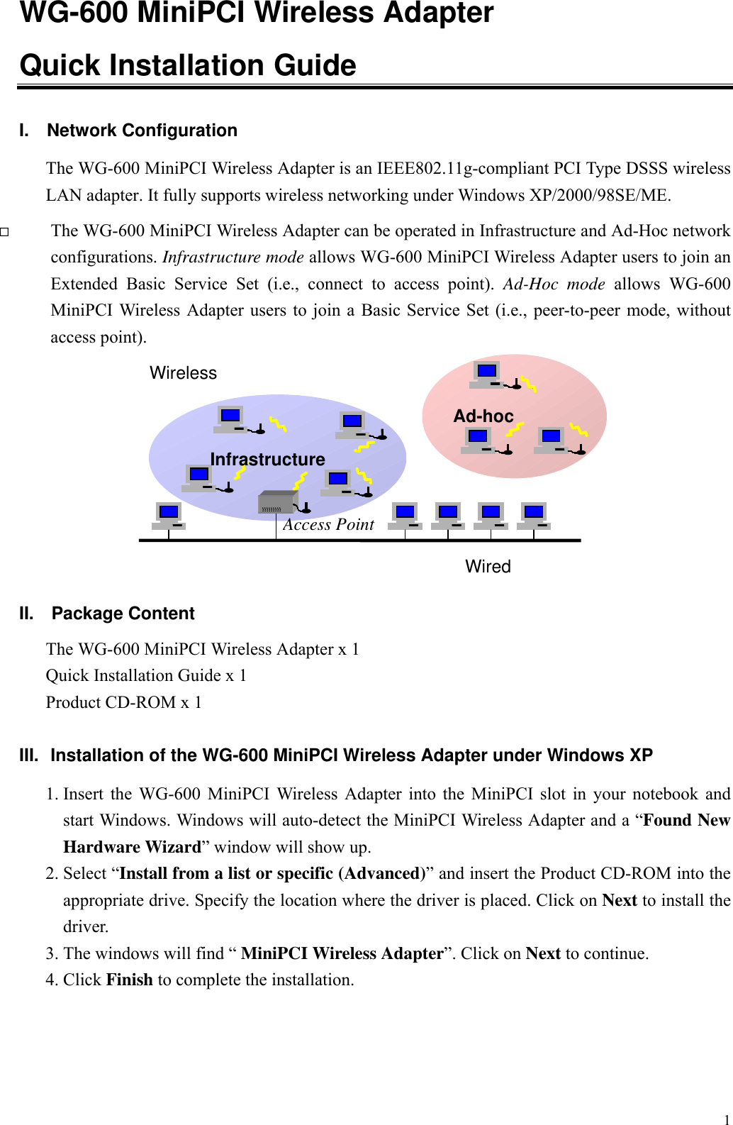
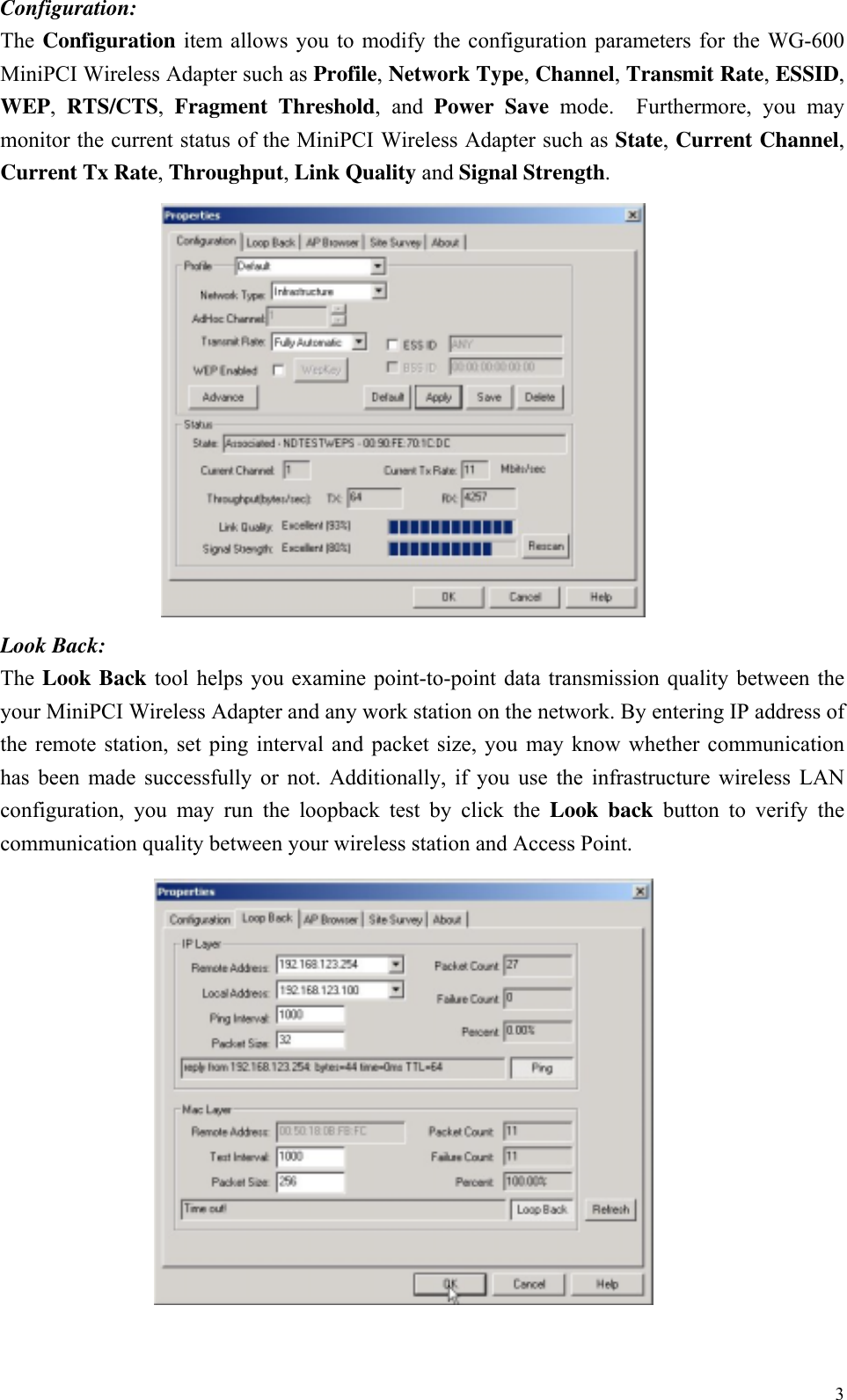
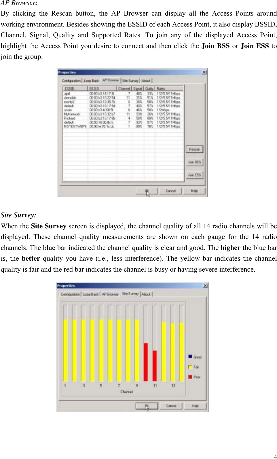
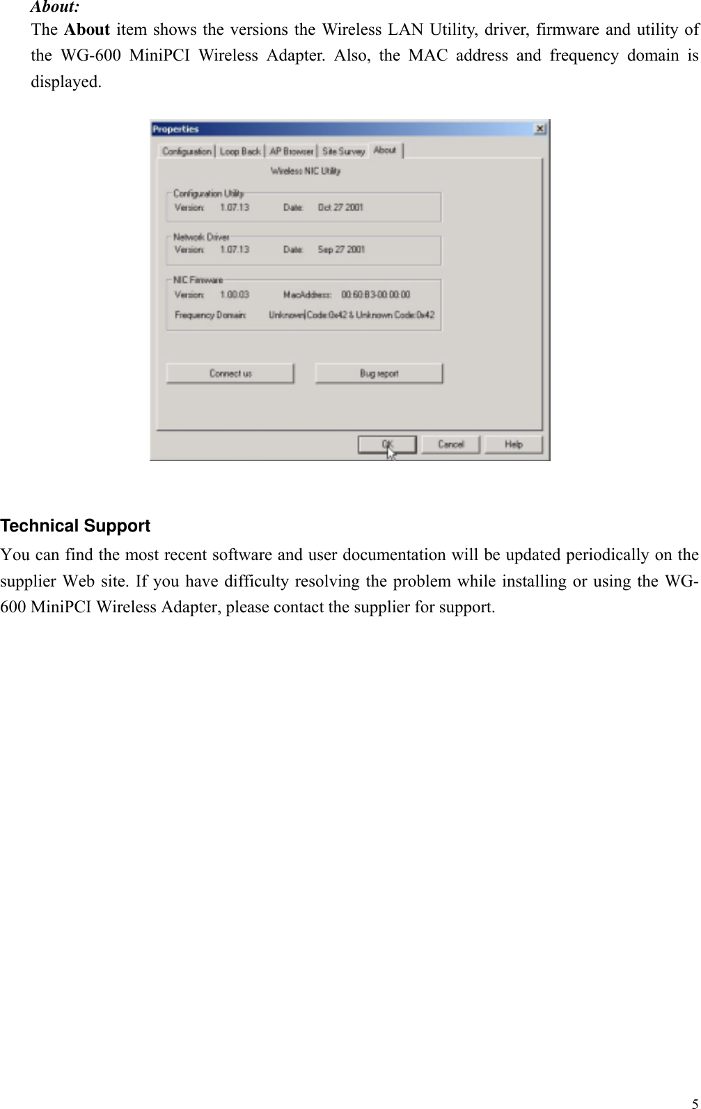
![2Installation of the WG-600 MiniPCI Wireless Adapter under Windows 20001. Insert the WG-600 MiniPCI Wireless Adapter into the MiniPCI slot in your notebook andstart Windows. Windows will auto-detect the MiniPCI Wireless Adapter and a “Found NewHardware Wizard” window will show up. Click Next to proceed.2. Select “Search for a suitable driver for my device (recommended)”. Insert the ProductCD-ROM into the appropriate drive. Specify the location where the driver is placed. Clickon Next to install the driver.3. The windows will find “ MiniPCI Wireless Adapter”. Click on Next to continue.4. Click Finish to complete the installation.Installaton of the WG-600 MiniPCI Wireless Adapter under Windows 98SE/ME1. Insert the WG-600 MiniPCI Wireless Adapter into the MiniPCI slot in your notebook andstart Windows. Windows will auto-detect new hardware and will display a “Add NewHardware Wizard” window.2. Select “Search for a best driver for your device (recommended)”. Insert the Product CD-ROM into the appropriate drive. Specify the location where the driver is placed. Click onNext to install the driver.3. The Windows will find “MiniPCI Wireless Adapter”. Click on Next to continue.4. Once the [Please insert the disk labeled “Windows 98SE/ME CD-ROM”, and thenclick OK] window appears, enter the path corresponding to the appropriate drives and clickOK.5. Click Finish to complete the installation. Restart Windows.IV. Installation of the Wireless LAN Utility1. Insert the Product CD-ROM again.2. Go the utility folder and run setup.exe.3. Follow the on-screen instructions to install the Wireless LAN Utility.4. Upon completion, go to Program Files and run the Wireless LAN Utility. The utilityinterface will then appear and at the same time its icon appears in the System Tray in thebottom right corner of your task bar.V. Usage of the Wireless LAN UtilityThe Wireless LAN Utility consists of window with 5 items for you to monitor and configurethe WG-600 MiniPCI Wireless Adapter: Configuration, Loop Back, AP Browser, SiteSurvey and About.](https://usermanual.wiki/Netgear-orporated/WG600/User-Guide-302878-Page-2.png)