Netgear orporated WGR101 Wireless Router User Manual FullManual
Netgear Incorporated Wireless Router FullManual
Users Manual Revised
May 2004 (202-10034-01)
202-10034-01
Version 1.4
May 2004
NETGEAR, Inc.
4500 Great America Parkway
Santa Clara, CA 95054 USA
Reference Manual for the
54 Mbps Wireless Travel
Router WGR101

ii
May 2004 (202-10034-01)
© 2004 by NETGEAR, Inc. All rights reserved.
Trademarks
NETGEAR is a trademark of Netgear, Inc.
Microsoft, Windows, and Windows NT are registered trademarks of Microsoft Corporation.
Other brand and product names are registered trademarks or trademarks of their respective holders.
Statement of Conditions
In the interest of improving internal design, operational function, and/or reliability, NETGEAR reserves the right to
make changes to the products described in this document without notice.
NETGEAR does not assume any liability that may occur due to the use or application of the product(s) or circuit
layout(s) described herein.
Certificate of the Manufacturer/Importer
It is hereby certified that the 54 Mbps Wireless Travel Router WGR101 has been suppressed in accordance with the
conditions set out in the BMPT-AmtsblVfg 243/1991 and Vfg 46/1992. The operation of some equipment (for example,
test transmitters) in accordance with the regulations may, however, be subject to certain restrictions. Please refer to the
notes in the operating instructions.
Federal Office for Telecommunications Approvals has been notified of the placing of this equipment on the market
and has been granted the right to test the series for compliance with the regulations.
Voluntary Control Council for Interference (VCCI) Statement
This equipment is in the second category (information equipment to be used in a residential area or an adjacent area
thereto) and conforms to the standards set by the Voluntary Control Council for Interference by Data Processing
Equipment and Electronic Office Machines aimed at preventing radio interference in such residential areas.
When used near a radio or TV receiver, it may become the cause of radio interference.
Read instructions for correct handling.
Customer Support
Refer to the Support Information Card that shipped with your 54 Mbps Wireless Travel Router WGR101 .
World Wide Web
NETGEAR maintains a World Wide Web home page that you can access at the universal resource locator (URL)
http://www.netgear.com. A direct connection to the Internet and a web browser such as Internet Explorer or Netscape are
required.

May 2004 (202-10034-01)
EN 55 022 Declaration of Conformance
This is to certify that the 54 Mbps Wireless Travel Router WGR101 is shielded against the generation of radio
interference in accordance with the application of Council Directive 89/336/EEC, Article 4a. Conformity is declared by
the application of EN 55 022 Class B (CISPR 22).
Compliance with the applicable regulations is dependent upon the use of shielded cables. It is the responsibility of the
user to procure the appropriate cables.
Countries of Operation and Conditions of Use in the European Community
This device is intended to be operated in all countries of the European Community. Requirements for indoor vs. outdoor
operation, license requirements and allowed channels of operation apply in some countries as described below.
NOTE: The user must use the configuration utility provided with this product to ensure the channels of operation are in
conformance with the spectrum usage rules for European Community countries as described below.
• This device requires that the user or installer properly enter the current country of operation in the Radio
Configuration Window as described in the user guide, before operating this device.
• This device will automatically limit the allowable channels of operation applicable to each country. Incorrectly
entering the country of operation may result in illegal operation and may cause harmful interference to other
system. The user is obligated to ensure the device is operating according to the channel limitations, indoor/outdoor
restrictions and license requirements for each European Community country as described in this document.
• This device may be operated indoors or outdoors in all countries of the European Community using the 2.4GHz
band except where noted below.
• In Italy the end-user must apply for a license from the national spectrum authority to operate this device outdoors.
• In France outdoor operation is only permitted using the 2.4 – 2.454 GHz band: Channels 1 – 7.
Federal Communications Commission (FCC) Compliance Notice: Radio
Frequency Notice
This equipment has been tested and found to comply with the limits for a Class B digital device, pursuant to
part 15 of the FCC Rules. These limits are designed to provide reasonable protection against harmful interference in a
residential installation. This equipment generates, uses, and can radiate radio frequency energy and, if not installed and
used in accordance with the instructions, may cause harmful interference to radio communications. However, there is no
guarantee that interference will not occur in a particular installation. If this equipment does cause harmful interference to
radio or television reception, which can be determined by turning the equipment off and on, the user is encouraged to try
to correct the interference by one or more of the following measures:
• Reorient or relocate the receiving antenna.
• Increase the separation between the equipment and receiver.
• Connect the equipment into an outlet on a circuit different from that to which the receiver is connected.
• Consult the dealer or an experienced radio/TV technician for help.
FCC Caution
1. FCC RF Radiation Exposure Statement: The equipment complies with FCC RF radiation exposure limits set forth
for an uncontrolled environment. This equipment should be installed and operated with a minimum distance of 20
centimeters between the radiator and your body.
2. This Transmitter must not be co-located or operating in conjunction with any other antenna or transmitter. 3.
Changes or modifications to this unit not expressly approved by the party responsible for compliance could void the
user authority to operate the equipment.
To assure continued compliance, any changes or modifications not expressly approved by the
party responsible for compliance could void the user's authority to operate this equipment.
(Example - use only shielded interface cables when connecting to computer or peripheral
devices).

May 2004 (202-10034-01)
EN 55 022 Declaration of Conformance
This is to certify that the 54 Mbps Wireless Travel Router WGR101 is shielded against the generation of radio
interference in accordance with the application of Council Directive 89/336/EEC, Article 4a. Conformity is declared by
the application of EN 55 022 Class B (CISPR 22).
Compliance with the applicable regulations is dependent upon the use of shielded cables. It is the responsibility of the
user to procure the appropriate cables.
Countries of Operation and Conditions of Use in the European Community
This device is intended to be operated in all countries of the European Community. Requirements for indoor vs. outdoor
operation, license requirements and allowed channels of operation apply in some countries as described below.
NOTE: The user must use the configuration utility provided with this product to ensure the channels of operation are in
conformance with the spectrum usage rules for European Community countries as described below.
• This device requires that the user or installer properly enter the current country of operation in the Radio
Configuration Window as described in the user guide, before operating this device.
• This device will automatically limit the allowable channels of operation applicable to each country. Incorrectly
entering the country of operation may result in illegal operation and may cause harmful interference to other
system. The user is obligated to ensure the device is operating according to the channel limitations, indoor/outdoor
restrictions and license requirements for each European Community country as described in this document.
• This device may be operated indoors or outdoors in all countries of the European Community using the 2.4GHz
band except where noted below.
• In Italy the end-user must apply for a license from the national spectrum authority to operate this device outdoors.
• In France outdoor operation is only permitted using the 2.4 – 2.454 GHz band: Channels 1 – 7.
Europe - EU Declaration of Conformity
This device is a 2.4 GHz low power RF device intended for home and office use in EU and EFTA member states. In
some EU / EFTA member states some restrictions may apply. Please contact local spectrum management authorities for
further details before putting this device into operation.
Marking by the above symbol indicates compliance with the Essential Requirements of the R&TTE Directive of the
European Union (1999/5/EC). This equipment meets the following conformance standards:
EN300 328, EN301 489-17, EN60950
May 2004 (202-10034-01)
v
Hiermit erklärt NETGEAR, Inc.die Übereinstimmung des Gerätes Radio LAN device mit den
grundlegenden Anforderungen und den anderen relevanten Festlegungen der Richtlinie 1999/5/EG.
(Wien).
Italian Con la presente NETGEAR, Inc.dichiara che questo Radio LAN device è conforme ai requisiti
essenziali ed alle altre disposizioni pertinenti stabilite dalla direttiva 1999/5/CE.
Spanish Por medio de la presente NETGEAR, Inc.declara que el Radio LAN device cumple con los
requisitos esenciales y cualesquiera otras disposiciones aplicables o exigibles de la Directiva 1999/5/
CE.
Portuguese NETGEAR, Inc.declara que este Radio LAN device está conforme com os requisitos essenciais e
outras disposições da Directiva 1999/5/CE.
Declaration of Conformity in Languages of the European Community
English Hereby, NETGEAR, Inc. declares that this Radio LAN device is in compliance with the essential
requirements and other relevant provisions of Directive 1999/5/EC.
Finnish Valmistaja NETGEAR, Inc.vakuuttaa täten että Radio LAN device tyyppinen laite on direktiivin
1999/5/EY oleellisten vaatimusten ja sitä koskevien direktiivin muiden ehtojen mukainen.
Dutch Hierbij verklaart NETGEAR, Inc.dat het toestel Radio LAN device in overeenstemming is met de
essentiële eisen en de andere relevante bepalingen van richtlijn 1999/5/EG
Bij deze NETGEAR, Inc.dat deze Radio LAN device voldoet aan de essentiële eisen en aan de
overige relevante bepalingen van Richtlijn 1999/5/EC.
French Par la présente NETGEAR, Inc.déclare que l'appareil Radio LAN device est conforme aux
exigences essentielles et aux autres dispositions pertinentes de la directive 1999/5/CE.
Par la présente, NETGEAR, Inc.déclare que ce Radio LAN device est conforme aux exigences
essentielles et aux autres dispositions de la directive 1999/5/CE qui lui sont applicables.
Swedish Härmed intygar NETGEAR, Inc.att denna Radio LAN device står I överensstämmelse med de
väsentliga egenskapskrav och övriga relevanta bestämmelser som framgår av direktiv 1999/5/EG.
Danish Undertegnede NETGEAR, Inc.erklærer herved, at følgende udstyr Radio LAN device overholder de
væsentlige krav og øvrige relevante krav i direktiv 1999/5/EF.
German Hiermit erklärt [INSERT COMPANY NAME HERE], dass sich dieser/diese/dieses Radio LAN
device in Übereinstimmung mit den grundlegenden Anforderungen und den anderen relevanten
Vorschriften der Richtlinie 1999/5/EG befindet". (BMWi)
Channel
The Wireless Channel sets the radio frequency used for communication.
•Access Points use a fixed Channel. You can select the Channel used. This allows you to choose a Channel which
provides the least interference and best performance. In the USA and Canada, 11 channel are available. If using
multiple Access Points, it is better if adjacent Access Points use different Channels to reduce interference.
• In "Infrastructure" mode, Wireless Stations normally scan all Channels, looking for a Access Point. If more than
one Access Point can be used, the one with the strongest signal is used. (This can only happen within an ESS.)
• If using "Ad-hoc" mode (no Access Point), all Wireless stations should be set to use the same Channel. However,
most Wireless stations will still scan all Channels to see if there is an existing "Ad-hoc" group they can join.

May 2004 (202-10034-01)
vi
Model Name: 54 Mbps Wireless Travel Router
Model No.: WGR101
This device complies with part 15 of the FCC rule. Operation is subject to the
following two conditions: (1) This device may not cause harmful interference, and
(2) this device must accept any interference received, including interference that
may cause undesired operation.
Contact Person: Jimmy Su
Contact Address: 4500 Great America Parkway, Santa Clara, California 95054, USA
TEL: +1-408-907-8000
FAX: +1-408-907-8097
E-MAIL: jimmy.su@netgear.com
Contents vii
May 2004 (202-10034-01)
Contents
Chapter 1
About This Manual
Audience, Scope, Conventions, and Formats ................................................................1-1
How to Use This Manual ................................................................................................1-2
How to Print this Manual .................................................................................................1-3
Chapter 2
Introduction
Key Features ..................................................................................................................2-1
802.11g Wireless Networking ...................................................................................2-2
Security ....................................................................................................................2-2
Autosensing Ethernet Connections with Auto Uplink ...............................................2-2
Extensive Protocol Support ......................................................................................2-3
Easy Installation and Management ..........................................................................2-3
Maintenance and Support ........................................................................................2-4
Package Contents ..........................................................................................................2-4
The Router’s Switch .................................................................................................2-5
The Router’s Front Panel .........................................................................................2-6
The Router’s Rear Panel .........................................................................................2-7
Chapter 3
Connecting the Router to the Internet
Prepare to Install Your Wireless Travel Router ...............................................................3-1
Setup Options Overview .................................................................................................3-2
Quick Installation: No Router Configuration or WEP Security ........................................3-4
How to Log in to the Wireless Travel Router ..................................................................3-5
Basic Wireless Security WEP Configuration ..................................................................3-8
Basic Setup Troubleshooting Tips ..................................................................................3-9
Chapter 4
Wireless Configuration
Observe Performance, Placement, and Range Guidelines ............................................4-1
May 2004 (202-10034-01)
viii Contents
Implement Appropriate Wireless Security ......................................................................4-2
Understanding Wireless Settings ...................................................................................4-3
Information to Gather Before Changing Basic Wireless Settings .............................4-6
Default Factory Settings ...........................................................................................4-7
How to Set Up and Test Basic Wireless Connectivity ..............................................4-7
How to Configure WEP ............................................................................................4-8
How to Restrict Wireless Access by MAC Address ...............................................4-10
Chapter 5
Management
Viewing Wireless Travel Router Status Information ........................................................5-1
Viewing a List of Attached Devices .................................................................................5-5
Upgrading the Router Software ......................................................................................5-6
Configuration File Management .....................................................................................5-6
Restoring and Backing Up the Configuration ...........................................................5-7
Erasing the Configuration .........................................................................................5-8
Changing the Administrator Password ...........................................................................5-8
Chapter 6
Network Configuration
Wireless Login to the Wireless Travel Router .................................................................6-1
Configuring Basic Settings Options ................................................................................6-3
Configuring WAN Setup Options ....................................................................................6-4
Setting Up a Default DMZ Server .............................................................................6-4
Respond to Ping on Internet WAN Port ...................................................................6-5
Using WAN IP Setup Options .........................................................................................6-6
Using the Router as a DHCP server ........................................................................6-7
Chapter 7
Troubleshooting
Basic Functioning ...........................................................................................................7-1
Power Light Not On ..................................................................................................7-1
Lights Never Turn Off ...............................................................................................7-2
LAN/ WAN Port Light Not On ...................................................................................7-2
Troubleshooting the Web Configuration Interface ..........................................................7-3
Troubleshooting a TCP/IP Network Using a Ping Utility .................................................7-4
Testing the LAN Path to Your Router .......................................................................7-4
Testing the Path from Your Computer to a Remote Device .....................................7-5
Contents ix
May 2004 (202-10034-01)
Restoring the Default Configuration and Password ........................................................7-5
Appendix A
Technical Specifications
Appendix B
Network, Routing, Firewall, and Basics
Related Publications ...................................................................................................... B-1
Basic Router Concepts .................................................................................................. B-1
What is a Router? ................................................................................................... B-1
Routing Information Protocol ................................................................................... B-2
IP Addresses and the Internet ....................................................................................... B-2
Netmask .................................................................................................................. B-4
Subnet Addressing .................................................................................................. B-4
Private IP Addresses ............................................................................................... B-7
Single IP Address Operation Using NAT ....................................................................... B-7
MAC Addresses and Address Resolution Protocol ................................................. B-8
Related Documents ................................................................................................. B-9
Domain Name Server .............................................................................................. B-9
IP Configuration by DHCP ........................................................................................... B-10
Internet Security and Firewalls .................................................................................... B-10
What is a Firewall? ................................................................................................ B-10
Stateful Packet Inspection ...............................................................................B-11
Denial of Service Attack ..................................................................................B-11
Ethernet Cabling ...........................................................................................................B-11
Category 5 Cable Quality ...................................................................................... B-12
Inside Twisted Pair Cables .................................................................................... B-13
Uplink Switches, Crossover Cables, and MDI/MDIX Switching ............................ B-14
Appendix C
Preparing Your Network
Preparing Your Computers for TCP/IP Networking ....................................................... C-1
Configuring Windows 95, 98, and Me for TCP/IP Networking ....................................... C-2
Install or Verify Windows Networking Components ................................................. C-2
Enabling DHCP to Automatically Configure TCP/IP Settings ................................. C-4
Selecting Windows’ Internet Access Method .......................................................... C-6
Verifying TCP/IP Properties .................................................................................... C-6
Configuring Windows NT4, 2000 or XP for IP Networking ............................................ C-7
May 2004 (202-10034-01)
xContents
Install or Verify Windows Networking Components ................................................. C-7
DHCP Configuration of TCP/IP in Windows XP, 2000, or NT4 ............................... C-8
DHCP Configuration of TCP/IP in Windows XP ..................................................... C-8
DHCP Configuration of TCP/IP in Windows 2000 ................................................ C-10
DHCP Configuration of TCP/IP in Windows NT4 .................................................. C-13
Verifying TCP/IP Properties for Windows XP, 2000, and NT4 .............................. C-15
Configuring the Macintosh for TCP/IP Networking ...................................................... C-16
MacOS 8.6 or 9.x .................................................................................................. C-16
MacOS X ............................................................................................................... C-16
Verifying TCP/IP Properties for Macintosh Computers ......................................... C-17
Verifying the Readiness of Your Internet Account ....................................................... C-18
Are Login Protocols Used? ................................................................................... C-18
What Is Your Configuration Information? .............................................................. C-18
Obtaining ISP Configuration Information for Windows Computers ....................... C-19
Obtaining ISP Configuration Information for Macintosh Computers ..................... C-20
Restarting the Network ................................................................................................ C-21
Appendix D
Wireless Networking Basics
Wireless Networking Overview ...................................................................................... D-1
Infrastructure Mode ................................................................................................. D-1
Ad Hoc Mode (Peer-to-Peer Workgroup) ................................................................ D-2
Network Name: Extended Service Set Identification (ESSID) ................................ D-2
Wireless Channels .................................................................................................. D-2
WEP Wireless Security .................................................................................................. D-4
WEP Authentication ................................................................................................ D-4
WEP Open System Authentication ......................................................................... D-5
WEP Shared Key Authentication ............................................................................ D-6
Key Size and Configuration .............................................................................. D-7
How to Use WEP Parameters ................................................................................. D-8
Glossary
List of Glossary Terms ...................................................................................................G-1
Index
About This Manual 1
May 2004 (202-10034-01)
Chapter 1
About This Manual
This chapter describes the intended audience, scope, conventions, and formats of this manual.
Audience, Scope, Conventions, and Formats
This reference manual assumes that the reader has basic to intermediate computer and Internet
skills. However, basic computer network, Internet, firewall, and VPN technologies tutorial
information is provided in the Appendices and on the Netgear website.
This guide uses the following typographical conventions:
This guide uses the following formats to highlight special messages:
This manual is written for the WGR101 wireless travel router according to these specifications.:
Table 1-1. Typographical Conventions
italics Emphasis, books, CDs, URL names
bold times roman User input
courier font Screen text, file and server names, extensions, commands, IP addresses
Note: This format is used to highlight information of importance or special interest.
Table 1-2. Manual Scope
Product Version 54 Mbps Wireless Travel Router WGR101
Manual Publication Date May 2004
Note: Product updates are available on the NETGEAR Web site at
www.netgear.com/support/main.asp.
Reference Manual for the 54 Mbps Wireless Travel Router WGR101
2About This Manual
May 2004 (202-10034-01)
How to Use This Manual
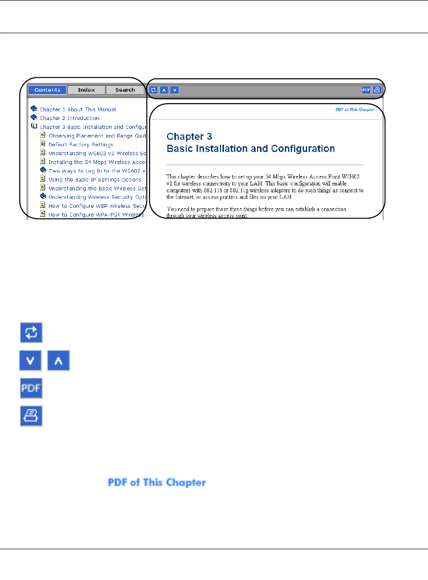
The HTML version of this manual includes a variety of navigation features as well as links to PDF
versions of the full manual and individual chapters.
Figure 1 -1: HTML version of this manual
1. Left pane. Use the left pane to view the Contents, Index, Search, and Favorites tabs.
To view the HTML version of the manual, you must have a version 4 or later browser with
JavaScript enabled.
2. Toolbar buttons. Use the toolbar buttons across the top to navigate, print pages, and more.
The Show in Contents button locates the current topic in the Contents tab.
Previous/Next buttons display the previous or next topic.
The PDF button links to a PDF version of the full manual.
The Print button prints the current topic. Click this button when a step-by-step
procedure is displayed to send the entire procedure to your printer. You do not
have to worry about specifying the correct range of pages.
3. Right pane. Use the right pane to view the contents of the manual. Also, each page of the
manual includes a link at the top right which links to a PDF file
containing just the currently selected chapter of the manual.
12
3
Reference Manual for the 54 Mbps Wireless Travel Router WGR101
About This Manual 3
May 2004 (202-10034-01)
How to Print this Manual
To print this manual you can choose one of the following several options, according to your needs.
•Printing a “How To” Sequence of Steps in the HTML View.
Use the Print button on the upper right of the toolbar to print the currently displayed
topic. Use this button when a step-by-step procedure is displayed to send the entire procedure
to your printer. You do not have to worry about specifying the correct range of pages.
•Printing a Chapter.
Use the link at the top right of any page.
– Click “PDF of This Chapter” link at the top right of any page in the chapter you want to
print. The PDF version of the chapter you were viewing opens in a browser window.
Note: Your computer must have the free Adobe Acrobat reader installed in order to view
and print PDF files. The Acrobat reader is available on the Adobe web site at
http://www.adobe.com.
– Click the print icon in the upper left of the window.
Tip: If your printer supports printing two pages on a single sheet of paper, you can save
paper and printer ink by selecting this feature.
•Printing the Full Manual.
Use the PDF button in the toolbar at the top right of the browser window.
– Click the PDF button on the upper right of the toolbar. The PDF version of the
chapter you were viewing opens in a browser window.
– Click the print icon in the upper left of the window.
Tip: If your printer supports printing two pages on a single sheet of paper, you can save
paper and printer ink by selecting this feature.

Reference Manual for the 54 Mbps Wireless Travel Router WGR101
4About This Manual
May 2004 (202-10034-01)
Introduction 2-1
May 2004 (202-10034-01)
Chapter 2
Introduction
Congratulations on your purchase of the NETGEAR® 54 Mbps Wireless Travel Router WGR101 .
The WGR101 wireless travel router provides connection for multiple computers to the Internet
through an RJ45 wall slot or an external broadband access device (such as a cable modem) that is
normally intended for use by a single computer. This chapter describes the features of the
NETGEAR 54 Mbps Wireless Travel Router WGR101 .
Key Features
The 54 Mbps Wireless Travel Router WGR101 with 4-port switch connects one or more wireless
computers to the Internet through an RJ45 slot, router, or cable modem.
With minimum setup, you can install and use the router within minutes.
The WGR101 wireless travel router provides the following features:
• 802.11g wireless networking, with the ability to operate in 802.11g-only, or 802.11b+g modes.
• Easy, web-based setup for installation and management.
• Ethernet connection to an RJ45 wall slot, router, or cable modem.
• Extensive Protocol Support.
• Login capability.
• Front panel LEDs for easy monitoring of status and activity.
• Flash memory for firmware upgrade.
Note: This manual provides information on the complete features as of the date of
publication. Earlier versions of this product may not have all the features presented in
this manual. Check the NETGEAR Web site at www.netgear.com/support/main.asp
where you will find product firmware updates for your WGR101.

Reference Manual for the 54 Mbps Wireless Travel Router WGR101
2-2 Introduction
May 2004 (202-10034-01)
802.11g Wireless Networking
The WGR101 wireless travel router includes an 802.11g wireless access point, providing
continuous, high-speed 54 Mbps access between your wireless and Ethernet devices. The access
point provides:
• 802.11g wireless networking at up to 54 Mbps.
• 802.11g wireless networking, with the ability to operate in 802.11g-only, 802.11b-only, or
802.11g and b modes, providing backwards compatibility with 802.11b devices or dedicating
the wireless network to the higher bandwidth 802.11g devices.
• 64-bit and 128-bit WEP encryption security.
• WEP keys can be generated manually or by passphrase.
• WPA-PSK support. Support for Wi-Fi Protected Access (WPA) data encryption which
provides strong data encryption and authentication based on a pre-shared key.
• Wireless access can be restricted by MAC address.
• Wireless network name broadcast can be turned off so that only devices that have the network
name (SSID) can connect.
Security
The WGR101 wireless travel router is equipped with several features designed to maintain
security, as described in this section.
• Computers Hidden by NAT
NAT opens a temporary path to the Internet for requests originating from the local network.
Requests originating from outside the LAN are discarded, preventing users outside the LAN
from finding and directly accessing the computers on the LAN.
Autosensing Ethernet Connections with Auto Uplink
With its internal 8-port 10/100 switch, the WGR101 can connect to either a 10 Mbps standard
Ethernet network or a 100 Mbps Fast Ethernet network. Both the LAN and WAN interfaces are
autosensing and capable of full-duplex or half-duplex operation.

Reference Manual for the 54 Mbps Wireless Travel Router WGR101
Introduction 2-3
May 2004 (202-10034-01)
The router incorporates Auto UplinkTM technology. Each Ethernet port will automatically sense
whether the Ethernet cable plugged into the port should have a ‘normal’ connection such as to a
computer or an ‘uplink’ connection such as to a switch or hub. That port will then configure itself
to the correct configuration. This feature also eliminates the need to worry about crossover cables,
as Auto Uplink will accommodate either type of cable to make the right connection.
Extensive Protocol Support
The WGR101 wireless travel router supports the Transmission Control Protocol/Internet Protocol
(TCP/IP) and Routing Information Protocol (RIP). For further information about TCP/IP, refer to
Appendix B, “Network, Routing, Firewall, and Basics.”
• IP Address Sharing by NAT
The WGR101 wireless travel router allows several networked computers to share an Internet
account using only a single IP address, which may be statically or dynamically assigned by
your Internet service provider (ISP). This technique, known as NAT, allows the use of an
inexpensive single-user ISP account.
• Automatic Configuration of Attached computers by DHCP
The WGR101 wireless travel router dynamically assigns network configuration information,
including IP, gateway, and domain name server (DNS) addresses, to attached computers on the
LAN using the Dynamic Host Configuration Protocol (DHCP). This feature greatly simplifies
configuration of computers on your local network.
• DNS Proxy
When DHCP is enabled and no DNS addresses are specified, the router provides its own
address as a DNS server to the attached computers. The router obtains actual DNS addresses
from the ISP during connection setup and forwards DNS requests from the LAN.
Easy Installation and Management
You can install, configure, and operate the 54 Mbps Wireless Travel Router WGR101 within
minutes after connecting it to the network. The following features simplify installation and
management tasks:
• Browser-based management
Browser-based configuration allows you to easily configure your router from almost any type
of personal computer, such as Windows, Macintosh, or Linux. Online help documentation is
built into the browser-based Web Management Interface.

Reference Manual for the 54 Mbps Wireless Travel Router WGR101
2-4 Introduction
May 2004 (202-10034-01)
• Firmware Update
The WGR101 wireless travel router can be updated if a newer version of firmware is available.
This lets you take advantage of product enhancements for your WGR101 as soon as they
become available.
• Visual monitoring
The WGR101 wireless travel router’s front panel LEDs provide an easy way to monitor its
status and activity.
Maintenance and Support
NETGEAR offers the following features to help you maximize your use of the WGR101 wireless
travel router:
• Flash memory for firmware upgrade
• Free technical support seven days a week, twenty-four hours a day
Package Contents
The product package should contain the following items:
• 54 Mbps Wireless Travel Router WGR101 .
•AC power adapter.
• Category 5 (CAT5) Ethernet cable.
•NETGEAR 54 Mbps Wireless Travel Router WGR101 Resource CD (230-10081-01),
including:
— This guide.
— Application Notes and other helpful information.
•.
• Registration, Warranty Card, and Support Information Card.
If any of the parts are incorrect, missing, or damaged, contact your NETGEAR dealer. Keep the
carton, including the original packing materials, in case you need to return the router for repair.
Reference Manual for the 54 Mbps Wireless Travel Router WGR101
Introduction 2-5
May 2004 (202-10034-01)
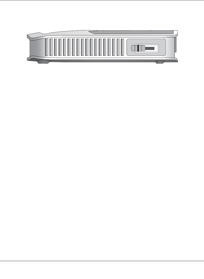
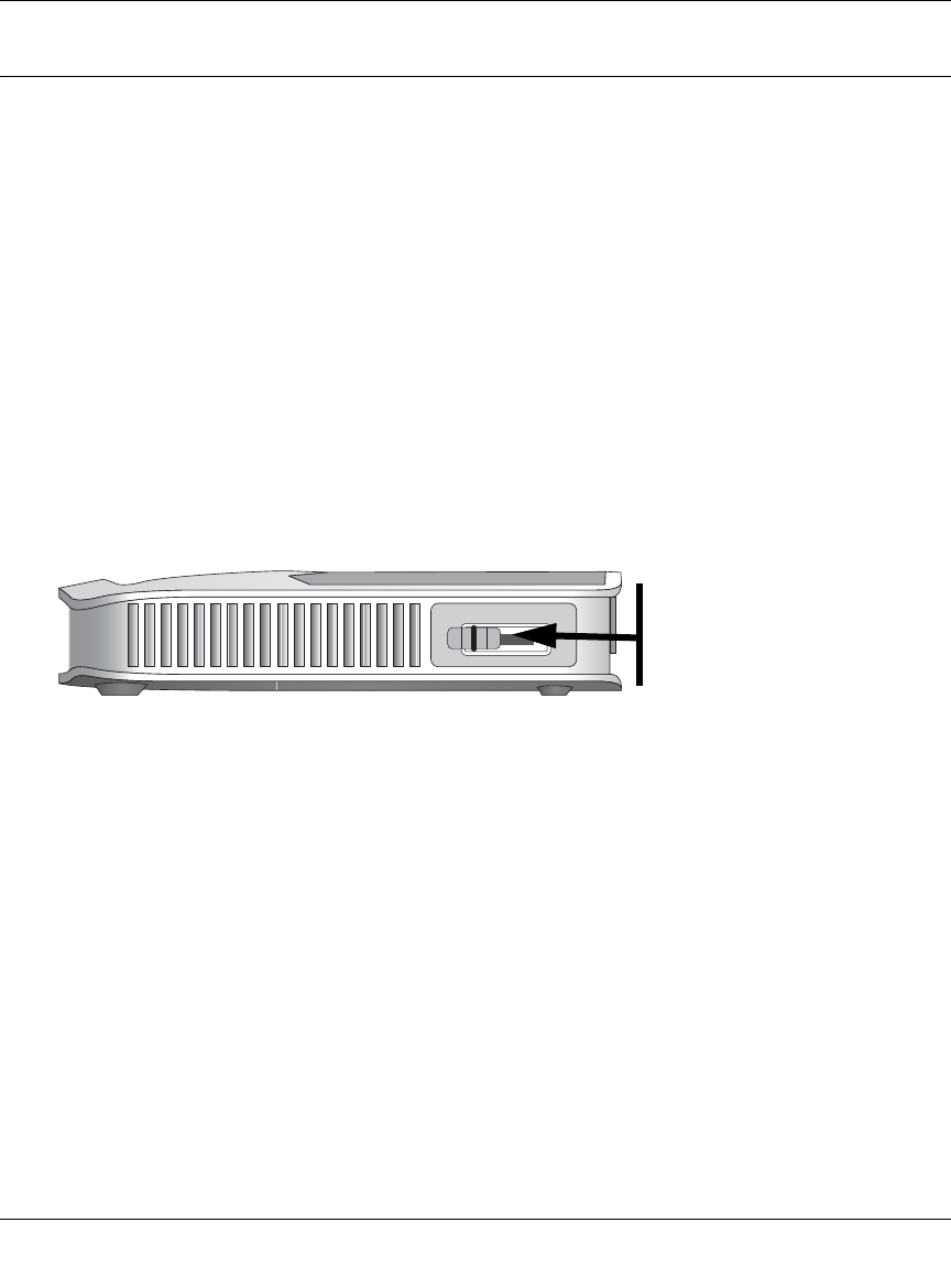
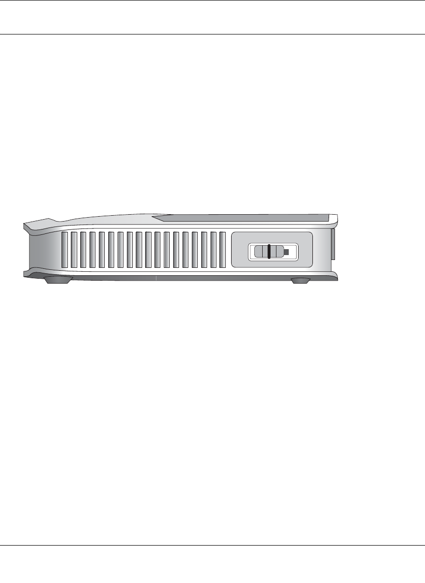
The Router’s Switch
Figure 2-1: WGR101, Side View
The side of the WGR101 Travel Router has a four-position switch. It ships in position 1, which is
used when connecting to the router as a single user. The switch position functions are as follows:
•Switch position 1: single wireless computer only access, no configuration access
•Switch position 2: configuration and multiple wireless computer access
•Switch position 3: configuration only via Ethernet or wirelessly connected computer
•Switch position 4: unused at this time
For information about changing the switch position for multiple computers to share the WGR101
Travel Router, or to configure WEP security, refer to “Setup Options Overview” in Chapter 3.
3WITCHINPOSITION
Reference Manual for the 54 Mbps Wireless Travel Router WGR101
2-6 Introduction
May 2004 (202-10034-01)
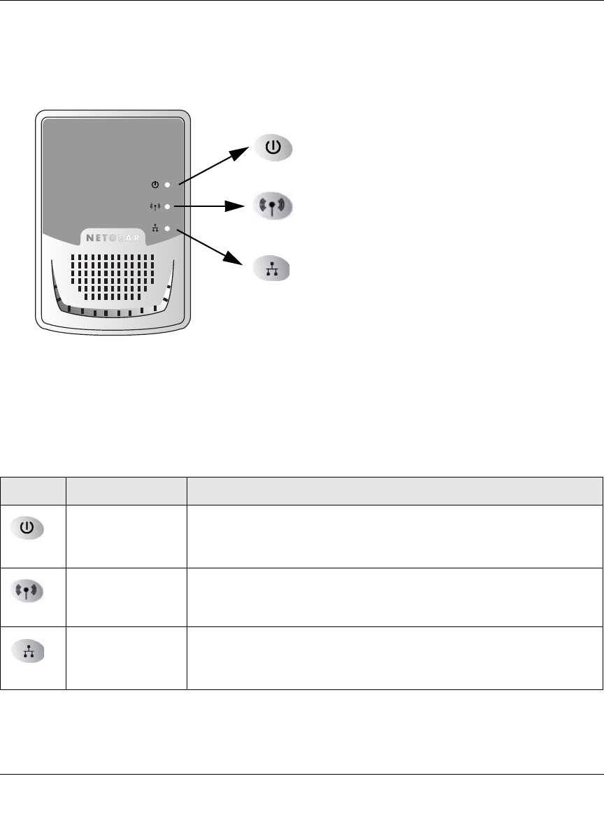
The Router’s Front Panel
The front panel of the WGR101 wireless travel router contains the status lights described below.
Figure 2-2: WGR101 Front Panel
You can use the status lights to verify connections. Viewed from left to right, the table below
describes the lights on the front panel of the router.
Table 2-1. Status Light Descriptions
Label Activity Description
Power
On Green Solid
Off Power is supplied to the router.
Power is not supplied to the router.
Wireless
On Green Solid
Blink Green
Off
The router has located a wireless connection and is ready for use.
Data is being transmitted or received.
No wireless connection is available.
Ethernet
On Green Solid
Blink Green
Off
Ethernet is connected.
Data is being transmitted or received.
No link is detected on this port.
Ethernet Port
Wireless Port
Power
Reference Manual for the 54 Mbps Wireless Travel Router WGR101
Introduction 2-7
May 2004 (202-10034-01)
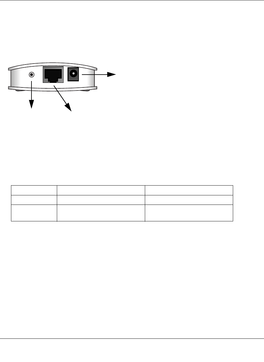
The Router’s Rear Panel
The rear panel of the router is shown below.
Viewed from left to right, the rear panel contains the following features:
Figure 2-3: WGR101 Rear Panel
• Reset: This push button can reset the router to the last settings, or reset to the factory default
settings.
• Ethernet: This port is used for Internet (WAN) connection via an RJ45 wall slot, router, or
cable modem. It is also used as a LAN port to connect the router to a local computer.
• Power: The AC power adapter outlet.
If you want to: Hold Reset button down Release Reset button
Reset After power-on When power LED is still on
Reset to factory After power-on for about five
seconds When the Power LED is flashing
Power
Ethernet
Reset
WAN/LAN Port
Button

Reference Manual for the 54 Mbps Wireless Travel Router WGR101
2-8 Introduction
May 2004 (202-10034-01)

Connecting the Router to the Internet 3-1
May 2004 (202-10034-01)
Chapter 3
Connecting the Router to the Internet
This chapter describes how to set up the router on your local area network (LAN) and connect to
the Internet. You will find out how to configure your 54 Mbps Wireless Travel Router WGR101
for Internet access.
Prepare to Install Your Wireless Travel Router
Before proceeding with the wireless travel router installation, familiarize yourself with the
contents of the NETGEAR 54 Mbps Wireless Travel Router WGR101 Resource CD
(230-10081-01), especially this manual and the animated tutorials.
For the initial setup of your router, you will need to connect a computer to the router. This
computer has to be set to automatically get its TCP/IP configuration from the router via DHCP.
Note: For help with DHCP configuration, please use the Windows TCP/IP Configuration
Tutorials on the NETGEAR 54 Mbps Wireless Travel Router WGR101 Resource CD
(230-10081-01), or refer to Appendix C, “Preparing Your Network.
Reference Manual for the 54 Mbps Wireless Travel Router WGR101
3-2 Connecting the Router to the Internet
May 2004 (202-10034-01)
Setup Options Overview
Locate the recommended setup for the WGR101 Travel Router on the chart below.
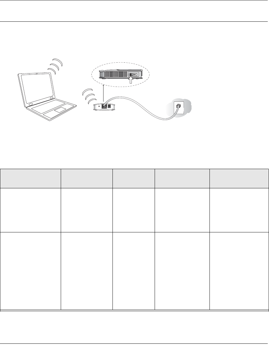
Figure 3-1: Single User Scenarios
Type of Use Recommended
Setup Application
Usage Switch Position on
the Unit Comment
One computer access,
casual use, no
sensitive data.
Quick Installation
(No WEP security) Exclusive
access for the
first computer
to select this
SSID.
1
(default setting) No configuration
required.
One computer working
in a setting such as a
hotel room where
others may abruptly
connect to this SSID.
Or, working with
sensitive data and
needing to encrypt and
use a secure wireless
connection.
Single user with
WEP security.
NETGEAR
recommends this
setup.
Exclusive
access and
reserves the
connection for
you with
matching WEP
keys.
First, change to
position 3 to
configure WEP
security, then
change to position 1
to connect as a
single user with
WEP security.
See instructions in the
User manual for
configuring WEP
security settings.
3WITCHPOSITION
,!.
Reference Manual for the 54 Mbps Wireless Travel Router WGR101
Connecting the Router to the Internet 3-3
May 2004 (202-10034-01)
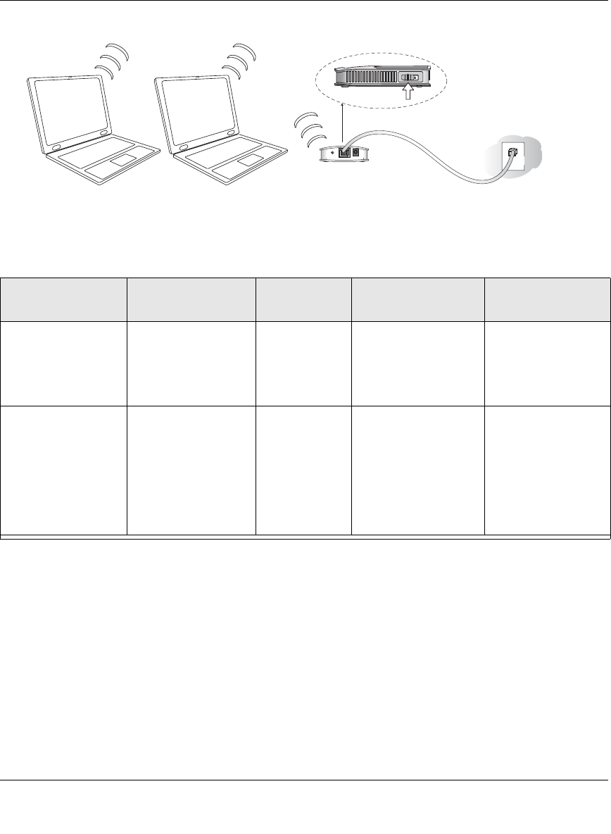
Figure 3-2: Multiple User Scenarios
Type of Use Recommended
Setup Application
Usage Switch Position on
the Unit Comment
Multiple computers,
casual use, no
sensitive data.
Quick Installation (No
WEP Security),
Multiple user switch
position
Shared among
computers that
use this SSID.
2 No configuration
required.
Multiple computers
working where
others may
accidentally connect
to this SSID.
Working with
sensitive data.
Installation with WEP
Security, multiple
user switch position.
Shared access,
and reserves
connection for
computers with
matching SSID
and WEP keys.
First, change to 3 to
configure WEP
security settings; then
change to position 2
to connect as a single
user with WEP
security
See instructions
below for configuring
WEP security
settings.
3WITCHPOSITION
,!.
Reference Manual for the 54 Mbps Wireless Travel Router WGR101
3-4 Connecting the Router to the Internet
May 2004 (202-10034-01)
Quick Installation: No Router Configuration or WEP Security
These instructions assume the following:
• You will connect the WGR101 wireless travel router to an RJ45 wall slot in the office or hotel,
or a broadband router at home
• You will not use wireless WEP security
• One or more wireless computers will connect to the WGR101 wireless travel router.
Use WEP (“Basic Wireless Security WEP Configuration” on page 3-8) to protect sensitive data.
1. First, install the Travel Router
a. Connect an Ethernet cable to the port on the WGR101 Travel Router. If you are traveling,
connect the other end of the cable to an RJ45 slot in the wall. If you are home or in an
office, connect the other end of the cable to a switch, router, or cable modem with a
broadband Internet connection.
Figure 3-3: Switch position 3
b. The WGR101 wireless travel router ships with the switch in position 1 for a single user. If
multiple computers will use the travel router, change the switch position to 2.
c. Connect the power cord to the Travel Router and plug it into an outlet. The Power LED
lights up. The Travel Router automatically broadcasts a wireless signal.
2. Now, configure your wireless computer(s)
a. On your computer, set NETGEAR-TRAVEL as the SSID for each computer that will use
the Travel Router.
Tip: If you are typing the SSID, note that it is case sensitive and must match the WGR101
Travel Router SSID exactly.
b. The Wireless LED on the Travel Router is on when a wireless connection is available.
This LED flashes during data transfer.
Position 1: Single User
Position 2: Multiple Users
Reference Manual for the 54 Mbps Wireless Travel Router WGR101
Connecting the Router to the Internet 3-5
May 2004 (202-10034-01)
How to Log in to the Wireless Travel Router
You can always connect to the router to change its settings. These two switch settings enable you
to log in:
•Switch position 1: single wireless computer only access, no configuration access
•Switch position 2: configuration and multiple wireless computer access as explained in
“Network Configuration” on page 6-1.
•Switch position 3: configuration only via Ethernet or wirelessly connected computer as
explained in “Basic Wireless Security WEP Configuration” on page 3-8 below
•Switch position 4: unused at this time
Follow these procedures to log in to the wireless travel router.
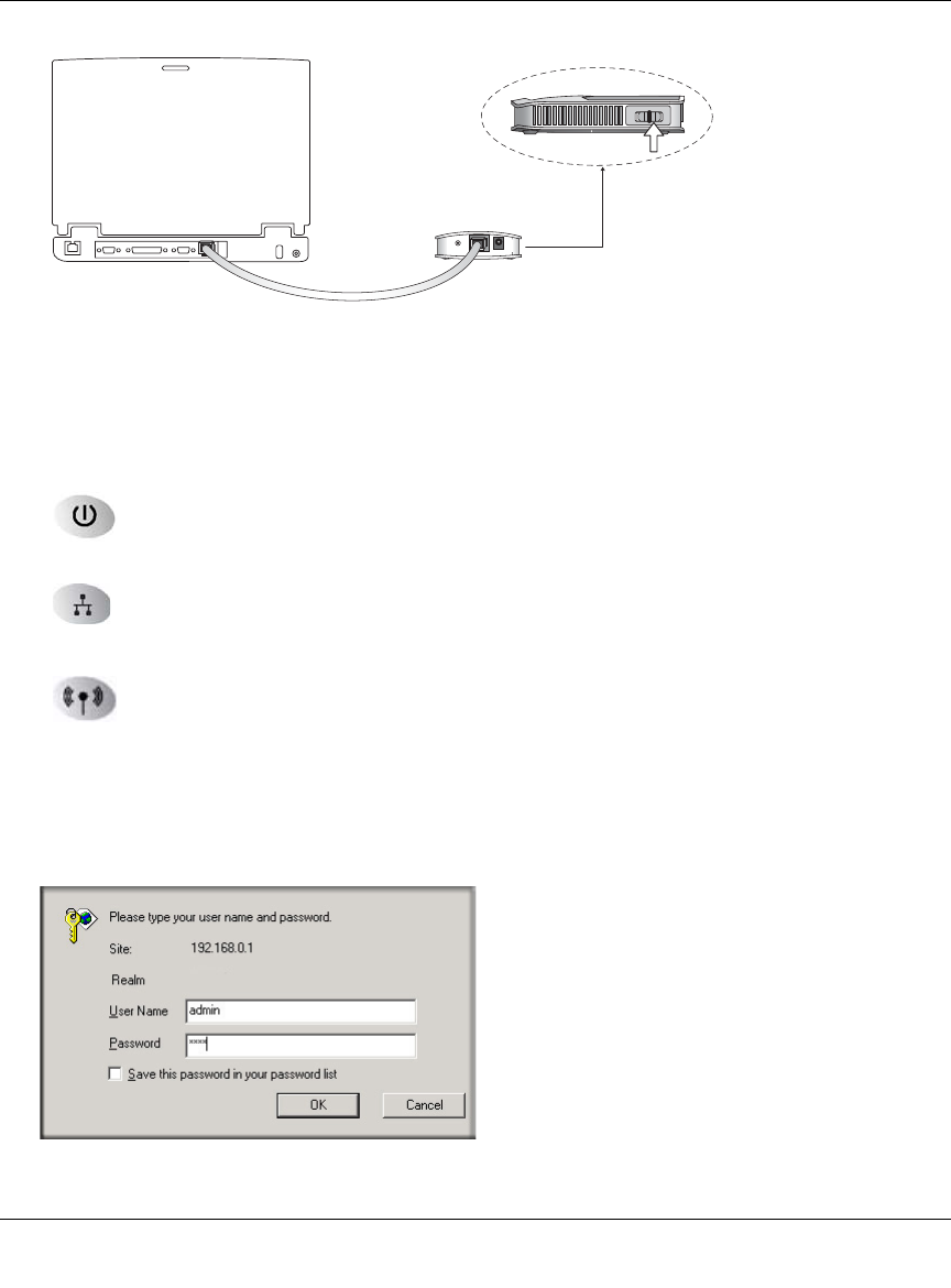
Figure 3-4: Switch position 3
1. Set the switch to position 3.
2. Connect the power cord to the wireless travel router and plug it into an outlet. The Power LED
lights up.
Warning: Be sure to power on the wireless travel router before connecting the cable from the
computer. If you do not observe this sequence, you computer may time out and fail to connect.
3WITCHINPOSITION
Reference Manual for the 54 Mbps Wireless Travel Router WGR101
3-6 Connecting the Router to the Internet
May 2004 (202-10034-01)
Figure 3-5: Computer connected via Ethernet cable to WGR101 wireless travel router
3. Connect an Ethernet cable to the wireless travel router.
Check the status lights and verify the following:
Power: When you first turn on the router, the power light blinks during the
diagnostic self test, then turns solid green.
Ethernet: The Ethernet port light on the wireless travel router should be lit. If not,
make sure the Ethernet cable is securely attached.
Wireless: The Wireless light should be lit. If the Wireless light is not lit, see the
Basic Setup Troubleshooting Tips below.
4. Open a Web browser such as Internet Explorer on the computer to connect to the wireless
travel router. The wireless travel router will automatically connecting to the browser.
A login window like the one shown below opens:
Figure 3-6: Login window
3WITCHPOSITION
Reference Manual for the 54 Mbps Wireless Travel Router WGR101
Connecting the Router to the Internet 3-7
May 2004 (202-10034-01)
When prompted, enter admin for the router user name and password for the router password,
both in lower case letters.
The WGR101 wireless travel router and display the home page as shown in below.
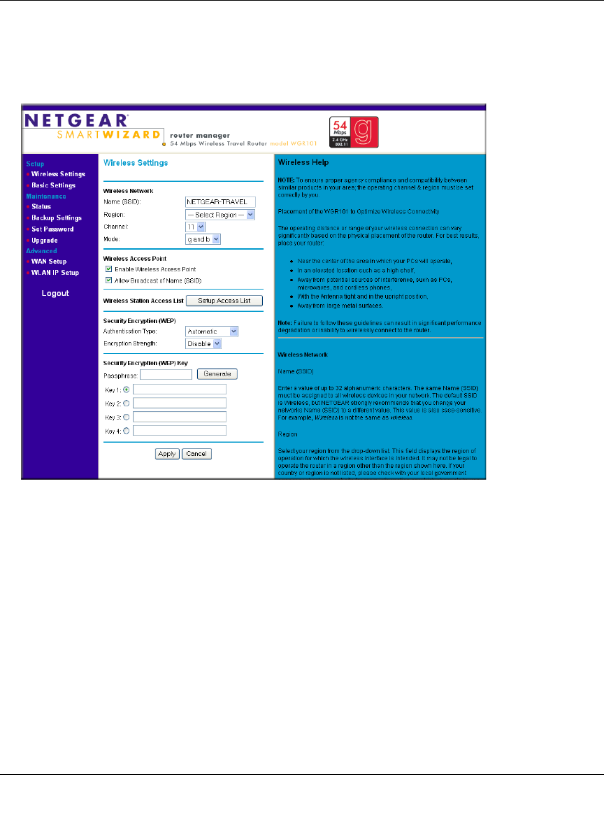
Figure 3-7: Switch position 3 login result: WGR101 wireless settings page
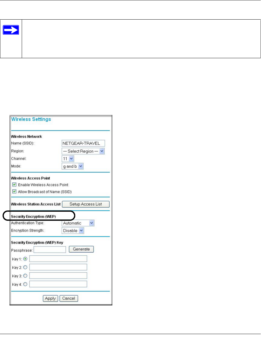
The browser will then display the WGR101 wireless settings page.
You can set the wireless security options on this page. Use the procedure below for basic
wireless WEP configuration, or see “Wireless Configuration” on page 4-1 for a full
explanation of all the wireless options.
If you do not click Logout, the wireless travel router will wait 5 minutes after there is no
activity before it automatically logs you out.
Reference Manual for the 54 Mbps Wireless Travel Router WGR101
3-8 Connecting the Router to the Internet
May 2004 (202-10034-01)
Basic Wireless Security WEP Configuration
The procedure provides instructions for basic wireless security configuration for single or multiple
users. For full instructions on setting the wireless settings, see “Wireless Configuration” on
page 4-1.
1. LOG IN TO THE WGR101 WIRELESS TRAVEL ROUTER (SEE PAGE 3-5)
The WGR101 wireless travel router and display the wireless settings page as shown in below.
Figure 3-8: Login result: WGR101 home page
Note: If you did not connect to the router, verify that your computer is set up for DHCP. For
help with this, please see the animated tutorials on the CD or Appendix C, “Preparing Your
Network.
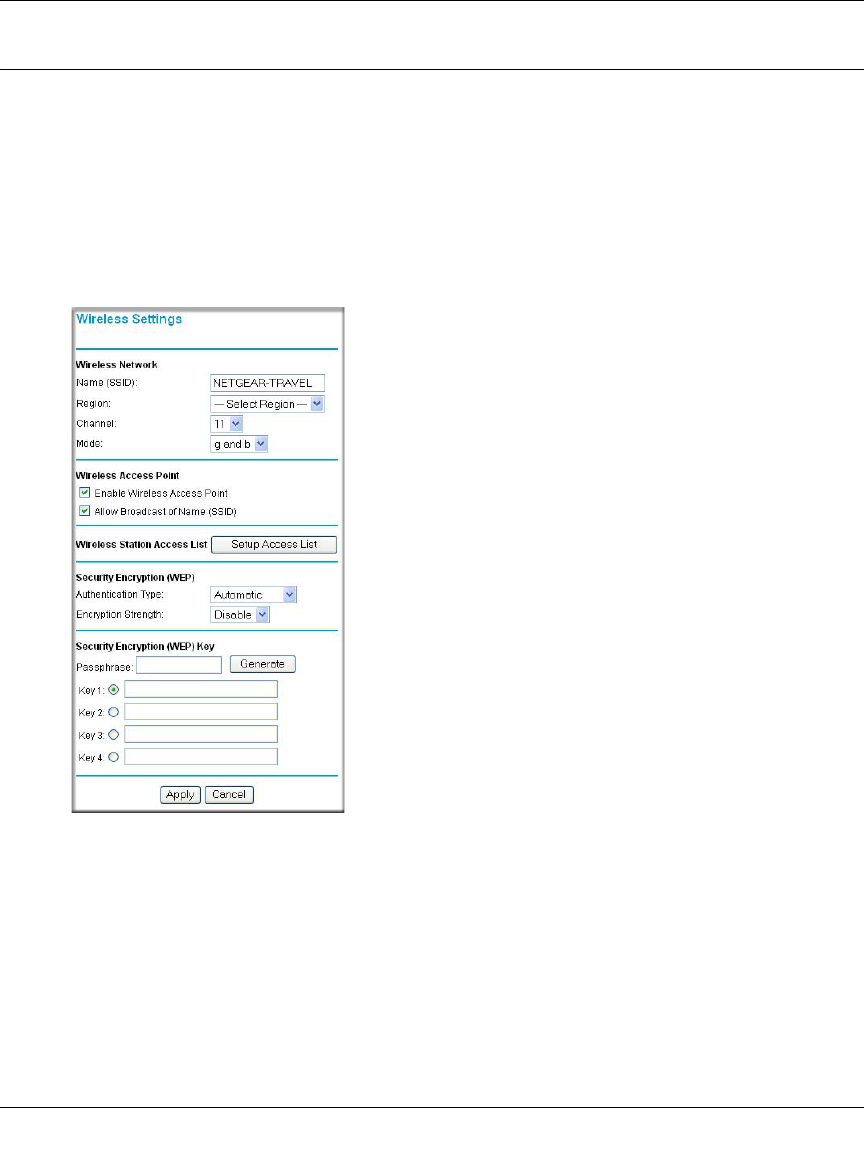
2. CUSTOMIZE THE WEP WIRELESS SECURITY SETTINGS
a. The Wireless Settings page shows NETGEAR-TRAVEL as the Name (SSID).
b. In the Region field, choose the country where you are located.

Reference Manual for the 54 Mbps Wireless Travel Router WGR101
Connecting the Router to the Internet 3-9
May 2004 (202-10034-01)
c. Select the Encryption Strength (128 bit or 64 bit) for Security Encryption (WEP).
d. Enter a Passphrase for the Security Encryption (WEP) key. After configuration the
Passphrase can be used to configure NETGEAR equipment instead of entering the WEP
number.
e. Click Generate to create the WEP key. If using a Passphrase, write it down. Otherwise,
write down the WEP number. This number is needed to configure your computer to work
with the Travel Router.
f. Click Apply to use the WEP keys.
3. CONFIGURE YOUR WIRELESS COMPUTER(S)
a. Set NETGEAR-TRAVEL as the SSID for each computer that will use the Travel Router.
Tip: If you are typing the SSID, note that it is case sensitive and must match the WGR101
Travel Router SSID exactly.
b. The Wireless LED on the Travel Router is on when a wireless connection is available.
This LED flashes during data transfer.
Basic Setup Troubleshooting Tips
Here are some tips for correcting simple problems that prevent you from connecting to the Internet
or connecting to the wireless travel router.
Make sure the network settings of the computer are correct.
• LAN and wirelessly connected computers must be configured to obtain an IP address
automatically via DHCP. For instructions on how to do this, please see the animated tutorials
on the NETGEAR 54 Mbps Wireless Travel Router WGR101 Resource CD (230-10081-01) or
Appendix C, “Preparing Your Network.”
• The switch on the Travel router must be in position 1 for a single user or in position 2 for
multiple users.
• If your hotel asks you to configure your PC with a fixed IP and you want to use the Travel
Router with multiple computers, you may need to adjust the Basic Settings. See “Network
Configuration” on page 6-1.
• Do not connect the Travel Router directly to a DSL modem. Connect the Travel Router to a
switch or another router that is connected to the DSL modem.

Reference Manual for the 54 Mbps Wireless Travel Router WGR101
3-10 Connecting the Router to the Internet
May 2004 (202-10034-01)
• If you are using the Travel Router with multiple users, it works as a secondary router. The
primary router may be set up to block parameters such as ftp or TCPIP. Check the settings on
the primary router.
• The Travel Router default IP setting is 192.168.0.1 with the user name of admin and the
password of password. If you connect the Travel Router to another router that also is set as
192.168.0.x, you must change the WGR101 wireless travel router setting so that it does not
conflict.
Check the router status lights to verify correct router operation.
• During normal operation, the Travel Router Power LED is solid green, and the Ethernet and
Wireless LEDS are solid green, or flashing during data transfer.
• If the Power light does not turn solid green within 2 minutes after turning on the router, reset
the router according to the instructions in “Restoring the Default Configuration and Password”
on page 7-5.
• If the Wireless light does not come on, verify that the wireless feature is turned on according to
the instructions in “Restoring the Default Configuration and Password” on page 7-5.
• If the status lights are normal and there is no Internet connection, use an Ethernet cable to
connect the PC directly to the RJ45 slot in the wall. If you are able to connect to the Internet,
this indicates a problem with the wireless connection or the SSID.
Make sure the wireless settings in the computer and router are set correctly.
• The Wireless Network Name (SSID) and WEP settings of the router and wireless computer
must match exactly. The SSID is case sensitive.
• If you are a single user and are not using WEP security, another user may be connected to this
SSID. Repower the Travel Router to clear the connection, and retry. If the problem persists,
configure the router to use WEP to reserve the connection for you.
• When working in the default single user configuration, only one connection to the Internet is
allowed.

Reference Manual for the 54 Mbps Wireless Travel Router WGR101
Connecting the Router to the Internet 3-11
May 2004 (202-10034-01)
Note: Product updates and support information are available on the NETGEAR Web site
at www.netgear.com/support/main.asp.

Reference Manual for the 54 Mbps Wireless Travel Router WGR101
3-12 Connecting the Router to the Internet
May 2004 (202-10034-01)
Wireless Configuration 4-1
May 2004 (202-10034-01)
Chapter 4
Wireless Configuration
This chapter describes how to configure the wireless features of your WGR101 wireless travel
router. In planning your wireless network, you should consider the level of security required. You
should also select the physical placement of your firewall in order to maximize the network speed.
For further information on wireless networking, refer to in Appendix D, “Wireless Networking
Basics.
Observe Performance, Placement, and Range Guidelines
The operating distance or range of your wireless connection can vary significantly based on the
physical placement of the wireless firewall. The latency, data throughput performance, and
notebook power consumption of wireless adapters also vary depending on your configuration
choices.
For best results, place your firewall:
• Near the center of the area in which your computers will operate.
• In an elevated location such as a high shelf where the wirelessly connected computers have
line-of-sight access (even if through walls).
• Away from sources of interference, such as computers, microwaves, and 2.4 GHz cordless
phones.
• Away from large metal surfaces.
The time it takes to establish a wireless connection can vary depending on both your security
settings and placement. WEP connections can take slightly longer to establish. Also, WEP
encryption can consume more battery power on a notebook computer.
Note: Failure to follow these guidelines can result in significant performance
degradation or inability to wirelessly connect to the router. For complete range/
performance specifications, please see Appendix A, “Technical Specifications.”
Reference Manual for the 54 Mbps Wireless Travel Router WGR101
4-2 Wireless Configuration
May 2004 (202-10034-01)
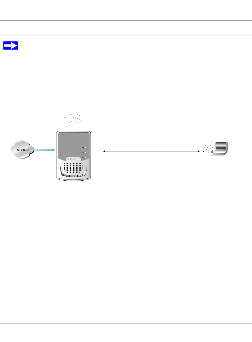
Implement Appropriate Wireless Security
Unlike wired network data, your wireless data transmissions can be received well beyond your
walls by anyone with a compatible adapter. For this reason, use the security features of your
wireless equipment. The WGR101 wireless travel router provides highly effective security
features which are covered in detail in this chapter. Deploy the security features appropriate to
your needs.
Figure 4-1: Wireless data security options
There are several ways you can enhance the security of you wireless network.
•Restrict Access Based on MAC Address. You can restrict access to only trusted computers o
that unknown computers cannot wirelessly connect to the WGR101. MAC address filtering
adds an obstacle against unwanted access to your network, but the data broadcast over the
wireless link is fully exposed.
•Turn Off the Broadcast of the Wireless Network Name SSID. If you disable broadcast of
the SSID, only devices that have the correct SSID can connect. This nullifies the wireless
network ‘discovery’ feature of some products such as Windows XP, but the data is still fully
exposed to a determined snoop using specialized test equipment like wireless sniffers.
•WEP. Wired Equivalent Privacy (WEP) data encryption provides data security. WEP Shared
Key authentication and WEP data encryption will block all but the most determined
eavesdropper.
Note: Indoors, computers can connect over 802.11b/g wireless networks at
ranges of up to 300 feet. Such distances can allow for others outside of your
immediate area to access your network.
:LUHOHVV 'DWD
6HFXULW\ 2SWLRQV
5DQJH 8S WR )RRW 5DGLXV
/PEN 3YSTEM %ASY BUT NO SECURITY
-!# !CCESS ,IST .O DATA SECURITY
7%0 3ECURITY BUT SOME PERFORMANCE IMPACT
Reference Manual for the 54 Mbps Wireless Travel Router WGR101
Wireless Configuration 4-3
May 2004 (202-10034-01)
•Turn Off the Wired LAN. If you disable the wireless LAN, wireless devices cannot
communicate with the router at all. You might choose to turn off the wireless the LAN when
you are away and the others in the household all use wired connections.
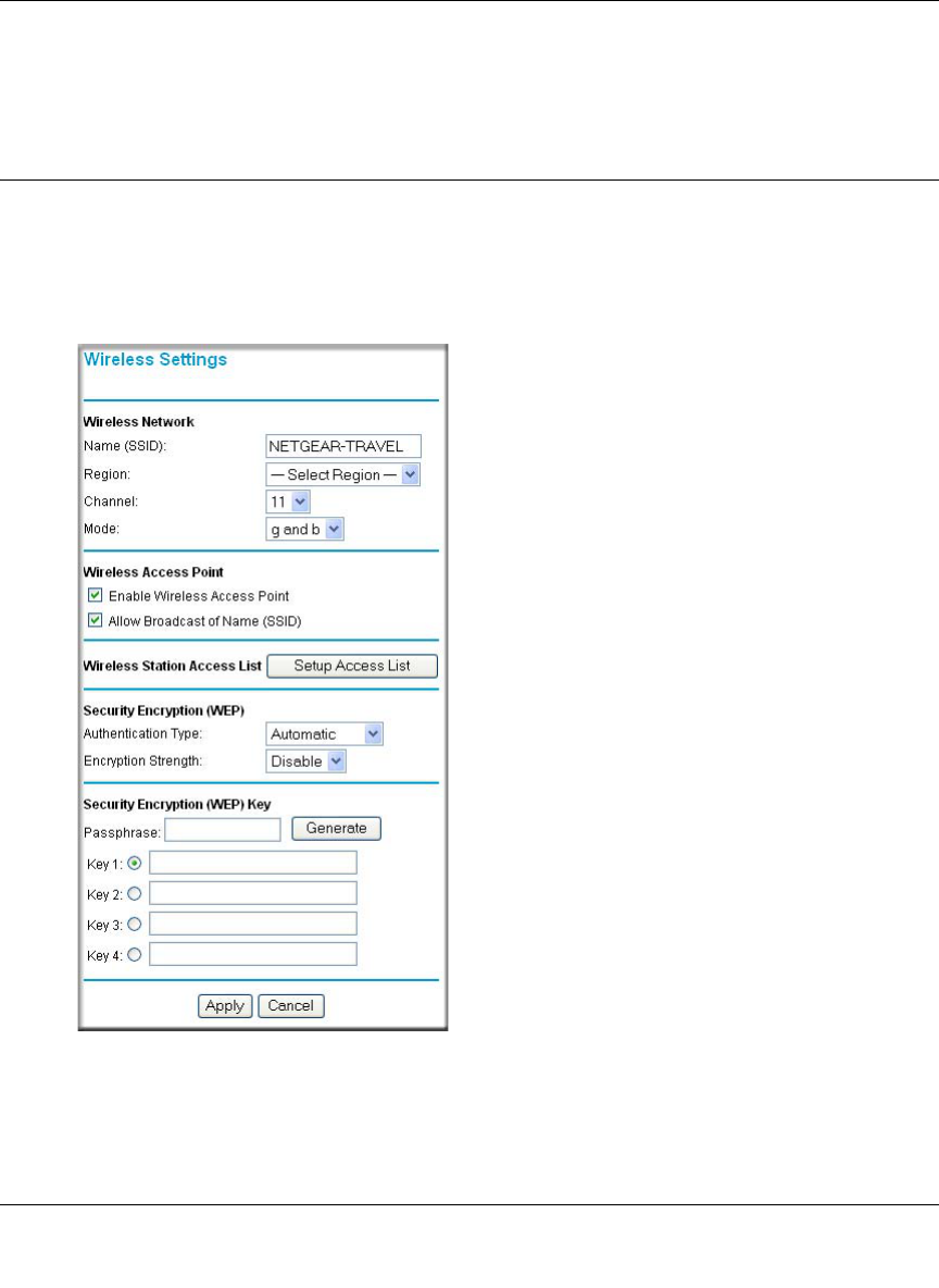
Understanding Wireless Settings
To configure the Wireless settings of your firewall, click the Wireless link in the main menu of the
browser interface. The Wireless Settings menu will appear, as shown below.
Figure 4-2: Wireless Settings page

Reference Manual for the 54 Mbps Wireless Travel Router WGR101
4-4 Wireless Configuration
May 2004 (202-10034-01)
•Name (SSID). The SSID is also known as the wireless network name. Enter a value of up to
32 alphanumeric characters. In a setting where there is more than one wireless network,
different wireless network names provide a means for separating the traffic. Any device you
want to participate in a particular wireless network will need to use this SSID for that network.
The WGR101 default SSID is: NETGEAR.
•Region. This field identifies the region where the WGR101 can be used. It may not be legal to
operate the wireless features of the wireless travel router in a region other than one of those
identified in this field.
•Channel. This field determines which operating frequency will be used. It should not be
necessary to change the wireless channel unless you notice interference problems with another
nearby access point. For more information on the wireless channel frequencies please refer to
“Wireless Channels” on page D-2.
•Mode. This field determines which data communications protocol will be used. You can select
“g only,” “b only,” or “g and b.” “g only” dedicates the WGR101 to communicating with the
higher bandwidth 802.11g wireless devices exclusively. “b only” dedicates the WGR101 to
communicating with the higher bandwidth 802.11b wireless devices exclusively. The “g and
b” mode provides backward compatibility with the slower 802.11b wireless devices while still
enabling 802.11g communications.
•Enable Wireless Access Point. If you disable the wireless access point, wireless devices
cannot connect to the WGR101.
•Allow Broadcast of Name (SSID). If you disable broadcast of the SSID, only devices that
have the correct SSID can connect. Disabling SSID broadcast nullifies the wireless network
‘discovery’ feature of some products such as Windows XP.
•Wireless Station Access List. When the Trusted PCs Only radio button is selected, the
WGR101 checks the MAC address of the wireless station and only allows connections to
computers identified on the trusted computers list.
•Security Encryption. These options are the wireless security features you can enable. The
table below identifies the various basic wireless security options. A full explanation of these
standards is available in Appendix D, “Wireless Networking Basics.

Reference Manual for the 54 Mbps Wireless Travel Router WGR101
Wireless Configuration 4-5
May 2004 (202-10034-01)
Table 4-1. Basic Wireless Security Options
Field Description
Automatic No wireless security.
WEP WEP offers the following options:
• Open System
With Open Network Authentication and 64- or 128-bit WEP Data Encryption, the WGR101
does perform 64- or 128-bit data encryption but does not perform any authentication.
• Shared Key
Shared Key authentication encrypts the SSID and data.
Choose the Encryption Strength (64- or 128-bit data encryption). Manually enter the key
values or enter a word or group of printable characters in the Passphrase box. Manually
entered keys are case sensitive but passphrase characters are not case sensitive.
Note: Not all wireless adapter configuration utilities support passphrase key generation.
•Auto

Reference Manual for the 54 Mbps Wireless Travel Router WGR101
4-6 Wireless Configuration
May 2004 (202-10034-01)
Information to Gather Before Changing Basic Wireless Settings
Before customizing your wireless settings, print this form and record the following information. If
you are working with an existing wireless network, the person who set up or is responsible for the
network will be able to provide this information. Otherwise, you will choose the settings for your
wireless network. Either way, record the settings for your wireless network in the spaces below.
•Wireless Network Name (SSID): ______________________________ The SSID, identifies
the wireless network. You can use up to 32 alphanumeric characters. The SSID is case
sensitive. The SSID in the wireless adapter card must match the SSID of the wireless travel
router. In some configuration utilities (such as in Windows XP), the term “wireless network
name” is used instead of SSID.
•If WEP Authentication is Used. Circle one: Open System, Shared Key, or Auto.
Note: If you select Shared Key, the other devices in the network will not connect unless they
are set to Shared Key as well and are configured with the correct key.
–WEP Encryption key size. Choose one: 64-bit or 128-bit. Again, the encryption key size
must be the same for the wireless adapters and the wireless travel router.
–Data Encryption (WEP) Keys. There are two methods for creating WEP data encryption
keys. Whichever method you use, record the key values in the spaces below.
•Passphrase method. ______________________________ These characters are case
sensitive. Enter a word or group of printable characters and click the Generate Keys
button. Not all wireless devices support the passphrase method.
•Manual method. These values are not case sensitive. For 64-bit WEP, enter 10 hex
digits (any combination of 0-9 or a-f). For 128-bit WEP, enter 26 hex digits.
Key 1: ___________________________________
Key 2: ___________________________________
Key 3: ___________________________________
Key 4: ___________________________________
Use the procedures described in the following sections to configure the WGR101. Store this
information in a safe place.
Reference Manual for the 54 Mbps Wireless Travel Router WGR101
Wireless Configuration 4-7
May 2004 (202-10034-01)
Default Factory Settings
When you first receive your WGR101, the default factory settings are shown below. You can
restore these defaults with the Factory Default Restore button on the rear panel. After you install
the WGR101 wireless travel router, use the procedures below to customize any of the settings to
better meet your networking needs.
How to Set Up and Test Basic Wireless Connectivity
Follow the instructions below to set up and test basic wireless connectivity. Once you have
established basic wireless connectivity, you can enable security settings appropriate to your needs.
1. Log in to the WGR101 firewall at its default LAN address of http://192.168.0.1 with its
default user name of admin and default password of password, or using whatever LAN
address and password you have set up.
2. Click Wireless Settings in the main menu of the WGR101 firewall.
3. Choose a suitable descriptive name for the wireless network name (SSID). In the SSID box,
enter a value of up to 32 alphanumeric characters. The default SSID is NETGEAR.
FEATURE DEFAULT FACTORY SETTINGS
Wireless Access Point Enabled
Wireless Access List (MAC Filtering) All wireless stations allowed
SSID broadcast Enabled
SSID NETGEAR
11b/g RF Channel 11
Mode g and b
Authentication Type Automatic
WEP Disabled
Note: If you use a wireless computer to configure WPA settings, you will be
disconnected when you click Apply. Reconfigure your wireless adapter to match the
new settings or access the wireless travel router from a wired computer to make any
further changes.

Reference Manual for the 54 Mbps Wireless Travel Router WGR101
4-8 Wireless Configuration
May 2004 (202-10034-01)
Note: The SSID is case sensitive; NETGEAR is not the same as nETgear. Also, the SSID of
any wireless access adapters must match the SSID you configure in the 54 Mbps Wireless
Travel Router WGR101 . If they do not match, you will not get a wireless connection to the
WGR101.
4. Set the Region. Select the region in which the wireless interface will operate.
5. Set the Channel. The default channel is 11.
This field determines which operating frequency will be used. It should not be necessary to
change the wireless channel unless you notice interference problems with another nearby
wireless router or access point. Select a channel that is not being used by any other wireless
networks within several hundred feet of your firewall. For more information on the wireless
channel frequencies please refer to “Wireless Channels” on page D-2.
6. For initial configuration and test, leave the Wireless Card Access List set to “Everyone” and
the Encryption Strength set to “Disabled.”
7. Click Apply to save your changes.
8. Configure and test your computers for wireless connectivity.
Program the wireless adapter of your computers to have the same SSID and channel that you
configured in the router. Check that they have a wireless link and are able to obtain an IP
address by DHCP from the firewall.
Warning: The Network Name (SSID) is case sensitive. If NETGEAR is the Network Name
(SSID) in your wireless travel router, you must enter NETGEAR in your computer's wireless
settings. Entering nETgear will not work.
Once your computers have basic wireless connectivity to the firewall, then you can configure the
advanced wireless security functions of the firewall.
How to Configure WEP
To configure WEP data encryption, follow these steps:
Note: If you are configuring the firewall from a wireless computer and you change the
firewall’s SSID, channel, or security settings, you will lose your wireless connection
when you click on Apply. You must then change the wireless settings of your computer
to match the firewall’s new settings.
Reference Manual for the 54 Mbps Wireless Travel Router WGR101
Wireless Configuration 4-9
May 2004 (202-10034-01)
1. Log in to the WGR101 firewall at its default LAN address of http://192.168.0.1 with its
default user name of admin and default password of password, or using whatever LAN
address and password you have set up.
2. Click Wireless Settings in the main menu of the WGR101 firewall.
3. From the Security Options menu, select WEP. The WEP options display.
4. Select the Authentication Type and Encryptions strength from the drop-down lists.
Figure 4-3. Wireless Settings encryption menu
Note: If you use a wireless computer configure WEP settings, you will be disconnected
when you click on Apply. You must then either configure your wireless adapter to match
the wireless travel router WEP settings or access the wireless travel router from a wired
computer to make any further changes.
Reference Manual for the 54 Mbps Wireless Travel Router WGR101
4-10 Wireless Configuration
May 2004 (202-10034-01)
5. You can manually or automatically program the four data encryption keys. These values must
be identical on all computers and Access Points in your network.
• Automatic - Enter a word or group of printable characters in the Passphrase box and click
the Generate button. The passphrase is case sensitive; NETGEAR is not the same as
nETgear. The four key boxes will be automatically populated with key values.
• Manual - Enter ten hexadecimal digits (any combination of 0-9, a-f, or A-F). These entries
are not case sensitive; AA is the same as aa.
Select which of the four keys will be active.
Please refer to “WEP Wireless Security” on page D-4 for a full explanation of each of these
options, as defined by the IEEE 802.11 wireless communication standard.
6. Click Apply to save your settings.
How to Restrict Wireless Access by MAC Address
To restrict access based on MAC Addresses, follow these steps:
1. Log in to the WGR101 firewall at its default LAN address of http://192.168.0.1 with its
default user name of admin and default password of password, or using whatever LAN
address and password you have set up.
2. Click Advanced Wireless Setup in the main menu of the WGR101 firewall.
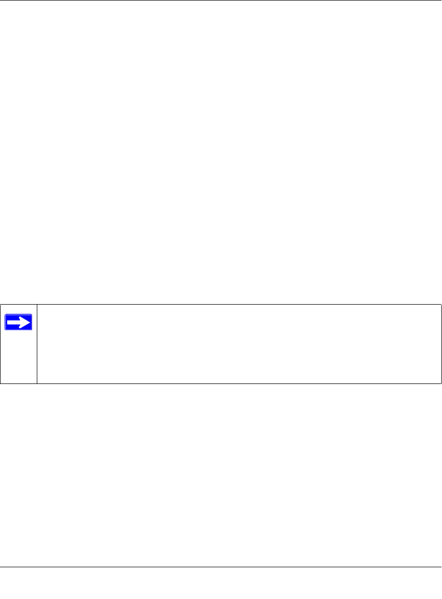
3. From the Wireless Settings menu, click Setup Access List to display the Wireless Access
menu shown below.
Note: When configuring the firewall from a wireless computer whose MAC address is
not in the Trusted PC list, if you select Turn Access Control On, you will lose your
wireless connection when you click on Apply. You must then access the wireless travel
router from a wired computer or from a wireless computer which is on the access control
list to make any further changes.
Reference Manual for the 54 Mbps Wireless Travel Router WGR101
Wireless Configuration 4-11
May 2004 (202-10034-01)
Figure 4-4: Wireless Card Access List Setup
4. Click Add to add a wireless device to the wireless access control list. The Available Wireless
Cards list displays.
5. Click the Turn Access Control On check box.
6. Then, either select from the list of available wireless cards the WGR101 has found in your
area, or enter the MAC address and device name for a device you plan to use. You can usually
find the MAC address printed on the wireless adapter.
Note: You can copy and paste the MAC addresses from the firewall’s Attached Devices menu
into the MAC Address box of this menu. To do this, configure each wireless computer to
obtain a wireless link to the firewall. The computer should then appear in the Attached
Devices menu.
7. Click Add to add this wireless device to the Wireless Card Access List. The screen changes
back to the list screen. Repeat these steps for each additional device you wish to add to the list.
8. Be sure to click Apply to save your wireless access control list settings.
Now, only devices on this list will be allowed to wirelessly connect to the WGR101.

Reference Manual for the 54 Mbps Wireless Travel Router WGR101
4-12 Wireless Configuration
May 2004 (202-10034-01)
Management 5-1
May 2004 (202-10034-01)
Chapter 5
Management
This chapter describes how to use the maintenance features of your 54 Mbps Wireless Travel
Router WGR101 . Set the Travel Router switch to position 2 or position 3. Then you can click the
Maintenance heading in the Main Menu of the browser interface to open the Router Status page.
Viewing Wireless Travel Router Status Information
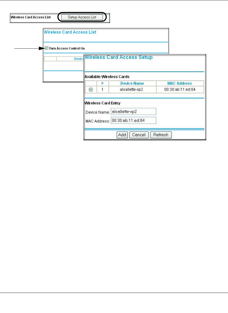
The Router Status menu provides a limited amount of status and usage information. From the
Main Menu of the browser interface, click on Maintenance, then select System Status to view the
System Status screen, shown below.
Figure 5-1: Router Status screen

Reference Manual for the 54 Mbps Wireless Travel Router WGR101
5-2 Management
May 2004 (202-10034-01)
This screen shows the following parameters:
Table 5-1. Menu 3.2 - Wireless Travel Router Status Fields
Field Description
Account Name This field displays the Host Name assigned to the router.
Firmware Version This field displays the router firmware version.
Internet Port These parameters apply to the Internet (WAN) port of the router.
MAC Address This field displays the Media Access Control address being used by the
Internet (WAN) port of the router.
IP Address This field displays the IP address being used by the Internet (WAN) port
of the router. If no address is shown, the router cannot connect to the
Internet.
IP Subnet Mask This field displays the IP Subnet Mask being used by the Internet (WAN)
port of the router.
DHCP If set to None, the router is configured to use a fixed IP address on the
WAN.
If set to Client, the router is configured to obtain an IP address
dynamically from the ISP.
LAN Port These parameters apply to the Local (WAN) port of the router.
MAC Address This field displays the Media Access Control address being used by the
LAN port of the router.
IP Address This field displays the IP address being used by the Local (LAN) port of
the router. The default is 192.168.0.1
DHCP Identifies if the router’s built-in DHCP server is active for the LAN
attached devices.
IP Subnet Mask This field displays the IP Subnet Mask being used by the Local (LAN)
port of the router. The default is 255.255.255.0
Wireless Port These parameters apply to the Wireless port of the router.
MAC Address This field displays the Media Access Control address being used by the
Wireless port of the router.
Name (SSID) This field displays the wireless network name (SSID) being used by the
wireless port of the router. The default is Wireless.
Region This field displays the geographic region where the router being used. It
may be illegal to use the wireless features of the router in some parts of
the world.
Channel Identifies if the channel the wireless port is using. See “Wireless
Channels” on page D-2 for the frequencies used on each channel.
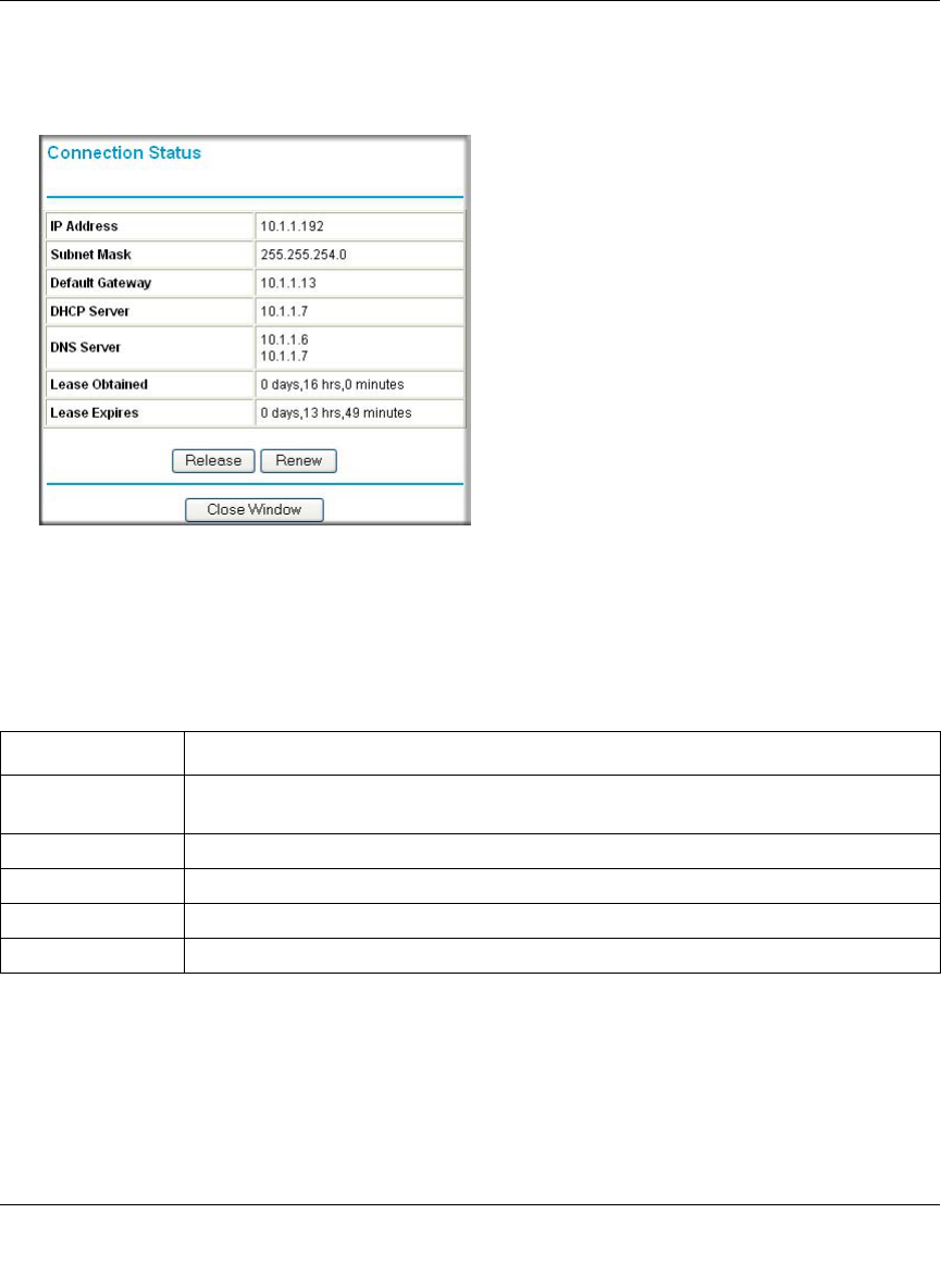
Reference Manual for the 54 Mbps Wireless Travel Router WGR101
Management 5-3
May 2004 (202-10034-01)
Click on the “Show WAN Status” button to display the WAN status, as shown below.
Figure 5-2: Connection Status screen
This screen shows the following statistics:.
Table 5-1. Connection Status Fields
Field Description
Connection Time The length of time the router has been connected to your Internet service provider’s
network.
Connection Method The method used to obtain an IP address from your Internet service provider.
IP Address The WAN (Internet) IP Address assigned to the router.
Network Mask The WAN (Internet) Subnet Mask assigned to the router.
Default Gateway The WAN (Internet) default gateway the router communicates with.
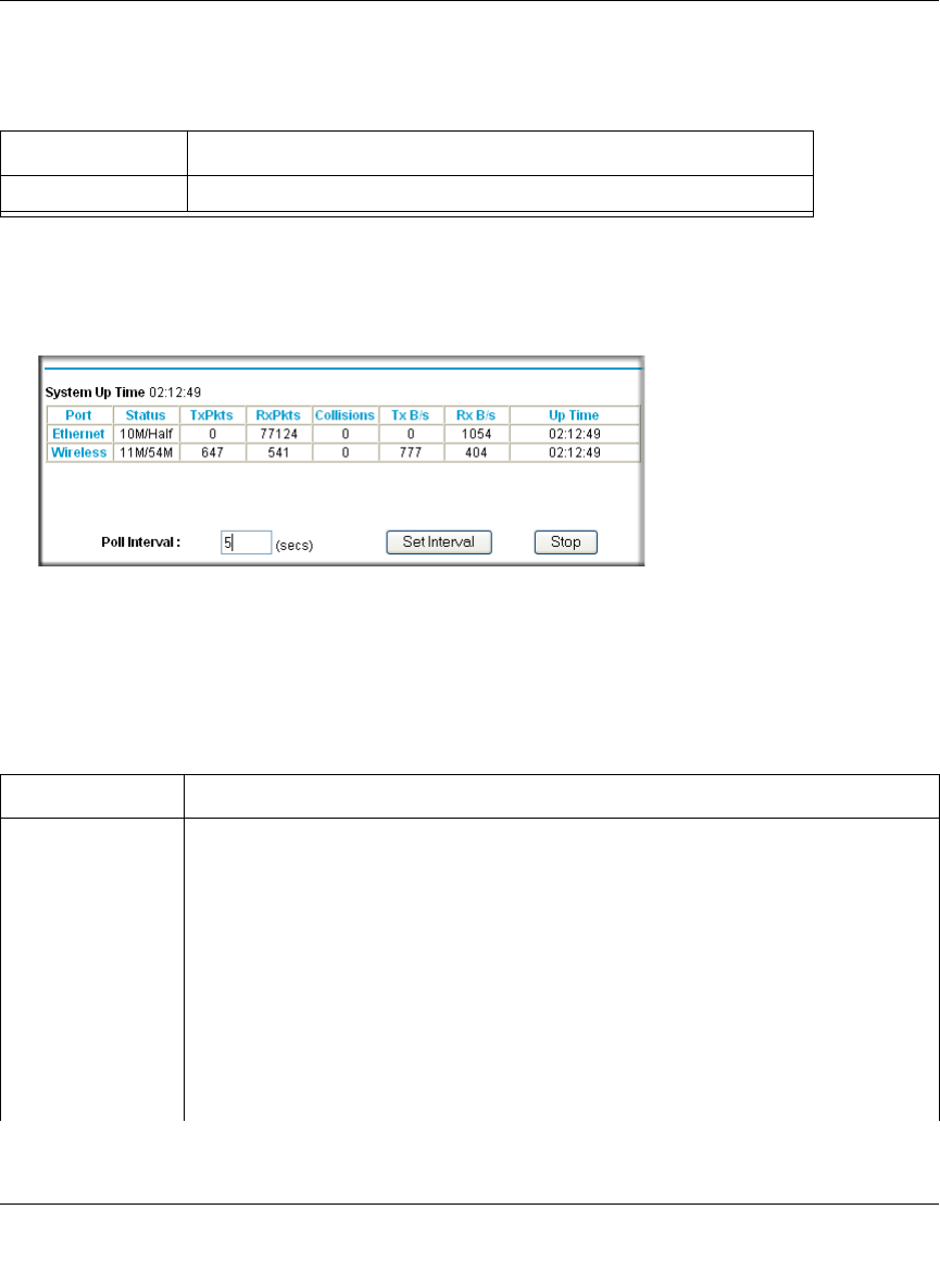
Reference Manual for the 54 Mbps Wireless Travel Router WGR101
5-4 Management
May 2004 (202-10034-01)
WAN Status action buttons are described in Table 5-2
Click on the “Show Statistics” button to display router usage statistics, as shown below.
Figure 5-3: Router Statistics screen
This screen shows the following statistics:
Table 5-2. Show WAN Status action buttons
Field Description
Renew Click the Renew button to renew the DHCP lease.
Table 5-1. Router Statistics Fields
Field Description
Port The statistics for the WAN (Internet) and LAN (local) ports. For each port, the screen
displays:
Status The link status of the port.
TxPkts The number of packets transmitted on this port since reset or manual clear.
RxPkts The number of packets received on this port since reset or manual clear.
Collisions The number of collisions on this port since reset or manual clear.
Tx B/s The current transmission (outbound) bandwidth used on the WAN and LAN ports.
Rx B/s The current reception (inbound) bandwidth used on the WAN and LAN ports.
Up Time The amount of time since the router was last restarted.
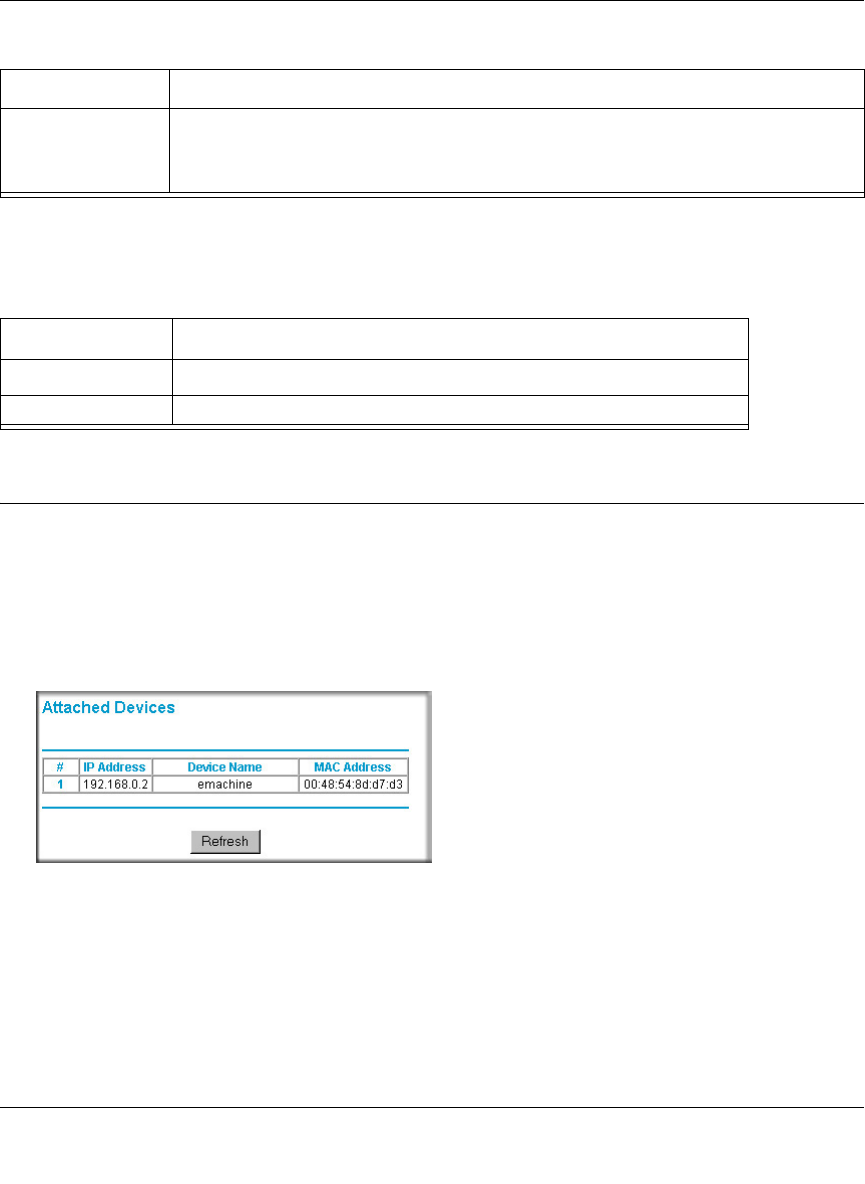
Reference Manual for the 54 Mbps Wireless Travel Router WGR101
Management 5-5
May 2004 (202-10034-01)
Show Statistics action buttons are described in Table 5-2
Viewing a List of Attached Devices
The Attached Devices menu contains a table of all IP devices that the router has discovered on the
local network. From the Main Menu of the browser interface, under the Maintenance heading,
select Attached Devices to view the table, shown below.
Figure 5-4: Attached Devices menu
For each device, the table shows the IP address, NetBIOS Host Name (if available), and Ethernet
MAC address. Note that if the router is rebooted, the table data is lost until the router rediscovers
the devices. To force the router to look for attached devices, click the Refresh button.
Up Time The time elapsed since this port acquired the link.
Poll Interval Specifies the intervals at which the statistics are updated in this window. Click on Stop
to freeze the display.
Table 5-2. Show Statistics action buttons
Field Description
Set Interval Enter a time and click the button to set the polling frequency.
Stop Click the Stop button to freeze the polling information.
Table 5-1. Router Statistics Fields (continued)
Field Description
Reference Manual for the 54 Mbps Wireless Travel Router WGR101
5-6 Management
May 2004 (202-10034-01)
Upgrading the Router Software
The routing software of the WGR101 wireless travel router is stored in FLASH memory, and can
be upgraded as new software is released by NETGEAR.
Note: The web browser used to upload new firmware into the WGR101 wireless travel router must
support HTTP uploads. Use Microsoft Internet Explorer or Netscape Navigator 4.0 or above. Do
not interrupt the upgrade process once it has started.
From the Main Menu of the browser interface, under the Maintenance heading, select the Router
Upgrade heading to display the menu shown below.
Note: When uploading software to the WGR101 wireless travel router, it is important not to
interrupt the Web browser by closing the window, clicking a link, or loading a new page. If the
browser is interrupted, it may corrupt the software. When the upload is complete, your router will
automatically restart. The upgrade process will typically take about one minute.
To check for new firmware:
1. Click Check.If the WGR101 finds new firmware is available, follow the on-screen prompts to
download in install the new firmware.
To upload firmware from your hard drive:
1. In the Router Upgrade menu, click the Browse button and browse to the location of the binary
(.BIN) upgrade file.
2. Click Upload.
In some cases, you may need to reconfigure the router after upgrading.
Configuration File Management
The configuration settings of the WGR101 wireless travel router are stored within the router in a
configuration file. This file can be saved (backed up) to a user’s computer, retrieved (restored)
from the user’s computer, or cleared to factory default settings.
Note: Be sure to check the NETGEAR web site for documentation updates which are
available at http://www.netgear.com/docs.
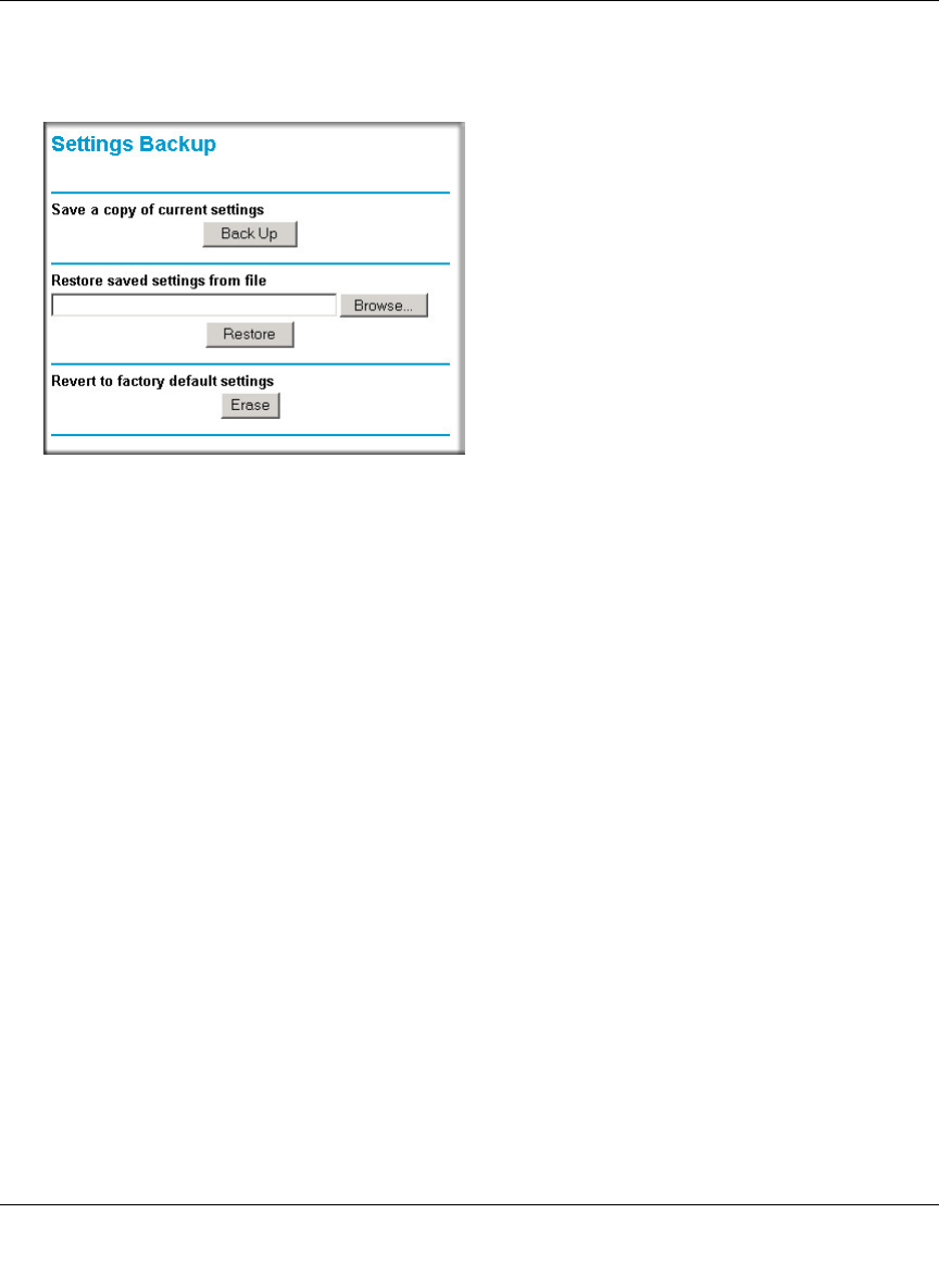
Reference Manual for the 54 Mbps Wireless Travel Router WGR101
Management 5-7
May 2004 (202-10034-01)
From the Main Menu of the browser interface, under the Maintenance heading, select the Settings
Backup heading to bring up the menu shown below.
Figure 5-5: Settings Backup menu
Three options are available, and are described in the following sections.
Restoring and Backing Up the Configuration
The Restore and Backup options in the Settings Backup menu allow you to save and retrieve a file
containing your router’s configuration settings.
To save your settings, select the Backup tab. Click the Backup button. Your browser will extract
the configuration file from the router and will prompt you for a location on your computer to store
the file. You can give the file a meaningful name at this time, such as pacbell.cfg.
To restore your settings from a saved configuration file, enter the full path to the file on your
computer or click the Browse button to browse to the file. When you have located it, click the
Restore button to send the file to the router. The router will then reboot automatically.
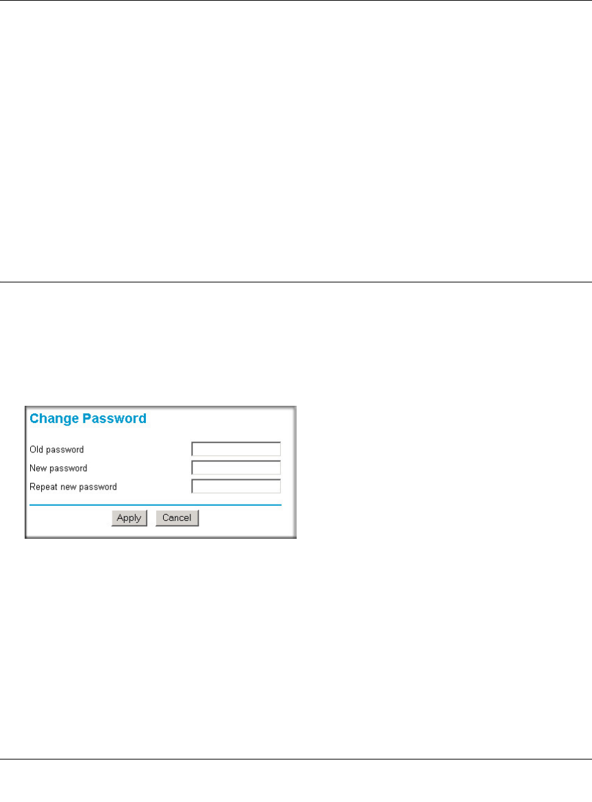
Reference Manual for the 54 Mbps Wireless Travel Router WGR101
5-8 Management
May 2004 (202-10034-01)
Erasing the Configuration
It is sometimes desirable to restore the router to the factory default settings. This can be done by
using the Erase function, which will restore all factory settings. After an erase, the router's
password will be password, the LAN IP address will be 192.168.0.1, and the router's DHCP client
will be enabled.
To erase the configuration, click the Erase button.
To restore the factory default configuration settings without knowing the login password or IP
address, you must use the Default Reset button on the rear panel of the router. See “Restoring the
Default Configuration and Password” on page 7-5.
Changing the Administrator Password
The default password for the router’s web Configuration Manager is password. Netgear
recommends that you change this password to a more secure password.
From the Main Menu of the browser interface, under the Maintenance heading, select Set
Password to bring up the menu shown below.
Figure 5-6: Set Password menu
To change the password, first enter the old password, and then enter the new password twice. Click
Apply.
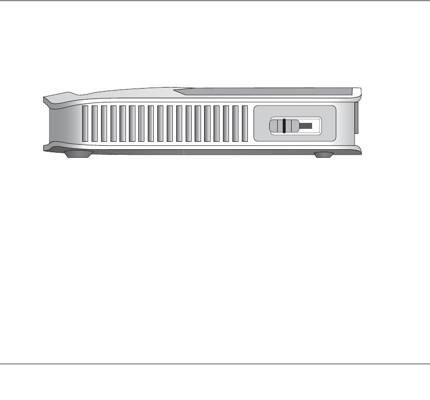
Network Configuration 6-1
May 2004 (202-10034-01)
Chapter 6
Network Configuration
This chapter describes how to configure the advanced features of your 54 Mbps Wireless Travel
Router WGR101 . If the WGR101 switch is set at position 2 for multiple users, or position 3 for
configuration, you can access this feature. It can be found under the Advanced heading in the Main
Menu of the browser interface.
Wireless Login to the Wireless Travel Router
When you want to customize the network settings of your wireless travel router, when in
multi-user mode (switch position 3), you can wirelessly connect to the router to change its settings.
Follow these procedures to log in to the wireless travel router.
Figure 6-1: Switch position 2
1. Set the switch to position 2.
Note: This procedure will work with the switch in position 3 as well. However, the login
process will lead to the Basic Settings page when the switch is in position 2 rather leading to
the Wireless Settings page when the switch is in position 3. In either case, you have full access
to all the configuration pages in the wireless travel router.
2. Connect the power cord to the wireless travel router and plug it into an outlet. The Power LED
lights up.
Check the status lights and verify the following:
3WITCHINPOSITION
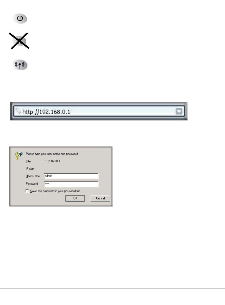
Reference Manual for the 54 Mbps Wireless Travel Router WGR101
6-2 Network Configuration
May 2004 (202-10034-01)
Power: When you first turn on the router, the power light blinks during the
diagnostic self test, then turns solid green.
Ethernet: The Ethernet port light on the wireless travel router will off.
Wireless: The Wireless light should be lit. If the Wireless light is not lit, see the
Basic Setup Troubleshooting Tips below.
3. From a wireless computer, open a Web browser such as Internet Explorer.
4. Type http://192.168.0.1 in the address field of your browser, then click Enter.
Figure 6-2: WGR101 wireless travel router default login address
A login window like the one shown below opens:
Figure 6-3: Login window
When prompted, enter admin for the router user name and password for the router password,
both in lower case letters.
The WGR101 wireless travel router and display the home page as shown in below.
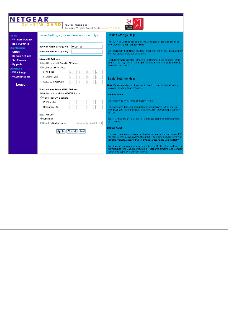
Reference Manual for the 54 Mbps Wireless Travel Router WGR101
Network Configuration 6-3
May 2004 (202-10034-01)
Figure 6-4: Switch position 2 login result: WGR101 basic settings page
The browser will then display the WGR101 basic settings page.
You can set the wireless security options on this page. For instructions on setting the wireless
settings, see “Network Configuration” on page 6-1.
If you do not click Logout, the wireless travel router will wait 5 minutes after there is no
activity before it automatically logs you out.
Configuring Basic Settings Options
The Basic Settings options let you configure the IP address information the wireless travel router
will use. For example, some hotels may require you to use a static IP address, which you would
have to configure using this screen. These options are discussed below.
1. Log in and click Basic Settings link in the Setup menu.
2. If your Internet connection does not require a login, fill in the settings according to the
instructions below.

Reference Manual for the 54 Mbps Wireless Travel Router WGR101
6-4 Network Configuration
May 2004 (202-10034-01)
a. Enter your Account Name (may also be called Host Name) and Domain Name.
These parameters may be necessary to access your ISP’s services such as mail or news
servers.
b. Internet IP Address:
If your ISP has assigned you a permanent, fixed (static) IP address for your computer,
select “Use static IP address”. Enter the IP address that your ISP assigned. Also enter the
netmask and the Gateway IP address. The Gateway is the ISP’s router to which your router
will connect.
c. Domain Name Server (DNS) Address:
If you know that your ISP does not automatically transmit DNS addresses to the router
during login, select “Use these DNS servers” and enter the IP address of your ISP’s
Primary DNS Server. If a Secondary DNS Server address is available, enter it also.
Note: If you enter an address here, restart the computers on your network so that these
settings take effect.
d. MAC Address:
This section determines the Ethernet MAC address that will be used by the router on the
Internet port. Some ISPs will register the Ethernet MAC address of the network interface
card in your computer when your account is first opened. They will then only accept
traffic from the MAC address of that computer. This feature allows your router to
masquerade as that computer by “cloning” its MAC address.
To change the MAC address, select “Use this MAC address” and enter it.
e. Click Apply to save your settings.
Configuring WAN Setup Options
The WAN Setup options let you configure a DMZ server and enable the wireless travel router to
respond to a Ping on the WAN port. These options are discussed below.
Setting Up a Default DMZ Server
The default DMZ server feature is helpful when using some online games and
videoconferencing applications that are incompatible with NAT. The router is programmed to
recognize some of these applications and to work properly with them, but there are other
applications that may not function well. In some cases, one local computer can run the
application properly if that computer’s IP address is entered as the default DMZ server.

Reference Manual for the 54 Mbps Wireless Travel Router WGR101
Network Configuration 6-5
May 2004 (202-10034-01)
Incoming traffic from the Internet is normally discarded by the router unless the traffic is a
response to one of your local computers or a service that you have configured in the Ports menu.
Instead of discarding this traffic, you can have it forwarded to one computer on your network. This
computer is called the Default DMZ Server.
The WAN Setup menu, shown below lets you configure a Default DMZ Server.
To assign a computer or server to be a Default DMZ server, follow these steps:
1. Click WAN Setup on the Advanced section of the main menu.
2. Type the IP address for that server. To remove the default DMZ server, replace the IP address
numbers with all zeros.
3. Click Apply to save your settings.
Respond to Ping on Internet WAN Port
If you want the router to respond to a 'ping' from the Internet, click the ‘Respond to Ping on
Internet WAN Port’ check box. This should only be used as a diagnostic tool, since it allows your
router to be discovered. Don't check this box unless you have a specific reason to do so.
Any packets sent through the router that are larger than the configured MTU size will be
repackaged into smaller packets to meet the MTU requirement. To change the MTU size:
Under MTU Size, enter a new size between 64 and 1500. Then, click Apply to save the new
configuration.
Note: DMZ servers pose a security risk. A computer designated as the default DMZ
server loses much of the protection of the firewall, and is exposed to exploits from the
Internet. If compromised, the DMZ server can be used to attack your network.
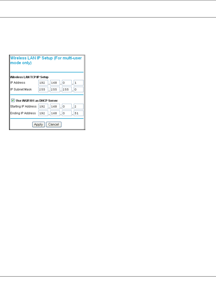
Reference Manual for the 54 Mbps Wireless Travel Router WGR101
6-6 Network Configuration
May 2004 (202-10034-01)
Using WAN IP Setup Options
The LAN IP Setup feature is under the Advanced heading of the main menu. This feature allows
configuration of LAN IP services such as DHCP and RIP. From the Main Menu of the browser
interface, under Advanced, click on LAN IP Setup to view the LAN IP Setup menu, shown below.
Figure 6-5: LAN IP Setup Menu
The router is shipped preconfigured to use private IP addresses on the LAN side, and to act as a
DHCP server. The router’s default LAN IP configuration is:
• LAN IP addresses—192.168.0.1
• Subnet mask—255.255.255.0
These addresses are part of the IETF-designated private address range for use in private networks,
and should be suitable in most applications. If your network has a requirement to use a different IP
addressing scheme, you can make those changes in this menu.
The LAN IP parameters are:
• IP Address
This is the LAN IP address of the router.
• IP Subnet Mask
This is the LAN Subnet Mask of the router. Combined with the IP address, the IP Subnet Mask
allows a device to know which other addresses are local to it, and which must be reached
through a gateway or router.
Reference Manual for the 54 Mbps Wireless Travel Router WGR101
Network Configuration 6-7
May 2004 (202-10034-01)
• RIP Direction
RIP (Router Information Protocol) allows a router to exchange routing information with other
routers. The RIP Direction selection controls how the router sends and receives RIP packets.
Both is the default.
— When set to Both or Out Only, the router will broadcast its routing table periodically.
— When set to Both or In Only, it will incorporate the RIP information that it receives.
— When set to None, it will not send any RIP packets and will ignore any RIP packets
received.
• RIP Version
This controls the format and the broadcasting method of the RIP packets that the router sends.
(It recognizes both formats when receiving.) By default, this is set for RIP-1.
— RIP-1 is universally supported. RIP-1 is probably adequate for most networks, unless you
have an unusual network setup.
— RIP-2 carries more information. RIP-2B uses subnet broadcasting.
Using the Router as a DHCP server
By default, the router will function as a DHCP (Dynamic Host Configuration Protocol) server,
allowing it to assign IP, DNS server, and default gateway addresses to all computers connected to
the router's LAN. The assigned default gateway address is the LAN address of the router. IP
addresses will be assigned to the attached computers from a pool of addresses specified in this
menu. Each pool address is tested before it is assigned to avoid duplicate addresses on the LAN.
For most applications, the default DHCP and TCP/IP settings of the router are satisfactory. See “IP
Configuration by DHCP” on page B-10 for an explanation of DHCP and information about how to
assign IP addresses for your network.
If another device on your network will be the DHCP server, or if you will manually configure the
network settings of all of your computers, clear the ‘Use router as DHCP server’ check box.
Otherwise, leave it checked.
Note: If you change the LAN IP address of the router while connected through the
browser, you will be disconnected. You may need to restart your computer for the new IP
address setting to take effect.

Reference Manual for the 54 Mbps Wireless Travel Router WGR101
6-8 Network Configuration
May 2004 (202-10034-01)
Specify the pool of IP addresses to be assigned by setting the Starting IP Address and Ending IP
Address. These addresses should be part of the same IP address subnet as the router’s LAN IP
address. Using the default addressing scheme, you should define a range between 192.168.0.2 and
192.168.0.253, although you may wish to save part of the range for devices with fixed addresses.
The router will deliver the following parameters to any LAN device that requests DHCP:
• An IP Address from the range you have defined
• Subnet Mask
• Gateway IP Address (the router’s LAN IP address)
• Primary DNS Server (if you entered a Primary DNS address in the Basic Settings menu;
otherwise, the router’s LAN IP address)
• Secondary DNS Server (if you entered a Secondary DNS address in the Basic Settings menu

Troubleshooting 7-1
May 2004 (202-10034-01)
Chapter 7
Troubleshooting
This chapter gives information about troubleshooting your 54 Mbps Wireless Travel Router
WGR101 . After each problem description, instructions are provided to help you diagnose and
solve the problem.
Basic Functioning
After you turn on power to the router, the following sequence of events should occur:
1. When power is first applied, verify that the Power light is on.
2. After approximately 10 seconds, verify that:
a. The power light is solid green.
b. The LAN port lights are lit for any local ports that are connected.
c. The Internet port light is lit.
If a port’s light is lit, a link has been established to the connected device. If a LAN port is
connected to a 100 Mbps device, verify that the port’s light is green. If the port is 10 Mbps, the
light will be amber.
If any of these conditions does not occur, refer to the appropriate following section.
Power Light Not On
If the Power and other lights are off when your router is turned on:
• Make sure that the power cord is properly connected to your router and that the power supply
adapter is properly connected to a functioning power outlet.
• Check that you are using the 5 V DC 2A power adapter supplied by NETGEAR for this
product.
If the error persists, you have a hardware problem and should contact technical support.

Reference Manual for the 54 Mbps Wireless Travel Router WGR101
7-2 Troubleshooting
May 2004 (202-10034-01)
Lights Never Turn Off
When the router is turned on, the lights turns on for about 10 seconds and then turn off. If all the
lights stay on, there is a fault within the router.
If all lights are still on one minute after power up:
• Cycle the power to see if the router recovers.
• Clear the router’s configuration to factory defaults. This will set the router’s IP address to
192.168.0.1. This procedure is explained in “Restoring the Default Configuration and
Password” on page 7-5.
If the error persists, you might have a hardware problem and should contact technical support.
LAN/ WAN Port Light Not On
If this light does not light when the Ethernet connection is made, check the following:
• Make sure that the Ethernet cable connections are secure at the router and at the RJ45 slot, or
router, or cable modem.
• Make sure that power is turned on to the connected hub or workstation.
• Be sure you are using the correct cable:
— When connecting the router’s Internet port to a cable modem, use the cable that was
supplied with the cable modem. This cable could be a standard straight-through Ethernet
cable or an Ethernet crossover cable.

Reference Manual for the 54 Mbps Wireless Travel Router WGR101
Troubleshooting 7-3
May 2004 (202-10034-01)
Troubleshooting the Web Configuration Interface
If you are unable to access the router’s web Configuration interface from a computer on your local
network, check the following:
• Check the Ethernet connection between the computer and the router as described in the
previous section.
• Make sure your computer’s IP address is on the same subnet as the router. If you are using the
recommended addressing scheme, your computer’s address should be in the range of
192.168.0.2 to 192.168.0.254. Refer to “Verifying TCP/IP Properties” on page C-6 or
“Verifying TCP/IP Properties for Macintosh Computers” on page C-17 to find your
computer’s IP address. Follow the instructions in Appendix C to configure your computer.
Note: If your computer’s IP address is shown as 169.254.x.x: Recent versions of Windows
and MacOS will generate and assign an IP address if the computer cannot reach a DHCP
server. These auto-generated addresses are in the range of 169.254.x.x. If your IP address is in
this range, check the connection from the computer to the router and reboot your computer.
• If your router’s IP address has been changed and you don’t know the current IP address, clear
the router’s configuration to factory defaults. This will set the router’s IP address to
192.168.0.1. This procedure is explained in “Restoring the Default Configuration and
Password” on page 7-5.
• Make sure your browser has Java, JavaScript, or ActiveX enabled. If you are using Internet
Explorer, click Refresh to be sure the Java applet is loaded.
• Try quitting the browser and launching it again.
• Make sure you are using the correct login information. The factory default login name is
admin and the password is password. Make sure that CAPS LOCK is off when entering this
information.
If the router does not save changes you have made in the web Configuration Interface, check the
following:
• When entering configuration settings, be sure to click the APPLY button before moving to
another menu or tab, or your changes are lost.
• Click the Refresh or Reload button in the web browser. The changes may have occurred, but
the web browser may be caching the old configuration.

Reference Manual for the 54 Mbps Wireless Travel Router WGR101
7-4 Troubleshooting
May 2004 (202-10034-01)
Troubleshooting a TCP/IP Network Using a Ping Utility
Most TCP/IP terminal devices and routers contain a ping utility that sends an echo request packet
to the designated device. The device then responds with an echo reply. Troubleshooting a TCP/IP
network is made very easy by using the ping utility in your computer or workstation.
Testing the LAN Path to Your Router
You can ping the router from your computer to verify that the LAN path to your router is set up
correctly.
To ping the router from a PC running Windows 95 or later:
1. From the Windows toolbar, click on the Start button and select Run.
2. In the field provided, type Ping followed by the IP address of the router, as in this example:
ping 192.168.0.1
3. Click on OK.
You should see a message like this one:
Pinging <IP address> with 32 bytes of data
If the path is working, you see this message:
Reply from < IP address >: bytes=32 time=NN ms TTL=xxx
If the path is not working, you see this message:
Request timed out
If the path is not functioning correctly, you could have one of the following problems:
• Wrong physical connections
— Make sure the LAN port LED is on. If the LED is off, follow the instructions in
“LAN/ WAN Port Light Not On” on page 7-2.
— Check that the corresponding Link LEDs are on for your network interface card and
for the hub ports (if any) that are connected to your workstation and router.
• Wrong network configuration
— Verify that the Ethernet card driver software and TCP/IP software are both installed
and configured on your computer or workstation.

Reference Manual for the 54 Mbps Wireless Travel Router WGR101
Troubleshooting 7-5
May 2004 (202-10034-01)
— Verify that the IP address for your router and your workstation are correct and that the
addresses are on the same subnet.
Testing the Path from Your Computer to a Remote Device
After verifying that the LAN path works correctly, test the path from your computer to a remote
device. From the Windows run menu, type:
PING -n 10 <IP address>
where <IP address> is the IP address of a remote device such as your ISP’s DNS server.
If the path is functioning correctly, replies as in the previous section are displayed. If you do not
receive replies:
— Check that your computer has the IP address of your router listed as the default gateway. If
the IP configuration of your computer is assigned by DHCP, this information will not be
visible in your computer’s Network Control Panel. Verify that the IP address of the router
is listed as the default gateway as described in “Verifying TCP/IP Properties” on page C-6.
— Check to see that the network address of your computer (the portion of the IP address
specified by the netmask) is different from the network address of the remote device.
— Check that your cable or DSL modem is connected and functioning.
— If your ISP assigned a host name to your computer, enter that host name as the Account
Name in the Basic Settings menu.
— Your ISP could be rejecting the Ethernet MAC addresses of all but one of your computers.
Many broadband ISPs restrict access by only allowing traffic from the MAC address of
your broadband modem, but some ISPs additionally restrict access to the MAC address of
a single computer connected to that modem. If this is the case, you must configure your
router to “clone” or “spoof” the MAC address from the authorized computer. Refer to
“Configuring Basic Settings Options” on page 6-3.
Restoring the Default Configuration and Password
This section explains how to restore the factory default configuration settings, changing the
router’s administration password to password and the IP address to 192.168.0.1. You can erase the
current configuration and restore factory defaults in two ways:
• Use the Erase function of the router (see “Erasing the Configuration” on page 5-8).

Reference Manual for the 54 Mbps Wireless Travel Router WGR101
7-6 Troubleshooting
May 2004 (202-10034-01)
• Use the Default Reset button on the rear panel of the router. Use this method for cases when
the administration password or IP address is not known.
To restore the factory default configuration settings without knowing the administration password
or IP address, you must use the Default Reset button on the rear panel of the router.
1. Press and hold the Default Reset button until the power light blinks on (about 10 seconds).
2. Release the Default Reset button and wait for the router to reboot.
If the wireless travel router fails to restart or the power light continues to blink or turns solid
amber, the unit may be defective. If the error persists, you might have a hardware problem and
should contact technical support.

Technical Specifications A-1
May 2004 (202-10034-01)
Appendix A
Technical Specifications
This appendix provides technical specifications for the 54 Mbps Wireless Travel Router WGR101
.
Network Protocol and Standards Compatibility
Data and Routing Protocols: TCP/IP, DHCP
Power Adapter
North America: 120V, 60 Hz, input
United Kingdom, Australia: 240V, 50 Hz, input
Europe: 230V, 50 Hz, input
Japan: 100V, 50/60 Hz, input
All regions (output): 5 V DC @ 2A output, 7W maximum
Physical Specifications
Dimensions: 28 x 175 x 118 mm (1.1 x 6.89 x 4.65 in.)
Weight: 0.3 kg (0.66 lb)
Environmental Specifications
Operating temperature: 0° to 40° C (32º to 104º F)
Operating humidity: 90% maximum relative humidity, noncondensing
Electromagnetic Emissions
Meets requirements of: FCC Part 15 Class B
VCCI Class B
EN 55 022 (CISPR 22), Class B
Interface Specifications
LAN: 10BASE-T or 100BASE-Tx, RJ-45
WAN: 10BASE-T, RJ-45

Reference Manual for the 54 Mbps Wireless Travel Router WGR101
A-2 Technical Specifications
May 2004 (202-10034-01)
Wireless
Radio Data Rates 1, 2, 5.5, 6, 9, 12, 18, 24, 36, 48, and 54 Mbps
Auto Rate Sensing
Frequency 2.4-2.5Ghz
Data Encoding: 802.11b: Direct Sequence Spread Spectrum (DSSS)
802.11g: Orthogonal Frequency Division Multiplexing
(OFDM)
Maximum Computers Per
Wireless Network: Limited by the amount of wireless network traffic generated
by each node. Typically 30-70 nodes.
Operating Frequency Ranges: 2.412~2.462 GHz (US) 2.457~2.462 GHz (Spain)
2.412~2.484 GHz (Japan) 2.457~2.472 GHz (France)
2.412~2.472 GHz (Europe ETSI)
802.11 Security: 40-bits (also called 64-bits) and 128-bits WEP

Network, Routing, Firewall, and Basics B-1
May 2004 (202-10034-01)
Appendix B
Network, Routing, Firewall, and Basics
This chapter provides an overview of IP networks, routing, and networking.
Related Publications
As you read this document, you may be directed to various RFC documents for further
information. An RFC is a Request For Comment (RFC) published by the Internet Engineering
Task Force (IETF), an open organization that defines the architecture and operation of the Internet.
The RFC documents outline and define the standard protocols and procedures for the Internet. The
documents are listed on the World Wide Web at www.ietf.org and are mirrored and indexed at
many other sites worldwide.
Basic Router Concepts
Large amounts of bandwidth can be provided easily and relatively inexpensively in a local area
network (LAN). However, providing high bandwidth between a local network and the Internet can
be very expensive. Because of this expense, Internet access is usually provided by a slower-speed
wide-area network (WAN) link such as a cable or DSL modem. In order to make the best use of the
slower WAN link, a mechanism must be in place for selecting and transmitting only the data traffic
meant for the Internet. The function of selecting and forwarding this data is performed by a router.
What is a Router?
A router is a device that forwards traffic between networks based on network layer information in
the data and on routing tables maintained by the router. In these routing tables, a router builds up a
logical picture of the overall network by gathering and exchanging information with other routers
in the network. Using this information, the router chooses the best path for forwarding network
traffic.
Routers vary in performance and scale, number of routing protocols supported, and types of
physical WAN connection they support. The 54 Mbps Wireless Travel Router WGR101 is a small
office router that routes the IP protocol over a single-user broadband connection.

Reference Manual for the 54 Mbps Wireless Travel Router WGR101
B-2 Network, Routing, Firewall, and Basics
May 2004 (202-10034-01)
Routing Information Protocol
One of the protocols used by a router to build and maintain a picture of the network is the Routing
Information Protocol (RIP). Using RIP, routers periodically update one another and check for
changes to add to the routing table.
The WGR101 wireless travel router supports both the older RIP-1 and the newer RIP-2 protocols.
Among other improvements, RIP-2 supports subnet and multicast protocols. RIP is not required
for most home applications.
IP Addresses and the Internet
Because TCP/IP networks are interconnected across the world, every machine on the Internet must
have a unique address to make sure that transmitted data reaches the correct destination. Blocks of
addresses are assigned to organizations by the Internet Assigned Numbers Authority (IANA).
Individual users and small organizations may obtain their addresses either from the IANA or from
an Internet service provider (ISP). You can contact IANA at www.iana.org.
The Internet Protocol (IP) uses a 32-bit address structure. The address is usually written in dot
notation (also called dotted-decimal notation), in which each group of eight bits is written in
decimal form, separated by decimal points.
For example, the following binary address:
11000011 00100010 00001100 00000111
is normally written as:
195.34.12.7
The latter version is easier to remember and easier to enter into your computer.
In addition, the 32 bits of the address are subdivided into two parts. The first part of the address
identifies the network, and the second part identifies the host node or station on the network. The
dividing point may vary depending on the address range and the application.
There are five standard classes of IP addresses. These address classes have different ways of
determining the network and host sections of the address, allowing for different numbers of hosts
on a network. Each address type begins with a unique bit pattern, which is used by the TCP/IP
software to identify the address class. After the address class has been determined, the software
can correctly identify the host section of the address. The follow figure shows the three main
address classes, including network and host sections of the address for each address type.
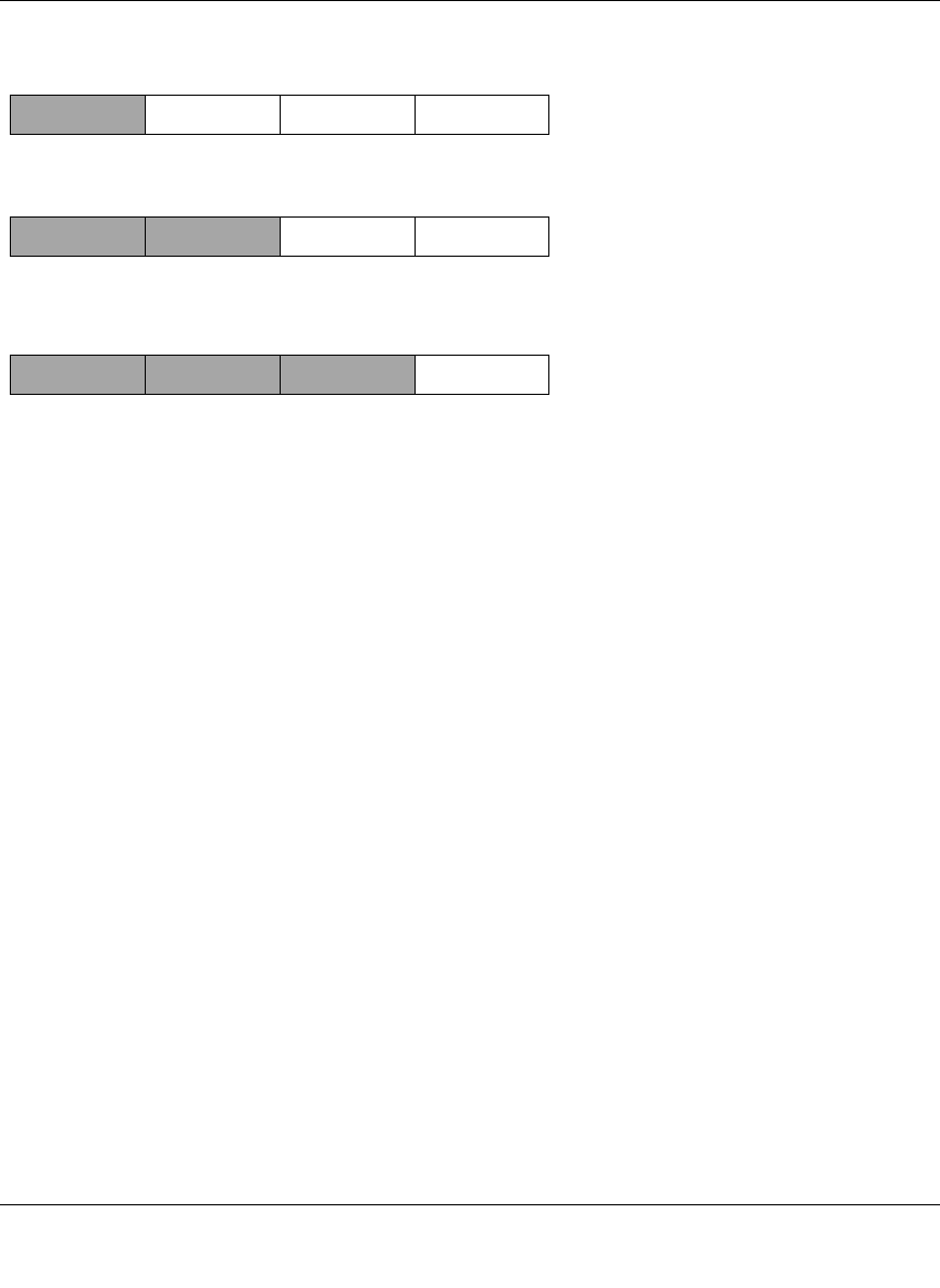
Reference Manual for the 54 Mbps Wireless Travel Router WGR101
Network, Routing, Firewall, and Basics B-3
May 2004 (202-10034-01)
Figure B-1: Three Main Address Classes
The five address classes are:
• Class A
Class A addresses can have up to 16,777,214 hosts on a single network. They use an eight-bit
network number and a 24-bit node number. Class A addresses are in this range:
1.x.x.x to 126.x.x.x.
• Class B
Class B addresses can have up to 65,354 hosts on a network. A Class B address uses a 16-bit
network number and a 16-bit node number. Class B addresses are in this range:
128.1.x.x to 191.254.x.x.
• Class C
Class C addresses can have 254 hosts on a network. Class C addresses use 24 bits for the
network address and eight bits for the node. They are in this range:
192.0.1.x to 223.255.254.x.
• Class D
Class D addresses are used for multicasts (messages sent to many hosts). Class D addresses are
in this range:
224.0.0.0 to 239.255.255.255.
• Class E
Class E addresses are for experimental use.
7261
C
lass A
N
etwork Node
C
lass B
C
lass C
Network Node
Network Node

Reference Manual for the 54 Mbps Wireless Travel Router WGR101
B-4 Network, Routing, Firewall, and Basics
May 2004 (202-10034-01)
This addressing structure allows IP addresses to uniquely identify each physical network and each
node on each physical network.
For each unique value of the network portion of the address, the base address of the range (host
address of all zeros) is known as the network address and is not usually assigned to a host. Also,
the top address of the range (host address of all ones) is not assigned, but is used as the broadcast
address for simultaneously sending a packet to all hosts with the same network address.
Netmask
In each of the address classes previously described, the size of the two parts (network address and
host address) is implied by the class. This partitioning scheme can also be expressed by a netmask
associated with the IP address. A netmask is a 32-bit quantity that, when logically combined (using
an AND operator) with an IP address, yields the network address. For instance, the netmasks for
Class A, B, and C addresses are 255.0.0.0, 255.255.0.0, and 255.255.255.0, respectively.
For example, the address 192.168.170.237 is a Class C IP address whose network portion is the
upper 24 bits. When combined (using an AND operator) with the Class C netmask, as shown here,
only the network portion of the address remains:
11000000 10101000 10101010 11101101 (192.168.170.237)
combined with:
11111111 11111111 11111111 00000000 (255.255.255.0)
Equals:
11000000 10101000 10101010 00000000 (192.168.170.0)
As a shorter alternative to dotted-decimal notation, the netmask may also be expressed in terms of
the number of ones from the left. This number is appended to the IP address, following a backward
slash (/), as “/n.” In the example, the address could be written as 192.168.170.237/24, indicating
that the netmask is 24 ones followed by 8 zeros.
Subnet Addressing
By looking at the addressing structures, you can see that even with a Class C address, there are a
large number of hosts per network. Such a structure is an inefficient use of addresses if each end of
a routed link requires a different network number. It is unlikely that the smaller office LANs would
have that many devices. You can resolve this problem by using a technique known as subnet
addressing.
Reference Manual for the 54 Mbps Wireless Travel Router WGR101
Network, Routing, Firewall, and Basics B-5
May 2004 (202-10034-01)
Subnet addressing allows us to split one IP network address into smaller multiple physical
networks known as subnetworks. Some of the node numbers are used as a subnet number instead.
A Class B address gives us 16 bits of node numbers translating to 64,000 nodes. Most
organizations do not use 64,000 nodes, so there are free bits that can be reassigned. Subnet
addressing makes use of those bits that are free, as shown below.
Figure B-2: Example of Subnetting a Class B Address
A Class B address can be effectively translated into multiple Class C addresses. For example, the
IP address of 172.16.0.0 is assigned, but node addresses are limited to 255 maximum, allowing
eight extra bits to use as a subnet address. The IP address of 172.16.97.235 would be interpreted as
IP network address 172.16, subnet number 97, and node number 235. In addition to extending
the number of addresses available, subnet addressing provides other benefits. Subnet addressing
allows a network manager to construct an address scheme for the network by using different
subnets for other geographical locations in the network or for other departments in the
organization.
Although the preceding example uses the entire third octet for a subnet address, note that you are
not restricted to octet boundaries in subnetting. To create more network numbers, you need only
shift some bits from the host address to the network address. For instance, to partition a Class C
network number (192.68.135.0) into two, you shift one bit from the host address to the network
address. The new netmask (or subnet mask) is 255.255.255.128. The first subnet has network
number 192.68.135.0 with hosts 192.68.135.1 to 129.68.135.126, and the second subnet has
network number 192.68.135.128 with hosts 192.68.135.129 to 192.68.135.254.
Note: The number 192.68.135.127 is not assigned because it is the broadcast address
of the first subnet. The number 192.68.135.128 is not assigned because it is the network
address of the second subnet.
7262
C
lass B
Network Subnet Node

Reference Manual for the 54 Mbps Wireless Travel Router WGR101
B-6 Network, Routing, Firewall, and Basics
May 2004 (202-10034-01)
The following table lists the additional subnet mask bits in dotted-decimal notation. To use the
table, write down the original class netmask and replace the 0 value octets with the dotted-decimal
value of the additional subnet bits. For example, to partition your Class C network with subnet
mask 255.255.255.0 into 16 subnets (4 bits), the new subnet mask becomes 255.255.255.240.
The following table displays several common netmask values in both the dotted-decimal and the
masklength formats.
Configure all hosts on a LAN segment to use the same netmask for the following reasons:
Table 7-1. Netmask Notation Translation Table for One Octet
Number of Bits Dotted-Decimal Value
1 128
2 192
3 224
4 240
5 248
6 252
7 254
8 255
Table 7-2. Netmask Formats
Dotted-Decimal Masklength
255.0.0.0 /8
255.255.0.0 /16
255.255.255.0 /24
255.255.255.128 /25
255.255.255.192 /26
255.255.255.224 /27
255.255.255.240 /28
255.255.255.248 /29
255.255.255.252 /30
255.255.255.254 /31
255.255.255.255 /32

Reference Manual for the 54 Mbps Wireless Travel Router WGR101
Network, Routing, Firewall, and Basics B-7
May 2004 (202-10034-01)
• So that hosts recognize local IP broadcast packets
When a device broadcasts to its segment neighbors, it uses a destination address of the local
network address with all ones for the host address. In order for this scheme to work, all devices
on the segment must agree on which bits comprise the host address.
• So that a local router or bridge recognizes which addresses are local and which are remote
Private IP Addresses
If your local network is isolated from the Internet (for example, when using NAT), you can assign
any IP addresses to the hosts without problems. However, the IANA has reserved the following
three blocks of IP addresses specifically for private networks:
10.0.0.0 - 10.255.255.255
172.16.0.0 - 172.31.255.255
192.168.0.0 - 192.168.255.255
Choose your private network number from this range. The DHCP server of the WGR101 wireless
travel router is preconfigured to automatically assign private addresses.
Regardless of your particular situation, do not create an arbitrary IP address; always follow the
guidelines explained here. For more information about address assignment, refer to RFC 1597,
Address Allocation for Private Internets, and RFC 1466, Guidelines for Management of IP
Address Space. The Internet Engineering Task Force (IETF) publishes RFCs on its web site at
www.ietf.org.
Single IP Address Operation Using NAT
In the past, if multiple computers on a LAN needed to access the Internet simultaneously, you had
to obtain a range of IP addresses from the ISP. This type of Internet account is more costly than a
single-address account typically used by a single user with a modem, rather than a router. The
WGR101 wireless travel router employs an address-sharing method called Network Address
Translation (NAT). This method allows several networked computers to share an Internet account
using only a single IP address, which may be statically or dynamically assigned by your ISP.
The router accomplishes this address sharing by translating the internal LAN IP addresses to a
single address that is globally unique on the Internet. The internal LAN IP addresses can be either
private addresses or registered addresses. For more information about IP address translation, refer
to RFC 1631, The IP Network Address Translator (NAT).
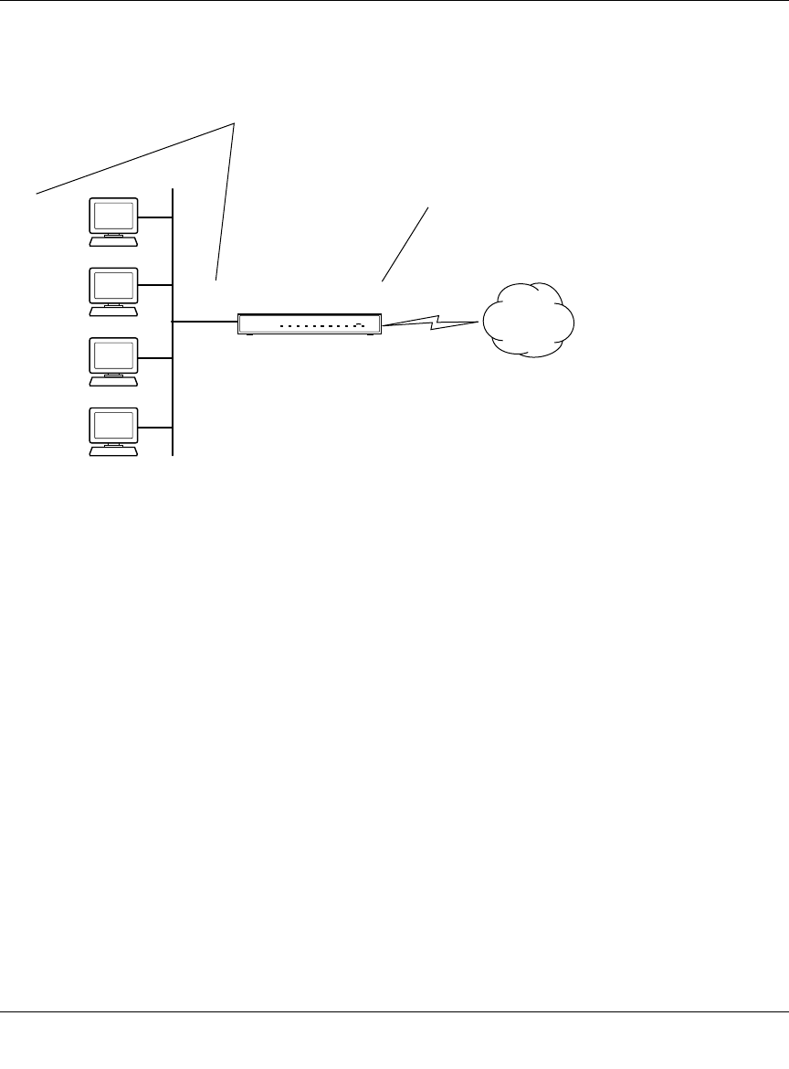
Reference Manual for the 54 Mbps Wireless Travel Router WGR101
B-8 Network, Routing, Firewall, and Basics
May 2004 (202-10034-01)
The following figure illustrates a single IP address operation.
Figure B-3: Single IP Address Operation Using NAT
This scheme offers the additional benefit of firewall-like protection because the internal LAN
addresses are not available to the Internet through the translated connection. All incoming
inquiries are filtered out by the router. This filtering can prevent intruders from probing your
system. However, using port forwarding, you can allow one computer (for example, a web server)
on your local network to be accessible to outside users.
MAC Addresses and Address Resolution Protocol
An IP address alone cannot be used to deliver data from one LAN device to another. To send data
between LAN devices, you must convert the IP address of the destination device to its media
access control (MAC) address. Each device on an Ethernet network has a unique MAC address,
which is a 48-bit number assigned to each device by the manufacturer. The technique that
associates the IP address with a MAC address is known as address resolution. Internet Protocol
uses the Address Resolution Protocol (ARP) to resolve MAC addresses.
7786EA
1
92.168.0.2
1
92.168.0.3
1
92.168.0.4
1
92.168.0.5
192.168.0.1 172.21.15.105
Private IP addresses
assigned by user
Internet
IP addresses
assigned by ISP

Reference Manual for the 54 Mbps Wireless Travel Router WGR101
Network, Routing, Firewall, and Basics B-9
May 2004 (202-10034-01)
If a device sends data to another station on the network and the destination MAC address is not yet
recorded, ARP is used. An ARP request is broadcast onto the network. All stations on the network
receive and read the request. The destination IP address for the chosen station is included as part of
the message so that only the station with this IP address responds to the ARP request. All other
stations discard the request.
Related Documents
The station with the correct IP address responds with its own MAC address directly to the sending
device. The receiving station provides the transmitting station with the required destination MAC
address. The IP address data and MAC address data for each station are held in an ARP table. The
next time data is sent, the address can be obtained from the address information in the table.
For more information about address assignment, refer to the IETF documents RFC 1597, Address
Allocation for Private Internets, and RFC 1466, Guidelines for Management of IP Address Space.
For more information about IP address translation, refer to RFC 1631, The IP Network Address
Translator (NAT).
Domain Name Server
Many of the resources on the Internet can be addressed by simple descriptive names such as
www.NETGEAR.com. This addressing is very helpful at the application level, but the descriptive
name must be translated to an IP address in order for a user to actually contact the resource. Just as
a telephone directory maps names to phone numbers, or as an ARP table maps IP addresses to
MAC addresses, a domain name system (DNS) server maps descriptive names of network
resources to IP addresses.
When a computer accesses a resource by its descriptive name, it first contacts a DNS server to
obtain the IP address of the resource. The computer sends the desired message using the IP
address. Many large organizations, such as ISPs, maintain their own DNS servers and allow their
customers to use the servers to look up addresses.

Reference Manual for the 54 Mbps Wireless Travel Router WGR101
B-10 Network, Routing, Firewall, and Basics
May 2004 (202-10034-01)
IP Configuration by DHCP
When an IP-based local area network is installed, each computer must be configured with an
IP address. If the computers need to access the Internet, they should also be configured with a
gateway address and one or more DNS server addresses. As an alternative to manual
configuration, there is a method by which each computer on the network can automatically obtain
this configuration information. A device on the network may act as a Dynamic Host Configuration
Protocol (DHCP) server. The DHCP server stores a list or pool of IP addresses, along with other
information (such as gateway and DNS addresses) that it may assign to the other devices on the
network. The WGR101 wireless travel router has the capacity to act as a DHCP server.
The WGR101 wireless travel router also functions as a DHCP client when connecting to the ISP.
The router can automatically obtain an IP address, subnet mask, DNS server addresses, and a
gateway address if the ISP provides this information by DHCP.
Internet Security and Firewalls
When your LAN connects to the Internet through a router, an opportunity is created for outsiders
to access or disrupt your network. A NAT router provides some protection because by the very
nature of the process, the network behind the router is shielded from access by outsiders on the
Internet. However, there are methods by which a determined hacker can possibly obtain
information about your network or at the least can disrupt your Internet access. A greater degree of
protection is provided by a firewall router.
What is a Firewall?
A firewall is a device that protects one network from another, while allowing communication
between the two. A firewall incorporates the functions of the NAT router, while adding features for
dealing with a hacker intrusion or attack. Several known types of intrusion or attack can be
recognized when they occur. When an incident is detected, the firewall can log details of the
attempt, and can optionally send email to an administrator notifying them of the incident. Using
information from the log, the administrator can take action with the ISP of the hacker. In some
types of intrusions, the firewall can fend off the hacker by discarding all further packets from the
hacker’s IP address for a period of time.

Reference Manual for the 54 Mbps Wireless Travel Router WGR101
Network, Routing, Firewall, and Basics B-11
May 2004 (202-10034-01)
Stateful Packet Inspection
Unlike simple Internet sharing routers, a firewall uses a process called stateful packet inspection to
ensure secure firewall filtering to protect your network from attacks and intrusions. Since
user-level applications such as FTP and web browsers can create complex patterns of network
traffic, it is necessary for the firewall to analyze groups of network connection states. Using
Stateful Packet Inspection, an incoming packet is intercepted at the network layer and then
analyzed for state-related information associated with all network connections. A central cache
within the firewall keeps track of the state information associated with all network connections.
All traffic passing through the firewall is analyzed against the state of these connections in order to
determine whether or not it will be allowed to pass through or rejected.
Denial of Service Attack
A hacker may be able to prevent your network from operating or communicating by launching a
Denial of Service (DoS) attack. The method used for such an attack can be as simple as merely
flooding your site with more requests than it can handle. A more sophisticated attack may attempt
to exploit some weakness in the operating system used by your router or gateway. Some operating
systems can be disrupted by simply sending a packet with incorrect length information.
Ethernet Cabling
Although Ethernet networks originally used thick or thin coaxial cable, most installations currently
use unshielded twisted pair (UTP) cabling. The UTP cable contains eight conductors, arranged in
four twisted pairs, and terminated with an RJ45 type connector. A normal straight-through UTP
Ethernet cable follows the EIA568B standard wiring as described below in Table B-1.

Reference Manual for the 54 Mbps Wireless Travel Router WGR101
B-12 Network, Routing, Firewall, and Basics
May 2004 (202-10034-01)
Category 5 Cable Quality
Category 5 distributed cable that meets ANSI/EIA/TIA-568-A building wiring standards can be a
maximum of 328 feet (ft.) or 100 meters (m) in length, divided as follows:
20 ft. (6 m) between the hub and the patch panel (if used)
295 ft. (90 m) from the wiring closet to the wall outlet
10 ft. (3 m) from the wall outlet to the desktop device
The patch panel and other connecting hardware must meet the requirements for 100 Mbps
operation (Category 5). Only 0.5 inch (1.5 cm) of untwist in the wire pair is allowed at any
termination point.
A twisted pair Ethernet network operating at 10 Mbits/second (10BASE-T) will often tolerate low
quality cables, but at 100 Mbits/second (10BASE-Tx) the cable must be rated as Category 5, or
Cat 5, by the Electronic Industry Association (EIA). This rating will be printed on the cable jacket.
A Category 5 cable will meet specified requirements regarding loss and crosstalk. In addition,
there are restrictions on maximum cable length for both 10 and 100 Mbits/second networks.
Table B-1. UTP Ethernet cable wiring, straight-through
Pin Wire color Signal
1 Orange/White Transmit (Tx) +
2 Orange Transmit (Tx) -
3 Green/White Receive (Rx) +
4Blue
5 Blue/White
6 Green Receive (Rx) -
7 Brown/White
8Brown
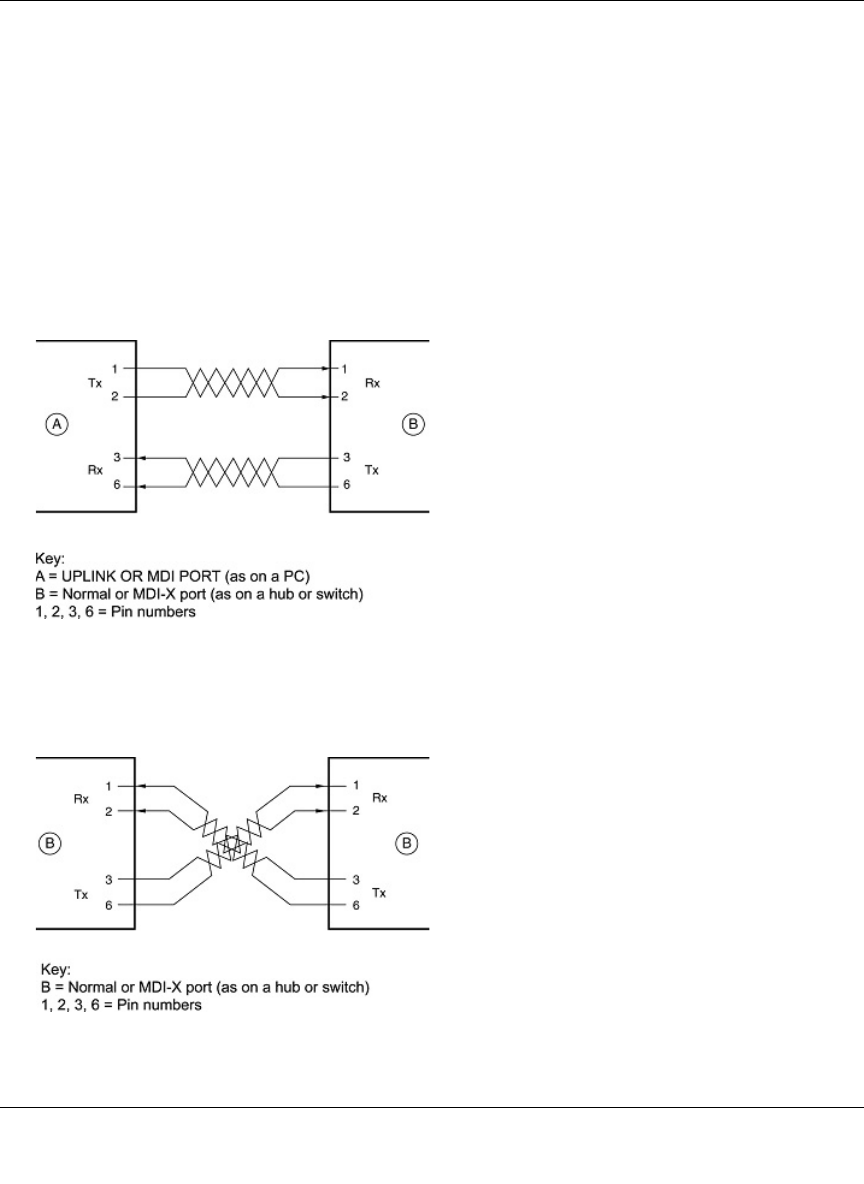
Reference Manual for the 54 Mbps Wireless Travel Router WGR101
Network, Routing, Firewall, and Basics B-13
May 2004 (202-10034-01)
Inside Twisted Pair Cables
For two devices to communicate, the transmitter of each device must be connected to the receiver
of the other device. The crossover function is usually implemented internally as part of the
circuitry in the device. Computers and workstation adapter cards are usually media-dependent
interface ports, called MDI or uplink ports. Most repeaters and switch ports are configured as
media-dependent interfaces with built-in crossover ports, called MDI-X or normal ports. Auto
Uplink technology automatically senses which connection, MDI or MDI-X, is needed and makes
the right connection.
Figure B-4 illustrates straight-through twisted pair cable.
Figure B-4: Straight-Through Twisted-Pair Cable
Figure B-5 illustrates crossover twisted pair cable.
Figure B-5: Crossover Twisted-Pair Cable
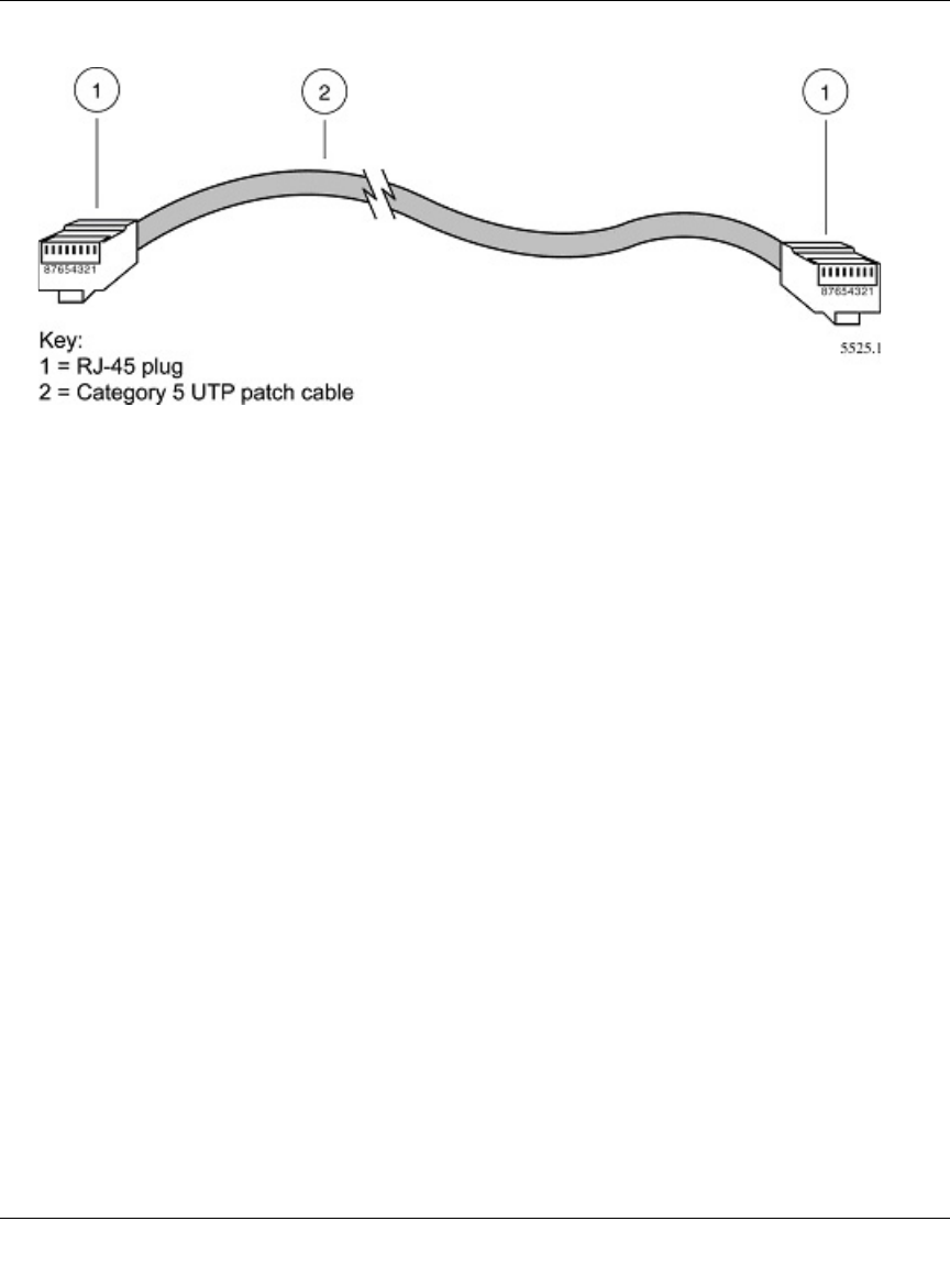
Reference Manual for the 54 Mbps Wireless Travel Router WGR101
B-14 Network, Routing, Firewall, and Basics
May 2004 (202-10034-01)
Figure B-6: Category 5 UTP Cable with Male RJ-45 Plug at Each End
Note: Flat “silver satin” telephone cable may have the same RJ-45 plug. However, using telephone
cable results in excessive collisions, causing the attached port to be partitioned or disconnected
from the network.
Uplink Switches, Crossover Cables, and MDI/MDIX Switching
In the wiring table above, the concept of transmit and receive are from the perspective of the
computer, which is wired as Media Dependant Interface (MDI). In this wiring, the computer
transmits on pins 1 and 2. At the hub, the perspective is reversed, and the hub receives on pins 1
and 2. This wiring is referred to as Media Dependant Interface - Crossover (MDI-X).
When connecting a computer to a computer, or a hub port to another hub port, the transmit pair
must be exchanged with the receive pair. This exchange is done by one of two mechanisms. Most
hubs provide an Uplink switch which will exchange the pairs on one port, allowing that port to be
connected to another hub using a normal Ethernet cable. The second method is to use a crossover
cable, which is a special cable in which the transmit and receive pairs are exchanged at one of the
two cable connectors. Crossover cables are often unmarked as such, and must be identified by
comparing the two connectors. Since the cable connectors are clear plastic, it is easy to place them
side by side and view the order of the wire colors on each. On a straight-through cable, the color
order will be the same on both connectors. On a crossover cable, the orange and blue pairs will be
exchanged from one connector to the other.

Reference Manual for the 54 Mbps Wireless Travel Router WGR101
Network, Routing, Firewall, and Basics B-15
May 2004 (202-10034-01)
The WGR101 wireless travel router incorporates Auto UplinkTM technology (also called MDI/
MDIX). Each LOCAL Ethernet port will automatically sense whether the Ethernet cable plugged
into the port should have a normal connection (e.g. connecting to a computer) or an uplink
connection (e.g. connecting to a router, switch, or hub). That port will then configure itself to the
correct configuration. This feature also eliminates the need to worry about crossover cables, as
Auto UplinkTM will accommodate either type of cable to make the right connection.

Reference Manual for the 54 Mbps Wireless Travel Router WGR101
B-16 Network, Routing, Firewall, and Basics
May 2004 (202-10034-01)
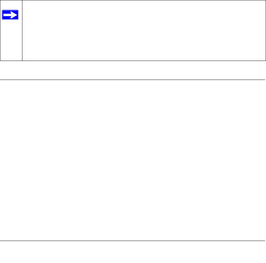
Preparing Your Network C-1
May 2004 (202-10034-01)
Appendix C
Preparing Your Network
This appendix describes how to prepare your network to connect to the Internet through the 54
Mbps Wireless Travel Router WGR101 and how to verify the readiness of broadband Internet
service from an Internet service provider (ISP).
Preparing Your Computers for TCP/IP Networking
Computers access the Internet using a protocol called TCP/IP (Transmission Control Protocol/
Internet Protocol). Each computer on your network must have TCP/IP installed and selected as its
networking protocol. If a Network Interface Card (NIC) is already installed in your computer, then
TCP/IP is probably already installed as well.
Most operating systems include the software components you need for networking with TCP/IP:
•Windows
® 95 or later includes the software components for establishing a TCP/IP network.
• Windows 3.1 does not include a TCP/IP component. You need to purchase a third-party TCP/
IP application package such as NetManage Chameleon.
• Macintosh Operating System 7 or later includes the software components for establishing a
TCP/IP network.
• All versions of UNIX or Linux include TCP/IP components. Follow the instructions provided
with your operating system or networking software to install TCP/IP on your computer.
Note: If an ISP technician configured your computer during the installation of a
broadband modem, or if you configured it using instructions provided by your ISP, you
may need to copy the current configuration information for use in the configuration of
your router. Write down this information before reconfiguring your computers. Refer to
“Obtaining ISP Configuration Information for Windows Computers” on page C-19 or
“Obtaining ISP Configuration Information for Macintosh Computers” on page C-20 for
further information.

Reference Manual for the 54 Mbps Wireless Travel Router WGR101
C-2 Preparing Your Network
May 2004 (202-10034-01)
In your IP network, each computer and the router must be assigned a unique IP addresses. Each
computer must also have certain other IP configuration information such as a subnet mask
(netmask), a domain name server (DNS) address, and a default gateway address. In most cases,
you should install TCP/IP so that the computer obtains its specific network configuration
information automatically from a DHCP server during bootup. For a detailed explanation of the
meaning and purpose of these configuration items, refer to “Appendix B, “Network, Routing,
Firewall, and Basics.”
The WGR101 wireless travel router is shipped preconfigured as a DHCP server. The router assigns
the following TCP/IP configuration information automatically when the computers are rebooted:
• computer or workstation IP addresses—192.168.0.2 through 192.168.0.254
• Subnet mask—255.255.255.0
• Gateway address (the router)—192.168.0.1
These addresses are part of the IETF-designated private address range for use in private networks.
Configuring Windows 95, 98, and Me for TCP/IP Networking
As part of the PC preparation process, you need to manually install and configure TCP/IP on each
networked PC. Before starting, locate your Windows CD; you may need to insert it during the
TCP/IP installation process.
Install or Verify Windows Networking Components
To install or verify the necessary components for IP networking:
1. On the Windows taskbar, click the Start button, point to Settings, and then click Control Panel.
2. Double-click the Network icon.
The Network window opens, which displays a list of installed components:
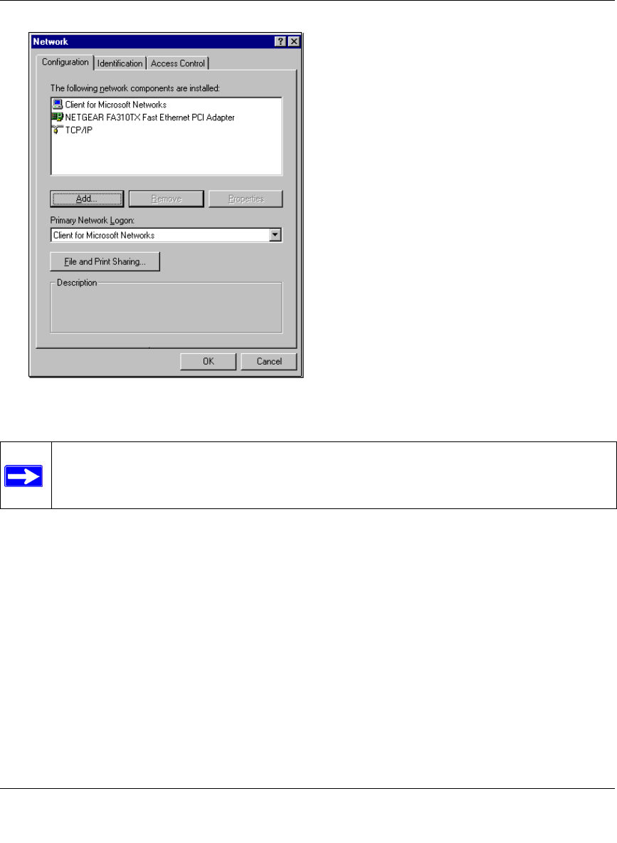
Reference Manual for the 54 Mbps Wireless Travel Router WGR101
Preparing Your Network C-3
May 2004 (202-10034-01)
You must have an Ethernet adapter, the TCP/IP protocol, and Client for Microsoft Networks.
If you need to install a new adapter, follow these steps:
a. Click the Add button.
b. Select Adapter, and then click Add.
c. Select the manufacturer and model of your Ethernet adapter, and then click OK.
If you need TCP/IP:
a. Click the Add button.
b. Select Protocol, and then click Add.
c. Select Microsoft.
d. Select TCP/IP, and then click OK.
Note: It is not necessary to remove any other network components shown in the
Network window in order to install the adapter, TCP/IP, or Client for Microsoft
Networks.

Reference Manual for the 54 Mbps Wireless Travel Router WGR101
C-4 Preparing Your Network
May 2004 (202-10034-01)
If you need Client for Microsoft Networks:
a. Click the Add button.
b. Select Client, and then click Add.
c. Select Microsoft.
d. Select Client for Microsoft Networks, and then click OK.
3. Restart your PC for the changes to take effect.
Enabling DHCP to Automatically Configure TCP/IP Settings
After the TCP/IP protocol components are installed, each PC must be assigned specific
information about itself and resources that are available on its network. The simplest way to
configure this information is to allow the PC to obtain the information from a DHCP server in the
network.
You will find there are many similarities in the procedures for different Windows systems
when using DHCP to configure TCP/IP.
The following steps will walk you through the configuration process for each of these
versions of Windows.
Locate your Network Neighborhood icon.
• If the Network Neighborhood icon is on the Windows desktop, position your mouse
pointer over it and right-click your mouse button.
• If the icon is not on the desktop,
• Click Start on the task bar located at the bottom left of the window.
• Choose Settings, and then Control Panel.
• Locate the Network Neighborhood icon and click on it. This will open the Network
panel as shown below.
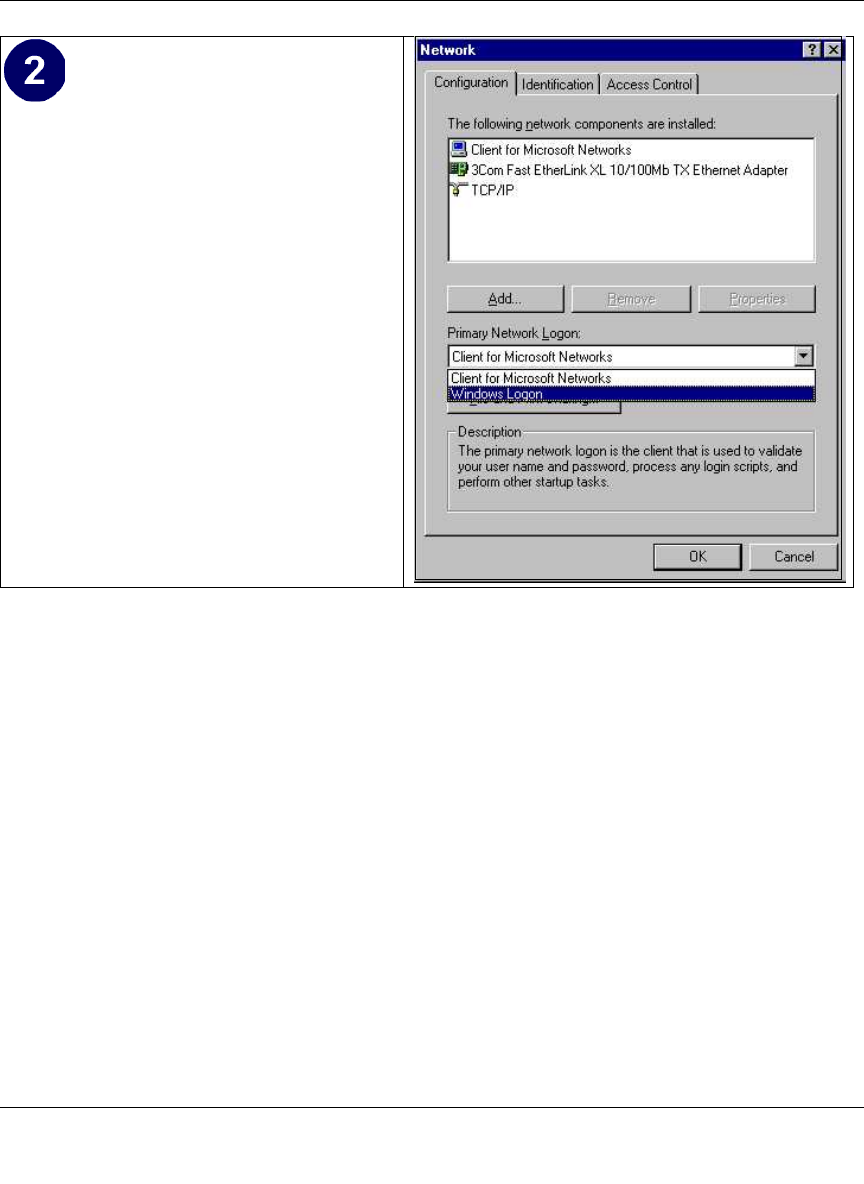
Reference Manual for the 54 Mbps Wireless Travel Router WGR101
Preparing Your Network C-5
May 2004 (202-10034-01)
Verify the following settings as shown:
• Client for Microsoft Network exists
• Ethernet adapter is present
• TCP/IP is present
•Primary Network Logon is set to
Windows logon
Click on the Properties button. The
following TCP/IP Properties window will
display.
Reference Manual for the 54 Mbps Wireless Travel Router WGR101
C-6 Preparing Your Network
May 2004 (202-10034-01)
Selecting Windows’ Internet Access Method
1. On the Windows taskbar, click the Start button, point to Settings, and then click Control Panel.
2. Double-click the Internet Options icon.
3. Select “I want to set up my Internet connection manually” or “I want to connect through a
Local Area Network” and click Next.
4. Select “I want to connect through a Local Area Network” and click Next.
5. Uncheck all boxes in the LAN Internet Configuration screen and click Next.
6. Proceed to the end of the Wizard.
Verifying TCP/IP Properties
After your PC is configured and has rebooted, you can check the TCP/IP configuration using the
utility winipcfg.exe:
1. On the Windows taskbar, click the Start button, and then click Run.
• By default, the IP Address tab is open on
this window.
• Verify the following:
Obtain an IP address automatically is
selected. If not selected, click in the radio
button to the left of it to select it. This
setting is required to enable the DHCP server
to automatically assign an IP address.
• Click OK to continue.
Restart the PC.
Repeat these steps for each PC with this
version of Windows on your network.

Reference Manual for the 54 Mbps Wireless Travel Router WGR101
Preparing Your Network C-7
May 2004 (202-10034-01)
2. Type winipcfg, and then click OK.
The IP Configuration window opens, which lists (among other things), your IP address, subnet
mask, and default gateway.
3. From the drop-down box, select your Ethernet adapter.
The window is updated to show your settings, which should match the values below if you are
using the default TCP/IP settings that NETGEAR recommends for connecting through a
router or gateway:
• The IP address is between 192.168.0.2 and 192.168.0.254
• The subnet mask is 255.255.255.0
• The default gateway is 192.168.0.1
Configuring Windows NT4, 2000 or XP for IP Networking
As part of the PC preparation process, you may need to install and configure
TCP/IP on each networked PC. Before starting, locate your Windows CD; you may need to insert
it during the TCP/IP installation process.
Install or Verify Windows Networking Components
To install or verify the necessary components for IP networking:
1. On the Windows taskbar, click the Start button, point to Settings, and then click Control Panel.
2. Double-click the Network and Dialup Connections icon.
3. If an Ethernet adapter is present in your PC, you should see an entry for Local Area
Connection. Double-click that entry.
4. Select Properties.
5. Verify that ‘Client for Microsoft Networks’ and ‘Internet Protocol (TCP/IP)’ are present. If
not, select Install and add them.
6. Select ‘Internet Protocol (TCP/IP)’, click Properties, and verify that “Obtain an IP address
automatically is selected.
7. Click OK and close all Network and Dialup Connections windows.
8. Then, restart your PC.
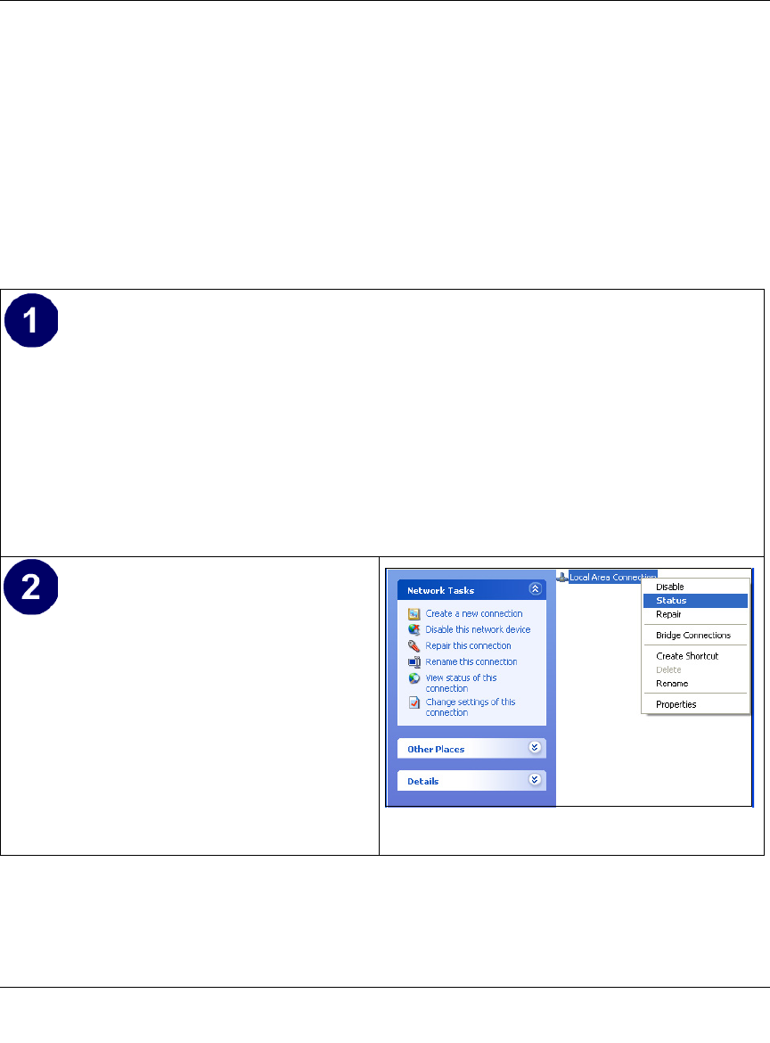
Reference Manual for the 54 Mbps Wireless Travel Router WGR101
C-8 Preparing Your Network
May 2004 (202-10034-01)
DHCP Configuration of TCP/IP in Windows XP, 2000, or NT4
You will find there are many similarities in the procedures for different Windows systems when
using DHCP to configure TCP/IP.
The following steps will walk you through the configuration process for each of these versions of
Windows.
DHCP Configuration of TCP/IP in Windows XP
Locate your Network Neighborhood icon.
• Select Control Panel from the Windows XP new Start Menu.
• Select the Network Connections icon on the Control Panel. This will take you to the next
step.
• Now the Network Connection window
displays.
The Connections List that shows all the
network connections set up on the PC,
located to the right of the window.
• Right-click on the Connection you will
use and choose Status.
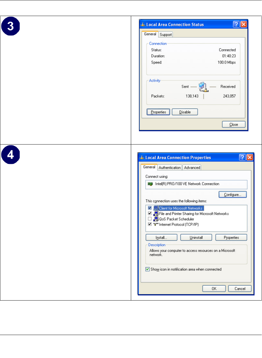
Reference Manual for the 54 Mbps Wireless Travel Router WGR101
Preparing Your Network C-9
May 2004 (202-10034-01)
• Now you should be at the Local Area
Network Connection Status window. This
box displays the connection status, duration,
speed, and activity statistics.
• Administrator logon access rights are needed
to use this window.
• Click the Properties button to view details
about the connection.
• The TCP/IP details are presented on the
Support tab page.
• Select Internet Protocol, and click
Properties to view the configuration
information.
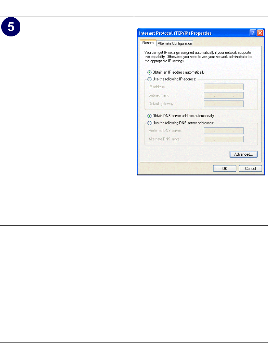
Reference Manual for the 54 Mbps Wireless Travel Router WGR101
C-10 Preparing Your Network
May 2004 (202-10034-01)
DHCP Configuration of TCP/IP in Windows 2000
Once again, after you have installed the network card, TCP/IP for Windows 2000 is configured.
TCP/IP should be added by default and set to DHCP without your having to configure it.
However, if there are problems, follow these steps to configure TCP/IP with DHCP for Windows
2000.
• Verify that the Obtain an IP address
automatically radio button is selected.
• Verify that Obtain DNS server address
automatically radio button is selected.
• Click the OK button.
This completes the DHCP configuration of TCP/
IP in Windows XP.
Repeat these steps for each PC with this version
of Windows on your network.
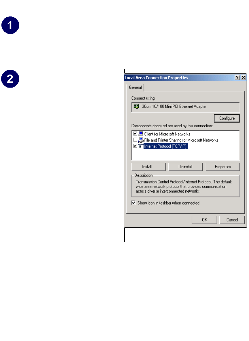
Reference Manual for the 54 Mbps Wireless Travel Router WGR101
Preparing Your Network C-11
May 2004 (202-10034-01)
• Click on the My Network Places icon on the Windows desktop. This will bring up a window
called Network and Dial-up Connections.
• Right click on Local Area Connection and select Properties.
•The Local Area Connection Properties
dialog box appears.
• Verify that you have the correct Ethernet
card selected in the Connect using: box.
• Verify that at least the following two items
are displayed and selected in the box of
“Components checked are used by this
connection:”
• Client for Microsoft Networks and
• Internet Protocol (TCP/IP)
• Click OK.
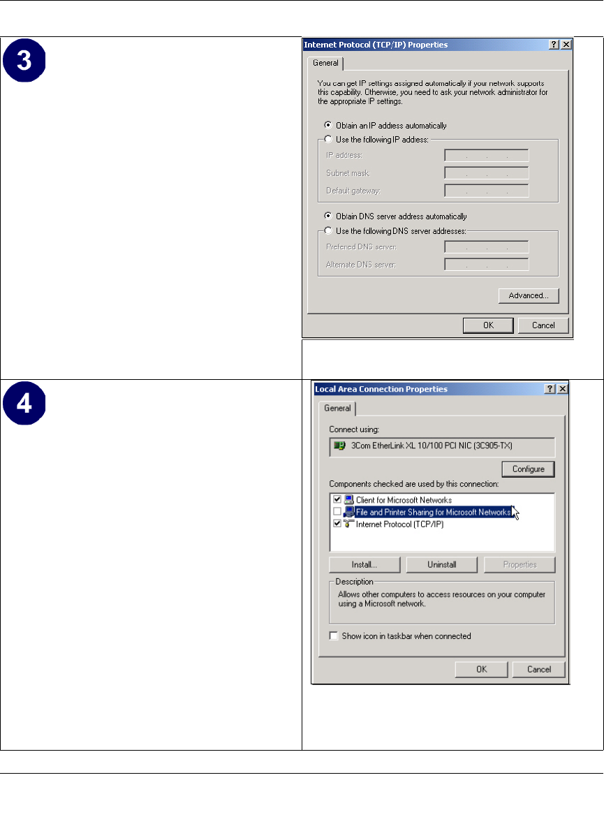
Reference Manual for the 54 Mbps Wireless Travel Router WGR101
C-12 Preparing Your Network
May 2004 (202-10034-01)
• With Internet Protocol (TCP/IP) selected,
click on Properties to open the Internet
Protocol (TCP/IP) Properties dialogue box.
• Verify that
•Obtain an IP address automatically is
selected.
•Obtain DNS server address
automatically is selected.
• Click OK to return to Local Area
Connection Properties.
• Click OK again to complete the
configuration process for Windows 2000.
Restart the PC.
Repeat these steps for each PC with this version
of Windows on your network.
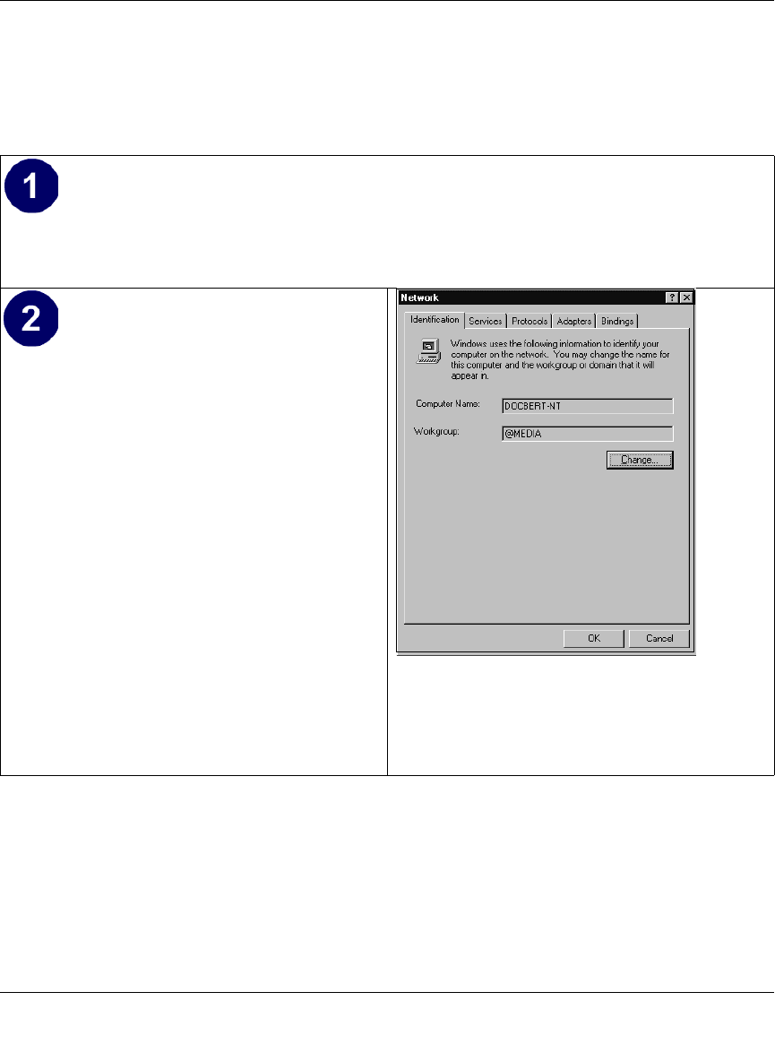
Reference Manual for the 54 Mbps Wireless Travel Router WGR101
Preparing Your Network C-13
May 2004 (202-10034-01)
DHCP Configuration of TCP/IP in Windows NT4
Once you have installed the network card, you need to configure the TCP/IP environment for
Windows NT 4.0. Follow this procedure to configure TCP/IP with DHCP in Windows NT 4.0.
• Choose Settings from the Start Menu, and then select Control Panel.
This will display Control Panel window.
• Double-click the Network icon in the
Control Panel window.
The Network panel will display.
• Select the Protocols tab to continue.
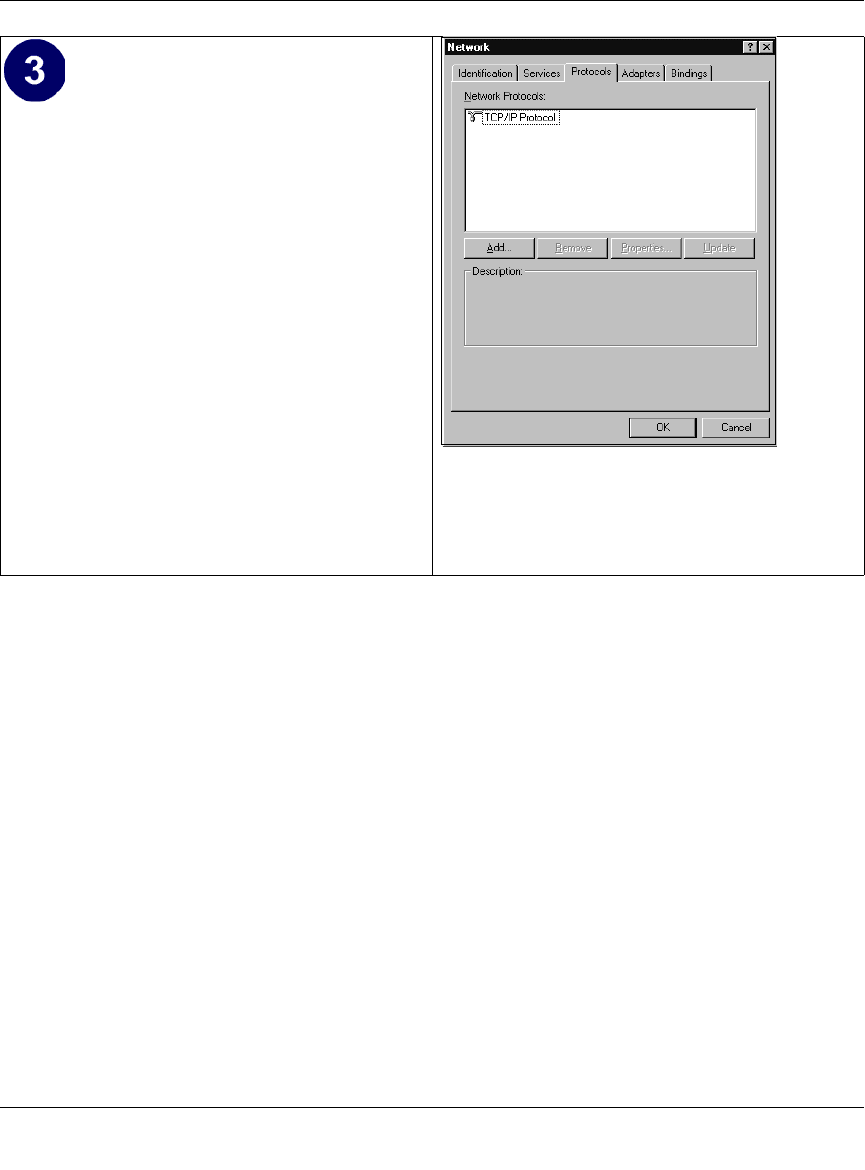
Reference Manual for the 54 Mbps Wireless Travel Router WGR101
C-14 Preparing Your Network
May 2004 (202-10034-01)
• Highlight the TCP/IP Protocol in the
Network Protocols box, and click on the
Properties button.
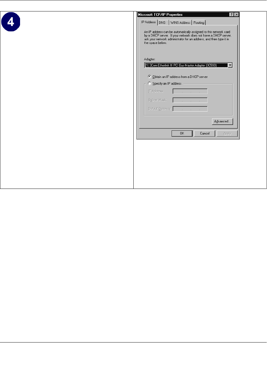
Reference Manual for the 54 Mbps Wireless Travel Router WGR101
Preparing Your Network C-15
May 2004 (202-10034-01)
Verifying TCP/IP Properties for Windows XP, 2000, and NT4
To check your PC’s TCP/IP configuration:
1. On the Windows taskbar, click the Start button, and then click Run.
The Run window opens.
2. Type cmd and then click OK.
A command window opens
3. Type ipconfig /all
Your IP Configuration information will be listed, and should match the values below if you are
using the default TCP/IP settings that NETGEAR recommends for connecting through a
router or gateway:
• The IP address is between 192.168.0.2 and 192.168.0.254
• The subnet mask is 255.255.255.0
•The TCP/IP Properties dialog box now
displays.
• Click the IP Address tab.
• Select the radio button marked Obtain an IP
address from a DHCP server.
• Click OK. This completes the configuration
of TCP/IP in Windows NT.
Restart the PC.
Repeat these steps for each PC with this version
of Windows on your network.
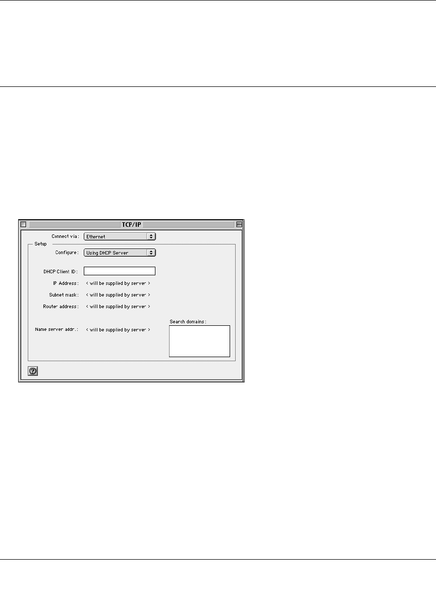
Reference Manual for the 54 Mbps Wireless Travel Router WGR101
C-16 Preparing Your Network
May 2004 (202-10034-01)
• The default gateway is 192.168.0.1
4. Type exit
Configuring the Macintosh for TCP/IP Networking
Beginning with Macintosh Operating System 7, TCP/IP is already installed on the Macintosh. On
each networked Macintosh, you will need to configure TCP/IP to use DHCP.
MacOS 8.6 or 9.x
1. From the Apple menu, select Control Panels, then TCP/IP.
The TCP/IP Control Panel opens:
2. From the “Connect via” box, select your Macintosh’s Ethernet interface.
3. From the “Configure” box, select Using DHCP Server.
You can leave the DHCP Client ID box empty.
4. Close the TCP/IP Control Panel.
5. Repeat this for each Macintosh on your network.
MacOS X
1. From the Apple menu, choose System Preferences, then Network.
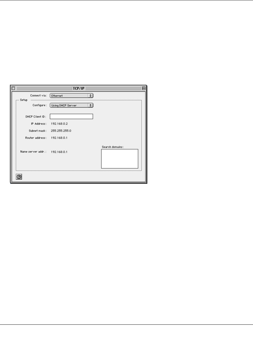
Reference Manual for the 54 Mbps Wireless Travel Router WGR101
Preparing Your Network C-17
May 2004 (202-10034-01)
2. If not already selected, select Built-in Ethernet in the Configure list.
3. If not already selected, Select Using DHCP in the TCP/IP tab.
4. Click Save.
Verifying TCP/IP Properties for Macintosh Computers
After your Macintosh is configured and has rebooted, you can check the TCP/IP configuration by
returning to the TCP/IP Control Panel. From the Apple menu, select Control Panels, then TCP/IP.
The panel is updated to show your settings, which should match the values below if you are using
the default TCP/IP settings that NETGEAR recommends:
• The IP Address is between 192.168.0.2 and 192.168.0.254
• The Subnet mask is 255.255.255.0
• The Router address is 192.168.0.1
If you do not see these values, you may need to restart your Macintosh or you may need to switch
the “Configure” setting to a different option, then back again to “Using DHCP Server”.

Reference Manual for the 54 Mbps Wireless Travel Router WGR101
C-18 Preparing Your Network
May 2004 (202-10034-01)
Verifying the Readiness of Your Internet Account
For broadband access to the Internet, you need to contract with an Internet service provider (ISP)
for a single-user Internet access account using a cable modem or DSL modem. This modem must
be a separate physical box (not a card) and must provide an Ethernet port intended for connection
to a Network Interface Card (NIC) in a computer. Your router does not support a USB-connected
broadband modem.
For a single-user Internet account, your ISP supplies TCP/IP configuration information for one
computer. With a typical account, much of the configuration information is dynamically assigned
when your computer is first booted up while connected to the ISP, and you will not need to know
that dynamic information.
In order to share the Internet connection among several computers, your router takes the place of
the single computer, and you need to configure it with the TCP/IP information that the single
computer would normally use. When the router’s Internet port is connected to the broadband
modem, the router appears to be a single computer to the ISP. The router then allows the computers
on the local network to masquerade as the single computer to access the Internet through the
broadband modem. The method used by the router to accomplish this is called Network Address
Translation (NAT) or IP masquerading.
Are Login Protocols Used?
Some ISPs require a special login protocol, in which you must enter a login name and password in
order to access the Internet. If you normally log in to your Internet account by running a program
such as WinPOET or EnterNet, then your account uses PPP over Ethernet (PPPoE).
When you configure your router, you will need to enter your login name and password in the
router’s configuration menus. After your network and router are configured, the router will
perform the login task when needed, and you will no longer need to run the login program from
your computer. It is not necessary to uninstall the login program.
What Is Your Configuration Information?
More and more, ISPs are dynamically assigning configuration information. However, if your ISP
does not dynamically assign configuration information but instead used fixed configurations, your
ISP should have given you the following basic information for your account:

Reference Manual for the 54 Mbps Wireless Travel Router WGR101
Preparing Your Network C-19
May 2004 (202-10034-01)
• An IP address and subnet mask
• A gateway IP address, which is the address of the ISP’s router
• One or more domain name server (DNS) IP addresses
• Host name and domain suffix
For example, your account’s full server names may look like this:
mail.xxx.yyy.com
In this example, the domain suffix is xxx.yyy.com.
If any of these items are dynamically supplied by the ISP, your router automatically acquires them.
If an ISP technician configured your computer during the installation of the broadband modem, or
if you configured it using instructions provided by your ISP, you need to copy the configuration
information from your computer’s Network TCP/IP Properties window or Macintosh TCP/IP
Control Panel before reconfiguring your computer for use with the router. These procedures are
described next.
Obtaining ISP Configuration Information for Windows Computers
As mentioned above, you may need to collect configuration information from your PC so that you
can use this information when you configure the WGR101 wireless travel router. Following this
procedure is only necessary when your ISP does not dynamically supply the account information.
To get the information you need to configure the router for Internet access:
1. On the Windows taskbar, click the Start button, point to Settings, and then click Control Panel.
2. Double-click the Network icon.
The Network window opens, which displays a list of installed components.
3. Select TCP/IP, and then click Properties.
The TCP/IP Properties dialog box opens.
4. Select the IP Address tab.
If an IP address and subnet mask are shown, write down the information. If an address is
present, your account uses a fixed (static) IP address. If no address is present, your account
uses a dynamically-assigned IP address. Click “Obtain an IP address automatically”.
5. Select the Gateway tab.

Reference Manual for the 54 Mbps Wireless Travel Router WGR101
C-20 Preparing Your Network
May 2004 (202-10034-01)
If an IP address appears under Installed Gateways, write down the address. This is the ISP’s
gateway address. Select the address and then click Remove to remove the gateway address.
6. Select the DNS Configuration tab.
If any DNS server addresses are shown, write down the addresses. If any information appears
in the Host or Domain information box, write it down. Click Disable DNS.
7. Click OK to save your changes and close the TCP/IP Properties dialog box.
You are returned to the Network window.
8. Click OK.
9. Reboot your PC at the prompt. You may also be prompted to insert your Windows CD.
Obtaining ISP Configuration Information for Macintosh
Computers
As mentioned above, you may need to collect configuration information from your Macintosh so
that you can use this information when you configure the WGR101 wireless travel router.
Following this procedure is only necessary when your ISP does not dynamically supply the
account information.
To get the information you need to configure the router for Internet access:
1. From the Apple menu, select Control Panels, then TCP/IP.
The TCP/IP Control Panel opens, which displays a list of configuration settings. If the
“Configure” setting is “Using DHCP Server”, your account uses a dynamically-assigned IP
address. In this case, close the Control Panel and skip the rest of this section.
2. If an IP address and subnet mask are shown, write down the information.
3. If an IP address appears under Router address, write down the address. This is the ISP’s
gateway address.
4. If any Name Server addresses are shown, write down the addresses. These are your ISP’s DNS
addresses.
5. If any information appears in the Search domains information box, write it down.
6. Change the “Configure” setting to “Using DHCP Server”.
7. Close the TCP/IP Control Panel.

Reference Manual for the 54 Mbps Wireless Travel Router WGR101
Preparing Your Network C-21
May 2004 (202-10034-01)
Restarting the Network
Once you’ve set up your computers to work with the router, you must reset the network for the
devices to be able to communicate correctly. Restart any computer that is connected to the firewall.
After configuring all of your computers for TCP/IP networking and restarting them, and
connecting them to the local network of your WGR101 wireless travel router, you are ready to
access and configure the router.

Reference Manual for the 54 Mbps Wireless Travel Router WGR101
C-22 Preparing Your Network
May 2004 (202-10034-01)
This page intentionally left blank.

Wireless Networking Basics D-1
May 2004 (202-10034-01)
Appendix D
Wireless Networking Basics
Wireless Networking Overview
The WGR101 wireless travel router conforms to the Institute of Electrical and Electronics
Engineers (IEEE) 802.11g standard for wireless LANs (WLANs). On an 802.11 wireless link, data
is encoded using direct-sequence spread-spectrum (DSSS) technology and is transmitted in the
unlicensed radio spectrum at 2.5GHz. The maximum data rate for the 802.11g wireless link is 54
Mbps, but it will automatically back down from 54 Mbps when the radio signal is weak or when
interference is detected.
The 802.11 standard is also called Wireless Ethernet or Wi-Fi by the Wireless Ethernet
Compatibility Alliance (WECA, see http://www.wi-fi.net), an industry standard group promoting
interoperability among 802.11 devices. The 802.11 standard offers two methods for configuring a
wireless network - ad hoc and infrastructure.
Infrastructure Mode
With a wireless access point, you can operate the wireless LAN in the infrastructure mode. This
mode provides wireless connectivity to multiple wireless network devices within a fixed range or
area of coverage, interacting with wireless nodes via an antenna.
In the infrastructure mode, the wireless access point converts airwave data into wired Ethernet
data, acting as a bridge between the wired LAN and wireless clients. Connecting multiple access
points via a wired Ethernet backbone can further extend the wireless network coverage. As a
mobile computing device moves out of the range of one access point, it moves into the range of
another. As a result, wireless clients can freely roam from one access point domain to another and
still maintain seamless network connection.

Reference Manual for the 54 Mbps Wireless Travel Router WGR101
D-2 Wireless Networking Basics
May 2004 (202-10034-01)
Ad Hoc Mode (Peer-to-Peer Workgroup)
In an ad hoc network, computers are brought together as needed; thus, there is no structure or fixed
points to the network - each node can generally communicate with any other node. There is no
access point involved in this configuration. This mode enables you to quickly set up a small
wireless workgroup and allows workgroup members to exchange data or share printers as
supported by Microsoft networking in the various Windows operating systems. Some vendors also
refer to ad hoc networking as peer-to-peer group networking.
In this configuration, network packets are directly sent and received by the intended transmitting
and receiving stations. As long as the stations are within range of one another, this is the easiest
and least expensive way to set up a wireless network.
Network Name: Extended Service Set Identification (ESSID)
The Extended Service Set Identification (ESSID) is one of two types of Service Set Identification
(SSID). In an ad hoc wireless network with no access points, the Basic Service Set Identification
(BSSID) is used. In an infrastructure wireless network that includes an access point, the ESSID is
used, but may still be referred to as SSID.
An SSID is a thirty-two character (maximum) alphanumeric key identifying the name of the
wireless local area network. Some vendors refer to the SSID as network name. For the wireless
devices in a network to communicate with each other, all devices must be configured with the
same SSID.
Wireless Channels
IEEE 802.11g/b wireless nodes communicate with each other using radio frequency signals in the
ISM (Industrial, Scientific, and Medical) band between 2.4 GHz and 2.5 GHz. Neighboring
channels are 5 MHz apart. However, due to spread spectrum effect of the signals, a node sending
signals using a particular channel will utilize frequency spectrum 12.5 MHz above and below the
center channel frequency. As a result, two separate wireless networks using neighboring channels
(for example, channel 1 and channel 2) in the same general vicinity will interfere with each other.
Applying two channels that allow the maximum channel separation will decrease the amount of
channel cross-talk, and provide a noticeable performance increase over networks with minimal
channel separation.

Reference Manual for the 54 Mbps Wireless Travel Router WGR101
Wireless Networking Basics D-3
May 2004 (202-10034-01)
The radio frequency channels used are listed in Table D-1:
Note: The available channels supported by the wireless products in various countries are different.
The preferred channel separation between the channels in neighboring wireless networks is 25
MHz (5 channels). This means that you can apply up to three different channels within your
wireless network. There are only 11 usable wireless channels in the United States. It is
recommended that you start using channel 1 and grow to use channel 6, and 11 when necessary, as
these three channels do not overlap.
Table D-1. 802.11b Radio Frequency Channels
Channel Center Frequency Frequency Spread
1 2412 MHz 2399.5 MHz - 2424.5 MHz
2 2417 MHz 2404.5 MHz - 2429.5 MHz
3 2422 MHz 2409.5 MHz - 2434.5 MHz
4 2427 MHz 2414.5 MHz - 2439.5 MHz
5 2432 MHz 2419.5 MHz - 2444.5 MHz
6 2437 MHz 2424.5 MHz - 2449.5 MHz
7 2442 MHz 2429.5 MHz - 2454.5 MHz
8 2447 MHz 2434.5 MHz - 2459.5 MHz
9 2452 MHz 2439.5 MHz - 2464.5 MHz
10 2457 MHz 2444.5 MHz - 2469.5 MHz
11 2462 MHz 2449.5 MHz - 2474.5 MHz
12 2467 MHz 2454.5 MHz - 2479.5 MHz
13 2472 MHz 2459.5 MHz - 2484.5 MHz

Reference Manual for the 54 Mbps Wireless Travel Router WGR101
D-4 Wireless Networking Basics
May 2004 (202-10034-01)
WEP Wireless Security
The absence of a physical connection between nodes makes the wireless links vulnerable to
eavesdropping and information theft. To provide a certain level of security, the IEEE 802.11
standard has defined two types of authentication methods, Open System and Shared Key. With
Open System authentication, a wireless computer can join any network and receive any messages
that are not encrypted. With Shared Key authentication, only those computers that possess the
correct authentication key can join the network. By default, IEEE 802.11 wireless devices operate
in an Open System network. Recently, Wi-Fi, the Wireless Ethernet Compatibility Alliance
(http://www.wi-fi.net) developed the Wi-Fi Protected Access (WPA), a new strongly enhanced
Wi-Fi security. WPA will soon be incorporated into the IEEE 802.11 standard. WEP and WPA are
discussed below.
WEP Authentication
The 802.11 standard defines several services that govern how two 802.11 devices communicate.
The following events must occur before an 802.11 Station can communicate with an Ethernet
network through an access point such as the one built in to the WGR101:
1. Turn on the wireless station.
2. The station listens for messages from any access points that are in range.
3. The station finds a message from an access point that has a matching SSID.
4. The station sends an authentication request to the access point.
5. The access point authenticates the station.
6. The station sends an association request to the access point.
7. The access point associates with the station.
8. The station can now communicate with the Ethernet network through the access point.
An access point must authenticate a station before the station can associate with the access point or
communicate with the network. The IEEE 802.11 standard defines two types of WEP
authentication: Open System and Shared Key.
• Open System Authentication allows any device to join the network, assuming that the device
SSID matches the access point SSID. Alternatively, the device can use the “ANY” SSID
option to associate with any available access point within range, regardless of its SSID.
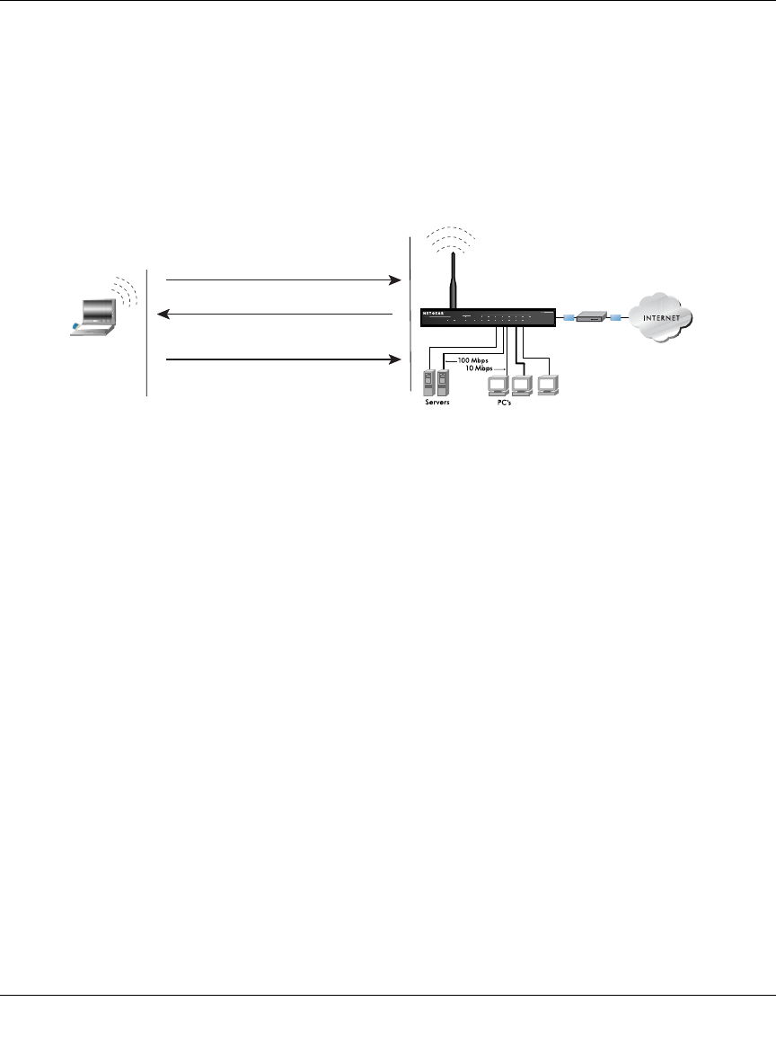
Reference Manual for the 54 Mbps Wireless Travel Router WGR101
Wireless Networking Basics D-5
May 2004 (202-10034-01)
• Shared Key Authentication requires that the station and the access point have the same WEP
Key to authenticate. These two authentication procedures are described below.
WEP Open System Authentication
This process is illustrated in below.
Figure D-1: 802.11 open system authentication
The following steps occur when two devices use Open System Authentication:
1. The station sends an authentication request to the access point.
2. The access point authenticates the station.
3. The station associates with the access point and joins the network.
INTERNET LOCAL
ACT
12345678
LNK
LNK/ACT
100
Cable/DSL ProSafeWirelessVPN Security Firewall
MODEL FVM318
PWR TEST
WLAN
Enable
Access Point (AP)
1) Authentication request sent to AP
2) AP authenticates
3) Client connects to network
Open System
Authentication Steps
Cable or
DLS modem
Client
attempting
to connect
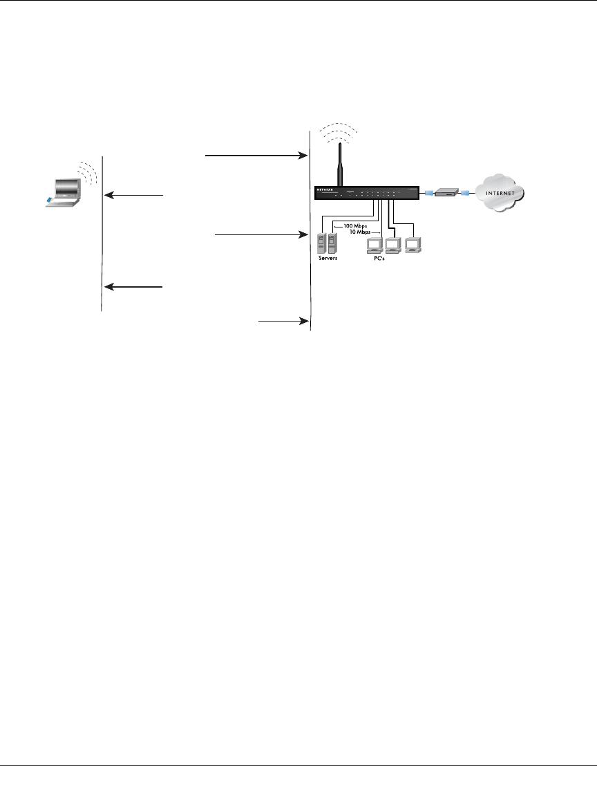
Reference Manual for the 54 Mbps Wireless Travel Router WGR101
D-6 Wireless Networking Basics
May 2004 (202-10034-01)
WEP Shared Key Authentication
This process is illustrated in below.
Figure D-2: 802.11 shared key authentication
The following steps occur when two devices use Shared Key Authentication:
1. The station sends an authentication request to the access point.
2. The access point sends challenge text to the station.
3. The station uses its configured 64-bit or 128-bit default key to encrypt the challenge text, and
sends the encrypted text to the access point.
4. The access point decrypts the encrypted text using its configured WEP Key that corresponds
to the station’s default key. The access point compares the decrypted text with the original
challenge text. If the decrypted text matches the original challenge text, then the access point
and the station share the same WEP Key and the access point authenticates the station.
5. The station connects to the network.
If the decrypted text does not match the original challenge text (i.e., the access point and station do
not share the same WEP Key), then the access point will refuse to authenticate the station and the
station will be unable to communicate with either the 802.11 network or Ethernet network.
INTERNET LOCAL
ACT
12345678
LNK
LNK/ACT
100
Cable/DSL ProSafeWirelessVPN Security Firewall
MODEL FVM318
PWR TEST
WLAN
Enable
Access Point1) Authentication
request sent to AP
2) AP sends challenge text
3) Client encrypts
challenge text and
sends it back to AP
4) AP decrypts, and if correct,
authenticates client
5) Client connects to network
Shared Key
Authentication Steps
Cable or
DLS modem
Client
attempting
to connect

Reference Manual for the 54 Mbps Wireless Travel Router WGR101
Wireless Networking Basics D-7
May 2004 (202-10034-01)
Key Size and Configuration
The IEEE 802.11 standard supports two types of WEP encryption: 40-bit and 128-bit.
The 64-bit WEP data encryption method, allows for a five-character (40-bit) input. Additionally,
24 factory-set bits are added to the forty-bit input to generate a 64-bit encryption key. (The 24
factory-set bits are not user-configurable). This encryption key will be used to encrypt/decrypt all
data transmitted via the wireless interface. Some vendors refer to the 64-bit WEP data encryption
as 40-bit WEP data encryption since the user-configurable portion of the encryption key is 40 bits
wide.
The 128-bit WEP data encryption method consists of 104 user-configurable bits. Similar to the
forty-bit WEP data encryption method, the remaining 24 bits are factory set and not user
configurable. Some vendors allow passphrases to be entered instead of the cryptic hexadecimal
characters to ease encryption key entry.
128-bit encryption is stronger than 40-bit encryption, but 128-bit encryption may not be available
outside of the United States due to U.S. export regulations.
When configured for 40-bit encryption, 802.11 products typically support up to four WEP Keys.
Each 40-bit WEP Key is expressed as 5 sets of two hexadecimal digits (0-9 and A-F). For
example, “12 34 56 78 90” is a 40-bit WEP Key.
When configured for 128-bit encryption, 802.11b products typically support four WEP Keys but
some manufacturers support only one 128-bit key. The 128-bit WEP Key is expressed as 13 sets of
two hexadecimal digits (0-9 and A-F). For example, “12 34 56 78 90 AB CD EF 12 34 56 78 90”
is a 128-bit WEP Key.
Typically, 802.11 access points can store up to four 128-bit WEP Keys but some 802.11 client
adapters can only store one. Therefore, make sure that your 802.11 access and client adapters
configurations match.
Whatever keys you enter for an AP, you must also enter the same keys for the client adapter in the
same order. In other words, WEP key 1 on the AP must match WEP key 1 on the client adapter,
WEP key 2 on the AP must match WEP key 2 on the client adapter, etc.
Note: The AP and the client adapters can have different default WEP Keys as long as the keys are
in the same order. In other words, the AP can use WEP key 2 as its default key to transmit while a
client adapter can use WEP key 3 as its default key to transmit. The two devices will communicate
as long as the AP’s WEP key 2 is the same as the client’s WEP key 2 and the AP’s WEP key 3 is
the same as the client’s WEP key 3.

Reference Manual for the 54 Mbps Wireless Travel Router WGR101
D-8 Wireless Networking Basics
May 2004 (202-10034-01)
How to Use WEP Parameters
Wired Equivalent Privacy (WEP) data encryption is used when the wireless devices are configured
to operate in Shared Key authentication mode. There are two shared key methods implemented in
most commercially available products, 64-bit and 128-bit WEP data encryption.
Before enabling WEP on an 802.11 network, you must first consider what type of encryption you
require and the key size you want to use. Typically, there are three WEP Encryption options
available for 802.11 products:
1. Do Not Use WEP: The 802.11 network does not encrypt data. For authentication purposes, the
network uses Open System Authentication.
2. Use WEP for Encryption: A transmitting 802.11 device encrypts the data portion of every
packet it sends using a configured WEP Key. The receiving 802.11b device decrypts the data using
the same WEP Key. For authentication purposes, the 802.11b network uses Open System
Authentication.
3. Use WEP for Authentication and Encryption: A transmitting 802.11 device encrypts the data
portion of every packet it sends using a configured WEP Key. The receiving 802.11 device
decrypts the data using the same WEP Key. For authentication purposes, the 802.11 network uses
Shared Key Authentication.
Note: Some 802.11 access points also support Use WEP for Authentication Only (Shared Key
Authentication without data encryption). However, the WGR101 does not offer this option.

May 2004 (202-10034-01)
Glossary 1
Glossary
Use the list below to find definitions for technical terms used in this manual.
List of Glossary Terms
10BASE-T
IEEE 802.3 specification for 10 Mbps Ethernet over twisted pair wiring.
100BASE-Tx
IEEE 802.3 specification for 100 Mbps Ethernet over twisted pair wiring.
802.1x
802.1x defines port-based, network access control used to provide authenticated network access and
automated data encryption key management.
The IEEE 802.1x draft standard offers an effective framework for authenticating and controlling user traffic
to a protected network, as well as dynamically varying encryption keys. 802.1x uses a protocol called EAP
(Extensible Authentication Protocol) and supports multiple authentication methods, such as token cards,
Kerberos, one-time passwords, certificates, and public key authentication. For details on EAP specifically,
refer to IETF's RFC 2284.
802.11a
IEEE specification for wireless networking at 54 Mbps operating in unlicensed radio bands over 5GHz.
802.11b
IEEE specification for wireless networking at 11 Mbps using direct-sequence spread-spectrum (DSSS)
technology and operating in the unlicensed radio spectrum at 2.5GHz.
802.11g
A soon to be ratified IEEE specification for wireless networking at 54 Mbps using direct-sequence
spread-spectrum (DSSS) technology and operating in the unlicensed radio spectrum at 2.5GHz. 802.11g is
backwards compatible with 802.11b.
ADSL
Short for asymmetric digital subscriber line, a technology that allows data to be sent over existing copper
telephone lines at data rates of from 1.5 to 9 Mbps when receiving data (known as the downstream rate) and
from 16 to 640 Kbps when sending data (known as the upstream rate).

Reference Manual for the 54 Mbps Wireless Travel Router WGR101
2Glossary
May 2004 (202-10034-01)
ADSL requires a special ADSL modem. ADSL is growing in popularity as more areas around the world
gain access.
AES
Advanced Encryption Standard, a symmetric 128-bit block data encryption technique.
It is an iterated block cipher with a variable block length and a variable key length. The block length and the
key length can be independently specified to 128, 192 or 256 bits.The U.S government adopted the
algorithm as its encryption technique in October 2000, replacing the DES encryption it used. AES works at
multiple network layers simultaneously.
ARP
Address Resolution Protocol, a TCP/IP protocol used to convert an IP address into a physical address (called
a DLC address), such as an Ethernet address.
A host wishing to obtain a physical address broadcasts an ARP request onto the TCP/IP network. The host
on the network that has the IP address in the request then replies with its physical hardware address. There is
also Reverse ARP (RARP) which can be used by a host to discover its IP address. In this case, the host
broadcasts its physical address and a RARP server replies with the host's IP address.
Auto Uplink
Auto UplinkTM technology (also called MDI/MDIX) eliminates the need to worry about crossover vs.
straight-through Ethernet cables. Auto UplinkTM will accommodate either type of cable to make the right
connection.
Cat 5
Category 5 unshielded twisted pair (UTP) cabling. An Ethernet network operating at 10 Mbits/second
(10BASE-T) will often tolerate low quality cables, but at 100 Mbits/second (10BASE-Tx) the cable must be
rated as Category 5, or Cat 5 or Cat V, by the Electronic Industry Association (EIA).
This rating will be printed on the cable jacket. Cat 5 cable contains eight conductors, arranged in four
twisted pairs, and terminated with an RJ45 type connector. In addition, there are restrictions on maximum
cable length for both 10 and 100 Mbits/second networks.
Denial of Service attack
DoS. A hacker attack designed to prevent your computer or network from operating or communicating.
DHCP
An Ethernet protocol specifying how a centralized DHCP server can assign network configuration
information to multiple DHCP clients. The assigned information includes IP addresses, DNS addresses, and
gateway (router) addresses.
DMZ
A Demilitarized Zone is used by a company that wants to host its own Internet services without sacrificing
unauthorized access to its private network.

Reference Manual for the 54 Mbps Wireless Travel Router WGR101
Glossary 3
May 2004 (202-10034-01)
The DMZ sits between the Internet and an internal network's line of defense, usually some combination of
firewalls and bastion hosts. Typically, the DMZ contains devices accessible to Internet traffic, such as web
(HTTP) servers, FTP servers, SMTP (e-mail) servers and DNS servers.
DNS
Short for Domain Name System (or Service), an Internet service that translates domain names into IP
addresses.
Because domain names are alphabetic, they're easier to remember. The Internet however, is really based on
IP addresses. Every time you use a domain name, therefore, a DNS service must translate the name into the
corresponding IP address. For example, the domain name www.example.com might translate to
198.105.232.4. The DNS system is, in fact, its own network. If one DNS server doesn't know how to
translate a particular domain name, it asks another one, and so on, until the correct IP address is returned.
Domain Name
A descriptive name for an address or group of addresses on the Internet. Domain names are of the form of a
registered entity name plus one of a number of predefined top level suffixes such as .com, .edu, .uk, etc. For
example, in the address mail.NETGEAR.com, mail is a server name and NETGEAR.com is the domain.
DoS
A hacker attack designed to prevent your computer or network from operating or communicating.
DSL
Short for digital subscriber line, but is commonly used in reference to the asymmetric version of this
technology (ADSL) that allows data to be sent over existing copper telephone lines at data rates of from 1.5
to 9 Mbps when receiving data (known as the downstream rate) and from 16 to 640 Kbps when sending data
(known as the upstream rate).
ADSL requires a special ADSL modem. ADSL is growing in popularity as more areas around the world
gain access.
DSLAM
DSL Access Multiplexor. The piece of equipment at the telephone company central office that provides the
ADSL signal.
Dynamic Host Configuration Protocol
DHCP. An Ethernet protocol specifying how a centralized DHCP server can assign network configuration
information to multiple DHCP clients. The assigned information includes IP addresses, DNS addresses, and
gateway (router) addresses.
EAP
Extensible Authentication Protocol is a general protocol for authentication that supports multiple
authentication methods.
EAP, an extension to PPP, supports such authentication methods as token cards, Kerberos, one-time
passwords, certificates, public key authentication and smart cards. In wireless communications using EAP, a
user requests connection to a WLAN through an AP, which then requests the identity of the user and

Reference Manual for the 54 Mbps Wireless Travel Router WGR101
4Glossary
May 2004 (202-10034-01)
transmits that identity to an authentication server such as RADIUS. The server asks the AP for proof of
identity, which the AP gets from the user and then sends back to the server to complete the authentication.
EAP is defined by RFC 2284.
ESP
Encapsulating Security Payload.
ESSID
The Extended Service Set Identification (ESSID) is a thirty-two character (maximum) alphanumeric key
identifying the wireless local area network.
Gateway
A local device, usually a router, that connects hosts on a local network to other networks.
IETF
Internet Engineering Task Force. Working groups of the IETF propose standard protocols and procedures for
the Internet, which are published as RFCs (Request for Comment) at www.ietf.org.
An open international community of network designers, operators, vendors, and researchers concerned with
the evolution of the Internet architecture and the smooth operation of the Internet.
IP
Internet Protocol is the main internetworking protocol used in the Internet. Used in conjunction with the
Transfer Control Protocol (TCP) to form TCP/IP.
IP Address
A four-byte number uniquely defining each host on the Internet, usually written in dotted-decimal notation
with periods separating the bytes (for example, 134.177.244.57).
Ranges of addresses are assigned by Internic, an organization formed for this purpose.
IPX
Short for Internetwork Packet Exchange, a networking protocol used by the Novell NetWare operating
systems.
Like UDP/IP, IPX is a datagram protocol used for connectionless communications. Higher-level protocols,
such as SPX and NCP, are used for additional error recovery services.
ISP
Internet service provider.
Internet Protocol
The main internetworking protocol used in the Internet. Used in conjunction with the Transfer Control
Protocol (TCP) to form TCP/IP.
LAN
A communications network serving users within a limited area, such as one floor of a building.

Reference Manual for the 54 Mbps Wireless Travel Router WGR101
Glossary 5
May 2004 (202-10034-01)
LDAP
A set of protocols for accessing information directories.
Lightweight Directory Access Protocol
LDAP. A set of protocols for accessing information directories.
LDAP is based on the standards contained within the X.500 standard, but is significantly simpler. And
unlike X.500, LDAP supports TCP/IP, which is necessary for any type of Internet access. Because it's a
simpler version of X.500, LDAP is sometimes called X.500-lite.
local area network
LAN. A communications network serving users within a limited area, such as one floor of a building.
A LAN typically connects multiple personal computers and shared network devices such as storage and
printers. Although many technologies exist to implement a LAN, Ethernet is the most common for
connecting personal computers.
MAC address
The Media Access Control address is a unique 48-bit hardware address assigned to every network interface
card. Usually written in the form 01:23:45:67:89:ab.
Mbps
Megabits per second.
MDI/MDIX
In cable wiring, the concept of transmit and receive are from the perspective of the computer, which is wired
as a Media Dependant Interface (MDI). In MDI wiring, a computer transmits on pins 1 and 2. At the hub,
switch, router, or access point, the perspective is reversed, and the hub receives on pins 1 and 2. This wiring
is referred to as Media Dependant Interface - Crossover (MDI-X). See also AES.
Maximum Receive Unit
The size in bytes of the largest packet that can be sent or received.
Maximum Transmit Unit
The size in bytes of the largest packet that can be sent or received.
Most Significant Bit or Most Significant Byte
MSB. The portion of a number, address, or field that is farthest left when written as a single number in
conventional hexadecimal ordinary notation. The part of the number having the most value.
MRU
The size in bytes of the largest packet that can be sent or received.
MSB
MSB. The portion of a number, address, or field that is farthest left when written as a single number in
conventional hexadecimal ordinary notation. The part of the number having the most value.

Reference Manual for the 54 Mbps Wireless Travel Router WGR101
6Glossary
May 2004 (202-10034-01)
MTU
The size in bytes of the largest packet that can be sent or received.
NAT
A technique by which several hosts share a single IP address for access to the Internet.
NetBIOS
The Network Basic Input Output System is an application programming interface (API) for sharing services
and information on local-area networks (LANs).
Provides for communication between stations of a network where each station is given a name. These names
are alphanumeric names, up to 16 characters in length.
Network Address Translation
NAT. A technique by which several hosts share a single IP address for access to the Internet.
NIC
Network Interface Card. An adapter in a computer which provides connectivity to a network.
NID
Network Interface Device. The point of demarcation, where the telephone line comes into the house.
packet
A block of information sent over a network. A packet typically contains a source and destination network
address, some protocol and length information, a block of data, and a checksum.
Perfect Forward Secrecy
Perfect Forward Secrecy (PFS) provides additional security by means of a Diffie-Hellman shared secret
value. With PFS, if one key is compromised, previous and subsequent keys are secure because they are not
derived from previous keys.
PKIX
PKIX. The most widely used standard for defining digital certificates.
Point-to-Point Protocol
PPP. A protocol allowing a computer using TCP/IP to connect directly to the Internet.
PPP
A protocol allowing a computer using TCP/IP to connect directly to the Internet.
PPPoA
PPPoA. PPP over ATM is a protocol for connecting remote hosts to the Internet over an always-on
connection by simulating a dial-up connection.

Reference Manual for the 54 Mbps Wireless Travel Router WGR101
Glossary 7
May 2004 (202-10034-01)
PPPoE
PPPoE. PPP over Ethernet is a protocol for connecting remote hosts to the Internet over an always-on
connection by simulating a dial-up connection.
PPP over ATM
PPPoA. PPP over ATM is a protocol for connecting remote hosts to the Internet over an always-on
connection by simulating a dial-up connection.
PPP over Ethernet
PPPoE. PPP over Ethernet is a protocol for connecting remote hosts to the Internet over an always-on
connection by simulating a dial-up connection.
PPTP
Point-to-Point Tunneling Protocol. A method for establishing a virtual private network (VPN) by embedding
Microsoft’s network protocol into Internet packets.
PSTN
Public Switched Telephone Network.
RADIUS
Short for Remote Authentication Dial-In User Service, RADIUS is an authentication system.
Using RADIUS, you must enter your user name and password before gaining access to a network. This
information is passed to a RADIUS server, which checks that the information is correct, and then authorizes
access. Though not an official standard, the RADIUS specification is maintained by a working group of the
IETF.
RFC
Request For Comment. Refers to documents published by the Internet Engineering Task Force (IETF)
proposing standard protocols and procedures for the Internet. RFCs can be found at www.ietf.org.
RIP
A protocol in which routers periodically exchange information with one another so that they can determine
minimum distance paths between sources and destinations.
router
A device that forwards data between networks. An IP router forwards data based on IP source and
destination addresses.
Routing Information Protocol
RIP. A protocol in which routers periodically exchange information with one another so that they can
determine minimum distance paths between sources and destinations.

Reference Manual for the 54 Mbps Wireless Travel Router WGR101
8Glossary
May 2004 (202-10034-01)
router
A device that forwards data between networks. An IP router forwards data based on IP source and
destination addresses.
SSID
A Service Set Identification is a thirty-two character (maximum) alphanumeric key identifying a wireless
local area network. For the wireless devices in a network to communicate with each other, all devices must
be configured with the same SSID.
This is typically the configuration parameter for a wireless PC card. It corresponds to the ESSID in the
wireless Access Point and to the wireless network name. See also Wireless Network Name and ESSID.
Subnet Mask
A mask used to determine what subnet an IP address belongs to. Subnetting enables a network administrator
to further divide an IP address into two or more subnets.
An IP address has two components, the network address and the host address. For example, consider the IP
address 150.215.017.009. Assuming this is part of a Class B network, the first two numbers (150.215)
represent the Class B network address, and the second two numbers (017.009) identify a particular host on
this network.
Subnetting enables the network administrator to further divide the host part of the address into two or more
subnets. In this case, a part of the host address is reserved to identify the particular subnet. This is easier to
see if we show the IP address in binary format. The full address is: 10010110.11010111.00010001.00001001
The Class B network part is: 10010110.11010111
and the host address is 00010001.00001001
If this network is divided into 14 subnets, however, then the first 4 bits of the host address (0001) are
reserved for identifying the subnet.
The subnet mask is the network address plus the bits reserved for identifying the subnetwork. (By
convention, the bits for the network address are all set to 1, though it would also work if the bits were set
exactly as in the network address.) In this case, therefore, the subnet mask would be
11111111.11111111.11110000.00000000. It's called a mask because it can be used to identify the subnet to
which an IP address belongs by performing a bitwise AND operation on the mask and the IP address. The
result is the subnetwork address: Subnet Mask 255.255.240.000 11111111.11111111.11110000.00000000
IP Address 150.215.017.009 10010110.11010111.00010001.00001001
Subnet Address 150.215.016.000 10010110.11010111.00010000.00000000
The subnet address, therefore, is 150.215.016.000.
TCP/IP
The main internetworking protocols used in the Internet. The Internet Protocol (IP) used in conjunction with
the Transfer Control Protocol (TCP) form TCP/IP.
TLS
Short for Transport Layer Security, TLS is a protocol that guarantees privacy and data integrity between
client/server applications communicating over the Internet.

Reference Manual for the 54 Mbps Wireless Travel Router WGR101
Glossary 9
May 2004 (202-10034-01)
The TLS protocol is made up of two layers. The TLS Record Protocol ensures that a connection is private by
using symmetric data encryption and ensures that the connection is reliable. The second TLS layer is the
TLS Handshake Protocol, which allows authentication between the server and client and the negotiation of
an encryption algorithm and cryptographic keys before data is transmitted or received. Based on Netscape’s
SSL 3.0, TLS supercedes and is an extension of SSL. TLS and SSL are not interoperable.
Universal Plug and Play
UPnP. A networking architecture that provides compatibility among networking technology. UPnP
compliant routers provide broadband users at home and small businesses with a seamless way to participate
in online games, videoconferencing and other peer-to-peer services.
UTP
Unshielded twisted pair is the cable used by 10BASE-T and 100BASE-Tx Ethernet networks.
WAN
A long distance link used to extend or connect remotely located local area networks. The Internet is a large
WAN.
WEB Proxy Server
A web proxy server is a specialized HTTP server that allows clients access to the Internet from behind a
firewall.
The proxy server listens for requests from clients within the firewall and forwards these requests to remote
Internet servers outside the firewall. The proxy server reads responses from the external servers and then
sends them to internal client clients.
WEP
Wired Equivalent Privacy is a data encryption protocol for 802.11b wireless networks.
All wireless nodes and access points on the network are configured with a 64-bit or 128-bit Shared Key for
data encryption.
wide area network
WAN. A long distance link used to extend or connect remotely located local area networks. The Internet is a
large WAN.
Wi-Fi
A trade name for the 802.11b wireless networking standard, given by the Wireless Ethernet Compatibility
Alliance (WECA, see http://www.wi-fi.net), an industry standards group promoting interoperability among
802.11b devices.
Windows Internet Naming Service
WINS. Windows Internet Naming Service is a server process for resolving Windows-based computer names
to IP addresses.

Reference Manual for the 54 Mbps Wireless Travel Router WGR101
10 Glossary
May 2004 (202-10034-01)
If a remote network contains a WINS server, your Windows PCs can gather information from that WINS
server about its local hosts. This allows your PCs to browse that remote network using the Windows
Network Neighborhood feature.
WINS
WINS. Windows Internet Naming Service is a server process for resolving Windows-based computer names
to IP addresses.
Wireless Network Name (SSID)
Wireless Network Name (SSID) is the name assigned to a wireless network. This is the same as the SSID or
ESSID configuration parameter.
WPA
Wi-Fi Protected Access (WPA) is a specification of standards-based, interoperable security enhancements
that increase the level of data protection and access control for existing and future wireless LAN systems.

Index 1
Numerics
802.11b D-1
A
Account Name 5-2, 6-4
Address Resolution Protocol B-8
ad-hoc mode D-2
Auto MDI/MDI-X B-15, G-2
Auto Uplink 2-3, B-15, G-2
B
backup configuration 5-7
Basic Wireless Connectivity 4-7
BSSID D-2
C
Cabling B-11
Cat5 cable B-12, G-2
configuration
automatic by DHCP 2-3
backup 5-7
erasing 5-8
restore 5-6
conventions
typography 1-1
crossover cable 2-3, 7-2, B-14, B-15, G-2
customer support 1-ii
D
Default DMZ Server 6-4
denial of service attack B-11
DHCP B-10
DHCP Client ID C-16
DMZ 6-5
DMZ Server 6-4
DNS Proxy 2-3
DNS server C-20
documentation updates 5-6
domain C-20
Domain Name 6-4
domain name server (DNS) B-9
DoS attack B-11
E
EnterNet C-18
erase configuration 5-8
ESSID 4-7, D-2
Ethernet 2-2
Ethernet cable B-11
F
factory settings, restoring 5-8
Flash memory, for firmware upgrade 2-1
front panel 2-6, 2-7
fully qualified domain name (FQDN) 4-4
G
gateway address C-20
H
host name 6-4
Index

2Index
I
IANA
contacting B-2
IETF B-1
Web site address B-7
infrastructure mode D-2
installation 2-3
Internet account
address information C-18
establishing C-18
IP addresses C-19, C-20
and NAT B-7
and the Internet B-2
assigning B-2, B-9
auto-generated 7-3
private B-7
translating B-9
IP configuration by DHCP B-10
IP networking
for Macintosh C-16
for Windows C-2, C-7
L
LAN IP Setup Menu 6-6
LEDs
troubleshooting 7-2
Logout 3-7, 6-3
M
MAC address 7-5, B-8
spoofing 6-4
Macintosh C-19
configuring for IP networking C-16
DHCP Client ID C-16
Obtaining ISP Configuration Information C-20
masquerading C-18
MDI/MDI-X B-15, G-2
MDI/MDI-X wiring B-14, G-5
N
NAT C-18
NAT. See Network Address Translation
netmask
translation table B-6
Network Address Translation 2-3, B-7, C-18
O
Open System authentication D-4
P
package contents 2-4
Passphrase 4-5, 4-10
passphrase 2-2
password
restoring 7-5
PC, using to configure C-21
ping 6-5
placement 4-1
port forwarding behind NAT B-8
PPP over Ethernet C-18
PPPoE C-18
Primary DNS Server 6-4
protocols
Address Resolution B-8
DHCP B-10
Routing Information 2-3, B-2
support 2-1
publications, related B-1
R
range 4-1
restore configuration 5-6
restore factory settings 5-8
Restrict Wireless Access by MAC Address 4-10
RFC
1466 B-7, B-9
1597 B-7, B-9
1631 B-7, B-9

Index 3
finding B-7
RIP (Router Information Protocol) 6-7
router concepts B-1
Router Status 5-1
Routing Information Protocol 2-3, B-2
S
Scope of Document 1-1
Secondary DNS Server 6-4
security 2-2
Shared Key authentication D-4
SSID 4-4, 4-7, 4-8, D-2
stateful packet inspection B-11
static IP address 6-3
Status Light 2-6
subnet addressing B-4
subnet mask B-5, C-19, C-20
T
TCP/IP
configuring C-1
network, troubleshooting 7-4
TCP/IP properties
verifying for Macintosh C-17
verifying for Windows C-6, C-15
troubleshooting 7-1
U
Uplink switch B-14
USB C-18
W
WAN Setup 6-4
WEP D-8
Wi-Fi D-1, D-4
Windows, configuring for IP routing C-2, C-7
winipcfg utility C-6
WinPOET C-18
Wired Equivalent Privacy. See WEP
Wireless Ethernet D-1
Wireless Performance 4-1
Wireless Range Guidelines 4-1
Wireless Security 4-2
World Wide Web 1-ii