Netgear orporated WGR614V2 802.11b/g Wireless Router User Manual FullManual
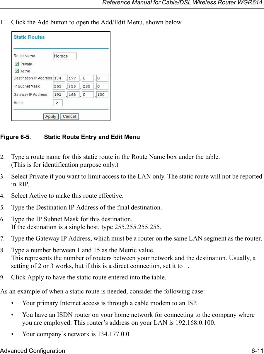
Netgear Incorporated 802.11b/g Wireless Router FullManual
UserManual.wiki
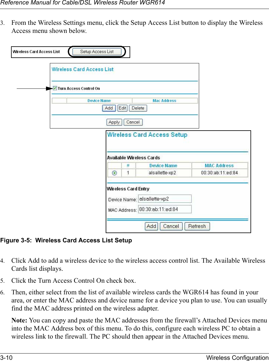
>
Netgear orporated
>
WGR614V2 User Manual
User manual
Navigation menu
Upload a User Manual
Namespaces
Wiki Guide
HTML
PDF
Info
Views
User Manual
Discussion / Help
Navigation


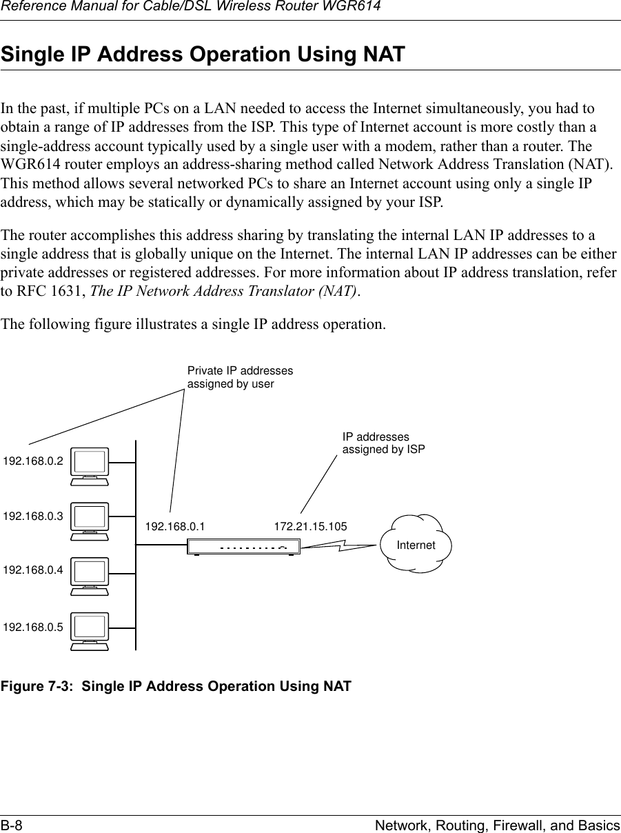
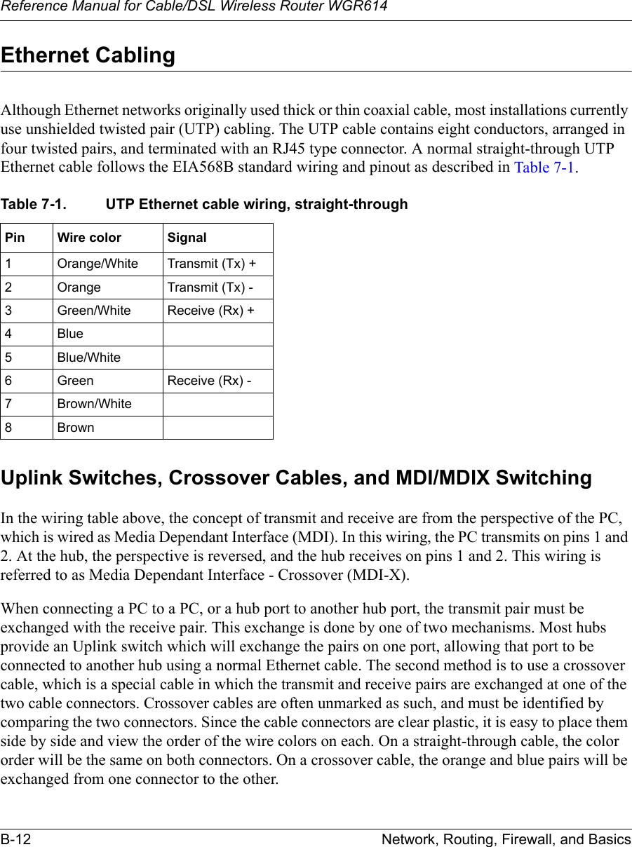
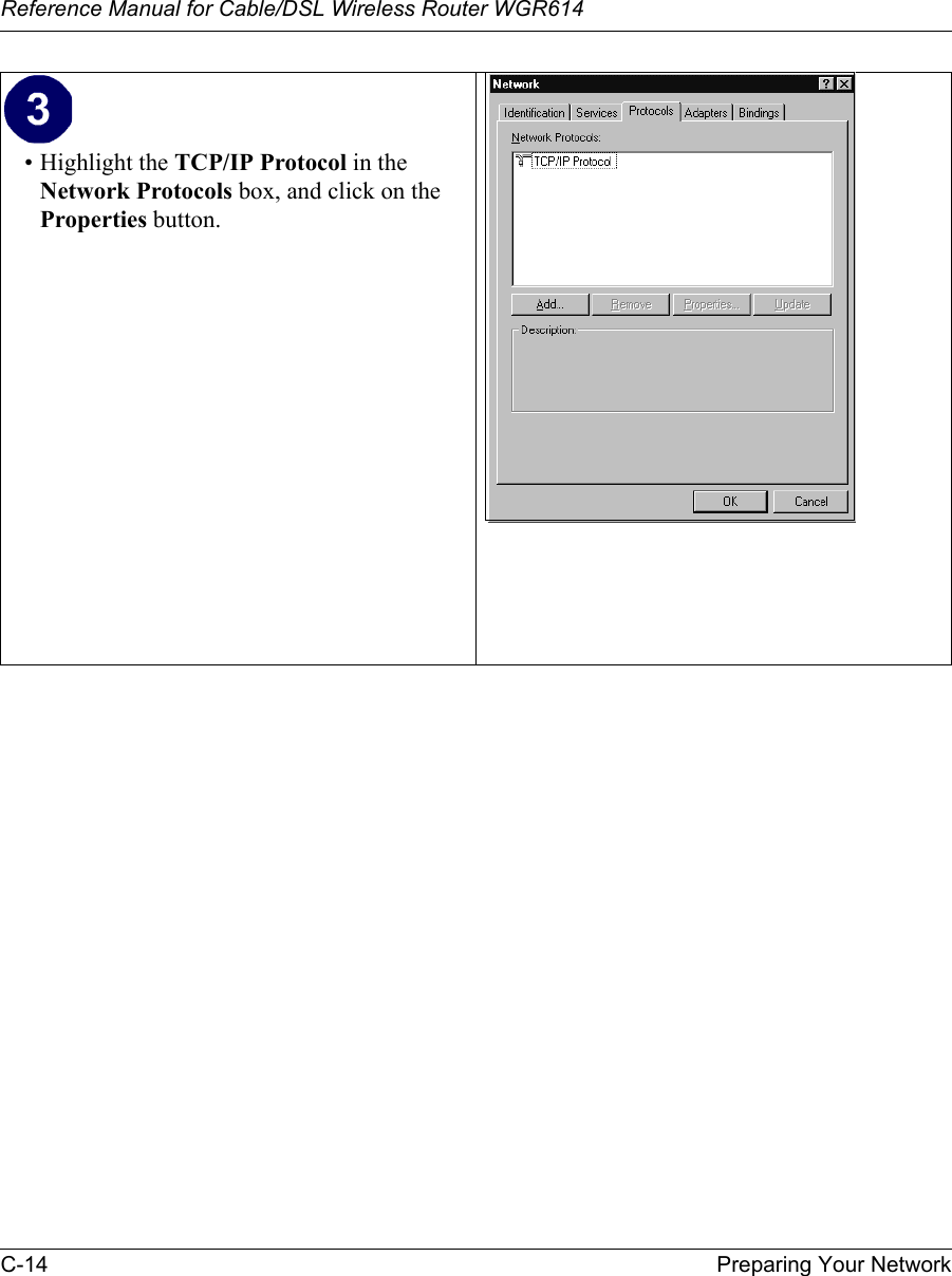
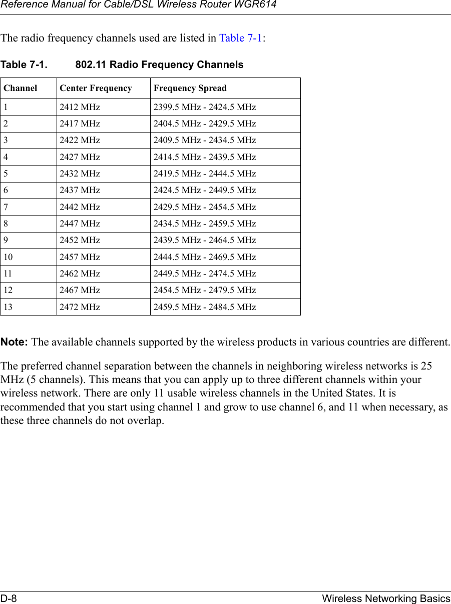
![About This Manual xi Preface About This ManualCongratulations on your purchase of the NETGEAR® Model WGR614 Cable/DSL Wireless Router. The WGR614 router provides connection for multiple personal computers (PCs) to the Internet through an external broadband access device (such as a cable modem or DSL modem) that is normally intended for use by a single PC.AudienceThis reference manual assumes that the reader has basic to intermediate computer and Internet skills. However, basic computer network, Internet, firewall, and VPN technologies tutorial information is provided in the Appendices and on the Netgear website.Typographical ConventionsThis guide uses the following typographical conventions:Conventionsitalics Emphasis.bold times roman User input.courier font Screen text, user-typed command-line entries.[Enter] Named keys in text are shown enclosed in square brackets. The notation [Enter] is used for the Enter key and the Return key.[Ctrl]+C Two or more keys that must be pressed simultaneously are shown in text linked with a plus (+) sign.SMALL CAPS DOS file and directory names.](https://usermanual.wiki/Netgear-orporated/WGR614V2/User-Guide-336908-Page-11.png)